1
Electricity Meters
Residential BS / MID
British Standard
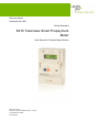
E470 Tokenless Smart Prepayment
Meter
User Manual & Technical Specification
Date: 18.01.2010
Filename: 5236 User Manual Version 1.8.docx
Q Pulse Number: IB090
© Landis+Gyr
Page 2 of 69
Issue: 1.8
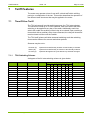
Revision History
Revision History
Issue
1.0
1.1
1.2
1.3
1.4
Date
21.05.07
19.06.07
26.06.07
20.07.07
03.08.07
1.5
1.6
04.09.07
24.10.07
Comments
Initial release for Approval bodies
Amendments to meet approvals specification
2nd round of amendments to meet approvals specification
Further addition to the data sheet to cover LVD requirements
Further additions at section 1.4 and to the data sheet to satisfy TUV
requirements
Supply cabling specification added to section 1.7
Signal strength comments added at section 6.2
1.7
1.8
19.11.08
14.09.09
Revised manual to new branding guidelines and layout
Addition of features to support 5236J-Y functionality
Copyright notice
The material in this document is the property of Landis+Gyr. Our products are under continual
improvement and we reserve the right to make changes without prior notice.
Landis+Gyr
1 Lysander Drive,
Northfields Industrial Estate,
Market Deeping,
Peterborough
PE6 8FB
www.landisgyr.com
© Landis+Gyr
E470 Tokenless Smart Prepayment Meter
Table of Contents
Issue: 1.8
Page 3 of 69
Table of Contents
1
Introduction____________________________________________________________ 6
1.1
Scope ___________________________________________________________________ 6
1.2
Purpose _________________________________________________________________ 6
1.3
Target Group _____________________________________________________________ 6
1.4
Intended Use and Installation ________________________________________________ 6
2
Safety Information ______________________________________________________ 7
2.1
Responsibilities ___________________________________________________________ 7
2.2
Safety Regulations _________________________________________________________ 8
3
Functional Overview ____________________________________________________ 9
3.1
Meter Description _________________________________________________________ 9
3.2
Metrological Functions ______________________________________________________ 9
3.3
Temperature ____________________________________________________________ 10
3.4
Real Time Clock __________________________________________________________ 10
3.5
Faceplate Details _________________________________________________________ 11
3.6
Customer Display_________________________________________________________ 11
4
Meter Operation _______________________________________________________ 12
4.1
Energy Registers _________________________________________________________ 12
4.2
Push Button Operation ____________________________________________________ 12
4.3
Buzzer Operation _________________________________________________________ 13
4.4
Tamper Detection ________________________________________________________ 14
4.5
Normal SIM Card Removal _________________________________________________ 15
5
Installation and Binding of External Devices________________________________ 20
5.1
Binding Process __________________________________________________________ 20
5.2
Decommissioning_________________________________________________________ 24
6
Commands and meter data ______________________________________________ 26
E470 Tokenless Smart Prepayment Meter
© Landis+Gyr
Page 4 of 69
Issue: 1.8
Table of Contents
6.1
Ad hoc (Immediate) Reads ________________________________________________ 26
6.2
Change of Tenancy/Supplier _______________________________________________ 26
6.3
Supply Restoration _______________________________________________________ 28
6.4
Profiling _______________________________________________________________ 28
6.5
Scheduled Reads ________________________________________________________ 29
7
Tariff Features _________________________________________________________31
7.1
Time-Of-Use Tariff _______________________________________________________ 31
7.2
Block Tariff _____________________________________________________________ 32
7.3
Price-Per-Unit Tariff Plan __________________________________________________ 34
7.4
Examples of Tariff types __________________________________________________ 35
7.5
Standing Charge_________________________________________________________ 35
7.6
Effective Date/ Future Tariff _______________________________________________ 36
8
Prepayment and Accounting Functions ____________________________________40
8.1
Credit Mode ____________________________________________________________ 40
8.2
Present Balance Register __________________________________________________ 40
8.3
Payments Log ___________________________________________________________ 40
8.4
Total Credit Register _____________________________________________________ 41
Cost Registers ____________________________________________________________________ 41
8.5
Friendly Non-disconnect___________________________________________________ 41
8.6
Customer Cards _________________________________________________________ 42
8.7
Emergency Credit ________________________________________________________ 42
8.8
Standing Charge Register/Collection _________________________________________ 43
8.9
Debt Repayment ________________________________________________________ 44
8.10
Currency Conversion _____________________________________________________ 45
9
Meter Displays _________________________________________________________46
9.1
General ________________________________________________________________ 46
9.2
Icons __________________________________________________________________ 47
© Landis+Gyr
E470 Tokenless Smart Prepayment Meter
Table of Contents
Issue: 1.8
Page 5 of 69
9.3
Present Balance Register ___________________________________________________ 47
9.4
Present Balance, Emergency Credit Available ___________________________________ 48
9.5
Present Balance, Emergency Credit in Use _____________________________________ 49
9.6
Active Rate Display _______________________________________________________ 49
9.7
Payment Received ________________________________________________________ 49
9.8
Display Cycle Options _____________________________________________________ 50
9.9
Purchase Code Entry ______________________________________________________ 56
9.10
Installation ______________________________________________________________ 57
10
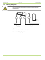
Wiring Diagram ________________________________________________________ 60
11
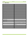
Data Sheet ____________________________________________________________ 61
12
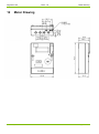
Meter Drawing _________________________________________________________ 62
13
Maintenance and Service________________________________________________ 63
13.1
Meter Check _____________________________________________________________ 63
13.2
Meter Testing____________________________________________________________ 63
13.3
Post Installation Configuration Changes _______________________________________ 63
14
Measures in the Event of Faults __________________________________________ 64
14.1
Operating Faults _________________________________________________________ 64
14.2
Disconnecting the Meter ___________________________________________________ 64
14.3
Repairing the Meter _______________________________________________________ 64
15
Decommissioning and Disposal __________________________________________ 66
16
Glossary of Terms and Standards ________________________________________ 67
16.1
Acronyms _______________________________________________________________ 67
16.2
Measurement Units _______________________________________________________ 67
17
Declaration of Conformity _______________________________________________ 68
18
Glossary of Terms _____________________________________________________ 69
E470 Tokenless Smart Prepayment Meter
© Landis+Gyr
Page 6 of 69
Issue: 1.8
1
Introduction
1.1
Scope
Introduction
This user manual applies to the British Standard 5236J-Y SMS messaging
Tokenless prepayment meter.
1.2
Purpose
This manual contains all information required for the application of the
meters for the intended purpose. This includes:
1.3
Characteristics, construction and functionality of the meters.
Information about possible dangers, their consequences and
measures on how to prevent them.
A detailed description of the tasks to be performed during the
entire life-cycle of the meters (configuration, installation,
commissioning, operation, maintenance, and disposal).
Target Group
The contents of this user manual are intended for technically qualified personnel of energy supply companies responsible for system planning,
installation and commissioning, operation, maintenance, decommissioning
and disposal of the meters.
1.4
Intended Use and Installation
The 5236 meters record active energy consumption in single phase two
wire networks. For this purpose they are directly installed in the supply line
by the energy supply company and are read regularly for energy charging
purposes. They are used according to the technical specifications stated in
the respective data sheets and below.
The meter is intended for installation in a residential environment by
qualified personnel. The meter conforms to British Standard in its
mechanical specification and is suited to installation in any situation that
also meets this standard. The meter must be installed away from powerful
sources of electromagnetic interference.
There are no user serviceable parts within the meter and the meter must be
returned to the manufacturer or an authorized partner for repair and/or
maintenance. There are no permissible adjustments to meter installation
procedure or meter operation outside those covered by the detailed
operational instructions contained within this document.
If the equipment is used in a manner not specified by the manufacturer the
protection provided by the equipment may be impaired.
© Landis+Gyr
E470 Tokenless Smart Prepayment Meter
Safety Information
2
Issue: 1.8
Page 7 of 69
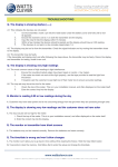
Safety Information
Attention is drawn as follows in the individual chapters of this user manual
with classified word symbols and pictographs to the relevant danger level,
i.e. the severity and probability of any danger:
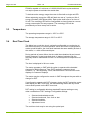
Definition of Danger
This symbol is used to indicate a possibly dangerous situation which could
result in severe physical injury or a fatality.
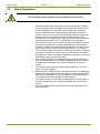
Definition of Warning
This symbol is used to indicate a possibly dangerous situation which could
result in minor physical injury or material damage.
Definition of Note
This symbol is used to indicate general details and other useful information.
In addition to the danger level, all safety information also describes the type
and source of the danger, its possible consequences and measures to
counteract the danger.
2.1
Responsibilities
The owner of the meters – normally the utility – is responsible that all
persons engaged on work with meters:
Have read and understood the relevant sections of the user
manual.
Are sufficiently qualified for the work to be performed.
Strictly observe the safety regulations and the operating
information in the individual chapters.
In particular, the owner of the meters bears responsibility for the protection
of persons, prevention of material damage and the training of personnel
(Landis+Gyr. provides training courses for this purpose on specific
equipment; please contact the relevant agent if interested).
E470 Tokenless Smart Prepayment Meter
© Landis+Gyr
Page 8 of 69
2.2
Issue: 1.8
Safety Information
Safety Regulations
The following safety regulations must be observed at all times:
© Landis+Gyr
This equipment does not contain a disconnection device. Means
for disconnection from the supply must be provided as part of the
building installation. Do not work on the equipment unless the
supply is disconnected. If disconnection is done by removal of
fuses or other cut-outs, the removed disconnection devices must
be kept secure from replacement while work is performed. If
disconnection is provided by a switch, the switch shall conform to
the requirements of IEC 947-1 and IEC 947-3 or equivalent.
This equipment does not contain an overcurrent protection device.
Overcurrent protection must be provided as part of the building
installation. Maximum overcurrent device rating is 100 Amp at 415
Volts, conforming to the requirements of BS1361, or equivalent.
The maximum rating of the meter is 100A and requires connecting
conductors of 25mm2. Failure to do so could result in irreparable
damage to the meter. If smaller connecting conductors are used an
appropriate mains fuse must be used.
Only suitably trained and qualified personnel shall be allowed to
work on the equipment. Local safety standards shall be observed
and shall take precedence over these regulations in points of
conflict.
The meters must be held securely during installation. They can
cause injuries if dropped.
Meters that have fallen must not be installed, even if no damage is
apparent, but must be returned for testing to the service and repair
department responsible (or the manufacturer). Internal damage
can result in functional disorders or short-circuits.
The meters must on no account be cleaned with running water or
with high-pressure devices. Water penetrating can cause shortcircuits.
The meter terminal cover should be secured in place before any
load is supplied.
E470 Tokenless Smart Prepayment Meter
Functional Overview
Issue: 1.8
3
Functional Overview
3.1
Meter Description
Page 9 of 69
The meter requires a single phase, two wire mains supply with a reference
voltage of 230V, 50Hz. The meter is rated at 10, 15, or 20 – (100) Amps
registering kWh to class B (MID). The meter’s internal measurement
coefficient is 1 and therefore does not affect the supply’s phase angle.
The meter is fitted with a 100A contactor for the disconnection of supply
operating automatically when prepay credit has expired or by manual
command in the event of a change of tenancy, for instance.
The meter is fitted with a single pole, normally open, voltage free relay
rated at 230V 2A at unity and 0.5pf. This relay is internally controlled by
time-of-use switches and may be used to control an ancillary circuit.
The meter is fitted with a GSM modem and will use SMS messaging to
receive credit transactions, tariff and configuration updates. It may provide
periodic scheduled reads and additionally ad hoc reads of register values
and other data on command.
The meter features energy registers for four rates and one total export
energy register. The meter may be configured to maintain time-of-use
tariffs, block tariffs or complex combinations of the two.
The meter is fitted with a standard IEC1107 optical port for factory and on
site programming as necessary.
Additional features include but are not limited to:
3.2
Half Hour Profiling – configurable on/off as required
Prepayment accounting in £ and €
Cost per hour & usage calculations + display
Tamper reporting
Display of data with a liquid crystal display (LCD).
Metrological Functions
The current measurement is based on shunt technology.
The microprocessor receives the measured analog signals (U and I)
through an A/D-converter. It determines the energy direction and calculates
the energy which is subsequently processed in accordance with the meter
constant and fed to the relevant rate register determined by rate control.
The microprocessor also controls the data communication with the display
and serial interface and ensures a safe operation in the event of a voltage
failure.
The entire meter’s data is recorded in a Ferro-electric Random Access
Memory (FRAM) under the control of the microprocessor. All kWh registers
are stored in the FRAM and are updated every 1/100th of a kWh. The
E470 Tokenless Smart Prepayment Meter
© Landis+Gyr
Page 10 of 69
Issue: 1.8
Functional Overview
FRAM is capable of a minimum of 10,000,000,000 write cycles and does
not require power to maintain the stored data.
To indicate active energy usage the meter is fitted with a single red LED.
When registering energy the LED will flash at a rate of 1 pulse per Wh of
energy recorded (1000 pulses kWh). Each pulse shall have an on time of
20 mS. The metrology LED will be configurable to show forward or reverse
energy consumption for test purposes. The metrology LED will be
permanently on when creep lock is active.
3.3
Temperature
The operating temperature range is –25°C to +55°C.
The storage temperature range is -30°C to +85°C.
3.4
Real Time Clock
The Meter has a real time clock, optionally configurable to synchronise to
the mains frequency in normal operation. When the meter is configured for
mains synchronisation, the clock shall maintain the same stability as that of
the mains, i.e. within ±30 seconds/year.
During periods of power failure the time shall be maintained by an internal
battery powered, crystal controlled clock. In battery backed mode the
accuracy shall be maintained to within 15 minutes/year at a temperature of
20°C.
The time is displayed in 24-hour mode.
The meter operates on GMT with the option to operate with scheduled
changes for British Summer Time (BST) applied to customer timed
functions, i.e. Tariff Switching Times, No-Disconnect Period and the clock
displays in Customer Displays.
The meter may be configured to remain in GMT throughout the year with no
change for DST.
If configured to operate with DST changes, during the BST period the meter
shall display the BST clock time, the rate-switching matrix and any timed
events shall operate on the BST time clock.
DST setting is configurable allowing standard European settings or any
other combination of DST settings. Configurable settings:
Start and end calendar month
Start and end week, first –forth or last
Start and end day
Start and end time
Adjustment hours
The real time clock may be set using the optical port.
© Landis+Gyr
E470 Tokenless Smart Prepayment Meter
Functional Overview
3.5
Issue: 1.8
Page 11 of 69
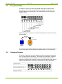
Faceplate Details
In addition to meter type and metrological markings according to MID
requirements, the meter faceplate will show register names below the
triangle indicators on the display. The faceplate will show the following
register names:
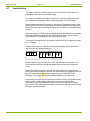
Additionally the functions of the two buttons fitted to the front of the meter
are described:
Purchase
Code
+
Cycle
Display
Press
Press & Hold
Emergency
Credit
The meters serial number and barcode will be laser marked onto the front
of the meter case. Serial numbers are allowed with up to 16 characters.
3.6
Customer Display
The meter is fitted with a custom display providing 4 starburst characters
and 7 seven-segment characters. The display has a backlight. Separate
icon will indicate currency and kWh units. The display will provide an
indication of GSM signal strength. Pointers along the bottom edge will link
with the facia artwork to show which parameters are being displayed.
E470 Tokenless Smart Prepayment Meter
© Landis+Gyr
Page 12 of 69
Issue: 1.8
4
Meter Operation
4.1
Energy Registers
Meter Operation
Display of energy registers is configurable to show 5 or 6 whole numbers.
All energy registers are configurable to show between 0 and a maximum of
2 decimal places (up to 1 decimal place with 6 whole numbers).
All energy registers are displayed with leading zeros.
All energy registers will roll over from 99999.99 to 00000.00 kWh.
(999999.9 to 000000.0 when set to 6 whole numbers.
All energy registers are incremented for every 1 Wh of forward energy
consumed.
The meter will record reverse or export energy into an export energy
register, [configurable option].
The meter has up to 4 time-of-use registers. Each TOU register will
become active according to the TOU switching plan configured into the
meter.
4.2
Push Button Operation
The meter is fitted with two push buttons as described in section 2.5. The
left hand blue button is used for stepping thru the meters’ display cycle.
Each press will advance the configured display sequence by one display.
If the display sequence has been partially cycled and the push button is not
pressed for 30 seconds the display sequence will revert to the default
display.
The right hand orange push button shall be used to evoke the Emergency
Credit feature.
4.2.1
Payment Code Entry
The transfer of payments is made by sending a 20 digit encrypted code to
the meter. Normally this would be transferred by SMS messaging, however
in cases such as the communication system is unable to send the top-up to
the meter, a secondary method for transfer is available.
In normal commissioned operation the meter will allow the customer to
enter the purchase code using the two push buttons on the meter. The
entry process is detailed in the section Meter Displays 6.9.
When expecting a purchase code the meter allows a maximum of {20}
digits to be entered.
If the code entered is successful the meter shows the value of the purchase
on the display.
© Landis+Gyr
E470 Tokenless Smart Prepayment Meter
Meter Operation
Issue: 1.8
Page 13 of 69
The meter will allow codes to be re-entered for up to 10 minutes and will
allow the entry of 5 sets of invalid codes. If a valid code is not entered after
a total of 10 minutes, or 5 invalid attempts are made during this period, the
display will revert back to the Default Operating display. If 5 invalid entries
are made the facility will be locked out until the next hour.
The meter will allow a maximum of 5 sets of Payment code entries in a
24hr period.
Example
1pm:
Enter invalid code 5 times
Must wait until 2pm before allowed to re-enter code
2pm
Enter invalid code 5 times
Must wait until 3pm before allowed to re-enter code
3pm
Enter invalid code 5 times
Must wait until 4pm before allowed to re-enter code
4pm:
Enter invalid code 5 times
Must wait until 5pm before allowed to re-enter code
5pm
Enter invalid code 5 times
Facility locked out until 00:01 next day
If no button presses are detected after 60 seconds the display will revert
back to the normal operating display.
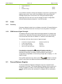
4.2.2
Installation and Binding
A further use of the code entry mode is to instigate the binding process for
external devices or an installation mode.
When instigating these processes a 6 digit pin is entered into the first 6
digits of the payment code. If the entered pin corresponds to one of the
configured pins then the meter will enter the appropriate mode. See
installation section.
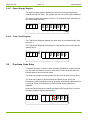
4.3
Buzzer Operation
The meter uses an audible buzzer to indicate to the consumer the following
events:
4.3.1
Low Credit warning
Valid Button press
Incorrect Entry of Purchase Code.
Low Credit Warning
The Low credit warning will operate when the Present Balance register
value falls below the Emergency Credit Availability point and Emergency
credit is available.
If the Present Balance register falls below the Emergency Credit Availability
point during a Non-Disconnection period, the Low credit warning will be
suspended until the Non Disconnection period has ended.
E470 Tokenless Smart Prepayment Meter
© Landis+Gyr
Page 14 of 69
Issue: 1.8
Meter Operation
For low credit warning the buzzer shall sound for 30 seconds followed by 2
second beeps every 30 seconds for total of 5 minutes.
The low credit warning is stopped if the Display Cycle button is pressed.
The Low Credit Warning is a configurable item and may be disabled.
4.3.2
Valid Button Press
The buzzer sounds a short beep each time a valid Display Cycle button
press is made.
The valid button press beep is a configurable item and may be disabled.
4.3.3
Invalid Purchase Code
If an Invalid Purchase Code is entered, the meter will give a 1 second beep
to signify the code is incorrect.
4.4
Tamper Detection
The meter includes several anti tamper features.
4.4.1
Reverse Energy Detection
If the meter is configured to operate in a reverse energy fraud detection
mode the meter will alternate a warning message on the display should a
fraud attempt be made by running current backwards through the meter.
The reverse energy-warning message is triggered when the reverse power
exceeds a programmable threshold level of between 1-10 Amps for a
period of 10Wh. A reverse energy event can optionally be communicated to
the utility information system immediately or returned with scheduled read
meter status.
The meter will store the number of RED tamper events detected together
with the time and date of the last recorded event.
Once triggered the reverse energy-warning message can only be reset by a
command programmed either via the IEC 1107 port or by SMS message.
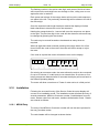
4.4.2
SIM Card Removal Detection
The meter is fitted with two detection devices to protect the SIM card fitted
to the meter. An initial detection device monitors the opening of the flap
covering the SIM aperture. A second detector monitors the movement of
the SIM carriage outwards from the meter. The sim carriage detection
circuit operates when on or off supply. On triggering of either detector, the
meter stores the number of SIM tamper events together with the time and
date of the last event. On the event of a tamper event the meter will enact
all, any one or none [configurable] of the following actions:
© Landis+Gyr
E470 Tokenless Smart Prepayment Meter
Meter Operation
Issue: 1.8
Page 15 of 69
Visually display a tamper detection message; see Meter Display
section.
If the meter is on supply; the opening of the SIM flap may be
reported to the utilities information system by instantly sending an
SMS message.
Optionally the meter may be configured to open the main
contactor.
Resetting of the tamper flag/supply reconnection can be achieved by
system command or using the meter optical port.
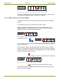
4.5
Normal SIM Card Removal
In normal operation the SIM card may be ‘hot’ swapped by the utility
without disconnecting the supply to the meter and the customer. Upon
opening the main SIM flap the meter may send a tamper message as
described in Tamper detection (if configured); following the sending of the
message the meter will power down the SIM ready for removal. The meter
indicates that the SIM may be removed by flashing the signal strength
symbols on the display. Upon replacement of the SIM and closure of SIM
flap the meter will reenergise the device and the meter will send the new
SIM number to the utilities information system. The message will consist of
Meter serial number, SIM number and MPAN.
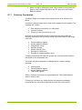
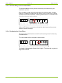
4.6
Operational modes
The E470 meter can be configured to operate in several different
operational modes that can be implemented remotely. The following section
details the operational modes that are supported by the meter.
4.6.1
Credit mode
The meter can be configured to operate in credit mode. In this mode of
operation the meter will not open the contactor (unless instructed) and will
ignore any credit values sent to the meter. When in credit mode the default
operating meter display is the active register display.
4.6.2
Prepayment mode
The meter can be configured to operate in prepayment mode. In this mode
of operation the meter will open the contactor when the credit value in the
meter falls below a zero value. To close the contactor the meter requires a
payment to be made to suffice any negative balance registered on the
meter. When in prepayment mode the default operating meter display is the
remaining credit display.
4.6.3
Single wallet mode
The meter can be configured to operate in a single wallet mode. In this
mode of operation the meter will use the value of credit held in the present
balance register for collection of both gas and electricity usage. The
electricity meter reduces the present balance for gas usage on receipt of
each ½ hour message from the gas meter using the gas cost today data.
E470 Tokenless Smart Prepayment Meter
© Landis+Gyr
Page 16 of 69
Issue: 1.8
Meter Operation
When the present balance register falls to zero, the meter will send a pass
through message to the gas meter to close its valve and disconnect the gas
flow. The electricity meter will also open its own contactor.
Accounting in single wallet mode
The meter receives cost data from the gas meter in the form of a Gas Cost
since Start of Day on each ½ hour and daily in the form of a Day’s Gas
Cost value, received at midnight.
The meter uses the received Gas Cost since Start of Day value to reduce
Present Balance for gas usage every ½ hour.
The Gas Cost since Start of Day value is a rising value of cost since the
start of the day, reset each midnight.
Example:
the meter calculates a particular ½ hours usage in the following manner:
The meter stores a value of the gas cost since start of the day
At midnight the stored value will be reset
When a new value is received the stored value is subtracted from
the new value to gas the last 30 minutes usage. The present
balance register is reduced by the calculated value.
The original stored value is overwritten with the new value.
Cost since start of day
value (rising)
30 min value
£
03:30
03:00
02:30
02:00
01:30
01:00
00:30
00:00
. . .
The meter records the total value collected from the Present balance
register through ½ hourly messages, to enable reconciliation to the Day’s
Gas Cost value. This is recorded daily for a rolling 28 days, and ca
recorded as extra data within the gas daily profile held within the electricity
meter.
As there is the possibility of a ½ hourly message being missed a
reconciliation process will be made against the Day’s Gas Cost value
received each day or as part of the data catch up process. The Day’s Gas
Cost value will be considered as the master value. On receipt of the Day’s
Gas Cost value the meter reconciles the amount for the appropriate day
against the recorded amount collected through the ½ hourly messages.
© Landis+Gyr
E470 Tokenless Smart Prepayment Meter
Meter Operation
Issue: 1.8
Page 17 of 69
Present balance register in single wallet mode
The present balance register within the electricity meter holds the credit or
debt value for both gas and electricity usage. Electricity costs are taken in
the normal way, gas costs are taken as described in 7.4.2. Emergency
credit may be applied in the normal way.
Supply disconnect/reconnect in single wallet mode
After a disconnect and when credit is next added, sufficient to place the
meters back into prepaid credit the following occurs:
4.6.4
The meter will allow the customer to reconnect the electricity
supply using the button on the front of the meter.
The meter will generate a pass-through message for the gas meter
to request instantaneous gas reconnect. The message will be
passed on the next 30 minute boundary.
The meter will cancel any unsent disconnect pass-through
messages on receipt of a payment message, sufficient to place the
meter back in prepaid credit.
PAYG mode
The meter can be configured to operate in pay-as-you-go (PAYG) mode. In
this mode of operation the meter will not disconnect at zero but will allow
the user to accumulate a certain amount of debt. Providing that the user
keeps within an agreed amount of debt supply will remain connected for the
customer.
To support this mode the meter can be configured to hold a PAYG
disconnection value, the value has a range of 0 to -500 (debt).
When operating in PAYG mode, the meter will disconnect supply when the
present value in the meter falls below the configured PAYG disconnection
value.
Emergency credit operation is disabled by configuration when using the
PAYG mode, debt recover will still operate as normal.
4.6.5
Gas Credit mode
The meter can be used to configure the operating mode of a paired gas
meter. Using this mode the mode of the gas meter can be switched
between prepayment and credit operation. A request to change the mode
of operation for the gas meter can take upto ½ an hour as the request is
dependant on a pass through message to perform the request.
E470 Tokenless Smart Prepayment Meter
© Landis+Gyr
Page 18 of 69
4.7
Issue: 1.8
Meter Operation
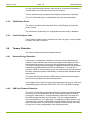
Load limiting
The meter supports a load limiting function which when in operation will
provide the user with only a limited supply.
The meter is enabled to operate in Load Limit mode by configuration and
may operate in conjunction with credit, prepayment or PAYG modes.
When enabled and while the meter is operating in Prepayment mode, load
limiting shall only become active when the present balance falls below zero.
When active the usual switching of supply is overridden by the load limiting
function.
When operating in PAYG mode load limiting shall only become active when
the present balance falls below the PAYG Disconnection value. Supply
disconnection is overridden by the load limiting function.
The meter is configured with a Load limit value that has an operating range
of 0 - 24.00kW
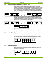
When load limiting is in operation the following display will be alternated
with the normal operating displays:
L I MI
£ t i ng
€
on
Pence/ kWh
When Load limiting is enabled the meter will maintain the contactor in a
closed position while the measured power (kW) is below the Load Limit
value.
When the measured power exceeds the Load Limit value supply will be
disconnected and contactor opened. On disconnection the display will show
the OFF message for [5] seconds, followed by the PUSH BUTTON
message. The supply will then be made available for reconnection.
On pressing the meters push button the contactor will be closed and supply
reconnected. Load is again measured. If part of the load has been
removed and remains under the Load Limit value the supply will remain
connected. If the measured load again exceeds the Load Limit value supply
will again be disconnected.
© Landis+Gyr
E470 Tokenless Smart Prepayment Meter
Meter Operation
Issue: 1.8
Page 19 of 69
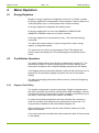
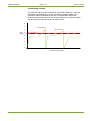
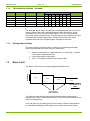
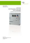
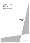
Load limiting example:
The load limit value for the customer is set at 5kW. When the customer
exceeds the threshold value in the first instance power supply is cut.
Customer reduces load and power can be reconnected. When the
customer exceeds the value in the second instance, the customer again
has to reduce household load to reconnect power.
8
7
Value exceeded
6
kWh
5
usage
X
Value exceeded X
Load Limit threshold
4
3
2
1
0
Customer usage pattern
E470 Tokenless Smart Prepayment Meter
© Landis+Gyr
Page 20 of 69
5
Issue: 1.8
Installation and Binding of External Devices
Installation and Binding of External Devices
The installation process is in two parts; joining the metering components
together by a binding process and notification of the metering system to the
head End System. An automated notification process exists within the
meter however this may not be supported by the HES. Where the
automated process is not supported a manual method would be employed.
This section describes the automated process only.
5.1
Binding Process
The binding process is used to join devices to the electricity meter. Once
bound, the devices will ignore transmissions from any other meters within
the vicinity. The units will remain in this state until rebound.
During the process the devices exchange communication addresses and
security keys, logging serial number into the electricity meter. These serial
numbers are in turn displayed on the In-home display to provide
confirmation to the installer.
A remote process is available to prevent meters communicating when not
required (i.e. loss of gas supply contract).
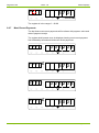
5.1.1
Binding and installation mode code entry
Both binding and automatic installation processes use a 6 digit PIN to
instigate a particular process with the meter. The meter holds a record of 3
PIN’s
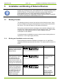
Action
Press and hold both push
buttons on the front of the
electricity meter until the
display shows:
The active number in the
code sequence is shown
as a flashing digit. To
increment the number
press the blue button, the
number will increase from
0 though to 9 then back to
0
To move to the next
number in the sequence,
press the orange button.
The sequence will move
one digit to the left and
the active digit shown
flashing. If an error is
made in entering a
© Landis+Gyr
Display
CODE
£
€
00 00
Button Actions
Hold both buttons.
Pence/ kWh
CODE
£
€
10 00
Pence/ kWh
CODE
£
€
100 00
Pence/ kWh
Press blue button
to increment the
number .
Press orange
button to move to
next digit.
Press and hold
orange button to
step backward to
previous digit
E470 Tokenless Smart Prepayment Meter
Installation and Binding of External Devices
Issue: 1.8
Page 21 of 69
particular number then the
sequence can be moved
back by pressing and
holding the orange button.
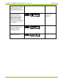
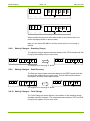
All binding and installation
codes are 6 digits in
length. Once the sixth
digit has been entered
then the code can be
offered to the meter by
pressing and holding both
push buttons.
CODE
If the code matches a
code pre-programmed
code then a pass
message is shown
CODE
If not then and error
message is shown.
CODE
£
€
100 00
Pence/ kWh
£
€
Press both buttons
to offer code
entered.
PASS
Pence/ kWh
£
€
Er r o r
Pence/ kWh
E470 Tokenless Smart Prepayment Meter
© Landis+Gyr
Page 22 of 69
Issue: 1.8
Installation and Binding of External Devices
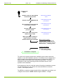
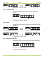
Installer Fits
Meter
Installer enters 6 digit default
commissioning code
Meter enters installation
mode
Installer enters MPAN/Cust #
Code entered using two
push buttons
Any remaining credit entered
from previous meter
Code entered using two
push buttons
Arrears entered from
previous meter
Code entered using two
push buttons
Meter fitter enters personal
authorisation code
Code entered using two
push buttons
Meter generates random 6
digit numbers for meter
removal and meter exchange
Meter sends to system:
MPAN
Meter serial #
Payment card # Credit value set
Arrears value set Register readings
Removal code
Exchange Code
System sends Meter:
Configuration Update
(Previous meter setting s
if an exchange meter)
Installation complete
The meter will recognise and accept a default service code to allow the
installer to enter the installation process. The default service code will be 6
digits in length and programmed during factory configuration. NOTE: it is
expected the service code will be valid across all meters. Following
completion of the commissioning process the Default service code
operation will be disabled.
On acceptance of service code the meter will enter the installation process.
The first parameter for entry will be the customer MPAN or customer
number. See Display section.
The MPAN or customer number length will be configurable up to allow up to
16 digits to be entered. NOTE: Default length of MPAN - 13 digits.
© Landis+Gyr
E470 Tokenless Smart Prepayment Meter
Installation and Binding of External Devices
Issue: 1.8
Page 23 of 69
The MPAN number is entered into the meter using the Purchase Code
entry procedure but will allow only the configured number of digits to be
entered. The meter will store the initial MPAN entered then require the
number to be re-entered and checked against the original entry. If the two
entries match then the MPAN is considered as correct and the process will
move the next step.
Following successful MPAN entry the meter, a configurable option will allow
entry of credit from a previous meter. The Present Balance register will be
shown and the meters current value able to be edited using the two push
buttons. See Display section 6.8.
Following the entry/editing of the Present balance register, a configurable
option will allow an Arrears value to be transferred from a previous meter.
The current Arrears Register will be shown and the value able to be edited
using the two push buttons. See Display section 6.8.
Following the entry of the Arrears register the meter will ask for an
Authorisation code to be entered. This code is an identifier for the meter
installer.
The Authorisation Code will be 6-digits in length. See Display section 6.8.
Once installation data has been entered the meter will randomly generate
two 6-digit codes. These codes will allow a decommission process to occur
when entered at a later date by a meter engineer. The two codes have the
following purposes:
Meter removal Code – Used where the meter type is to be
replaced completely, i.e. with a credit meter
Meter exchange Code – Used to swap (clone) a meter such as in
end of life exchange programme.
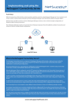
The two codes are sent to the system following the commissioning process.
The operation of codes is explained in Decommissioning 3.11.
The two codes are stored in memory one against each of the processes.
Once commissioning is complete the meter will transmit the commissioning
details to the system. The message will consist of:
Data Item
Date and Time stamp
Electricity Meter Status flags2
Returned in1
H
H
Details
Message ID
MPAN/Customer #
Meter Serial Number
SIM Card Number
Payment Card Number
Credit Mode
Emergency credit flags
Present Balance Register
P
P
P
P
P
P
P
P
Message ID = INSTALL
E470 Tokenless Smart Prepayment Meter
Denotes credit or prepayment operating mode
Denotes emergency credit taken or not
© Landis+Gyr
Page 24 of 69
Issue: 1.8
Data Item
Arrears Register
Rate 1 kWh register
Rate 2 kWh register
Rate 3 kWh register
Rate 4 kWh register
Total kWh register
Export energy register
Meter Removal Code
Meter Exchange code
Meter Fitter Authorisation Code
Returned in1
P
P
P
P
P
P
P
P
P
P
Installation and Binding of External Devices
Details
Return Data – Following the installation process the meter will be sent a full
configuration set of operation data including tariffs etc, from the utilities
information system. Additionally the meter may be sent Present balance
data and Arrears data if the meter is a replacement meter subject to an
exchange process.
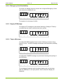
5.2
Decommissioning
Decommissioning of a meter is achieved by entering one of the two
decommissioning codes sent to the system at installation. NOTE: The
meter engineer would be instructed of the codes by use of the system.
The entry of the Decommissioning Codes is achieved using the using the
standard Purchase Code entry procedure - see display section. Once 6
digits have been entered the installer can offer the code to the meter by
pressing and holding both buttons for 2 seconds. If the code does not
match the either the removal code or exchange code held in memory, the
meter will show ‘Error’ and clear the entry. Lock out procedure will apply
according to the Purchase Code entry scheme.
5.2.1
Meter Exchange
When the meter exchange code is entered the meter will send a snapshot
of meter data to the system. The information will include:
Data Item
Date and Time stamp
Electricity Meter Status flags2
Returned in1
H
H
Details
Message ID
MPAN/Customer #
Meter Serial Number
Credit Mode
Emergency credit flags
Present Balance Register
Arrears Register
Rate 1 kWh register
Rate 2 kWh register
Rate 3 kWh register
P
P
P
P
P
P
P
P
P
P
Message ID = EXCHANGE
© Landis+Gyr
Denotes credit or prepayment operating mode
Denotes emergency credit taken or not
E470 Tokenless Smart Prepayment Meter
Installation and Binding of External Devices
Data Item
Rate 4 kWh register
Total kWh register
Export energy register
Issue: 1.8
Returned in1
P
P
P
Page 25 of 69
Details
NOTE: The transfer of all metering data to the system will allow all
parameters to be sent back down to an exchange meter when the same
MPAN is used in the new meter.
5.2.2
Meter Removal
When the meter removal code is entered, the meter will send a snapshot of
metering data to allow a final read to be arranged. The information will
include:
Data Item
Date and Time stamp
Electricity Meter Status flags2
Returned in1
H
H
Details
Message ID
MPAN/Customer #
Meter Serial Number
Credit Mode
Emergency credit flags
Present Balance Register
Arrears Register
Rate 1 kWh register
Rate 2 kWh register
Rate 3 kWh register
Rate 4 kWh register
Total kWh register
Export energy register
P
P
P
P
P
P
P
P
P
P
P
P
P
Message ID = REMOVAL
E470 Tokenless Smart Prepayment Meter
Denotes credit or prepayment operating mode
Denotes emergency credit taken or not
© Landis+Gyr
Page 26 of 69
Issue: 1.8
6
Commands and meter data
6.1
Ad hoc (Immediate) Reads
Commands and meter data
The meter will respond to requests for Ad hoc register reads. The meter will
respond immediately with the requested data. The ad hoc read request
may consist of any metering parameter held within meters memory.
As an example a standard request may consist of:
MPAN/Cust #
Electricity Meter Serial Number
Rate 1 kWh register
Rate 2 kWh register
Rate 3 kWh register
Rate 4 kWh register
Total kWh register
Export energy register.
Automatically the meter will return the following data in the return message
header:
Electricity Meter Status
Date and Time stamp
The above data would fit within a single SMS message.
6.2
Change of Tenancy/Supplier
The meter is capable of handling changes in tenancy or supplier by zeroing
or revaluing various registers within the meter upon receipt of a change of
tenancy/supplier command (CoT/S) by the system.
A CoT/S command can be configured to operate either immediately or at
some time in the future; the CoT/S command will contain an activation date
and time for when the process should occur. The meter will only perform
the operation at the configured date and time unless requested
immediately.
The CoT/S command is able to change or zero the following registers/
features:
© Landis+Gyr
Reset or overwrite Credit/Debt register, configurable from 0 to
maximum top-up value.
Where the meter is in emergency credit the EC and any DCLR
value will be cleared.
Reset or overwrite Total Debt register, configurable from 0 to
maximum value.
E470 Tokenless Smart Prepayment Meter
Commands and meter data
Issue: 1.8
Page 27 of 69
Clear credit transaction log.
Option to open/close meters contactor. (shows OFF display
second CoT/S command to close contactor).
Option to Zero PPU tariff plan.
Option to reset Billing Period.
Zero Standing Charges.
Zero total credit.
Zero total payments.
Option to clear any future tariffs.
Clear Profile data log.
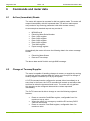
The CoT/S command will trigger a Snapshot of readings. The returned data
includes data required for prepayment or credit operation and consists of:
Data Item
Date and Time stamp
Electricity Meter Status flags
Returned in1
H
H
Details
Message ID
MPAN/Customer #
Meter Serial Number
Credit Mode
Emergency credit flags
Present Balance Register
Arrears Register
Rate 1 kWh register
Rate 2 kWh register
P
P
P
P
P
P
P
P
P
Message ID = COTS
See2 below
Denotes credit or prepayment operating mode
Denotes emergency credit taken or not
1 Returned In’ column denotes whether the item is returned in the message
header (H) or as part of the message payload.
2 Meter status information includes flags to indicate fault conditions/status
of the electricity meter.
Flags will indicate the following:
Watchdog Error
Real Time Clock Error
FRAM (memory) error
Program download active
Meter in Emergency mode
E470 Tokenless Smart Prepayment Meter
Reverse energy detected
SIM card flap tamper
SIM carriage detected
Fingerprint stats error
Fingerprint other error
© Landis+Gyr
Page 28 of 69
Issue: 1.8
Rate 3 kWh register
Rate 4 kWh register
Total kWh register
Export energy register
Commands and meter data
P
P
P
P
Following a CoT/S the meter will be reprogrammed with new tariff plans,
TOU switching as required.
6.3
Supply Restoration
When operating in credit mode a reconnection command may be issued to
enable the electricity supply to be reinstated by the customer.
The command will consist of:
Close electricity meter contactor
Time and date for event or immediate
Acknowledgement request.
At the designated time, and if requested, the electricity meter will allow the
customer to close the contactor. The meter will scroll the message ‘Press
Orange button for power’ as described in section 6.7. When the consumer
presses the Emergency credit button the contactor will close and supply
restored.
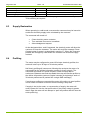
6.4
Profiling
The meter may be configured to record 30-minute electricity profiles; the
meter will store up to 30 days of 30-minute profiles.
Half hourly profiling will commence following the receipt at the meter of a
command from the utilities information system for them to begin. The
command will consist of a profile request, a start and stop date or
continuous. Between start and stop dates the meter will transfer profiles to
the utilities information system at regular intervals [A single days’ worth of
30-minute profiles can be packed into a single SMS message].
If continuous profiles are requested the meter will continue to send profiles
until a further command is received communicating a stop date.
If supply is lost to the meter, on reconnection of supply, the meter will
record ‘power fail’ into the lost profile slots. If the power outage is greater
than 3 days the meter will not attempt to ‘pad’ lost profiles and will clear the
entire profile log.
© Landis+Gyr
E470 Tokenless Smart Prepayment Meter
Commands and meter data
6.5
Issue: 1.8
Page 29 of 69
Scheduled Reads
The meter will be able to ‘Push’ register readings back to the utilities
information system at regular predefined intervals. The reading interval will
be configurable by the system.
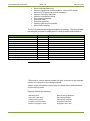
The data returned to the system will hold both credit and prepayment
information for the meter. A scheduled read will be a single SMS message
in length. The returned message format will be as follows:
Data Item
Date and Time stamp
Electricity Meter Status flags2
Returned in1
H
H
Details
Message ID
MPAN/Customer #
Meter Serial Number
Credit Mode
Emergency credit flags
Present Balance Register
Arrears Register
Rate 1 kWh register
Rate 2 kWh register
Rate 3 kWh register
Rate 4 kWh register
Total kWh register
Export energy register
P
P
P
P
P
P
P
P
P
P
P
P
P
Message ID = SCHED_READ
Denotes credit or prepayment operating mode
Denotes emergency credit taken or not
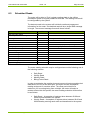
The meter-reading schedule may be configured around the following one of
the following routines:
Daily Read
Weekly Read
Monthly Read
Billing Period Read.
In order to randomise the reading time and prevent all meters sending their
data back to the CS at the same time, the meter will take a snapshot
reading at the end of a random offset. The offset period shall be a
maximum of 2 hours beginning from midnight; the meter will select a
random offset within this period, the meter-reading schedule will therefore
be as follows:
E470 Tokenless Smart Prepayment Meter
Daily Read – A snapshot of registers taken between 00:00 and
02:00 and transferred to the system.
Weekly Read – A snapshot of registers taken between 00:00 and
02:00 Monday morning each week and transferred to the system.
© Landis+Gyr
Page 30 of 69
Issue: 1.8
Commands and meter data
Monthly Read – A snapshot of registers taken between 00:00 and
02:00 on the first day of each calendar month and transferred to
the system.
Billing Period Read - A snapshot of registers is taken between
00:00 and 02:00 at the end of a billing period, as defined in the
billing period section, and transferred to the system.
The meter may be configured not to send scheduled reads.
The meter will additionally store the last sent scheduled read as a
contingency in case of communication failures.
© Landis+Gyr
E470 Tokenless Smart Prepayment Meter
Tariff Features
7
Issue: 1.8
Page 31 of 69
Tariff Features
The meter may operate a time-of-use tariff, a block tariff within a billing
period or a combination of the two. This section describes the operation of
the different tariff structures that may be applied to the meter.
7.1
Time-Of-Use Tariff
The TOU scheme will provide switching across four TOU rate registers.
The scheme will hold up to 15 time switches; each time switch will allow
switching to be applied to any day of the week. Additionally each time
switch will enable the auxiliary control relay to be closed. Upon reaching a
time switch with an auxiliary relay close command, the relay will close and
remain closed until the next time switch.
The TOU tariff scheme will allow seasonal switching such that switching
times can be different for summer and winter periods.
Seasons may be set to:
Summer (S)
Winter (W)
All Year (A)
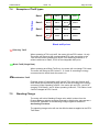
7.1.1
Operate from last Sunday in March to last Sunday in October.
Operate from last Sunday in October to last Sunday in March.
Operates throughout the year without any seasonal changes
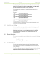
TOU Switching Scheme
A diagram of the full rate-switching scheme is given below.
Switch #
Season
Start Time
Rate
1
2
3
4
5
6
7
8
9
10
11
12
13
14
15
S/W/A
HH:MM
1 to 4
E470 Tokenless Smart Prepayment Meter
Applicable Days of operation
M
T
W
T
F
S
Auxiliary relay
S
Open/Closed
© Landis+Gyr
Page 32 of 69
7.1.2
Issue: 1.8
Tariff Features
TOU Switching Scheme – Example
Switch #
Season
Start Time
Rate
1
2
3
4
5
S
S
S
W
W
00:00
07:00
00:00
00:00
07:00
1
2
3
1
2
Applicable Days of operation
M
T
W
T
F
S
Y
Y
Y
Y
Y
Y
Y
Y
Y
Y
Y
Y
Y
Y
Y
Y
Y
Y
Y
Y
Y
Y
Y
Auxiliary relay
S
Y
Y
Y
Closed
Open
Closed
Closed
Open
The example above shows a seasonal weekday/weekend tariff. During the
summer season the meter switches between rates one and two during
weekdays in a seven hour on/off peak pattern. The aux relay is closed
during the nightly off peak period. At weekends the meter switches to rate 3
and closes the off peak relay all day. During winter months the meter
operates the seven-hour off peak pattern throughout the week.
7.1.3
Holidays/Special Days
The meter may be configured with 15 dates to be used as special days.
During a special day the meter may be configured to:
7.2
Switch to and remain in a particular rate (1 to 4) all day, or remain
in the normal switching scheme.
Close the Auxiliary relay all day.
Act in a ‘Friendly Non-Disconnect’ mode all day.
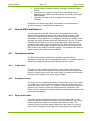
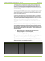
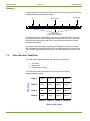
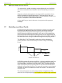
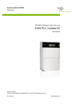
Block Tariff
Price/Unit
The Block Tariff structure is shown diagrammatically below:
Block 1
Block 2
Block 3
Block4
Consumption in
kWh
Power Switch
Threshold Values
The meter will hold three Power switch threshold values; these values
represent the value in kWh between blocks. The block tariff will begin at the
start of a billing period.
From the start of a new billing period, the number of kWh’s consumed will
be recorded as a Billing Period Usage Value. When the recorded value
© Landis+Gyr
E470 Tokenless Smart Prepayment Meter
Tariff Features
Issue: 1.8
Page 33 of 69
reaches a threshold value, the PPU tariff will be changed according to the
price defined for the next block. Block four has no limit. When reaching
block four the meter will continue to charge at the block four rate until a new
billing period is reached. If a threshold value is not entered then the
previous block will remain operative.
The Billing Period Usage value shall be calculated from any individual rate
register (1 to 4) or the total register.
When operating a Combination tariff the meter will take a snapshot of all
kWh registers upon reaching a Threshold Value. This will allow auditing of
the credit value applied to the meter i.e. how many units were charged at
which price.
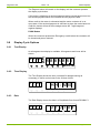
7.2.1
Billing Periods
The Billing Period is the period in days or calendar months over which the
Block Tariff is applied. In order to allow quarterly billing the Billing Period
has a configurable start date and duration. The Billing Period duration may
be configured as a number of days or calendar months. Billing periods rollon unless reset for COT or COS.
The Billing Period shall have duration defined in the range:
1 to 115 days; or
1-12 calendar months. [Start date between 1st and 28th day].
The Billing Period has a start date defined as DDMM. The Billing Period
end date is calculated as the start date plus the number of days or calendar
months of the Billing Period. Where a monthly period is applied the meter
will use the day specified in the start date as the start day of the next period
following the specified number of month’s duration. The Billing Period shall
end at 24:00 on the Billing Period end date and the next Billing Period shall
start automatically.
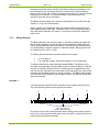
Example 1
If a billing period is specified as 3 calendar month duration starting on the
5th June the billing period would operate as follows:
J
5th
5th
5th
J
A
S
Billing Period ( 3 months)
O
N
D
Billing Period (3 months)
Block Tariff
kWh usage value reset
Next B.P. automatically starts
On the 5th of each 3rd month the Block tariff’s billing period usage value is
reset. As a result the block tariff resets and uses block 1 prices until the first
power switch threshold is reached.
E470 Tokenless Smart Prepayment Meter
© Landis+Gyr
Page 34 of 69
Issue: 1.8
Tariff Features
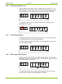
Example 2
If a billing period is specified as 90-day duration starting on the 5th June the
billing period would operate as follows:
5th
1st(calculated)
2nd (calculated)
J
J
A
S
Billing Period ( 90 days)
O
N
D
Billing Period (90 days)
Block Tariff
kWh usage value reset
Next B.P. automatically starts
The billing period is calculated 90 days form the start date. After each 90
day period the Block tariff’s billing period usage value is reset. As a result
the block tariff resets and uses block 1 prices until the first power switch
threshold is reached.
The meter holds information regarding the billing cycle held in the meter,
this information uncludes the start of the next billing period, the start of the
current billing period and what day of the current billing period the meter is
in.
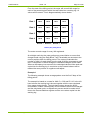
7.3
Price-Per-Unit Tariff Plan
The tariff prices applied by the meter can be complied from:
TOU tariff
Block tariff
Combination of both
TOU Prices
The tariff will consist of a matrix of up to 16 prices as shown
diagrammatically below:
Rate 1
PPU 1
PPU 5
PPU 9
PPU 13
Rate 2
PPU 2
PPU 6
PPU 10
PPU 14
Rate 3
PPU 3
PPU7
PPU 11
PPU 15
Rate 4
PPU 4
PPU8
PPU 12
PPU 16
Block 1 Block 2 Block 3 Block 4
Block tariff prices
© Landis+Gyr
E470 Tokenless Smart Prepayment Meter
Tariff Features
Page 35 of 69
Examples of Tariff types
TOU Prices
7.4
Issue: 1.8
Rate 1
PPU 1
PPU 5
PPU 9
PPU 13
Rate 2
PPU 2
PPU 6
PPU 10
PPU 14
Rate 3
PPU 3
PPU7
PPU 11
PPU 15
Rate 4
PPU 4
PPU8
PPU 12
PPU 16
Block 1 Block 2 Block 3 Block 4
Block tariff prices
TOU Only Tariff
When operating a TOU only tariff, the meter will use PPU values 1-4 only.
The meter will charge at the corresponding PPU value according to the
TOU rate the meter is switched to by the TOU switching scheme i.e. if
scheme switches to Rate2, PPU2 is the chargeable kWh price.
Block Tariff (Single Rate)
When operating as a Block Tariff only, the meter will not change TOU rates.
The meter will charge at PPU values 1, 5, 9 and 13 according to energy
consumed and to which block the meter is in.
Combination Tariff
Example shows a Combination tariff using 2 TOU rates and 3 block tariff
rates. Meter will dynamically change the PPU rate according to the energy
consumed. When operating in Block 1 the meter will use PPU 1 and 2 for
charging TOU Rates 1 and 2. When operating in Block 2, TOU Rates 1 and
2 will be charged at PPU 5 and 6.
7.5
Standing Charge
The meter will hold a Standing Charge value which is taken form the
Present Balance register at regular intervals by dividing the value across a
time period. Operation of the Standing Charge register is detailed in
Accounting Functions.
The standing charge value will use the effective date as applied to the PPU
Tariff Data.
E470 Tokenless Smart Prepayment Meter
© Landis+Gyr
Page 36 of 69
7.6
Issue: 1.8
Tariff Features
Effective Date/ Future Tariff
The meter will be capable of holding a second [deferred] set of tariff data
with a future activation date. Activation date will include day, month, and
year.
When the activation date applied to the future tariff is reached the future
tariff will overwrite the present active tariff. The meter will use the new
values from 00:00 on the activation date. A second Standing Charge Value
may be a component of this deferred tariff data.
A future tariff may me sent to the meter in conjunction with a payment
message.
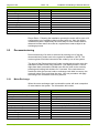
7.7
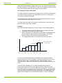
Daily Resolved Block Tariffs
A Daily Resolved Block Tariff is block tariff that is applied on a daily basis.
By resolving the block tariff daily the user does not receive a particular
charge for kWh consumption at the beginning of the month (normally
higher) followed by different pricing later, prices are in effect spread daily
and costs smoothed throughout the billing period. As the usage during the
billing period will vary, the meter will perform a daily reconciliation to ensure
the correct amount of charge is made according to the set pricing blocks.
Price/kWh
The Daily Block Tariff Threshold for each block will be calculated by
dividing the Block Tariff Threshold by the number of days in the Billing
Period.
Block 1
Block 2
Block 3
Block4
Daily Consumption
kWh
Daily Block Tariff Thresholds
At 00:00 the meter will reset and use Block 1 pricing to calculate costs from
the kWh usage. The meter will continue to calculate with Block 1 pricing
until consumption reaches the first Daily Block Tariff Threshold. When the
days consumption becomes greater than the first block tariff threshold the
meter will move to Block 2 pricing. The meter will continue to move forward
in blocks until block 4 is reached; the meter will remain in this block until a
midnight reset.
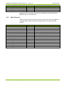
The meter will operate in a similar manner when moving between ToU
rates and the configured pricing. [tbd: Register from which usage is defined]
© Landis+Gyr
E470 Tokenless Smart Prepayment Meter
Tariff Features
Issue: 1.8
Page 37 of 69
Rate 1
kWh A
kWh B
kWh C
kWh D
Rate 2
kWh E
kWh F
kWh G
kWh H
Rate 3
kWh I
kWh J
kWh K
kWh L
Rate 4
kWh M
kWh N
kWh O
kWh P
Time-of-Use prices
From the start of the billing period, the meter will record kWh usage for
each of the potential prices within the tariff table into a working log. 16
values will be stored. This is diagrammatically shown below:
Block 1 Block 2 Block 3 Block 4
Block (tier) tariff prices
The meter records usage for every Wh registered.
At midnight each day the meter performs a reconciliation to ensure that
charges made using the Daily Block Tariff Thresholds are accurate to the
current position within the billing period. The meter will calculate the
number of kWh’s for each block from the total of kWh’s consumed at each
rate. A comparison of actual charges to calculated charges will be made.
Where a discrepancy has occurred, the calculated values will be used and
copied into the working log. A correction to the Present balance will be
made either as a positive or negative credit adjust.
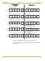
Example 1
The following example shows a usage pattern over the first 5 days of the
billing period.
The example is based on a costs for kWh C = 0.20 and D 0.10. In the left
hand column the working log is shown together with the cost calculated
from usage during the day. The right hand column shows the 00:00
reconciliation. Where a discrepancy occurs between the amounts charged
and the calculated costs, an adjustment process would be made at this
time to the Present Balance register and the new values copied into the
working log.
E470 Tokenless Smart Prepayment Meter
© Landis+Gyr
Page 38 of 69
Issue: 1.8
Tariff Features
Daily Calculated Costs and
Working Log
Midnight Reconciliation
Day 1
Consumption during day 4 kWh
Rate 1
For a 4 kWh total:
kWh A
kWh B
kWh C
kWh D
0
0
2
2
Daily
Threshold
0
0
Amount
charged from
start BP
2
Day 2
Consumption during day 3 kWh = 7 kWh total
kWh A
Rate 1
kWh B
0
Daily
Threshold
kWh C
0
0
0
kWh C
kWh D
0
2
2
0
0
2
0.50
Calculated
Amount
OK for day 1
For a 7 kWh total:
kWh A
kWh B
kWh C
kWh D
0
0
4
3
0.90
3
2
kWh B
0
Cumulative
Threshold
kWh D
4
kWh A
0.50
Amount
charged
Cumulative
Threshold
0
0
4
0.90
Calculated
Amount
OK for day 2
Day 3
Consumption during day 1 kWh = 8 kWh total
kWh A
Rate 1
kWh B
0
Daily
Threshold
kWh C
0
0
kWh D
5
0
For a 8 kWh total:
3
2
Amount
charged
Day 4
Consumption during day 0 kWh = 8 kWh total
kWh A
Rate 1
kWh B
0
Daily
Threshold
kWh C
0
0
0
2
2
Consumption during day 5 kWh = 13 kWh total
kWh A
Rate 1
Daily
Threshold
kWh B
0
kWh C
0
0
0
3
2
kWh D
0
0
6
2
0
6
kWh B
kWh C
kWh D
0
0
8
0
0
0
8
kWh A
kWh B
kWh C
kWh D
0
0
10
3
0
0
1.60
Calculated
Amount
Too many units given at price D,
corrected values copied to working
log, usage recalculated
Cumulative
Threshold
1.40
Calculated
Amount
kWh A
Cumulative
Threshold
2.30
Amount
charged
0
Too many units given at price D,
corrected values copied to working
log, usage recalculated
kWh D
10
kWh C
1.40
Amount
charged
Day 5
kWh B
Cumulative
Threshold
kWh D
6
kWh A
1.10
10
2.30
Calculated
Amount
OK for day 5
At the end of the billing period the meter resets the working log.
The meter is configurable to calculate either in a daily resolved or standard
block tariff mode.
© Landis+Gyr
E470 Tokenless Smart Prepayment Meter
Tariff Features
7.8
Issue: 1.8
Page 39 of 69
Climate Change levy
To enable the meter to be used against commercial tariffs it must be able to
cope with the UK Climate Change Levy (CCL). At present the levy is
applied to customers using over 3000 kWh’s per quarter year (~33kWh per
day). In addition to the levy higher rate VAT is applied to usage above this
value.
The meter will hold a CCL charge value between 0.000 and 99.999
pence/kWh (present CCL charge 0.456 pence/kWh).
The meter will also hold two VAT values, VAT rate 1 and Vat rate 2. VAT
rate 1 will be used to define the level of VAT already applied to the normal
tariff prices within the tariff table. VAT rate 2 will hold the higher rate value.
The meter is capable of applying CCL and VAT rate 2 to usage above a
configurable daily de-minimis value. The meter will hold values for both
CCL and VAT 2 application. This will ensure future proofing in case future
CCL and VAT application thresholds no longer coincided.
The meter records the monetary amount of charges taken from the Present
Balance register from the start of the billing period. This is used for
reconciliation purposes at the end of the billing period.
At 00:00, following a day’s usage, the meter will calculate an average daily
usage value using the total registered kWh’s from the start of the billing
period and the number of days lapsed.
If the calculated average daily amount is greater than the de-minimis value
for CCL then the following day, the CCL charge will be applied to each kWh
consumed.
If the calculated average daily amount is greater the de-minimis value for
VAT rate 2 then the difference between VAT rate 1 and VAT rate 2 will be
applied to each kWh consumed.
At the end of the billing period the monetary amount taken over the period
will be stored together with a time stamp and the working value reset.
At the end of the billing period the meter will be reconciled against a billing
read raised in the suppliers system. The system will require meter readings
and monetary charges raised during the billing period and stored within the
meter. Where a discrepancy occurs between billing and meter values a
credit adjust value will be applied.
E470 Tokenless Smart Prepayment Meter
© Landis+Gyr
Page 40 of 69
Issue: 1.8
Prepayment and Accounting Functions
8
Prepayment and Accounting Functions
8.1
Credit Mode
The meter may be configured to operate in a credit mode. When operating
in credit mode the meter will not open its contactor (unless instructed) and
ignore any credit values set into the meter. The default operating display
will be the active Rate Register display.
8.2
Present Balance Register
The Present Balance register is a continuously updated record of credit
available for payment of energy consumption, standing charge collection
and debt recovery. The Present Balance register will be reduced every time
a kWh of energy is consumed. The meter will deduct one PPU value at the
active rate each time the Active Rate register records a whole kWh of
usage. Standing Charge and Debt Recovery will also periodically reduce
the Present Balance register. The Present Balance register will record in
both positive and negative values with negative values shown as Debt.
When receiving a Credit Top-up transaction, the Present Balance register
will be incremented by the monetary value of transaction.
The Present Balance register values shall be in Pounds (€ following a
currency conversion) and hold a maximum value of £999.99.
If the Present Balance register is exhausted, the supply shall be
disconnected until the Present Balance register is brought back into credit,
provided the meter is not in a Non-Disconnect period or Emergency Credit
is evoked.
It shall be possible to alter the Present Balance register by a Credit Adjust
command.
8.3
Payments Log
The Meter shall maintain a log of the last 20 payments received.
The log shall consist of:
© Landis+Gyr
Date of payment received
Value of payment received
Flag to denote whether the payment was received by SMS or by
customer button entry.
E470 Tokenless Smart Prepayment Meter
Prepayment and Accounting Functions
8.4
Issue: 1.8
Page 41 of 69
Total Credit Register
Total Credit Register that shall record the total value of purchased credit
accepted by the Meter since it was commissioned. The value of each Credit
Top-up will be added to the Total Credit register plus any credit
adjustments made by a Credit Adjust Command.
The Total Credit Register shall be displayed in Pounds or Euros to 2 d.p
(whole pence or cents) without leading zeros’, and in the range £0.00 to
£99999 with rollover to zero at £99999.99.
The Total Credit Register shall be reset to zero following:
8.5
A Change of Tenancy (see Data Transfers)
A Change of Currency (see Currency Conversions).
Cost Registers
The meter provides budgeting information to the customer in the form of
cost per hour and cost today.
Cost per Hour is calculated on all charges normally applied within the last
hour and is displayed from £0.01 to £99.99. The register is calculated on a
three second average.
Cost Today stores the actual £ cost for the current day and includes all
normal charges. The register will be updated whenever the main Present
Balance register is adjusted.
Range from £0.01 to £99.99.
8.5.1
Total Number of Payments Register
The Meter shall maintain a Total Number of Payments Register that shall
record the total number of times a valid Credit Top-up transaction was
received by the meter since it was commissioned.
Each time a valid Credit Top-up is received the register will be incremented
by one and will range 0 to 65535 with rollover to zero at 65535.
The Total Number of Payments Register shall be reset to zero following:
8.6
A Change of Tenancy (see Data Transfers)
A Change of Currency (see Currency Conversions).
Friendly Non-disconnect
The meter offers a facility to prevent disconnection of the contactor at
certain times of the day even when prepaid credit falls below zero. Each
day type (Mon to Sun) may be programmed with a start and end time for
E470 Tokenless Smart Prepayment Meter
© Landis+Gyr
Page 42 of 69
Issue: 1.8
Prepayment and Accounting Functions
the friendly period. Friendly periods may differ on each day type. If prepaid
credit reaches zero during a friendly period the contactor will remain closed
until the end of that period.
If prepaid credit reaches zero during a friendly period the meter will
continue to charge for energy consumed at the appropriate PPU rate.
Charges will be shown as a debt value in the present balance display.
The ‘friendly’ periods can be set either by the factory or configured by
optical port or configuration SMS message.
8.7
Customer Cards
The prepayment mechanism for this meter is Tokenless. However for sake
of convenience each utility customer will receive a magnetic card for means
of account identification. The utilities information system will use the
magnetic card to identify the meter and customer, i.e. when the customer
purchases credit at a POS.
The card will contain a 19-digit number, which is programmed into the
meter during factory configuration, and transferred to the system during
installation.
8.8
Emergency Credit
The Emergency Credit (EC) facility provides the customer with a preset
amount of credit to maintain supply for a short period after credit has been
exhausted or is very low. The EC facility has two parameters; EC
Availability Point [range £0 to £99.99] and EC value [range £0 to 99.99].
When the Present Balance register value in the meter falls below the EC
Availability point, EC shall become available for use. The display will signify
that EC is available by showing the character E at the end of the display,
see Display section.
If EC is available and the EC button is pressed, the EC value is transferred
to the Present Balance Register.
© Landis+Gyr
If the Present balance register contained a positive value, the EC
allowance shall be added to this value in the Present Balance
register.
If the present balance register contains a negative value (debt) the
register will be reset and overwritten with the EC value. The Debt
value will be written into the Debt to clear register. The meter will
automatically display the debt to clear register as the first display in
the display cycle.
E470 Tokenless Smart Prepayment Meter
Prepayment and Accounting Functions
Issue: 1.8
Page 43 of 69
When Emergency Credit is selected, energy consumption and standing
charges shall be deducted from the Present Balance register and added to
the debt to clear Register.
If credit is added while the meter is in EC and the value is insufficient to
repay the Debt to clear register the meter will reduce the register by the
credit value and remain in emergency credit.
If credit is added while the meter is in Emergency credit and the present
Balance register is above the EC value i.e. Some credit is remaining from
before the Emergency credit was evoked and the meter does not have a
debt to clear value, the added value will be added with the to the remaining
credit value (minus the EC value) and stored as the Present Balance
register.
When Emergency Credit is exhausted, the main contactor will open and the
Meter will transfer the amount in the Debt to Clear register into the Present
Balance register. The Present Balance register shall show the total debt
that shall be the sum of the Emergency Credit used plus any debt accrued
from debt repayments.
The Debt to clear register will then be cleared and removed from the
display cycle.
Before the meter will restore supply the value of debt must be repaid in full
by adding credit greater than the debt value shown in the present balance
register.
If credit is added which does not repay the debt value shown on the
Present balance register the meter will reduce the debt and not offer
Emergency credit availability. Emergency credit will only be offered once
the Debt value is cleared and the present balance register falls below the
EC threshold value once again.
It is possible to configure the meter such that Debt repayment shall not be
collected from the EC value, see Debt recovery, or alternatively to disable
the EC facility completely.
8.9
Standing Charge Register/Collection
Standing Charge is an amount that shall be deducted each week from the
Meter’s Present Balance register regardless of the energy consumed. The
standing charge value shall be stored in the Meter’s Standing Charge
register and will be in the range £0.00 to £99.99.
The Standing Charge shall be collected in 100 instalments by subtracting
1/100 of the weekly value from the Present Balance register at every
1/100th of a week (1.68Hours).
Standing Charge will not be collected if the meter is powered down.
Standing Charge collection will be configurable and have the following
options:
E470 Tokenless Smart Prepayment Meter
© Landis+Gyr
Page 44 of 69
Issue: 1.8
Prepayment and Accounting Functions
A. Standing Charge collection will be made at all times.
Or
B. Standing Charge collection is halted when the meter runs out of
prepaid credit.
Additionally the above options can be combined with the following two
options:
i.
When running in emergency credit, standing charge collection will
increase the Debt to Clear register but not reduce any EC amount in
the Present Balance register.
Or
ii. When running in emergency credit, standing charge collection will
increase the Debt to Clear register and reduce any EC amount in
the Present Balance register.
8.10
Debt Repayment
The Meter shall have a facility to recover a preset debt based on regular
deductions from the Present Balance register. Debt collection will be
configurable in respect of total debt to be collected and repayment rate per
week. The Total Debt Register shall contain the total debt amount the
customer has to re-pay; and may have a maximum value of £9999.99.
The Debt/Wk repayment register shall contain the weekly repayment rate
that shall be made to repay the debt. It may be in range of £0.01 to £99.99.
The Debt/Wk repayment rate shall be recovered by 100 equal payments
during the week; Debt repayments shall be deducted every 1.68Hours.
Debt repayment shall cease when the Total Debt register reaches zero.
Debt Collection will be configurable and will have the following options:
A. Debt collection will be made at all times.
Or
B. Debt collection is halted when the meter runs out of prepaid credit.
Additionally the above options can be combined with the following two
options:
i.
When running in emergency credit, Debt collection will increase the
Debt to Clear register but not reduce any EC amount in the Present
Balance register.
Or
© Landis+Gyr
E470 Tokenless Smart Prepayment Meter
Prepayment and Accounting Functions
Issue: 1.8
Page 45 of 69
ii. When running in emergency credit, Debt collection will increase the
Debt to Clear register and reduce any EC amount in the Present
Balance register.
8.11
Currency Conversion
The Meter allows for the above accounting function to be carried out in
Euros.
A currency change request will be sent as a message from the system. The
message will contain:
Date when the conversion is to take place
Conversion factor
Currency to be converted to (£ or €).
At 00:00 on the requested conversion date the meter will multiply the
following registers by the conversion factor [conversion factor in the range
0.25 to 4]:
Present balance register
Arrears balance registers
Charge/kWh values
Standing charge
Arrears recovery rate
Emergency credit value
Emergency credit availability value.
Following conversion the meter will change the currency symbol used on
the display to the appropriate sign.
The meter will take a snapshot of readings before currency change,
including:
kWh registers
Present balance register
Arrears balance registers
Total credit register.
When a Currency Conversion is implemented the Total Credit Register
shall be reset to zero.
Following a conversion the meter will treat any payment messages
received after the conversion date and time as in the new currency.
E470 Tokenless Smart Prepayment Meter
© Landis+Gyr
Page 46 of 69
Issue: 1.8
9
Meter Displays
9.1
General
Meter Displays
The meter has a configurable display list with display items selectable from
the following list:
Note:
PP = when meter is operational in prepayment mode
CR = when meter is operational in credit mode
Both = display is available in either mode.
Default Displays
Present balance
Active Rate display
(PP)
(CR)
Debt to Clear (only shown when EC is has been evoked)
Rate 1 – 4 kWh charge
All segments test
Time
Date
Last 3 most recent payments
Standing charge per week
Arrears Recovery per week
Total Arrears
Total weekly charge
Rates 1 – 4 kWh registers
Total kWh register
Emergency Credit Value
Emergency Credit Threshold value
Usage - Cost per hour
Usage - Cost per day
Emergency Credit value
Emergency Credit Availability point
(PP)
(Both)
(Both)
(Both)
(Both)
(PP)
(Both)
(PP)
(PP)
(PP)
(Both)
(Both)
(PP)
(PP)
(Both)
(Both)
(PP)
(PP)
Display Cycle
One Time and Special Mode Displays
© Landis+Gyr
Credit received
Power on message (push button for power)
Purchase Code entry
Installation
MPAN/Customer number
Present Balance
Arrears
Authorisation code
Power OFF display
(PP)
(Both)
(PP)
(Both)
(PP)
(PP)
(Both)
(Both)
E470 Tokenless Smart Prepayment Meter
Meter Displays
Issue: 1.8
Page 47 of 69
Tamper detection
SIM
Reverse energy
(Both)
(Both)
It is possible to advance through the displays in sequence by pressing the
display cycle button. At the end of the display list the meter shows the
message ‘display end’ and reverts to the configured default display.
Optionally the meter can auto cycle the display list with a configurable
interval between display changes of 1 and 20 seconds.
9.2
Icons
9.2.1
Currency
Customer displays include icons to display currencies in Pounds Sterling or
Euros. The meter will show the currency in use using either £ or € signs.
9.2.2
GSM Network Signal Strength
The display will show a signal network strength indicator for installer and
customer use. Optionally the signal strength indicator may be configured
not to show after the meter is installed i.e. indicate to the installer only.
The indicator will show three levels of signal strength:
Less than 5% signal strength
5-25% signal strength25-75% signal strength Above 75% signal strength -
Antenna symbol only
One bar
Two bars
Three bars
If a network is not present the
symbol will flash to warn that
communication cannot be made. Reliable completion of the meters
autonomous reporting, successful credit transaction and remote
configuration is dependant on there being a single bar on display, i.e. >5%
signal strength.
During SIM replacement the whole symbol
will flash to indicate
power is removed to the SIM card reader and the SIM may be removed.
9.3
Present Balance Register
The Present Balance Register indicates the amount of prepaid credit
remaining in the meter. The Present Balance Register may be positive (in
Credit) or negative (in Debt). The Present Balance Register header will
alternate with the active rate (and block if configured with a combination
tariff).
E470 Tokenless Smart Prepayment Meter
© Landis+Gyr
Page 48 of 69
Issue: 1.8
Meter Displays
When the meter is in normal prepaid credit the Present balance register will
be shown as below. An example of the present balance display when the
Meter is in credit to a value of £5 and R1 is active:
CRE D
£
€
£
€
R1
500
500
Pence/ kWh
Pence/ kWh
NOTE: Register header alternates between CRED and Rx where x is the
active rate. The active rate and credit value is alternated at all times and is
not dependant on whether the register is in credit, debt or EC evoked etc.
An example of the present balance display when the meter has run out of
prepaid credit and is showing a negative value (Debt).
DEBT
£
€
£
€
R1
500
Pence/ kWh
500
Pence/ kWh
Where a combination tariff is applied the Present Balance display will
indicate the active TOU rate plus the active tariff block the meter is
currently charging at.
An Example of the present balance register when the meter has a credit of
£5, the active TOU rate register is Rate 2 and the active block is block 1.
CRE D
£
€
R1B1
500
£
€
Pence/ kWh
9.4
500
Pence/ kWh
Present Balance, Emergency Credit Available
When the meter is in credit and the Present Balance has fallen below the
EC Threshold the display will indicate Emergency Credit is available to the
customer. When EC is available the letter E will be flashed on the display
as in the example below.
CRE D
£
€
500
E
R1
£
€
Pence/ kWh
500
E
Pence/ kWh
If the meter runs out of prepaid credit and EC has not been used the
display will show the availability of EC by again flashing the letter E on the
display as shown below.
DEBT
£
€
150
E
Pence/ kWh
© Landis+Gyr
R1
£
€
150
E
Pence/ kWh
E470 Tokenless Smart Prepayment Meter
Meter Displays
9.5
Issue: 1.8
Page 49 of 69
Present Balance, Emergency Credit in Use
When emergency credit has been evoked and the meter was in credit
between the emergency Credit Threshold value and zero the meter will add
the Emergency credit to the reaming credit. In the example below the meter
had a remaining credit value of £0.40 and an emergency credit value of
£5.00. When Emergency credit has been evoked the E symbol will remain
steady on the display.
CRE D
£
€
540
£
€
R1
E
540
Pence/ kWh
E
Pence/ kWh
When the emergency credit facility has been evoked and the meter is in
debt, the meter will display the (remaining) emergency credit value in the
present balance display plus show the debt to be clear before the meter will
return to credit in a second Debt to Clear register.
CRE D
£
€
500
£
€
R1
E
500
Pence/ kWh
DC L R
E
Pence/ kWh
£
€
150
Pence/ kWh
The debt to clear register will automatically appear as the first register in
the display cycle
9.6
Active Rate Display
When the meter is in Credit mode the meter may be configured to show an
active rate display as a default display. The display will automatically show
the active rate register number and the present reading for the register.
R1
£ 0 0 0 0 0 00
€
Pence/ kWh
9.7
Payment Received
When a valid payment is received, the display will show the value of the
payment to the customer.
£
€
500
Pence/ kWh
E470 Tokenless Smart Prepayment Meter
© Landis+Gyr
Page 50 of 69
Issue: 1.8
Meter Displays
The Payment value will remain on the display until the customer presses
the display cycle button.
If the meter is displaying a received payment and a second payment arrives
the second payment value will overwrite the first payment value.
When credit in the meter is exhausted and the meter contactor is in an
open state, if the received payment is sufficient to place the meter back into
credit the meters will scroll the message across the 7 eight segment
register displays:
PUSH Button
When the consumer presses the Emergency credit button the contactor will
be closed and power restored.
9.8
Display Cycle Options
9.8.1
Test Display
An all segment test display is available. All segments and Icons will be
shown.
8 8 8 8
£ 8 8 8 8 8 88
€
Pence/ kWh
9.8.2
Time Display
The Time Display shows the time (corrected for daylight saving as
necessary) in hours and minutes in the 24-hour format.
T I ME
£
€
H H : MM
Pence/ kWh
9.8.3
Date
The Date Display shows the date in a Day/Month/Year format DD.MM.YY.
DAT E
£
€
0 1 0 1 06
Pence/ kWh
© Landis+Gyr
E470 Tokenless Smart Prepayment Meter
Meter Displays
9.8.4
Issue: 1.8
Page 51 of 69
TOU Energy Registers 1-4
Energy registers shall show 5 whole numbers with the option of 0, 1 or 2
decimal places, unless configured to 3 decimal places of testing purposes
via the optical port. The registers will roll over to zero after 99999.99.
R1
£ 0 0 0 0 0 00
€
Pence/ kWh
To indicate the active rate, the register number will be flashed on the
appropriate rate register.
R2
£
€
0 0 0 1 0 00
Pence/ kWh
9.8.5
Total Energy Register
The total energy register displays the sum of rate 1 to 4 energy registers.
The register will roll over to zero after 99999.99.
The Total register will have the same 0,1 or 2 decimal place resolution as
the TOU energy registers.
TOT
£ 0 0 0 1 0 00
€
Pence/ kWh
9.8.6
kWh Charge (PPU) Register
Energy cost per kWh is shown in the kWh charge register. The register is
displayed in pence to two decimal places. The Pence/kWh legend is shown
in the bottom right hand corner.
R1
£
€
958
Pence/ kWh
To indicate the current price energy is being charged at, the active rate
number will be flashed on the appropriate rate register.
E470 Tokenless Smart Prepayment Meter
© Landis+Gyr
Page 52 of 69
Issue: 1.8
R2
£
€
Meter Displays
370
Pence/ kWh
The register is in the range 0 – 99.99.
9.8.7
Most Recent Payments
The last three most recent payments will be shown with payment value and
date of payment receipt.
The register shall operate over six displays showing most recent payment
first followed by second and third most recent payments.
1S t
£
€
0 312 06
Pence/ kWh
1S t
£
€
370
Pence/ kWh
2nd
£
€
0 212 06
Pence/ kWh
2n d
£
€
500
Pence/ kWh
© Landis+Gyr
E470 Tokenless Smart Prepayment Meter
Meter Displays
Issue: 1.8
3 r d
£
€
Page 53 of 69
0 112 06
Pence/ kWh
3 r d
£
€
400
Pence/ kWh
Where insufficient payments have been made to show three items, the
meter will display blanks in place of data.
Date is in the format DD.MM.YY and the credit value is in the range 0999.99.
9.8.8
Weekly Charges – Standing Charge
The standing charge register alternates between the STCH header and /Wk
to signify the reading is a per week value.
STCH
£
€
£
€
/ WK
9999
Pence/ kWh
9999
Pence/ kWh
The register is in the range 0- 99.99.
9.8.9
Weekly Charges – Debt Recovery
The Debt per week register alternates between the DEBT header and /Wk
to signify the reading is a per week value. This will differentiate between
this register and the Present balance debt.
DEBT
£
€
9999
/ WK
Pence/ kWh
£
€
9999
Pence/ kWh
The register is in the range 0- 99.99.
9.8.10 Weekly Charges – Total Charge
The Total Charge per week register is the addition of the standing charge
and debt collection registers. The header alternates between TOT and /WK
to signify the register is a per week value.
E470 Tokenless Smart Prepayment Meter
© Landis+Gyr
Page 54 of 69
TOT
£
€
Issue: 1.8
Meter Displays
/ WK
9999
£
€
9999
Pence/ kWh
Pence/ kWh
The register is in the range 0- 99.99.
9.8.11 Outstanding Debt
The Outstanding debt register shows the total amount outstanding for
collection.
DEBT
£
€
99 9999
Pence/ kWh
The register is in the range 0- 9999.99.
9.8.12 Usage
The meter can show the present cost per hour and cost today as described
in section 3.6.
COS T
£
€
/ HR
9999
£
€
9999
Pence/ kWh
Pence/ kWh
The register is in the range 0- 99.99.
COS T
£
€
/ DAY
9999
£
€
9999
Pence/ kWh
Pence/ kWh
The register is in the range 0- 99.99.
9.8.13 Emergency Credit Value
The meter can display the configured Emergency Credit value available to
the customer.
EC
£
€
9999
Pence/ kWh
The register is in the range 0- 99.99.
© Landis+Gyr
E470 Tokenless Smart Prepayment Meter
Meter Displays
Issue: 1.8
Page 55 of 69
9.8.14 Emergency Credit Availability
The meter can display the point at which the configured Emergency Credit
value becomes available for use.
ECAV
£
€
9999
Pence/ kWh
The register is in the range 0- 99.99.
9.8.15 Supply Off Message
The supply OFF message may be shown following a Change of Tenancy
command and the meters contactor has been opened.
£
€
OF F
Pence/ kWh
9.8.16 Tamper Messages
A configurable RED message may be shown following a reverse energy
detection event. The RED message will alternate with the default operating
display.
£
€
r Ed
Pence/ kWh
A configurable TAMPER message may be shown following the opening of
the SIM holder.
£
€
OP E n
Pence/ kWh
The message will alternate with the default display and only be shown
when the SIM flap is in an open position. When closed the display will
disappear.
E470 Tokenless Smart Prepayment Meter
© Landis+Gyr
Page 56 of 69
Issue: 1.8
Meter Displays
9.8.17 Export Energy Register
The export energy register displays the amount of energy measured in
reverse through the meter. The register will roll over to zero after 99999.99.
The export register will have the same 0,1 or 2 decimal place resolution as
the TOU energy registers.
EXP
£ 0 0 3 3 5 78
€
Pence/ kWh
9.8.18 Total Credit Register
The Total Credit Register displays the total value of purchased credit. See
section 5.3.
The Total Credit Register is displayed to 2 dp (whole pence/cents) without
leading zero’s.
TPAY
£
€
2 1 0 50
Pence/ kWh
9.9
Purchase Code Entry
To enable the entry of various codes including installation, credit purchase
etc, the meter will allow the user to enter such a code using the two push
buttons fitted to the front of the meter.
The code entry sequence will operate the same for all types of code entry.
The code entry facility is entered using the Display Cycle (blue) and
Emergency credit (orange) buttons by pressing and holding both buttons for
2 seconds. While in the code entry mode normal button operation is
disabled.
When the facility has been entered the display will change from its normal
operating mode to display shown below.
CODE
£
€
00 00
Pence/ kWh
© Landis+Gyr
E470 Tokenless Smart Prepayment Meter
Meter Displays
Issue: 1.8
Page 57 of 69
The flashing number is the active code digit, each press of the blue button
will increment the code digit from zero through to nine, rolling over to zero
again after nine is reached.
Each press and release of the orange button will move the code sequence
one place to the left. The previously entered digit will be shown to the left of
the active digit.
Once the expected code length has been reached the display will show
blank characters to denote the end of the sequence.
Holding the orange button for 1 second will move the sequence one place
to the right. The previous digit in the code will then become active and may
be changed by pressing the blue button.
The code may be moved forwards or backwards as many times as
required.
When all digits have been entered, pressing the orange button for a final
time will offer the code to the meter; the meter will either accept or reject
the code.
If the code is rejected the meter will state the error on the display:
CODE
£
€
Er r o r
Pence/ kWh
On entering an erroneous code, the meter allows the code to be re-entered
for up to 10 minutes. If a valid code is not entered after 10 minutes or if no
button presses are detected after 60 seconds the display will revert back to
the Default Operating display.
The meter will allow a maximum of 5 sets of code entries in a 24hr period.
9.10
Installation
Following the successful entry of the Service Code the meter display will
convert to an installation mode. The installation mode will allow the entry of
several parameters, MPAN or Customer number, Credit balance from old
meter, Arrears value from old meter, installers Authorisation Code. Details
are entered as follows:
9.10.1 MPAN Entry
The entry of the MPAN or Customer number will use the same process for
the entry purchase codes.
The code header will be changed as shown below:
E470 Tokenless Smart Prepayment Meter
© Landis+Gyr
Page 58 of 69
Issue: 1.8
CUS T
£
€
Meter Displays
00 00
Pence/ kWh
The length of MPAN/Customer number will be configurable. The meter will
only allow the configured number of digits to be entered.
9.10.2 Balance Entry from Previous Meter
The balance from a previous meter may be entered during the installation
process.
The transferred value may be entered as a credit or debt.
Initially the display will allow the sign of the value to be entered. The
display will flash a ‘c’ to denote credit or ‘d’ to denote debt, pressing the
display cycle button will change the parameter.
BAL
£ c
€
000 00
Pence/ kWh
Blue Button Press
£ d
€
BAL
000 00
Pence/ kWh
Once the sign has been selected the Emergency credit button is pressed to
move to value
B entry.
l
Entry of value
u is made using the blue button to increment value, 0-9 then
back to 0. Emergency
credit button is used to move to next figure. Flashing
e
character is the active character. Pressing both buttons for 1 second moves
the active character
back one place.
b
u
t
t
Display cycle button increments active character
o
n
BAL
p
r
e
s
s
£ c
€
000 00
Pence/ kWh
EC button move active character to right
When the EC button is pressed on the last far right character the process
will move to the next stage.
© Landis+Gyr
E470 Tokenless Smart Prepayment Meter
Meter Displays
Issue: 1.8
Page 59 of 69
9.10.3 Arrears Entry from Previous Meter
The Arrears balance from a previous meter may be entered during the
installation process.
Entry of value is made using the blue button to increment value, 0-9 then
back to 0. Emergency credit button is used to move to next figure. Flashing
character is the active character. Pressing both buttons for 1 second moves
the active character back one place.
ARR
£
€
0 000 00
Pence/ kWh
When the EC button is pressed on the last far right character the process
will move to the next stage.
9.10.4 Authorisation Code Entry
The entry of the Authorisation code will use the same process for the entry
purchase codes.
The code header will be changed as shown below:
AUT H
£
€
00 00
Pence/ kWh
The length of Authorisation Code will be 6-digits. The meter will only allow 6
digits to be entered.
E470 Tokenless Smart Prepayment Meter
© Landis+Gyr
Page 60 of 69
10
Issue: 1.8
Wiring Diagram
Wiring Diagram
The wiring diagram seen below for the meter is fixed to the meter
terminal cover:
Metering
Element
100A
Contactor
2A
Relay
L
L
N
N
Supply
Load
Important
See section 1.4 Intended Use and Installation
See section 1.7 Safety Regulations
© Landis+Gyr
E470 Tokenless Smart Prepayment Meter
Data Sheet
11
Issue: 1.8
Page 61 of 69
Data Sheet
System Voltage:
Voltage Variation:
Transient voltage category III
Supply Frequency:
Frequency Variation:
Current
Ist :
Imin :
Itr :
Iref :
Imax :
Measuring Range:
Measuring Accuracy:
Measurement Category III
Burdens
Voltage Circuit@230Vac:
Current Circuit at Iref :
Environmental Conditions
Temperature Range of Operation:
Temperature Range of Storage:
Altitude up to 2,000m
Pollution Degree II
Relative Humidity
Annual mean
For 30 days, these days being spread in a natural
manner over one year
Occasionally on other days
The meter is intended for installation as an indoor
meter Meter Constant:
Display:
Communications:
Quality:
Reference Standards:
Construction:
Terminal Arrangement:
Terminal Size:
Weight:
Dimensions [mm]:
E470 Tokenless Smart Prepayment Meter
220 - 240V
± 10%
50Hz
± 5%
40mA
500mA
A
10A
100A
0,5 – 10(100)A
Class B
<5W/25VA
<4VA
25°…+55°
30°…+85°
<75%
95%
85%
1000 impulses/kWh
125 segment STN LCD
Locally via optical port & IEC62056-21
Remotely via encrypted SMS & Tri - band GSM modem
ISO9001:2000
EN50470 – 1
EN50470 – 3
Glass filled polycarbonate [V0 rated]
BS/Solid brass conforming to BS5685
53mm2
750g
h175 x w126 x d55
© Landis+Gyr
Page 62 of 69
12
Issue: 1.8
Meter Drawing
Meter Drawing
© Landis+Gyr
E470 Tokenless Smart Prepayment Meter
Maintenance and Service
Issue: 1.8
13
Maintenance and Service
13.1
Meter Check
Page 63 of 69
While it isn’t necessary, under normal circumstances, to perform any
maintenance on the installed meter, the following are check points that
should be observed during scheduled periodic meter visits.
13.2
Is the meter dry and clean, particularly the LCD display and the
optical interface?
Does the meter display a legible and sensible display? i.e. does
the meter appear in a serviceable condition.
Check all factory fitted and company fitted seals are in place
secure and intact.
Observe display for any error messages or notifications
Confirm that the energy registers have changed to a reasonable
degree since the last visit.
If irregularities are found, continue as in section 12.
Meter Testing
The testing of meters, either random sample or on all meters, should be
carried out periodically according to national regulations. The meter must
be removed as described in section 12.3 and replaced with a meter of
similar type for the duration of the tests.
13.3
Post Installation Configuration Changes
With the aid of a laptop computer a flag probe and Landis+Gyr specific
software, it is possible to amend the factory configured options of the
meter. It is beyond the scope of this manual to describe in any further detail
the procedure. Landis+Gyr sales team would be happy to discuss specific
requirements.
E470 Tokenless Smart Prepayment Meter
© Landis+Gyr
Page 64 of 69
Issue: 1.8
14
Measures in the Event of Faults
14.1
Operating Faults
Measures in the Event of Faults
If the LCD window is illegible or the data readout does not function, the
following points should be checked.
Is the mains voltage present? – Are the preliminary fuses intact?
Has the minimum or maximum recommended ambient temperature been
exceeded?
Is the LCD window clear of all debris? – Not misted over, painted over or
soiled in any way.
If none of the above are causing the fault the meter should be disconnected
as per section 12.2, replaced if required as detailed in section 4 and
returned to Landis+Gyr as described in section 12.3.
14.2
Disconnecting the Meter
Remove preliminary fuses before continuing
The connecting conductors should not be Live when removing the meter.
Electrically Live parts are a life threatening hazard. Preliminary fuses should
be removed and kept in a safe place until all work is complete, where they
cannot be replaced by anyone unnoticed.
Proceed as follows:
14.3
Remove the company seal on the terminal cover (if fitted).
Release the two terminal cover screws and remove terminal cover.
Check with a suitable voltage testing device that the phase
connections are not live. If they are live then remove the
preliminary fuses and keep in a safe place until all work is
complete, where they cannot be replaced by anyone unnoticed.
Remove the signal inputs and outputs by releasing the auxiliary
terminal screws.
Remove the phase connections by releasing the main terminal
screws.
If required fit a suitable replacement meter as described in section
4.
Repairing the Meter
There are no user serviceable parts inside the meter. Breaking factory
calibration seals will invalidate the calibration status of the meter. In the
event of a meter requiring repair, proceed as follows.
© Landis+Gyr
Remove the meter from the installation as detailed in section 12.2.
E470 Tokenless Smart Prepayment Meter
Measures in the Event of Faults
Issue: 1.8
E470 Tokenless Smart Prepayment Meter
Page 65 of 69
Attach a label, which describes the fault as accurately as possible,
to the meter and include name and contact details of person
responsible in case of inquiries.
Package the meter to ensure no further damage can occur during
transit.
Send the meter back to Landis+Gyr.
© Landis+Gyr
Page 66 of 69
15
Issue: 1.8
Decommissioning and Disposal
Decommissioning and Disposal
The procedure for the safe removal of the meter from the installation is
described in section 12.3. Please ensure that ALL SAFETY
PRECAUTIONS are met before proceeding.
Based on the environmental certificate ISO 14001, the components used to
manufacture the meter can, in the main, be broken down into constituent
parts and sent for suitable recycling or disposal.
The following are general guidelines and should NOT take priority over local
disposal and environmental policies which should be adhered to without
compromise.
Component Parts
Printed Circuit Boards
LCD Display
Metal Components
Plastic Components
© Landis+Gyr
Disposal
Treated as per disposal of Electronic Equipment
Sorted and delivered to collective recycling point
Sorted and delivered for re-granulation if at all
possible
E470 Tokenless Smart Prepayment Meter
Glossary of Terms and Standards
Issue: 1.8
16
Glossary of Terms and Standards
16.1
Acronyms
Acronym
BS
DFS
DIN
ECD
EEPROM
IEC
ISO
LCD
LED
MD
MID
NPR
OFGEM
PTR
RED
16.2
Page 67 of 69
Definition
British Standard
Direct Field Sensor
Deutsches Institut für Normung (German Institute For
Standardisation)
External Connection Diagram
Electrically Erasable Programmable Read Only Memory (E2)
International Electrotechnical Commission
International Standards Organisation
Liquid Crystal Display
Light Emitting Diode
Maximum Demand
Metering Industry Directive
No Power Read
The Office of Gas and Electricity Markets
Photo-transistor
Reverse Energy Detected
Measurement Units
A
Hz
Iref
Kg
kVAh
kvarh
kWh
mm
mO
ms
Nm
o
C
UN
UT
V
E470 Tokenless Smart Prepayment Meter
Ampere (unit of current)
Hertz (unit of frequency)
MID reference current
Kilogramme (unit of weight)
Kilo Volt Ampere hour
kilo Volt Amps reactive hour
kilo Watt-hour
millimetre (unit of distance)
milliohm (unit of resistance)
millisecond
Newton meter (unit of torque)
Degree Celsius (unit of temperature)
Rated supply voltage of meter
Rated external switch voltage
Volt
© Landis+Gyr
Page 68 of 69
17
Issue: 1.8
Declaration of Conformity
Declaration of Conformity
We
Name
Address:
Ampy Metering Limited
1 Lysander Drive, Northfields Industrial Estate, Market
Deeping, Peterborough, PE6 8FB
Declare that the product
Product Number:
Product Name:
5236
Tokenless Smart Prepayment Meter
Is in conformity with R&TTE Rules.
This equipment complies with the essential requirements for the Radio
Equipment and Telecommunications Terminal Directive 199/EC
Quality Statement
R&TTE/CE/LVD approved & manufactured to ISO 9001:2000 Quality
Assurance Standards and tested for compliance with European CE
Certification.
WARNING: Changes or modifications to this unit not expressly
approved by the party responsible for compliance could void the
users authority to operate the equipment
© Landis+Gyr
E470 Tokenless Smart Prepayment Meter
Glossary of Terms
18
Issue: 1.8
Page 69 of 69
Glossary of Terms
Billing Cycle
Block Tariff
Block Tariff Threshold
Currency Conversion
Factor
Debt to Clear
Debt Repayment Amount
Debt Repayment Rate
Emergency Credit
Allowance
Emergency Credit
Threshold
No-Disconnect Period
PPU
Purchased Credit
Rate Switching Matrix
Standing Charge
Switching Time
Tariff Rate
Weekly Repayment
Charge
MPAN - Meter Point
Administration Number
The Billing Cycle is a period of days over which the Block Tariff for energy consumption is
applied.
A charging regime for energy in which the total energy consumed in the billing period is divided
into blocks that are charged at specified rates.
The Block Tariff Threshold is a value in kWh that defines the cumulative energy consumption
within a Billing Period when the cost of energy changes from one rate to the next.
The Currency Conversion Factor is a value by which the current monetary values in the meter
are divided in order to convert them from £ to € or vice versa.
The minimum credit purchase that is required to clear the current debt and raise the meter into
credit.
An amount of debt transferred to the Meter to be repaid from the Present Balance register by
instalments at regular intervals.
A weekly amount that is paid by 100 regular instalments within the week, that repays the Debt
Repayment Amount.
The Emergency Credit Allowance is an amount of Credit that is available as an overdraft
facility and is transferred to the Meter’s Present Balance register when Emergency Credit is
selected.
The level of credit, below which, Emergency Credit shall be offered.
A period that can be defined on a daily basis wherein the Meter shall suspend opening the
contactor if its credit is exhausted. Any charges applied during the No-disconnect period shall
accrue as debt.
The price in pence (or cents if Euros are the selected currency) of each unit (kWh) of electrical
energy consumed. PPU is the tariff rate.
Purchased Credit is the monetary credit value that is purchased at a Point of Sale terminal and
transferred to the meter by SMS message.
A regime of switching times that defines when one tariff rate changes to another.
A service charge, expressed as a weekly amount, to be deducted from the Present Balance
register. Standing charge shall be repaid as 100 instalments of the weekly value with a
payment taken every 1.68 hours.
Switching Time is a time boundary within a Time-of-Use tariff when the cost of energy changes
from one value to another.
A numeric identifier that selects one of 4 prices stored within the meter, to charge for electrical
energy consumed. When a particular Tariff Rate is active energy is charged at the
corresponding price per unit (PPU).
The combined value of Weekly Standing Charge and Weekly Debt Repayment Charge
recovered by the meter and displayed as Total Charge/Week.
Provides a unique identity reference number for the meter and provides other information such
as local distributor, profile type, meter time switch code etc.
E470 Tokenless Smart Prepayment Meter
© Landis+Gyr