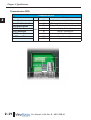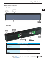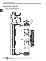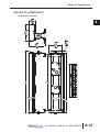
1
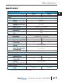
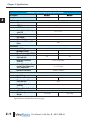
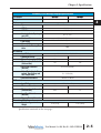
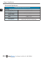
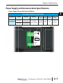
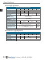
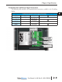
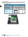
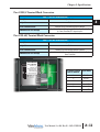
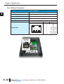
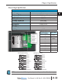
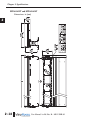
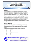
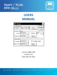
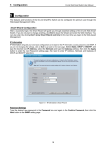
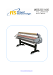
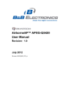
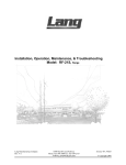
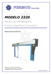
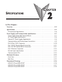
SPECIFICATIONS
CHAPTER
2
In This Chapter...
Overview . . . . . . . . . . . . . . . . . . . . . . . . . . . . . . . . . . . . . . . . . . . . . . . . . . . . . . . . . .2–2
Specifications . . . . . . . . . . . . . . . . . . . . . . . . . . . . . . . . . . . . . . . . . . . . . . . . . . . . . .2–3
Environmental Specifications . . . . . . . . . . . . . . . . . . . . . . . . . . . . . . . . . . . . . . . . . .2–6
Power Supply and Communication Specifications . . . . . . . . . . . . . . . . . . . . . . . . . .2–7
Power Supply Removable Terminal Blocks . . . . . . . . . . . . . . . . . . . . . . . . . . . . . . . .2–7
AC Power Supply Specifications . . . . . . . . . . . . . . . . . . . . . . . . . . . . . . . . . . . . . . . .2–8
External DC Power Supply Requirements . . . . . . . . . . . . . . . . . . . . . . . . . . . . . . . . .2–8
Communication and Discrete Input Connections . . . . . . . . . . . . . . . . . . . . . . . . . . .2–9
RS-232 Port 1 RJ12 Connector . . . . . . . . . . . . . . . . . . . . . . . . . . . . . . . . . . . . . . . .2–10
Port 1 RS232 Terminal Block Connection . . . . . . . . . . . . . . . . . . . . . . . . . . . . . . . .2–11
Port 2 RS-485 Terminal Block Connection . . . . . . . . . . . . . . . . . . . . . . . . . . . . . . .2–11
Port 3 Ethernet Connection . . . . . . . . . . . . . . . . . . . . . . . . . . . . . . . . . . . . . . . . . .2–12
Discrete Input Specifications . . . . . . . . . . . . . . . . . . . . . . . . . . . . . . . . . . . . . . . . .2–13
Communication LEDs . . . . . . . . . . . . . . . . . . . . . . . . . . . . . . . . . . . . . . . . . . . . . .2–14
Mechanical Features . . . . . . . . . . . . . . . . . . . . . . . . . . . . . . . . . . . . . . . . . . . . . . . .2–15
Front View . . . . . . . . . . . . . . . . . . . . . . . . . . . . . . . . . . . . . . . . . . . . . . . . . . . . . . .2–15
Back View . . . . . . . . . . . . . . . . . . . . . . . . . . . . . . . . . . . . . . . . . . . . . . . . . . . . . . .2–15
Dimensional Drawings . . . . . . . . . . . . . . . . . . . . . . . . . . . . . . . . . . . . . . . . . . . . . .2–16
MD4-0112T and MD4-0124T . . . . . . . . . . . . . . . . . . . . . . . . . . . . . . . . . . . . . . . .2–16
MD4-0212T and MD4-0224T . . . . . . . . . . . . . . . . . . . . . . . . . . . . . . . . . . . . . . . .2–17
MD4-0412T and MD4-0424T . . . . . . . . . . . . . . . . . . . . . . . . . . . . . . . . . . . . . . . .2–18
Chapter 2: Specifications
1
2
3
4
5
6
7
8
9
10
11
12
13
14
A
B
C
D
Overview
The ViewMarq LED display is a tri-color completely enclosed unit that is intended to be
controlled over serial RS-232/485 or Ethernet networks by a PLC utilizing ASCII or Modbus.
It is configured using the ViewMarq Software running on a PC over either RS-232/485 or
Ethernet.
The ViewMarq is a fully enclosed NEMA 4/12 indoor use only unit, hose-down rated,
corrosion resistant display. When the supplied wall mount brackets are used and customer
supplied flexible conduit is used for all cables, the message display meets UL508 requirements.
The display may be powered by either 24 VDC or 120/240 VAC nominally.
NOTE: The ViewMarq LED message display can accept either DC power (24 VDC) or AC power
(120 or 240 VAC) but not both simultaneously.
2–2
User Manual, 1st Ed. Rev. B – MD-USER-M
Chapter 2: Specifications
Specifications
1
2
3
4
5
6
7
8
9
10
11
12
13
14
A
B
C
D
ViewMarq 1-Line Message Displays Specifications
Part Number
Description
Display
• Type
• LED Life
• LED Pitch
• Center to Center Spacing of
each LED
• Number of Lines
• Text Height
• Character Set
• Approximate Viewing Distance
AC Electrical
• Input Voltage
• Maximum Current
• Power Consumption (MAX)
• Maximum Inrush Current
(Cold and Hot)
• Input Fuse Protection
(Internal)
• Output Protection for Overcurrent, Over Voltage and
Over Temperature
• Insulation Resistance
DC Electrical
• Input Voltage
• Maximum Current
• Maximum Inrush Current
(Cold and Hot)
• Input Fuse Protection
(Internal)
• Reverse Polarity Protection
Dimensions / Weight
• Enclosure Approximate
Weight
MD4-0112T
MD4-0124T
1 Line X 12 Character
1 Line X 24 Character
LED matrix: Tri-color (Green, Red, Amber)
100,000 hours
0.19 in [5 mm]
0.27 in [7 mm]
1 (Based on 5 x 7 pixel sized characters)
1.25 in, 2 in (Depends on character set selected)
English
100 ft
100-240 VAC (+10% / -15%), 50 / 60 Hz
0.5A
0.8A
22W
38W
25A
26A
Yes (not user replaceable)
Yes – Self Resetting
> 10 MOhms @ 500 VAC
24 VDC (+10% / -15%)
1A
1.5 A
3A
4.5 A
Yes (not user replaceable)
Yes
4.9 lbs [2.2 kg]
9.0 lbs [4.1 kg]
Specifications continued on the next page...
User Manual, 1st Ed. Rev. B – MD-USER-M
2–3
Chapter 2: Specifications
ViewMarq 2-Line Message Displays Specifications
1
2
3
4
5
6
7
8
9
10
11
12
13
14
A
B
C
D
Part Number
Description
Display
• Type
• LED Life
• LED Pitch
• Center to Center Spacing of
each LED
• Number of Lines
• Text Height
• Character Set
• Approximate Viewing Distance
AC Electrical
• Input Voltage
• Maximum Current
• Power Consumption (MAX)
• Maximum Inrush Current
(Cold and Hot)
• Input Fuse Protection
(Internal)
• Output Protection for Overcurrent, Over Voltage and
Over Temperature
• Insulation Resistance
DC Electrical
• Input Voltage
• Maximum Current
• Maximum Inrush Current
(Cold and Hot)
• Input Fuse Protection
(Internal)
• Reverse Polarity Protection
Dimensions / Weight
• Enclosure Approximate
Weight
MD4-0212T
MD4-0224T
2 Line X 12 Character
2 Line X 24 Character
LED matrix: Tri-color (Green, Red, Amber)
100,000 hours
0.19 in [5 mm]
0.27 in [7 mm]
2 (Based on 5 x 7 pixel sized characters)
1.25 in, 2 in, 4 in (Depends on character set selected)
English
200 ft
100-240 VAC (+10% / -15%), 50 / 60 Hz
1A
2A
38W
74W
26A
24A
Yes (not user replaceable)
Yes – Self Resetting
> 10 MOhms @ 500 VAC
24 VDC (+10% / -15%)
2A
3.5A
10.5A
Yes (not user replaceable)
Yes
7.3 lbs [3.3 kg]
Specifications continued on the next page...
2–4
User Manual, 1st Ed. Rev. B – MD-USER-M
13.1 lbs [6.0 kg]
Chapter 2: Specifications
ViewMarq 4-Line Message Displays Specifications
Part Number
Description
Display
• Type
• LED Life
• LED Pitch
• Center to Center Spacing of
each LED
• Number of Lines
• Text Height
• Character Set
• Approximate Viewing Distance
AC Electrical
• Input Voltage
• Maximum Current
• Power Consumption (MAX)
• Maximum Inrush Current
(Cold and Hot)
• Input Fuse Protection
(Internal)
• Output Protection for Overcurrent, Over Voltage and
Over Temperature
• Insulation Resistance
DC Electrical
• Input Voltage
• Maximum Current
• Maximum Inrush Current
(Cold and Hot)
• Input Fuse Protection
(Internal)
• Reverse Polarity Protection
Dimensions / Weight
• Enclosure Approximate
Weight
MD4-0412T
MD4-0424T
4 Line X 12 Character
4 Line X 24 Character
1
2
3
4
5
6
7
8
9
10
11
12
13
14
A
B
C
D
LED matrix: Tri-color (Green, Red, Amber)
100,000 hours
0.19 in [5 mm]
0.27 in [7 mm]
4 (Based on 5 x 7 pixel sized characters)
1.25 in, 2 in, 4 in, 6 in, 8 in (Depends on character set selected)
English
400 ft
100-240 VAC (+10% / -15%), 50 / 60 Hz
2A
2A
74W
123W
24A
9.5A
Yes (not user replaceable)
Yes – Self Resetting
> 10 MOhms @ 500 VAC
24 VDC (+10% / -15%)
3.5A
4A
10.5A
12A
Yes (not user replaceable)
Yes
12.1 lbs [5.5 kg]
22.5 lbs [10.2 kg]
Specifications continued on the next page...
User Manual, 1st Ed. Rev. B – MD-USER-M
2–5
Chapter 2: Specifications
Environmental Specifications
1
2
3
4
5
6
7
8
9
10
11
12
13
14
A
B
C
D
ViewMarq Message Displays Specifications
Environmental
• Storage Temperature
• Operating Temperature
• Humidity
• Enclosure Ratings
• Vibration
• Shock
• Noise Immunity
• Agency Approvals
2–6
–30 to +85 °C (–22 to +185 °F)
0 to 60 °C (32 to +140 °F)
5 – 95% non-condensing
NEMA 12 indoor only, NEMA 4 indoor only
IEC 60068-2-6 (Test Fc)
IEC 60068-2-27 (Test Ea)
EN61131-2:2007
UL508, NEMA 4, NEMA 12, RoHS, REACH
CE (EN61131-2:2007) - Pollution Degree 2, Overvoltage Category II
User Manual, 1st Ed. Rev. B – MD-USER-M
Chapter 2: Specifications
Power Supply and Communication Specifications
Power Supply Removable Terminal Blocks
Power Supply Removable Terminal Blocks
Part Number
Terminal
Connector
AC Power
Removable 3-pin
terminal block
DC Power
Removable 2-pin
terminal block
MD-TERM-SET
Wire Size
Screw
Torque
12-14 AWG
solid or stranded
4.5 in·lbs
(0.5 N·m)
Voltage Current Temperature
Rating Rating
Rating
300V
15A
105 °C
(221 °F)
Ground
Neutral
Line
100-240 VAC
WARNING:
Use only one
power source
24 VDC
0V
24V
User Manual, 1st Ed. Rev. B – MD-USER-M
2–7
1
2
3
4
5
6
7
8
9
10
11
12
13
14
A
B
C
D
Chapter 2: Specifications
AC Power Supply Specifications
1
2
3
4
5
6
7
8
9
10
11
12
13
14
A
B
C
D
AC Power Supply General Specifications
MD4-0112T
Part Number
Input Voltage
0.5A
Maximum Current
22W
Power Comsumption (MAX)
Maximum Inrush Current
25A
(Cold and Hot)
Input Fuse Protection
(Internal)
Output Protection for Overcurrent, Over Voltage and Over
Temperature
25-60 VAC
Under Input Voltage Lockout
No
Over Input Voltage Lockout
MD4-0212T
MD4-0224T
MD4-0412T
MD4-0424T
100-240 VAC (+10% / -15%), 50 / 60 Hz
0.8A
1A
2A
38W
74W
123W
26A
24A
9.5A
40-70 VAC
30-70 VAC
Yes (not user replaceable)
Yes – Self Resetting
40-65 VAC
265-285 VAC
Varistor Plus Input Choke and Passive Filter
Active Power
Factor Correction
AC Mains to SELV
SELV = Secondary Extra Low Voltage (RS232, RS485, Ethernet)
3250 VDC /
2 Seconds
Input Transient Protection
Voltage Withstand (Dielectric)
Insulation Resistance
MD4-0124T
> 10 MOhms @ 500 VAC
External DC Power Supply Requirements
DC Power Supply General Specifications
Part Number
Input Voltage
Maximum Current
Maximum Inrush Current
(Cold and Hot)
Reverse Polarity Protection
2–8
MD4-0112T
MD4-0124T
MD4-0212T
MD4-0224T
MD4-0412T
MD4-0424T
24 VDC (+10% / -15%)
1A
1.5A
3A
4.5A
2A
3.5A
10.5A
Yes
User Manual, 1st Ed. Rev. B – MD-USER-M
4A
12A
Chapter 2: Specifications
Communication and Discrete Input Connections
The following table describes the communication connections available in the ViewMarq
display.
Communications and Discrete Input Connections
Port
Type
Connector
Port 1
RS-232
Port 1 / Port 2
RS-232 / RS-485
Port 3
Ethernet
Port 4
Discrete Inputs
RJ12
Removable 6-pin
terminal block
RJ45
Removable 10-pin
terminal block
Wire Size
Screw Torque
n/a
14-28 AWG
1.7 in·lbs (0.2 N·m)
n/a
14-28 AWG
1.7 in·lbs (0.2 N·m)
RS-232 (Port 1)/
RS-485 (Port 2)
Terminal Block
In 1
In 2
In 3
In 4
CA
In 5
In 6
In 7
In 8
CB
1
2
3
4
5
6
7
8
9
10
Port 2
RS485
5
Port 1
RS232
2
+
SG
TX
RX
RTS
RT
S
RJ12
12
Port1
rt1
RS23
232
RS232
RJ45
Ethernet
Et
et
Discrete Inputs
Terminal Block
RS-232 (Port 1)
RJ12 Connector
Ethernet (Port 3)
RJ45 Connector
User Manual, 1st Ed. Rev. B – MD-USER-M
2–9
1
2
3
4
5
6
7
8
9
10
11
12
13
14
A
B
C
D
Chapter 2: Specifications
RS-232 Port 1 RJ12 Connector
1
2
3
4
5
6
7
8
9
10
11
12
13
14
A
B
C
D
Port1 - RS-232 RJ12 Connector
Description
Specification
Designation
Port 1
Serial Communications
Communication Port Settings
Connector Type
Physical Layer: Non-isolated,
Conforms to RS-232 Communications Interface
2400, 9600,19200, 38400 Data Length: 7/8 bits, Stop Bit: 1 bit, Parity:
None, Even/Odd, No RTS signal
Female RJ12
Pin Number Signal Name
1
Signal GND
2
Not Used
3
RXD
1234 5 6
4
TXD
5
Not Used
6
Signal GND
Port 1 RJ12
(RS-232)
123456
2–10
User Manual, 1st Ed. Rev. B – MD-USER-M
Chapter 2: Specifications
Port 1 RS232 Terminal Block Connection
Port 1 - RS-232 Terminal Block
Description
Specification
Designation
Port 1
Serial Communications
Communication Port Settings
Physical Layer: Non-isolated,
Conforms to RS-232 Communications Interface
2400, 9600,19200, 38400 Data Length: 7/8 bits, Stop Bit: 1 bit, Parity: None, Even/Odd, RTS signal on pin 6
Port 2 RS-485 Terminal Block Connection
Port 2 - RS-485 Terminal Block
Description
Specification
Designation
Port 2
Serial Communications
Communication Port Settings
Physical Layer: Non-isolated,
Conforms to RS485 Communications Interface
9600,19200, 38400 Data Length: 7/8 bits, Stop Bit: 1 bit, Parity:
None, Even/Odd
Port 1 RS-232 /
Port 2 RS-485
RS-485 + (1)
In 1
1
RS-485
-Port
(2)2 +
In 2
2
RS485
Ground
(3)
InSignal
3
3
SG
In 4 RS-232
4 TX (4)
TX
2
CA RS-232
5 RXPort
RX
(5)
RS232
6
RTS
In 5RS-232 RTS (6)
7
In 6
RJ12
8
In 7
Port1
9
In 8
RS232
10
CB
RJ45
Ethernet
6 Position Terminal Signal Name
Block Pin Number
1
RS-485 +
2
RS-485 -
3
Signal Ground
4
RS-232 TX
5
RS-232 RX
6
RS-232 RTS
User Manual, 1st Ed. Rev. B – MD-USER-M
2–11
1
2
3
4
5
6
7
8
9
10
11
12
13
14
A
B
C
D
Chapter 2: Specifications
Port 3 Ethernet Connection
1
2
3
4
5
6
7
8
9
10
11
12
13
14
A
B
C
D
Port 3 - Ethernet
Description
Specification
Standard Specification
Conforms to IEEE802.3
Communication Speed
10/100BASE-T(auto crossover)
Cable Specification
Cat5e
Physical Jack
RJ45, Module jack
Female RJ45
Connector Type
8 765432 1
Pin Number
1
2
3
4
5
6
7
8
Port 3 RJ45
(Ethernet)
87654321
2–12
User Manual, 1st Ed. Rev. B – MD-USER-M
Signal Name
TD+
TDRD+
No Connection
No Connection
RDNo Connection
No Connection
Chapter 2: Specifications
Discrete Input Specifications
Discrete Inputs
Description
Specification
Inputs per Module
Commons per Module
Input Voltage Range
ON Voltage / Current Level
OFF Voltage / Current Level
Maximum Input Current
Input Impedance
OFF to ON Response
ON to OFF Response
Peak Voltage
8 (sinking / sourcing)
2 isolated (4 inputs per common)
10-28 VDC
9 VDC / 3mA
4 VDC / 0.5 mA
13 mA @ 28 VDC
2.2 kohm @ 24 VDC
2 to 9ms
2 to 9ms
30 VDC
Discrete Input
In 1
In 2
In 3
In 4
CA
In 5
In 6
In 7
In 8
CB
1
2
3
4
5
6
7
8
9
10
10 Position Terminal
Block Pin Number
(1) Input 1
(2) Input 2
(3) Input 3
(4) Input 4
(5) Common A
(6) Input 5
(7) Input 6
(8) Input 7
(9) Input 8
(10) Common B
Port 2 +
RS485 SG
TX
Port 2
RX
RS232
RTS
RJ12
Port1
RS232
RJ45
Ethernet
Input 1
2
Input 2
3
Input 3
4
Input 4
5
Common A
6
Input 5
7
Input 6
8
Input 7
9
Input 8
10
Common B
Input 1
Input 1
Input 2
Input 2
Input 4
Input 3
-
Input 3
+
Input 4
Common A
Common A
Input 5
Input 5
Input 6
Input 6
Input 8
Common B
Input 7
-
Input 7
+
+
1
Sinking Input Wiring
Sourcing Input Wiring
+
Signal Name
Input 8
Common B
NOTE: In order to maintain UL508 rating, discrete inputs must be powered from a Class 2 power supply.
User Manual, 1st Ed. Rev. B – MD-USER-M
2–13
1
2
3
4
5
6
7
8
9
10
11
12
13
14
A
B
C
D
Chapter 2: Specifications
Communication LEDs
Communication LEDs
LED
Color Silkscreen Label
Ethernet Speed
Ethernet Link Status Condition
RS-232 Request to Send
RS-232 Receive Data
RS-232 Transmit Data
RS-485 Receive Data
RS-485 Transmit Data
Error
SPD
Green
Meaning
OFF = 10M Connection, ON = 100M Connection
LNK
OFF - No link, ON = Link, Blinking = Network Activity
RTS
Blinking = RS232 is attempting to establish connection
RX1
Blinking = Receiving Data
TX1
Blinking = Transmitting Data
RX2
Blinking = Receiving Data
TX2
Blinking = Transmitting Data
ERR
Communication Error
LNK SPD
2–14
RJ45
RJ
45
Ethe
Et
hern
he
rnet
Ethernet
RJ12
RJ
12
Port
Po
rt1
Port1
RS23
RS
232
RS232
ERR TX2 RX2 TX1 RX1 RTS
Port
Po
rt 2 +
RS48
RS
485 485
RS485
SG
TX
Port
Port 2
RX
RS232
RS23
RS
232 RTS
232
RT
1
2
3
4
5
6
7
8
9
10
11
12
13
14
A
B
C
D
User Manual, 1st Ed. Rev. B – MD-USER-M
Chapter 2: Specifications
Mechanical Features
Front View
End Cap
Aluminum
Extrusion
End Cap
Lens
Back View
End Cap
Aluminum
Extrusion
End Cap
Communication
Connection
Opening
Power Connection
Opening
ViewMarq Housing Materials
Aluminum Extrusion
End Caps
End Cap Gaskets
Back Covers
Back Cover Gaskets
Lens
Lens Seal
AL6063-T5 Black Anodized
Polycarbonate
Silicon
Polycarbonate
Silicon
Polycarbonate
Silicon
User Manual, 1st Ed. Rev. B – MD-USER-M
2–15
1
2
3
4
5
6
7
8
9
10
11
12
13
14
A
B
C
D
Chapter 2: Specifications
1
2
3
4
5
6
7
8
9
10
11
12
13
14
A
B
C
D
Dimensional Drawings
MD4-0112T and MD4-0124T
Dimensions: in [mm]
2–16
User Manual, 1st Ed. Rev. B – MD-USER-M
Chapter 2: Specifications
MD4-0212T and MD4-0224T
1
2
3
4
5
6
7
8
9
10
11
12
13
14
A
B
C
D
Dimensions: in [mm]
User Manual, 1st Ed. Rev. B – MD-USER-M
2–17
Chapter 2: Specifications
MD4-0412T and MD4-0424T
1
2
3
4
5
6
7
8
9
10
11
12
13
14
A
B
C
D
Dimensions: in [mm]
2–18
User Manual, 1st Ed. Rev. B – MD-USER-M