1
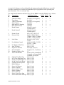
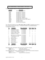
Sentinel I21/B21/F21
Serial Communications
APPLICATION BULLETIN #105A
June 6, 2002
PURPOSE
This document provides the hardware and protocol information needed to successfully
communicate with the Sentinel I-21/B-21/F21 instruments through the RS232 and/or RS485
serial ports. The RS232 port is designed to allow an IBM PC (or compatible) to communicate
with one I-21/B-21/F-21 instrument. The RS485 port is designed to allow an IBM PC (or
compatible) to communicate with multiple I-21/B-21/F-21’s (as would be required for a data
collection system).
The serial communication ports allow access to all internal parameter locations, allowing
remote setup of the instrument. Remote operation of the Sentinel I-21/B-21/F-21 instruments is
performed through the dedicated I/O. The serial ports also have access to past test results.
Cincinnati Test Systems retains the right to change any of the characteristics of the Sentinel
instruments, including these serial communications features, at any time.
If you intend to implement a computer based communications system and do not have
experience writing programs that serially communicate with instrumentation, you may want to
consider purchasing technical assistance from CTS. Please contact us at 513-367-6699 for
more information.
RS232 HARDWARE
The RS232 port is hardwired to be identical to most standard IBM PC compatible serial
communications ports. In most cases, hookup to an IBM PC compatible requires only a Null
Modem cable (available from C.T.S. and most computer stores). In some cases, however, the
PC manufacturer may not have adhered to the IBM standard and a custom cable may be
required.
The hardwire interconnect on the front panel DB9 connector is described below:
PIN
1
2
3
4
5
6
7
8
9
FUNCTION
DCD
RD
SD
DTR
shield ground (not a required hookup)
DSR
RTS
CTS
NC
This port operates using the following transmission format:
1.
9600 Baud
2.
8 bit data
3.
No parity
4.
1 stop bit
RS485 HARDWARE
The RS485 port implemented in the Sentinel I-21/B-21/F-21 instrument conforms to the RS485
standards (serial, multidrop, differential voltage). To simplify customer written software, this
port supports half duplex communication only (e.g. it permits communication in only one
direction at any given moment). As a result, the network server (typically an IBM PC) will act
as a master, and each Sentinel instrument on the network will be slaves. In this configuration,
the master will broadcast an address and message over the network and then wait for a
response. The Sentinel instrument with that address will respond by broadcasting the
appropriate reply. All other instruments will be silent.
The hardwire interconnect on the six conductor RJ12 connector (located on the bottom circuit
board) is described below:
PIN
FUNCTION
1
- transmit
2
ground
3
+ transmit
4
+ receive
5
ground
6
- receive
To create a complete system, the master must be wired to the slaves through a network. In the
diagram below, an IBM PC (the master) with an external RS232 to RS485 converter module is
connected to a network. The network has “Y” taps and a drop for each instrument. The last
“Y” has a terminator to minimize signal reflection. A network similar to the one shown can be
over 1000 feet long in normal factory settings. In facilities with very electrically noisy
equipment (large welders, induction heat treat equipment, etc.), signal repeaters may be
required.
This port operates using the following transmission format:
1.
9600 Baud
2.
8 bit data
3.
No parity
4.
1 stop bit
5.
Xon/Xoff handshaking supported
Application Bulletin #105A
2
RS232 SOFTWARE
A. Writing to the Sentinel I-21/B-21/F-21 instruments
To write information from a computer to the Sentinel instrument’s RS232 port, the computer
must transmit a specially formatted data packet. This communication format is:
^B <Command String>, <Data ID Number>, <Data Value> ^C
Where: ^B is Control B (02H)
^C is Control C (03H)
< > and spaces are for description purposes only and are not
transmitted.
, is a required character
Command String is 6 ASCII characters maximum
Data ID Number is 3 ASCII characters maximum
Data Value is usually a floating point number but can also be an
ASCII string
Floating point numbers are 12 ASCII characters maximum, digits 0-9,. , E, and -. Maximum
exponent is + 38. Syntax is the same as Microsoft Basic. Valid floating point numbers are 3456, 34.4567, -4.56789E-34, 456780, 1E23. Imbedded spaces within the floating point
number are not allowed. Not all messages will contain Data ID Numbers and/or Data Values.
The valid Command Strings are as follows:
Description
Command
WRP1
Write to Part 1 locations
WRP2
Write to Part 2 locations
WRP3
Write to Part 3 locations
WRP4
Write to Part 4 locations
WRP5
Write to Part 5 locations
WRP6
Write to Part 6 locations
WRP7
Write to Part 7 locations
WRPS
Write to SELF TEST locations
WRMS
Write to the MISC locations (and counters)
The valid Data ID Numbers and Data Values for all PART (WRP1 - WRP7) and SELF TEST
(WRPS) Commands are as follows: (G1- original version, G2 – Generation II)
ID
Description
Data Value Ranges
I21G1 I21G2 F21
1
Clamp Timer
.1 to 9999
x
x
x
2
Seal Timer
.1 to 9999
x
x
x
3
Gross Timer
.1 to 9999
x
x
x
4
Fill Timer
.1 to 9999
x
x
x
5
Stabilize Timer
.1 to 9999
x
x
6
Test Timer
.1 to 9999
x
x
x
7
Exhaust Timer
.1 to 9999
x
x
x
Application Bulletin #105A
3
ID
8
9
10
11
12
13
14
15
16
17
18
23
24
25
26
27
31
32
22
21
20
19
33
34
30
29
28
35
36
37
38
39
40
41
42
43
44
45
46
47
Description
Data Value Ranges
I21G1 I21G2 F21
Gross2 Timer
.1 to 9999
x
x
x
Fill2 Timer
.1 to 9999
x
x
x
Stabilize2 Timer
.1 to 9999
x
x
Test2 Timer
.1 to 9999
x
x
x
Exhaust2 Timer
.1 to 9999
x
x
x
Relax Timer
.1 to 9999
x
x
x
Min. Test Pressure .0000 to 99999
x
x
x
Max. Test Pressure .0001 to 99999
x
x
x
No-Leak Loss
.0000 to 99999
x
x
Hi Limit Loss
.0001 to 99999
x
x
Max. Cal Loss/Flow .0001 to 99999
x
x
x
Min. Test 2 Pressure .0000 to 99999
x
x
x
Max. Test2 Pressure .0001 to 99999
x
x
x
No-Leak Loss 2
.0000 to 99999
x
x
Hi Limit Loss 2
.0001 to 99999
x
x
Max.Cal Loss2/Flow2 .0001 to 99999
x
x
x
Reject Rate
.001 to 9999
x
x
x
Orifice
.001 to 9999
x
x
Max. Res Allowed .001 to 9999
x
x
Lo Limit Leak
-.01 to –999
x
x
Zero Shift Percent
00 to 99
x
x
x
Zero Shift Quantity 5 to 999
x
x
x
Reject Rate 2
.001 to 9999
x
x
x
Orifice 2
.001 to 9999
x
x
Max Res Allowed 2 .001 to 9999
x
x
Lo Limit Leak 2
-.01 to –999
x
x
Zero Shift Percent 2 00 to 99
x
x
x
Part Name
up to 12 ASCII char x
x
x
Resolution*
.001 to 9999
x
x
Resolution 2*
.001 to 9999
x
x
Zero Shift Value*
-9999 to 99999
x
x
x
Zero Shift Value 2* -9999 to 99999
x
x
x
Low Limit Loss
x
Low Limit Loss 2
x
Calibration Flow
x
Calibration Flow 2
x
Target Pressure
x
Target Pressure 2
x
Min Cal Flow
-999 to 9999
x
Min Cal Flow 2
-999 to 9999
x
Timers values must be in 0.1 second increments.
Percentages can range from 0 to 99 in 1% increments
An x denotes which instrument has the feature.
Application Bulletin #105A
4
An asterisk (*) denotes a value calculated by the instrument through calibration or zero shift
procedures and therefore would not be transmitted by the programmer when uploading new
part information. This is “read only” data.
The valid Data ID Numbers and Data Values for the MISC Command (WRMS) are as follows:
ID
Description
Valid Data Values
I21G1 I21G2 F21
1
2
3
4
5
6
7
8
9
10
11
12
13
14
15
16
20
21
22
23
24
25
26
27
28
29
30
31
32
33
34
Trans Zero Range
Trans Span
Trans 2 Zero Range
Trans 2 Span
Runs until Cal Warning
Runs until Cal Error
Result Format
0 to 9999 (6.0 is typical)
0 to 9999
0 to 9999 (6.0 is typical)
0 to 9999
1-999999
1-999999
0 (leak), 1 (press),
2 (leak & press)
Result Format 2
0 (leak), 1 (press),
2 (leak & press)
Pneum Circuit
0 (S), 1 (F), 2 (D), 3 (T)
Pressure Units
0 (psi), 1 (kPa), 2 (bar),
3 (Mpa), 4 (iHG), 5 (mHg),
6 (iWC), 7 (mbr), 8 (atm)
Leak Units
0 (ccm), 1 (ccs), 2 (cis),
3 (cch)
Use Machine Control
0 (NO), 4 (YNF), 5 (YCF),
6 (YSF), 7 (YBF)
Is 2 Inputs to Start Test
0 (no), 1 (yes)
Anti Tie Down
0 (no), 1 (yes)
Negative Leak Parts
0 (accept), 1 (reject)
Set Current Part
0-6 (parts 1-7), 7 (self test)
Number of Parts to Test
1-7
Auto Calib Method
0 (auto, orifice in manifold)
1 (manual, orif in manifold)
2 (manual, orif in part)
Update ZS on Part Chg
0 (no), 1 (yes)
Is 1st Test a Blockage Test 0 (no), 1 (yes)
Is 2nd Test a Blockage Test 0 (no), 1 (yes)
Is 2nd Test if 1st is Reject
0 (no), 1 (yes)
Unclamp Part if Rejected
0 (no), 1 (yes)
RS485 Address
1-32
Secure Cal Process
0 (no), 1 (yes)
Secure Test Info
0 (no), 1 (yes)
Secure Orifice Value
0 (no), 1 (yes)
Secure Counters
0 (no), 1 (yes)
Secure Self Test
0 (no), 1 (yes)
Secure Trans Zero, Span
0 (no), 1 (yes)
Secure Runs until Cal Req’d 0 (no), 1 (yes)
Application Bulletin #105A
5
x
x
x
x
x
x
x
x
x
x
x
x
x
x
x
x
x
x
x
x
x
x
x
x
x
x
x
x
x
x
x
x
x
x
x
x
x
x
x
x
x
x
x
x
x
x
x
x
x
x
x
x
x
x
x
x
x
x
x
x
x
x
x
x
x
x
x
x
x
x
x
x
x
x
x
x
x
x
x
x
x
ID
35
36
37
38
39
40
41
42
43
44
45
46
47
48
49
50
51
52
53
54
55
Description
Date and Time
Password
Secure Chg part function
Exhaust Output operation
Valid Data Values
I21G1 I21G2 F21
See Command Disc
x
x
x
4 ASCII Digits
x
x
x
0(no), 1(yes)
x
x
x
0(exhaust), 1(Acc),
x
x
x
2(Rej)
Software Version
4 ASCII Characters
x
x
x
Hardware Type
1(I21), 2(F21)
x
x
< Low Limit 1
0(Reject), 1(Accept)
x
x
Between Limits 1
0(Reject), 1(Accept)
x
x
>High Limit 1
0(Reject), 1(Accept)
x
x
<Low Limit 2
0(Reject), 1(Accept)
x
x
Between Limits 2
0(Reject), 1(Accept)
x
x
>High Limit 2
0(Reject), 1(Accept)
x
x
Utility Input
0(Hold), 1(Part Present)
x
x
Hold Limit Outputs past eot 0(No), 1(Yes)
x
x
Utility Output
0(In 2nd Test), 1(In Cal)
x
x
2(Gross Tmr), 3(Test Tmr)
Test 1 Style
0(Leak), 1(Flow)
x
Test 2 Style
0(Leak), 1(Flow)
x
Max Transducer Zero
Millivolts
x
Transducer Span
0(1000ccm), 1(6000ccm)
x
2(Custom)
Max Transducer 2 Zero
Millivolts
x
Transducer 2 Span
0(1000ccm), 1(6000ccm)
x
2(Custom)
Commands associated with “Parts” (WRP1 - WRP7 and WRPS) help transfer data associated
with the individual parts being tested. To run a leak (or flow) test, all appropriate Part Data ID
Numbers and Values must be transmitted. The programmer does not have to transmit values
for Parts that won’t be used. Commands associated with “MISC” help transfer data associated
with the instrument configuration. The instruments will use default values (see user manual)
unless the programmer chooses to overwrite the location.
The following line will write the value “1.5 sec” to the Part 3 Fill Timer location:
^BWRP3, 4,1.5^C
The following line will change the auto calibration method from its default value:
^BWRMS, 21,2^C
B. Reading from the Sentinel I-21/B-21/F-21 instrument
To read information from the Sentinel instrument, the computer must transmit a “read request”
packet. The instrument will respond with a specially formatted reply containing the requested
information. The read request format is:
^B <Command String>, <Data ID Number> ^C
The Sentinel instrument reply format is:
Application Bulletin #105A
6
^B <Command String>, <Data ID Number>, <Data Value> ^C
The valid Command Strings for reading information are as follows:
Command
Description
RDP1
Read the Part 1 locations
RDP2
Read the Part 2 locations
RDP3
Read the Part 3 locations
RDP4
Read the Part 4 locations
RDP5
Read the Part 5 locations
RDP6
Read the Part 6 locations
RDP7
Read the Part 7 locations
RDPS
Read the SELF TEST locations
RDMS
Read the MISC locations (and counters)
RDAT
Read the counters
RDTR
Read the test data
RESP
Reset the test data pointer
The valid Data ID Numbers for the PART, SELF TEST and MISC Commands are the same as
in the writing procedure shown above. Valid Data ID Numbers for all COUNT (RDAT)
Commands are as follows:
Description
Data Value Ranges
I21G1 I21G2 F21
ID
1
Leaks Counter
0 to 999999
x
2
Severe Leaks Counter
0 to 999999
x
3
Total Rejects Counter
0 to 999999
x
x
x
4
Total Accepts Counter
0 to 999999
x
x
x
5
Negative Leaks Counter
0 to 999999
x
6
Stops/Errors Counter
0 to 999999
x
x
x
7
Runs Since Last Calibration 0 to 999999
x
x
x
8
Total Runs Since New
0 to 999999
x
x
x
9
<Low Limit 1
0 to 999999
x
x
10
Between Limits 1
0 to 999999
x
x
11
>High Limit 1
0 to 999999
x
x
12
Severe Leak 1
0 to 999999
x
x
13
<Low Limit 2
0 to 999999
x
x
14
Between Limits 2
0 to 999999
x
x
ID
Description
Data Value Ranges
I21G1 I21G2 F21
15
>High Limit 2
0 to 999999
x
x
16
Sever Leak 2
0 to 999999
x
x
The following lines will read the value from the Part 3 Fill Timer location:
^BRDP3, 4^C
(sent by the computer)
^BRDP3, 4,1.5^C
(response from the instrument)
The following line will read the Total Runs Since New register from the Sentinel instrument:
^BRDAT, 8^C
(sent by the computer)
^BRDAT, 8,21433^C
(response from the instrument)
Application Bulletin #105A
7
A similar strategy is used to read the test data except that Data ID is not required. The reply
format depends upon the model being used. The read request format is:
^BRESP^C
^BRDTR^C
(sets the read pointer to the most recent data)
(requests the test data being pointed at)
For versions S and F, the instrument reply format is:
^BRDTR, <Part Number>, <Loss>, <Zshift>, <Flow>, <Acc/Rej> ^C
For versions D and T, the instrument reply format is:
^BRDTR, <Part Number>, <Loss>, <Zshift>, <Flow>, <Acc/Rej>,
<Loss2>, <Zshift2>, <Flow2>, <Acc/Rej2> ^C
The pointer is automatically advanced one location with each test data read (RDTR). In a
typical application, the pointer would initially be reset (RESP) to the most recent data. This
would be followed by multiple reads of the test results (RDTR).
The following program segments, written in Basic, are intended to demonstrate typical
communications with the Sentinel instruments. In all cases, these fictitious “programs” reside
in an IBM PC. The first example writes the value “1.5” to the Part 3 Fill Timer location:
100
200
700
OPEN “COM2: 9600,N, 8,1,CS, DS, CD” FOR RANDOM AS #1
PRINT #1, “βWRP3, 4,1.5χ"
CLOSE #1
This example will read part 5’s Leak Loss value:
300
400
500
600
700
PRINT #1, “βRDP5, 17χ"
t! = TIMER
WHILE TIMER - t! < .06
WEND
A$ = INPUT$(LOC (1), #1)
The delay allows time for the data to transfer from the instrument to the computers COM port.
The COM port is then read by the program.
The next example will read the six most recent test results from the instrument:
800
PRINT #1, “βRESPχ"
900 FOR I = 1 TO 6
1000
PRINT #1, “βRDTRχ"
1100
t! = TIMER
1200
WHILE TIMER - t! < .06
1300
WEND
Application Bulletin #105A
8
1400
A$ = INPUT$(LOC (1), #1)
1500
PRINT “PART”; I, “RESULT”; A$
1600 NEXT I
Versions D and T will return a string that is typically longer than the IBM COM port buffer. In
this case, multiple INPUT instructions or other techniques will be needed.
RS485 SOFTWARE
Communications through the RS485 port is very similar to the RS232 port except that a node
address is added to the message. The communication format is:
^A <Node Address> ^B <Command and Data Parameters> ^C
Where: Node Address is two ASCII digits max (1 to 31)
The Commands and Data Parameters are identical to those used in the RS232 Software section
above. The Node Address must correspond to the address set in the instrument.
C.G./G.G.
Rev 1
Application Bulletin #105A
9