1
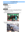
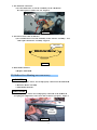
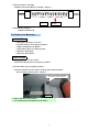
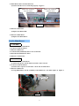
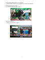
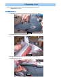
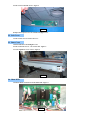
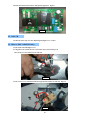
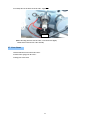
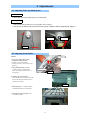
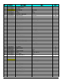
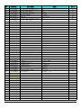
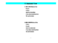
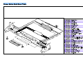
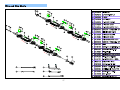
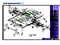
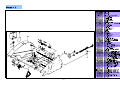
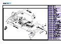
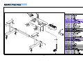
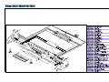
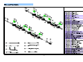
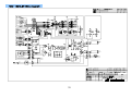
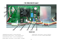
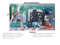
ROLL LAMINATOR
Service Manual
www.royalsovereign.com
Table of Contents
1. Safety Precautions
2. Troubleshooting
………………………………………………………………………
……………………………………………………………………………
2 ~ 2
3 ~ 7
2.1) Rollers Not Heating ………………………………………………………………………………
3 ~ 4
2.2) Rollers Over Heating ………………...……………………………………………………………
4 ~ 5
2.3) Rollers Not Running ……………….………………………………………………………………
5 ~ 6
2.4) No Main Power ……………………..………………………………………………………………
6 ~ 7
3. Replacing Parts ………………………………………………………………………………
8 ~ 11
3.1) Right Cover …………………………………………………………………………………………
8 ~
3.2) Left Cover
…………………………………………………………………………………………
9 ~ 9
3.3) Rear Cover …………………………………………………………………………………………
9 ~ 9
3.4) Main PCB ……………………………………………………………………………………………
9 ~ 10
3.5) Sub PCB ………………………………………………………………………………………………
10 ~ 10
3.6) Heaters ………………………………………………………………………………………………
10 ~ 11
3.7) Cross Cutter …………………………………………………………………………………………
11 ~ 11
4. Adjustments
……………………………………………………………………………………
4.1) Adjusting Take-Up Shaft Speed
4.2) Adjusting Front Roller
9
12 ~ 12
……….…………………………………………………………
12 ~ 12
……………………………………………………………………………
12 ~ 12
5. Installation of Options
……………………………………………...……………………
6. Parts List …………………………………………………………………………………………
13 ~ 13
14 ~ 20
6.1) RSC-1650LS Parts List ………………………………………………………………………………
14 ~ 16
6.2) RSC-1650LSH Parts List ……………………………………………………………………………
17 ~ 20
7. Exploded Drawings
………………………………………………………………………
21 ~ 33
7.1) RSC-1650CF Whole Exploding Drawing and Part Exploding Drawing ……………………
22 ~ 27
7.2) RSC-1650HF Whole Exploding Drawing and Part Exploding Drawing ……………………
28 ~ 33
8. Wire Diagram
…………………………………………………………………………………
34 ~ 39
1. Safety Precautions
Failure to comply any of the following safety procedures could result in serious injury.
Please read the instructions carefully and keep for future reference.
1. Only a licensed electrician should install wiring and outlet for the laminator.
2. Ensure the unit is plugged into a properly grounded outlet with the correct
3 ~ 7
voltage.
3. Keep hands and clothing (ie.Neckties) away from the rollers. The rollers have pinch
points that can trap body parts or clothing and cause serious injury.
Safety Precaution
4. Keep flammable and wet objects away from the machine.
5. Place machine on a level surface.
6. Avoid excessive sunlight, humidity and extreme temperatures.
7. Ensure the unit is turned off, cooled, and unplugged from the outlet prior to
moving and/or repairing.
9 ~ 10
8. Keep out of reach of children.
9. Only Royal Sovereign authorized maintenance and service technicians
10 should
~ 11
make repairs.
11 ~ 11
10. Do not attempt to laminate items that exceed total recommended material
thickness for the unit.
12 ~ 12
11. When cleaning the machine, don't use flammable sprays or materials.
12 ~ 12
12. Do not touch the rollers when they are hot or place foreign objects inside the
12 ~ 12
machine.
13. Do not cover the surface of the machine until the machine has completely cooled.
13 ~ 13
14 ~ 21
14 ~ 17
18 ~ 21
22 ~ 36
2
2. Troubleshooting
2.1 Rollers Not Heating (RSC-1650LSH Only)
CAUSES
1. Disconnected Heater Wire.
2. Defective T/Fuse.
3. Defective Bi-metal.
4. Defective Heater Assembly.
5. Defective Main PCB.
MEASURES
NOTE: Below steps require you to disassemble the Right, Left,
and/or Rear Covers. (Refer to the "Replacing Parts" section)
Follow the below steps in order.
1. Disconnected Heater Wire.
a) Check to make sure that the heater wire is connect to the Main PCB. Figure 1
Heater Wires
Figure 1
2. Defective T/Fuse.
a) Use the multi-tester to check the continuity on the "Wire-T/Fuse".
If it fails replace the Wire-T/Fuse. Figure 2
WIRE-T/FUSE
23 ~ 29
30 ~ 36
37 ~ 42
Figure 2
3
3. The Bi-metal is defective.
a) Use the multi-tester to test the continuity on the "Bi-Metal".
If it fails replace it with a new one. Figure 3
Bi-metal
Figure 3
4. The heater in the roller is defective.
a) Use a multi-tester to test the continuity on the "Heater Assembly". If it
fails replace the Heater Assembly. Figure 4
HEATER
Figure 4
5. Main PCB is defective
a) Replace Main PCB.
2.2) Rollers Over Heating
(RSC-1650LSH Only)
CAUSES
1. The temperature sensor wire is improperly connected to the SUB-PCB.
2. Defective Heater Assembly
3. Main PCB is defective
MEASURES
1. If the temperature sensor wire is improperly connected to the SUB-PCB.
a) Unplug the temperature sensor wire and reconnect it properly. Figure 1
WIRE
SENSOR
Figure 1
4
2. Defective Heater Assembly
a) Replace the broken Heater Assembly. Figure 2
Figure 2
Broken
3. Main PCB is defective
a) Replace Main PCB.
2.3) Rollers Not Running
CAUSES
1. Emergency Switches are Active.
2. Pressure Plate is not in Proper Position.
3. Film is Jammed on the Rollers.
4. Main Motor Wires are Disconnected.
5. Defective Main PCB.
6. Defective Main Motor.
MEASURES
1. Emergency Switch is (are) Active.
a) Deactivate front and rear emergency switches.
2. Pressure Plate is not in Proper Position.
a) Ensure that the Pressure Plate is in the proper position and the
Pressure Plate switch is active. Figure 1
Pressure Plate Switch
Figure 1
3. Film is Jammed on the Rollers.
a) Carefully un-jam the film from the rollers.
5
4. Main Motor Wires are Disconnected.
a) Ensure that the wire is connected properly. Figure 2
Motor wire connector
from the PCB
Motor wire connector
from the Motor
Figure 2
5. Defective Main PCB.
a) Replace the Main PCB.
6. Defective Main Motor.
a) Replace the Main Motor.
2.4) No Main Power
CAUSES
1. Main Power is Not Turned On.
2. No Power from the Outlet.
3. Defective Main Fuse.
4. Control Panel (Sub-PCB) Wire is Not Connected.
5. Disconnected Main Power Wire.
6. Defective Transformer.
MEASURES
1. Main Power is Not Turned On.
a) Turn on the power switch which is located on the rear left.
2. No Power from the Outlet.
a) Ensure there is power on the outlet - check the circuit breaker.
3. Defective Main Fuse.
a) Using Multi-Meter test the continuity of the Main Fuse. If it fails, replace it. Figure 1
Main Fuse
Figure 1
6
4. Control Panel (Sub-PCB) Wire is Not Connected.
a) Ensure that the control wires are connected to the Control Panel (Sub-PCB).
5. Disconnected Main Power Wire.
a) Connect the Main Power wires. Figure 2
Main Power wires
Figure 2
6. Defective Transformer.
a) Replace the Transformer. Figure 3
Transformer
Figure 3
7
3. Replacing Parts
NOTE : Before replacing any parts, ensure that the machine is turned off and
unplugged from the outlet.
3.1 Right Cover
1. Using Philips Screw Driver, loosen the screw on the Pressure Lever. Figure 1
Figure 1
2. Take out the four screws as shown in Figure 2.
Figure 2
3. Disconnect the temperature sensor (RSC-1650LSH only) and control wires
from the Sub-PCB. Figure 3
Figure 3
8
4. Take out two Sub-PCB screws. Figure 4
Figure 4
5) Repeat the steps in reverse to assemble the Right Cover.
3.2 Left Cover
1. Take out four screws on the Left Cover.
3.3 Rear Cover
1. Disassemble the Left and Right Covers.
2. Take out the side screws - one on each side. Figure 5
3. Loosen eight Rear Cover screws. Figure 5
Figure 5
3.4 Main PCB
1. Pull out all the connectors from the main PCB. Figure 6
Figure 6
9
2. Detach the main PCB from the 4 white plastic supporters. Figure 7
Figure 7
3.5 Sub PCB
1. Follow the same steps as in the "Replacing the Right Cover" section.
3.6 Heaters (RSC-1650LSH Only)
1. Take off the Left and Right Covers.
2. Using pliers (one to hold and one to loosen the nut) as shown in Figure 8,
take out the two 5/16 (8mm) nuts on each side.
Figure 8
3. Take out two screws and disassemble the upper heater bracket on each side. Figure 9
Figure 9
10
4. Carefully take out the heater from the roller. Figure 10
Figure 10
* When inserting the heater into the roller, rotate the heater slightly
and the heater will enter the roller smoothly.
3.7 Cross Cutter
1. Disassemble the nut from the frame-cutter.
2. Unfasten the spring from the cutter .
3. Change the cutter-knob.
11
4. Adjustments
4.1 Adjusting Take-Up Shaft Speed
CAUSES:
1. Main rollers and Take-Up Shaft speed is not synchronized.
MEASURES:
1. Take out the Take-Up Shaft Cover by loosing three screws. Figure 1
2. Use a 11/16" (17mm) wrench to loosen (increases speed) or tighten (reduces speed) the bolt. Figure 2
Decrease
Figure 1
Increase
Figure 2
4.2 Adjusting Front Roller
Clockwise
Pressure
• Use 5/16” or 8mm Allen wrench
to adjust the roller pressure:
Clockwise – Increase pressure.
Counter Clockwise – Decrease pressure.
(Figure 3)
1. Using Push-Pull Scale , measure
5 spots as shown on Figure 4 & 5:
Front roller should read between 2-3
on the gauge
Counterclock
i
Figure 3
2. Checking for over all tension –
when the machine is running, check that
the top and the bottom films are fed in
without any wrinkles.
Figure 4
3. Laminating Test – Laminate samples
with different thickness of substrates.
4. Check above steps 2 through 3 with
1.5mil & 5mil films.
Figure 5
12
5. Installation of Options
Note: Below options are to be installed by an authorized RS reseller.
Installation of the Front Feeder Option (Includes 2 brackets, one spindle, and mounting hardware).
1. Install the Front Feeder to the inside of the front frames
using four 9/16” hexagon bolts on each side (Figure 1).
3 ~ 7
Figure 1
Installing the Rear Rewinder Option (Includes motorized winder, bracket, one spindle,
and mounting hardware).
1. Remove the left and right covers by using a Phillips
screwdriver (four screws on each side cover) (Figures 1 & 2).
9 ~ 10
Figure 1
Figure 2
2. Remove the lever knob screw and lever (Figure 3).
Figure 3
3. Remove the rear cover by removing all 10 screws
(4 top, 4 bottom, and 1 on each side) (Figure 4 & 5).
Figure 4
Figure 5
4. Disassemble the power switch bracket and place the left rewinder
(included in the option kit). Then, reinstall the power switch bracket (Figure 6).
Figure 6
5. Install the right rewinder on the outside of the frame and
connect the motor wire to the rear wire (Figures 7 & 8).
6. Reinstall the rear cover.
7. Reinstall the side covers.
8. Reinstall the lever knob and screw.
13
Figure 7
Figure 8
6.Parts List
6.1 RSC-1650LS Parts List
RSC-1650LS
No.
Part No.
1
2
3
4
5
6
7
8
9
10
11
12
13
14
15
16
17
18
19
20
21
22
23
24
25
26
27
28
29
30
31
32
33
34
35
36
37
38
39
40
41
42
43
44
44-1
44-2
13500X005A
13500X006A
WSB13038D2
212LR1012A
BHE08015D2
212LR1011A
WSB08016D2
BHE08065D2
365LR4004A
23300X008A
013LR2118A
34000S010A
MBC04008D2
013LR3002Q
WSB05013D2
MBC05018D2
350LR3038A
23200X001A
21000S029A
014LR1003B
TFH04018D2
381LR4009A
122LR4008A
12200X043A
013LR2116D
122LR4100A
133LR2030A
120LR3035D
120LR4002B
MFC04008D2
021LR3006A
140LR4037A
147LR4002A
12200X022A
WPB15010D2
138LR4002A
032LR4020A
SKE04010B6
SKE04015B6
12200X004A
WPB05030H8
RIV05013E8
013LR2117D
380LR4001A
380CR4007A
380CR4004A
Part Name
Spec.
CASTER-STAND1
CASTER-STAND2
WASHER-SPRING
STAND-FRAME
BOLT
STAND-CENTER
WASHER-SPRING
BOLT
SWITCH-FOOT ASS'Y
CABLE GRAND
FRAME-BASE
POWER-TRANSFORMER
SCREW-BH
FRAME-CUTTER
WASHER-SPRING
SCREW-BH
PCB-MAIN ASS'Y
SUPPORT-BRACKET PCB
MOTOR-MAIN
TABLE-FRONT
SCREW-FH
WIRE-TAKE UP
BUSH-ROLLER LAMI,LO
DU-BUSH
FRAME-FRONT
BUSH-ROLLER,LAMI UP
ROLLER-LAMI
SHAFT-CAM
SHAFT-TAKE UP
SCREW-FH
BRACKET-CLAMPER LEVER
HOLDER-SHAFT,T
PAD-TENSION
BEARING-RADIAL
WASHER-PLAIN
SPRING-TENSION
SHEET-PRESSURE
SCREW-SET
SCREW-SET
DU BUSH
WASHER-PLAIN
BRINDER-RIVET
FRAME-MIDDLE
POWER-CORD EU
POWER-CORD UK
POWER-CORD CUL
2"
2"
SWRH φ13.2*3.8T
SPCC
M8*15
SPCC
SUS27
M8*65
SPCC
AC220V-230V 50/60Hz
M4*8 SUS27
AL6063
5.1*1.3T
M5*18 SUS27
NYLON
36V 60W 75:1
AL6063
M4*18
S45C
40*35
SPCC
S45C
S45C
S45C
M4*8 SUS27
ABS
S45C
LEATHER
NTB
15.5*18*1.0T
Φ3.8
PC 0.3T
M4*10 FZB
M4*15 FZB
10*10
11.8*5*3T
AL
SPCC
AC230 16A
AC240V 13A
AC125V 15A
14
Qt'y
2
2
4
2
8
1
12
7
1
2
1
1
22
1
26
2
1
4
1
1
16
1
2
4
1
2
2
1
1
8
1
1
1
4
2
2
1
1
1
1
1
1
1
1
1
1
No.
Part No.
45
46
47
48
49
50
51
52
53
54
55
56
57
58
59
60
61
62
63
64
65
66
67
68
69
70
71
72
73
74
75
76
77
78
79
80
81
82
83
84
85
86
87
88
89
90
91
92
93
94
381LR4013B
381LR4020B
381LR4083A
381LR4008A
136LR4004D
013LR2111A
12200X032A
122LR4004A
WSB04010D2
141LR2038A
141LR3041A
138LR4008A
WPB06015D2
BHE06050D2
124LR4019A
SKE05015B6
MPC03014D2
31300S006A
141LR4114A
WSB03007D2
MBC03006D2
MBC05010D2
RC001500C8
36400X018A
021LR2001A
013LR2112A
131LR4005A
131CR4001A
SKE06010B6
32500X0011
36600X001A
WSB06015D2
BHE06020D2
131LR4004B
RE001000C8
134LR4001A
141LR2039A
032LR3006A
021LR2003B
021LR2002B
112004001D
MBC04018D2
SKE05010B6
125LR4003A
023LR4010A
350LR3039A
023LR3008A
TPH03006B8
011LR2003A
23300X001A
Part Name
Spec.
WIRE-POWER S/W,EU
WIRE-FUSE,EU
WIRE-EMER/MOTOR
WIRE-MAIN
CHAIN-ROLLER
FRAME-L
DU-BUSH
BUSH-PLATE PRESSURE
WASHER-SPRING
PLATE-PRESSURE,L
PLATE-PRESSURE,LAMI
SPRING-PRESSURE
WASHER-PLAIN
BOLT
ECCENTRIC-CAM
SCREW-SET
SCREW-PH
SAFETY-SENSOR
BRACKET-SENSOR
WASHER-SPRING
SCREW-BH
SCREW-BH
SNAP RING
SWITCH-EMERGENCY
COVER-L
FRAME-R
SPROCKET-ROLLER,LAMI
SPROCKET,ROLLER,LEFT
SCREW-SET
FUSE-MAIN
FUSE-BLOCK
WASHER-SPRING
BOLT
SPROCKET-MOTOR
E-RING
PULLY-CHAIN
PLATE-PRESSURE,R
SHEET-FUNC
COVER-TAKE UP,L
COVER-R
NUT
SCREW-BH
SCREW-SET
LEVER-PRESSURE
KNOB-LEVER
PCB-SUB ASS'Y
BUTTON-FUNC
SCREW-TAP TITE PH
COVER-REAR
BUSHING-CORD,EU
64EA 35#
SPCC
12*10
4.1*1.0T
SPCC
SPCC
SWRH
6.5*15*1.5T
M6*50
S45C
M5*15 FZB
M3*14
SECC 1.2T
3.1*0.7T
M3*6 SUS27
M5*10
STW-15 WON IL
ABS
SPCC 4.5T
S45C
S45C
M6*10 FZB
AC250V 5A
SUS27
S45C
ETW-10 WON IL
S45C
SPCC
PC 0.75T
ABS
ABS
M6*1.25 SUS27
M4*18 SUS27
M5*10
S45C
NYLON
SILICON KE-9X1
M3*6 SUS27
AL6063
15
Qt'y
1
1
1
1
1
1
2
1
68
1
2
4
10
4
2
26
4
1
2
4
5
6
1
2
1
1
1
1
1
1
1
12
12
1
1
3
1
1
1
1
4
3
4
1
1
1
1
2
1
1
No.
Part No.
95
96
97
98
99
100
101
102
103
104
105
106
107
108
109
110
111
112
113
114
115
116
117
118
119
120
121
122
123
124
125
126
127
128
129
130
131
132
133
134
135
136
137
138
139
140
141
142
143
144
36400X002B
MBC04025D2
141LR4069A
021LR3008A
013LR3022A
147CR4003A
MBC05030D2
141LR4070A
021LR3009A
013LR3023A
141LR4050A
051LR4007A
145LR3001A
023LR4002A
111LR4006A
141LR4113A
141LR4115A
140CR4001B
130CR4001B
122LR4006B
RC000800C8
136LR4001H
032LR4008A
130CR4002A
147LR4009A
141LR4006A
125LR4001A
140LR4036A
120LR3004B
015LR3008B
12200X009A
143LR3001A
WPB08016D2
147LR4019A
112004001C
141LR4009A
147LR4002A
MBC04006D2
381LR4005A
138LR4012A
12200X003A
013LR3002B
140LR3003A
138LR4001A
213LR4001A
MPC03006D2
023LR3003A
NHB03024D2
SKE06006B6
381LR4032A
Part Name
Spec.
SWITCH-MAIN
SCREW-BH
2"FILM CORE SUPPORT PLATE
2"FILM CORE COVER
2"FILM CORE HOUSING
SILICON RUBBER
SCREW-BH
3'FILM CORE SUPPORT PLATE
3"FILM CORE COVER
3"FILM CORER HOUSING
PLATE-BEARING
LABEL-EMER2
GUIDE-DOCUMENT
KNOB-BOLT GUIDE
BOLT-GUIDE
BRACKET-BASE
PLATE-SENSOR
HOLDER-TAKE UP 2
GEAR-MIDDLE
BUSH-PULLY
SNAP RING
CHAIN
SHEET-CUTTER
SPROCKET-TAKE UP
PAD-TAKE UP
PLATE-SLIP
HANDLE-TENSION
HOLDER-SHAFT,FILM
SHAFT FILM,LO
BAR-IDLE,UP
DU-BUSH
SUPPORT-SHAFT,LO
WASHER-PLAIN
RUBBER-SPONGE
NUT
BRACKET-REAR COVER
PAD-TENSION
SCREW-BH
WIRE-MOTOR
SPRING-TENSION
BEARING
FRAME-CUTTER
HOLDER-CUTTER,C
SPRING-CROSS
CUTTER-CROSS
SCREW-PH
KNOB-CUTTER,C
NUT
SCREW-SET
WIRE-REMOTE(CUL)
M4*25
SPCC
ABS
AL6063
SILICON
M5*30 SUS27
SPCC
ABS
AL6063
SECC 2T ZWP5
ABS
PHENOL BLK
S45C
EGI
S45C Cu+Ni+Cr
S45C
S45C
STW-8 WON IL
#25 156E
PC 0.18T
S45C
NBR
SPCC 2.0T
S45C
S45C
S45C
S45C
FLANGE 15*20
S45C
8.5*25*1.6T
36*36*2T
M10*1.25
SEC 2.0T
LEATHER 1.5T
M4*6 SUS27
M3*6 SUS27
M6*6
Qt'y
1
36
12
12
6
12
36
12
12
6
2
2
2
2
2
2
2
1
1
3
1
1
1
1
1
1
2
2
2
2
2
2
1
1
1
4
2
8
1
1
2
1
1
1
1
1
1
1
1
1
16
145
025LR4001A
CASE-REMOCON ASS'Y(CUL)
1
No.
Part No.
146
350CR4001A
Part Name
Spec.
PCB-REMOCON(CUL)
Qt'y
1
17
6.2 RSC-1650LSH Parts List
RSC-1650LSH
No.
Part No.
1
2
3
4
5
6
7
8
9
10
11
12
13
14
15
16
17
18
19
20
21
22
23
24
25
26
27
28
29
30
31
32
33
34
35
36
37
38
39
40
41
42
43
44
44-1
44-2
45
46
13500X005A
13500X006A
WSB13038D2
212LR1012A
BHE08015D2
212LR1011A
WSB08016D2
BHE08065D2
365LR4004A
23300X008A
013LR2118A
34000S010A
MBC04008D2
013LR3002Q
WSB05013D2
MBC05018D2
350LR3038B
23200X001A
21000S029A
014LR1003B
TFH04018D2
381LR4009A
122LR4008A
12200X043A
013LR2116D
122LR4100A
133LR2030A
120LR3035D
120LR4002B
MFC04008D2
021LR3006A
140LR4037A
147LR4002A
12200X022A
WPB15010D2
138LR4002A
032LR4020A
SKE04010B6
SKE04015B6
12200X004A
WPB05030H8
RIV05013E8
013LR2117D
380LR4001A
380CR4007A
380CR4004A
381LR4013B
381LR4020B
Part Name
Spec.
CASTER-STAND1
CASTER-STAND2
WASHER-SPRING
STAND-FRAME
BOLT
STAND-CENTER
WASHER-SPRING
BOLT
SWITCH-FOOT ASS'Y
CABLE GRAND
FRAME-BASE
POWER-TRANSFORMER
SCREW-BH
FRAME-CUTTER
WASHER-SPRING
SCREW-BH
PCB-MAIN ASS'Y
SUPPORT-BRACKET PCB
MOTOR-MAIN
TABLE-FRONT
SCREW-FH
WIRE-TAKEUP
BUSH-ROLLER LAMI,LO
DU-BUSH
FRAME-FRONT
BUSH-ROLLER,LAMI UP
ROLLER-LAMI
SHAFT-CAM
SHAFT-TAKE UP
SCREW-FH
BRACKET-CLAMPER LEVER
HOLDER-SHAFT,T
PAD-TENSION
BEARING-RADIAL
WASHER-PLAIN
SPRING-TENSION
SHEET-PRESSURE
SCREW-SET
SCREW-SET
DU BUSH
WASHER-PLAIN
BRINDER-RIVET
FRAME-MIDDLE
POWER-CORD EU
POWER-CORD UK
POWER-CORD CUL
WIRE-POWER S/W,EU
WIRE-FUSE,EU
2"
2"
SWRH φ13.2*3.8T
SPCC
M8*15
SPCC
SUS27
M8*65
SPCC
AC220V-230V 50/60Hz
M4*8 SUS27
AL6063
5.1*1.3T
M5*18 SUS27
NYLON
36V 60W 75:1
AL6063
M4*18
S45C
40*35
SPCC
S45C
S45C
S45C
M4*8 SUS27
ABS
S45C
LEATHER
NTB
15.5*18*1.0T
Φ3.8
PC 0.3T
M4*10 FZB
M4*15 FZB
10*10
11.8*5*3T
AL
SPCC
AC230 16A
AC240V 13A
AC125V 15A
17
Qt'y
2
2
4
2
8
1
12
7
1
2
1
1
22
1
26
2
1
4
1
1
16
1
2
4
1
2
1
1
1
8
1
1
1
4
2
2
1
1
1
1
1
1
1
1
1
1
1
1
No.
Part No.
47
48
49
50
51
52
53
54
55
56
57
58
59
60
61
62
63
64
65
66
67
68
69
70
71
72
73
74
75
76
77
78
79
80
81
82
83
84
85
86
87
88
89
90
91
92
93
94
95
96
381LR4083A
381LR4008A
136LR4004D
013LR2111A
12200X032A
122LR4004A
WSB04010D2
141LR2038A
141LR3041A
138LR4008A
WPB06015D2
BHE06050D2
124LR4019A
SKE05015B6
MPC03014D2
31300S006A
141LR4114A
WSB03007D2
MBC03006D2
MBC05010D2
RC001500C8
36400X018A
021LR2001A
013LR2112A
131LR4005A
131CR4001A
SKE06010B6
32500X0007
36600X001A
WSB06015D2
BHE06020D2
131LR4004B
RE001000C8
134LR4001A
141LR2039A
032LR3006A
021LR2003B
021LR2022A
112004001D
MBC04018D2
SKE05010B6
125LR4003A
023LR4010A
350LR3044A
023LR3008A
TPH03006B8
011LR2003A
23300X001A
36400X002B
MBC04025D2
Part Name
Spec.
WIRE-EMER/MOTOR
WIRE-MAIN
CHAIN-ROLLER
FRAME-L
DU-BUSH
BUSH-PLATE PRESSURE
WASHER-SPRING
PLATE-PRESSURE,L
PLATE-PRESSURE,LAMI
SPRING-PRESSURE
WASHER-PLAIN
BOLT
ECCENTRIC-CAM
SCREW-SET
SCREW-PH
SAFETY-SENSOR
BRACKET-SENSOR
WASHER-SPRING
SCREW-BH
SCREW-BH
SNAP RING
SWITCH-EMERGENCY
COVER-L
FRAME-R
SPROCKET-ROLLER,LAMI
SPROCKET,ROLLER,LEFT
SCREW-SET
FUSE-MAIN
FUSE-BLOCK
WASHER-SPRING
BOLT
SPROCKET-MOTOR
E-RING
PULLY-CHAIN
PLATE-PRESSURE,R
SHEET-FUNC
COVER-TAKE UP,L
COVER-R
NUT
SCREW-BH
SCREW-SET
LEVER-PRESSURE
KNOB-LEVER
PCB-SUB ASS'Y
BUTTON-FUNC
SCREW-TAP TITE PH
COVER-REAR
BUSHING-CORD,EU
SWITCH-MAIN
SCREW-BH
64EA 35#
SPCC
12*10
4.1*1.0T
SPCC
SPCC
SWRH
6.5*15*1.5T
M6*50
S45C
M5*15 FZB
M3*14
SECC 1.2T
3.1*0.7T
M3*6 SUS27
M5*10
STW-15 WON IL
ABS
SPCC 4.5T
S45C
S45C
M6*10 FZB
AC250V 15A
SUS27
S45C
ETW-10 WON IL
S45C
SPCC
PC 0.75T
ABS
ABS
M6*1.25 SUS27
M4*18 SUS27
M5*10
S45C
NYLON
SILICON KE-9X1
M3*6 SUS27
AL6063
M4*25
18
Qt'y
1
1
1
1
2
1
68
1
2
4
10
4
2
26
4
1
2
6
7
6
1
2
1
1
1
1
1
1
1
12
12
1
1
3
1
1
1
1
16
3
4
1
1
1
1
2
1
1
1
36
No.
Part No.
97
98
99
100
101
102
103
104
105
106
107
108
109
110
111
112
113
114
115
116
117
118
119
120
121
122
123
124
125
126
127
128
129
130
131
132
133
134
135
136
137
138
139
140
141
142
143
144
145
146
141LR4069A
021LR3008A
013LR3022A
147CR4003A
MBC05030D2
141LR4070A
021LR3009A
013LR3023A
141LR4050A
051LR4007A
145LR3001A
023LR4002A
111LR4006A
141LR4113A
141LR4115A
140CR4001B
130CR4001B
122LR4006B
RC000800C8
136LR4001H
032LR4008A
130CR4002A
147LR4009A
141LR4006A
125LR4001A
140LR4036A
120LR3004B
015LR3008B
12200X009A
143LR3001A
WPB08016D2
147LR4019A
112004001C
141LR4009A
147LR4002A
MBC04006D2
381LR4005B
138LR4012A
12200X003A
013LR2012B
381LR4027B
021LR3003A
021LR3004A
223LR2003A
133LR2045A
142LR4001A
WPB04008D2
138LR4014A
WPB05008F8
141LR4011A
Part Name
Spec.
2"FILM CORE SUPPORT PLATE
2"FILM CORE COVER
2"FILM CORE HOUSING
SILICON RUBBER
SCREW-BH
3'FILM CORE SUPPORT PLATE
3"FILM CORE COVER
3"FILM CORER HOUSING
PLATE-BEARING
LABEL-EMER2
GUIDE-DOCUMENT
KNOB-BOLT GUIDE
BOLT-GUIDE
BRACKET-BASE
PLATE-SENSOR
HOLDER-TAKE UP 2
GEAR-MIDDLE
BUSH-PULLY
SNAP RING
CHAIN
SHEET-CUTTER
SPROCKET-TAKE UP
PAD-TAKE UP
PLATE-SLIP
HANDLE-TENSION
HOLDER-SHAFT,FILM
SHAFT FILM,LO
BAR-IDLE,UP
DU-BUSH
SUPPORT-SHAFT,LO
WASHER-PLAIN
RUBBER-SPONGE
NUT
BRACKET-REAR COVER
PAD-TENSION
SCREW-BH
WIRE-MOTOR
SPRING-TENSION
BEARING
FRAME-SENSOR
SENSOR-ASS'Y
CASE-SENSOR,UP
CASE-SENSOR,LO
HEATER-ASS'Y
ROLLER-LAMI
SPACE-HEATER,BKT
WASHER-PLAIN
SPRING-HEATER
WASHER-PLAIN
BRACKET-HEATER,STOPPER
SPCC
ABS
AL6063
SILICON
M5*30 SUS27
SPCC
ABS
AL6063
SECC 2T ZWP5
ABS
PHENOL BLK
S45C
EGI
S45C Cu+Ni+Cr
S45C
S45C
STW-8 WON IL
#25 156E
PC 0.18T
S45C
NBR
SPCC 2.0T
S45C
S45C
S45C
S45C
FLANGE 15*20
S45C
8.5*25*1.6T
36*36*2T
M10*1.25
SEC 2.0T
LEATHER 1.5T
M4*6 SUS27
19
Qt'y
12
12
6
12
36
12
12
6
2
2
2
2
2
2
2
1
1
3
1
1
1
1
1
1
2
2
2
2
2
2
1
1
1
4
2
8
1
1
2
1
1
1
1
1
1
4
4
4
8
2
No.
Part No.
147
148
149
150
151
152
153
154
155
156
157
158
159
160
161
162
163
164
165
166
NHB05038F8
MBC04045D2
NHB05038D2
MFC04018D2
381LR4030A
381LR4036C
381LR4055A
013LR3002B
140LR3003A
138LR4001A
213LR4001A
MPC03006D2
023LR3003A
NHB03024D2
363LR4002A
141LR4056A
SKE06006B6
381LR4032A
025LR4001A
350CR4001A
Part Name
Spec.
NUT
SCREW-BH
NUT
SCREW-FH
WIRE-UP HEATER,EU
WIRE--T FUSE UP
WIRE-UP HEATER2,EU
FRAME-CUTTER
HOLDER-CUTTER,C
SPRING-CROSS
CUTTER-CROSS
SCREW-PH
KNOB-CUTTER,C
NUT
BI-METAL
BRACKET-T/FUSE
SCREW-SET
WIRE-REMOTE(CUL)
CASE-REMOCON ASS'Y(CUL)
PCB-REMOCON(CUL)
M4*45
M4*18
M3*6 SUS27
M6*6
20
Qt'y
2
4
2
4
1
1
1
1
1
1
1
1
1
1
1
1
1
1
1
1
6. Exploded View
6.1 RSC-1650LS Explored View
Frame L
Frame R
Stand Part, Frame-Base
Frame, Roller, Shaft,Front Table
Wire and Film Shafts
6.2 RSC-1650LSH Explored View
Frame L
Frame R
Stand Part, Frame-Base
Frame, Roller, Shaft,Front Table
Wire and Film Shafts
21
7.1 RSC-1650LS Explode View
22
Frame - L
23
Frame - R
24
Stand Part, Frame-Base
25
Frame, Roller, Shaft,Front Table
26
Wire and Film Shafts
27
7.2. RSC-1650LSH Exploded View
28
Frame - L
29
Frame - R
30
Stand Part, Frame-Base
31
Frame, Roller, Shaft,Front Table
32
Wire and Film Shafts
33
8. RSC-1650LS / LSH Wire Diagram
RSC-1650LS Wire Diagram
VCC_5V
VCC_5V
VCC_5V
CARBON S/W
SPEED_UP SW
R104
10K
RA101 10K x 10
SW2
U101
PIC16C72
MCLR/Vpp
1
TEMP_UP SW
C106
3.3/50V
SW4
HEATER
PWM OUT
TAK_UP RELAY
REV RELAY
TEMP_DOWN SW
SW5
SW6
SW7
12
13
11
28
REV_SW
15
16
17
18
3
5
14
4
6
SPEED_UP SW
SPEED_DOWN SW
TEMP_UP SW
TEMP_DOWN SW
REV SW
STOP SW
RUN SW
FOOT SW
EM SW
STOP_SW
RUN_SW
TEMP SENSOR
12v
2
RC1/T1OSI
RC2/CCP1
RC0/T1OSO/T1CKI RB0/INT
RB7
RB1
RB2
RB3
RB4
RB5
RC4/SDI/SDA
RB6
RC5/SDO
RA5/AN4/SS
RC6
RC7
RA1/AN1
OSC1/CLKIN
RA3/AN3/VREF
RC3/SCK/SCLOSC2/CLKOUT
RA2/AN2
RA4/TOCKI
21
22
23
24
25
26
27
7
SRCLK1
RCLK1
SER1
SRCLK2
RCLK2
SER2
BUZZER
H/Display Com
9
R102
1M
3
6
5
QF1
8
7
10
9
QD1
12
11
QC1
14
13
QB1
16
15
QA1
18
17
20
19
XTAL101
8Mhz
RA102
330R 10P
1
4
QE1
QG1
10
RA0/AN0
LA101
LDQ-N51G
2
QH1
VCC_5V
VCC_5V
SW6
SW7
REV SW
7
6
5
4
3
2
1
15
REV-RELAY
T UP-RELAY
PWM-OUT
FOOT
HEATER
E/M
QH
SRCLR
QH
QG
QF
QE
QD
QC
QB
QA
SER
SRCLK
RCLK
10
SER1
SRCLK1
RCLK1
14
11
12
G
13
REV
1
2
1N4007
Q2
C102M
1
Q3
C102M
TAK_UP 1
VCC_5V
CNN10
SMH025-05
STOP_SW
CN10
SMW025-05
5
4
3
2
1
RUN_SW
5
4
3
2
1
REV
STOP
RUN
B+_24V
C7
104
FOOT_SW
C10
104
C9
104
1K
sensor _power
VCC_5V
R5
FOOT
HS?
HS-501
D4
FR105
+
CN7
YW396-03V
1
2
3
EM
BD2
DB105G
-
+
VI
B+_13V
CN8
YW025-03
C12
104
1
2
3
1
VO
2
HS?
HS-529
4
1N4148
3
R9
FUSE1
T 6.3AL 250V
C4
1000/25V
C5
470/16V
C6
104
C101
104
C102
104
C103
104
330
3
R8
R10
680
4.7K
CNN7
YH396-03V
DC
1
2
3
DC?
MOTOR DC
-
RY1A
CH2-MD12F
Q1
IRFP450A
220
PC817
R4
C11
104
D3
470
U3
U1
KA7805/1A
2
4
3
2
1
F&EM SW
100
PWM
CN11
SMW025-04
4
3
2
1
B+_24V
R7
Q4
A1271
G
VO
G
E/M_SW
R6
U4
KA7812/1A
C8
104
VI
CNN11
SMH025-04
B+_24V
12v
B+_13V
VCC_5V
SW7
D2
1
2
sensor _power
REMO-CON
SW7
D1
1N4007
Q101
C102M
BUZZER
1
2
REV
STOP
RUN
3
12
11
10
9
8
7
6
5
4
3
2
1
FF/REV Motor
D5
1
SW5
MAIN-SUB
F
2
1
D
M
1
H
C
_
2
Y
R
SENSOR
12
11
10
9
8
7
6
5
4
3
2
1
B+_13V
F
2
1
D
M
2
H
C
1
Y
R
REV
STOP
RUN
REV-RELAY
T UP-RELAY
PWM-OUT
FOOT
HEATER
E/M
C104
104
9
CN9
SMW250-12
CN101
SMAW250-12
R103
10K
2
VCC_5V
1
2
3
4
5
B+_13V
U102
74LS595
3
CN102
SMW025-05
BZ1
BUZZER
R101
330
C105
104
2
SPEED_DOWN SW
SW3
3
SW1
FR105
ZD1
1W 15V
CoolingFan
AC 13 V
AC 24 V
POWER TRANSFORMER
1
2
3
4
5
6
1
2
3
1
2
3
CNN3
YH396-03
CN3
YW396-03AV
CNN2
YH396-03
CN2
YW396-03AV
1
2
3
1
2
3
P/T INPUT
SK1
104 120з
B+_24V
BD1
BR-106
-
CN6
YW396-03V
傈盔钎扁
+
3
P/T OUTPUT
VCC_5V
B+_13V
T-up Motor
B+_24V
5
4
1
2
3
1
CN4
YW396-06
1
2
3
4
5
6
MOTOR AC
CNN6
YH396-03V
AC
1
2
3
2
CNN4
YH396-06
RY2A
CH1-MD12F
P/T OUTPUT
C2
4700/50V
C3
104
C1
100nF/275V MKP
AC POWER S/W
AC_in
FUSE1
T 15A 250V
CN1
BR-1103C02P
1
2
AC INPUT
Title
RSC-1650C schematic
Size
A2
Date:
34
Document Number
<Doc>
Tuesday, Apr il 26, 2005
Rev
Sheet
1
of
1
V1.2
RSC-1650LSH Wire Diagram
REV.-DATE
REV.-DATE
REV.-DATE
REV.-DATE
PART-NO
PART-NO
PART-NO
DESCRIPTION
DESCRIPTION
DESCRIPTION
DRA.BY
DRA.BY
DRA.BY
DRA.BY
MATERIAL
MATERIAL
MATERIAL
0
3rd GRADE MEDIUM DEFECT
2nd GRADE FATAL DEFECT
0
4th GRADE SLIGHTLY DEFECT
IMPORTANCE OF QUALITY
TOTAL
1st GRADE FATAL DEFECT
~ 6
7 ~ 30
31 ~ 120
121 ~ 300
35
DESCRIPTION-OF-REVISION
DESCRIPTION-OF-REVISION
DESCRIPTION-OF-REVISION
DESCRIPTION-OF-REVISION
0.08
0.1
0.2
301 ~ 600
0.4
0.6
601 ~ 1200
0.8
IMPORTANCE OF QUALITY
SCALE
DRA-BY
CH-BY
APP-BY
DRA-DATE
CH-DATE
APP-DATE
Q'TYCOLOR/FINISH
Q'TYCOLOR/FINISH
Q'TYCOLOR/FINISH
6
CH.BY
CH.BY
CH.BY
CH.BY
APP.BY
APP.BY
APP.BY
APP.BY
REMARK
REMARK
REMARK
T.I.Q
0
TOTAL
RSC-1650H
< RSC-1650LS MAIN PCB Layout >
1
2
3
4
6
5
7
8
<connect part>
1.WIRE MAIN :above photo① →connect SUB PCB①.
5.WIRE MOTOR : above photo5 →connect DC MOTOR.
2.WIRE REMOCON:above photo2 →connect REMOCON S/W.
6.above photo's 6/7/8 wire in POWER TRANSFORMER
3.WIRE EMER:above photo3 →connect FOOT&EMER S/W.
4.WIRE POWER : above photo4 →connect FRAME-L S/W MAIN
36
< RSC-1650LSH MAIN PCB Layout >
2
1
3
10
4
8
5
6
7
9
<connect part>
1.WIRE MAIN :above photo① →connect SUB PCB①.
5.WIRE POWER : above photo6 →connect FRAME-L S/W MAIN
2.WIRE REMOCON:above photo2 →connect REMOCON S/W.
6.WIRE TAKE UP : above photo6 →connect AC MOTOR.
3.WIRE EMER:above photo3 →connect FOOT&EMER S/W.
7.above photo's 7/8/9 wire in POWER TRANSFORMER
4.WIRE UP HEATER :above photo4 →connect with
10.WIRE MOTOR : above photo10 →connect DC MOTOR.
FRAME-R HEATER UP BIMETAL,
37
<FRAME-R HEATER Layout>
<SUB PCB>
BIMETAL
(100℃)
A
B
1
2
<connect part>( only RSC-1650LSH)
<connect part>
1.WIRE-UP HEATER 2 : connect above photo"B" BIMETAL and HEATER.
A. WIRE-SENSOR : connect temperature sensor
2.WIRE-LOW HEATER 2 : connect above photo" A" BIMETAL and HEATER.
B.WIRE-MAIN : connect the main pcb
38
< FRAME-L HEATER Layout>
T-FUSE
A
A
<connect part>
<connect part>
A. WIRE T/FUSE, UP : connect with above photo A WIRE UP HEATER,Eu and HEATER.(only RSC-1650LSH)
39