1
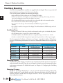
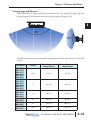
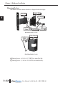
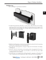
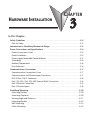
HARDWARE INSTALLATION
CHAPTER
3
2
In This Chapter...
Safety Guidelines . . . . . . . . . . . . . . . . . . . . . . . . . . . . . . . . . . . . . . . . . . . . . . . . . . .3–2
Plan for Safety . . . . . . . . . . . . . . . . . . . . . . . . . . . . . . . . . . . . . . . . . . . . . . . . . . . . .3–2
Introduction to ViewMarq Mechanical Design . . . . . . . . . . . . . . . . . . . . . . . . . . . .3–3
Power Connections and Specifications . . . . . . . . . . . . . . . . . . . . . . . . . . . . . . . . . .3–4
Power Connections Cover . . . . . . . . . . . . . . . . . . . . . . . . . . . . . . . . . . . . . . . . . . . .3–4
Power Installation . . . . . . . . . . . . . . . . . . . . . . . . . . . . . . . . . . . . . . . . . . . . . . . . . .3–4
Power Supply Removable Terminal Blocks . . . . . . . . . . . . . . . . . . . . . . . . . . . . . . . .3–5
Grounding . . . . . . . . . . . . . . . . . . . . . . . . . . . . . . . . . . . . . . . . . . . . . . . . . . . . . . . .3–6
Ambient Temperature . . . . . . . . . . . . . . . . . . . . . . . . . . . . . . . . . . . . . . . . . . . . . . .3–6
Fuse Protection . . . . . . . . . . . . . . . . . . . . . . . . . . . . . . . . . . . . . . . . . . . . . . . . . . . .3–6
Communications Connections . . . . . . . . . . . . . . . . . . . . . . . . . . . . . . . . . . . . . . . . .3–7
Communication Connections Cover . . . . . . . . . . . . . . . . . . . . . . . . . . . . . . . . . . . .3–7
Communication and Discrete Input Connectors . . . . . . . . . . . . . . . . . . . . . . . . . . . .3–7
RS-232 Port 1 RJ12 Connector . . . . . . . . . . . . . . . . . . . . . . . . . . . . . . . . . . . . . . . . .3–8
Port 1 RS-232 / Port 2 RS-485 Terminal Block Connection . . . . . . . . . . . . . . . . . . . .3–8
Port 3 Ethernet Connection . . . . . . . . . . . . . . . . . . . . . . . . . . . . . . . . . . . . . . . . . . .3–9
Port 4 Discrete Inputs . . . . . . . . . . . . . . . . . . . . . . . . . . . . . . . . . . . . . . . . . . . . . . .3–9
ViewMarq Mounting . . . . . . . . . . . . . . . . . . . . . . . . . . . . . . . . . . . . . . . . . . . . . . . .3–10
Mounting Position . . . . . . . . . . . . . . . . . . . . . . . . . . . . . . . . . . . . . . . . . . . . . . . . .3–10
Mounting Clearance . . . . . . . . . . . . . . . . . . . . . . . . . . . . . . . . . . . . . . . . . . . . . . .3–10
Viewing Angle and Distances . . . . . . . . . . . . . . . . . . . . . . . . . . . . . . . . . . . . . . . . .3–11
Mounting Brackets . . . . . . . . . . . . . . . . . . . . . . . . . . . . . . . . . . . . . . . . . . . . . . . . .3–12
Wall Mounting . . . . . . . . . . . . . . . . . . . . . . . . . . . . . . . . . . . . . . . . . . . . . . . . . . . .3–13
Chain Mounting . . . . . . . . . . . . . . . . . . . . . . . . . . . . . . . . . . . . . . . . . . . . . . . . . .3–15
Chapter 3: Hardware Installation
1
2
3
4
5
6
7
8
9
10
11
12
13
14
A
B
C
D
Safety Guidelines
NOTE: Products with CE marks perform their required functions safely and adhere to relevant standards as
specified by CE directives, provided they are used according to their intended purpose and that the instructions in this manual are followed. The protection provided by the equipment may be impaired if this equipment is used in a manner not specified in this manual. A listing of our international affiliates is available on
our web site at http://www.automationdirect.com.
Warning: Providing a safe operating environment for personnel and equipment is your responsibility and
should be your primary goal during system planning and installation. Automation systems can fail and
may result in situations that can cause serious injury to personnel or damage to equipment. Do not rely
on the automation system alone to provide a safe operating environment. You should use external
electromechanical devices, such as relays or limit switches, that are independent of the PLC application
to provide protection for any part of the system that may cause personal injury or damage. Every automation application is different, so there may be special requirements for your particular application.
Make sure you follow all national, state, and local government requirements for the proper installation
and use of your equipment.
Plan for Safety
The best way to provide a safe operating environment is to make personnel and equipment
safety part of the planning process. You should examine every aspect of the system to determine
which areas are critical to operator or machine safety. If you are not familiar with PLC system
installation practices, or your company does not have established installation guidelines, you
should obtain additional information from the following sources.
• NEMA — The National Electrical Manufacturers Association, located in Washington, D.C.,
publishes many different documents that discuss standards for industrial control systems. You can
order these publications directly from NEMA. Some of these include:
ICS 1, General Standards for Industrial Control and Systems
ICS 3, Industrial Systems
ICS 6, Enclosures for Industrial Control Systems
• NEC — The National Electrical Code provides regulations concerning the installation and use of
various types of electrical equipment. Copies of the NEC Handbook can often be obtained from
your local electrical equipment distributor or your local library.
• Local and State Agencies — many local governments and state governments have additional
requirements above and beyond those described in the NEC Handbook. Check with your local
Electrical Inspector or Fire Marshall office for information.
3–2
User Manual, 1st Ed. Rev. B – MD-USER-M
Chapter 3: Hardware Installation
Introduction to ViewMarq Mechanical Design
All ViewMarq displays are similar in appearance. They differ only in size and aspect ratio. The
mounting brackets are identical as are the back covers and all of the power and communication
connections.
The diagram below will allow you to familiarize yourself with the two main compartments,
power and communications.
Communication
Connection
Opening
Communication
Connection
Cover
Power Connection
Opening
Power Connection
Cover
3/4” Cable Gland
1/2” Cable Glands
User Manual, 1st Ed. Rev. B – MD-USER-M
3–3
1
2
3
4
5
6
7
8
9
10
11
12
13
14
A
B
C
D
Chapter 3: Hardware Installation
1
2
3
4
5
6
7
8
9
10
11
12
13
14
A
B
C
D
Power Connections and Specifications
Power Connections Cover
The power connections cover has a 0.83 in (21.1 mm) diameter opening for the supplied 1/2”
NPT water tight cable gland or customer supplied flexible conduit connection for the power
cable. The power connections cover must be installed for all applications. Cover screws should
be torqued to 10 in·lbs (1.1 N·m).
NOTE: The supplied cable glands cannot be used for UL installations. Flexible Conduit to protect cables is
required to maintain UL508 rating.
Power Installation
The ViewMarq message display can be powered by 100-240 VAC or by a user supplied external
24 VDC power supply.
Warning: Do not connect both AC and DC power at the same time. Internal circuit protection will prevent
damage to the message display, but this is an invalid configuration and is not UL compliant.
3–4
User Manual, 1st Ed. Rev. B – MD-USER-M
Chapter 3: Hardware Installation
Power Supply Removable Terminal Blocks
There is a removable 2-pin 24 VDC and a removable 3-pin 120 VAC power connection
terminal block supplied with each ViewMarq message display. Replacement terminal blocks,
Part No. MD-TERM-SET, are available at AutomationDirect.com.
Power Supply Removable Terminal Blocks
Part Number
Terminal
Connector
AC Power
Removable 3-pin terminal block
DC Power
Removable 2-pin terminal block
MD-TERM-SET
Wire Size
Screw Torque
12-14 AWG
solid or stranded
4.5 in·lbs
(0.5 N·m)
Ground
24 VDC
0 VDC
Neutral
100–240 VAC
Ground
N 11
Gr eutr 0–24
ou al
0V
nd
AC
AC Power Input
DC Power Input
Model
Max Input Power
Model
MD4-0112T
22W
MD4-0112T
1A
MD4-0124T
1.5 A
MD4-0212T
2A
MD4-0124T
MD4-0212T
MD4-0224T
MD4-0412T
MD4-0424T
38W
74W
123W
MD4-0224T
MD4-0412T
MD4-0424T
Max DC Current
3.5A
4A
User Manual, 1st Ed. Rev. B – MD-USER-M
3–5
1
2
3
4
5
6
7
8
9
10
11
12
13
14
A
B
C
D
Chapter 3: Hardware Installation
Grounding
1
2
3
4
5
6
7
8
9
10
11
12
13
14
A
B
C
D
The ground terminal on the ViewMarq must be connected to a single point ground. Use
copper stranded wire to achieve low impedance.
A good common ground reference (Earth ground) is essential for proper operation of the
ViewMarq. One side of all control and power circuits and the ground lead on flexible shielded
cable must be properly connected to Earth ground. There are several methods of providing an
adequate common ground reference, including:
a) Installing a ground rod as close to the panel as possible
b) Connection to incoming power system ground
Ambient Temperature
Evaluate any installations where the ambient temperature may approach the lower or upper
limits of the specifications.
3–6
User Manual, 1st Ed. Rev. B – MD-USER-M
Chapter 3: Hardware Installation
Communications Connections
Communication Connections Cover
The communication connections cover has a 0.83 in (21.1 mm) diameter and a 1.06 in (26.9
mm) diameter opening for the supplied 1/2” NPT and 3/4” NPT water tight cable glands or
customer supplied flexible conduit connections for communications. The communication
connections cover must be installed for all applications. Cover screws should be torqued to 10
in·lbs (1.1 N·m).
NOTE: The supplied cable glands cannot be used for UL installations. Flexible Conduit to protect cables is
required to maintain UL508 rating.
Communication Connectors
The following table describes the communication connections available in the ViewMarq
display.
Communications and Discrete Input Connections
Port
Type
Connector
RJ12
Removable 6-pin
terminal block
RJ45
Removable 10-pin
terminal block
Port 1
RS-232
Port 1 / Port 2
RS-232 / RS-485
Port 3
Ethernet
Port 4
Discrete Inputs
Wire Size
Screw Torque
n/a
14-28 AWG
1.7 in·lbs (0.2 N·m)
n/a
14-28 AWG
1.7 in·lbs (0.2 N·m)
RS-232 (Port 1)/
RS-485 (Port 2)
Terminal Block
In 1
In 2
In 3
In 4
CA
In 5
In 6
In 7
In 8
CB
1
2
3
4
5
6
7
8
9
10
Port 2
RS485
5
Port 1
RS232
2
+
SG
TX
RX
RTS
RTS
RJ12
12
rt1
Port1
RS23
232
RS232
RJ45
Ethernet
Et
et
Discrete Inputs
Terminal Block
RS-232 (Port 1)
RJ12 Connector
Ethernet (Port 3)
RJ45 Connector
User Manual, 1st Ed. Rev. B – MD-USER-M
3–7
1
2
3
4
5
6
7
8
9
10
11
12
13
14
A
B
C
D
Chapter 3: Hardware Installation
RS-232 Port 1 RJ12 Connector
1
2
3
4
5
6
7
8
9
10
11
12
13
14
A
B
C
D
Port1 - RS-232 RJ12 Connector
Female RJ12
Pin Number
1
2
3
4
5
6
1234 5 6
Signal Name
Signal GND
Not Used
RXD
TXD
Not Used
Signal GND
Port 1 RJ12
(RS-232)
123456
Port 1 RS-232 / Port 2 RS-485 Terminal Block Connection
Port 1 RS-232 /
Port 2 RS-485
RS-485 + (1)
In 1
1
RS-485
-Port
(2)2 +
In 2
2
RS485
Ground
(3)
InSignal
3
3
SG
In 4 RS-232
4 TX (4)
TX
Port
2
CA RS-232
5 RX (5)
RX
RS232
6
RTS
In 5RS-232
7 RTS (6)
In 6
RJ12
8
In 7
Port1
9
In 8
RS232
10
CB
RJ45
Ethernet
3–8
6 Position Terminal Signal Name
Block Pin Number
1
RS-485 +
2
RS-485 -
3
Signal Ground
4
RS-232 TX
5
RS-232 RX
6
RS-232 RTS
User Manual, 1st Ed. Rev. B – MD-USER-M
Chapter 3: Hardware Installation
Port 3 Ethernet Connection
Port 3 RJ45
(Ethernet)
RJ45 Ethernet Connec- Signal Name
tor Pin Number
87654321
1
TD+
2
TD-
3
RD+
4
No Connection
5
No Connection
6
RD-
7
No Connection
8
No Connection
Port 4 Discrete Inputs
10 Position Terminal Signal Name
Block Pin Number
Discrete Input
In 1
In 2
In 3
In 4
CA
In 5
In 6
In 7
In 8
CB
1
2
3
4
5
6
7
8
9
10
(1) Input 1
(2) Input 2
(3) Input 3
(4) Input 4
(5) Common A
(6) Input 5
(7) Input 6
(8) Input 7
(9) Input 8
(10) Common B
Port 2 +
RS485 SG
TX
Port 2
RX
RS232
RTS
RJ12
Port1
RS232
RJ45
Ethernet
Sourcing Input Wiring
Input 2
Input 4
Input 3
-
Input 4
Common A
Common A
Input 5
Input 5
Input 6
Input 6
Input 8
Common B
Input 7
-
Input 7
+
+
Input 1
Input 2
Input 3
Input 1
2
Input 2
3
Input 3
4
Input 4
5
Common A
6
Input 5
7
Input 6
8
Input 7
9
Input 8
10
Common B
Sinking Input Wiring
Input 1
+
+
1
Input 8
Common B
NOTE: In order to maintain UL508 rating, discrete inputs must be powered from a Class 2 power supply.
User Manual, 1st Ed. Rev. B – MD-USER-M
3–9
1
2
3
4
5
6
7
8
9
10
11
12
13
14
A
B
C
D
Chapter 3: Hardware Installation
1
2
3
4
5
6
7
8
9
10
11
12
13
14
A
B
C
D
ViewMarq Mounting
Two sets of mounting bracket assemblies are supplied with each display. There is one pair of wall
mounting brackets and one pair of chain mount brackets.
These are the general guidelines for mounting the display:
• Only qualified personnel should mount the ViewMarq LED display.
• Verify correct operation of the display on a test bench before mounting. After testing, disconnect
power and communications until after the display is mounted.
• The ViewMarq LED Display is rated for indoor use only and should not be mounted outdoors.
• Protect the lens from scratches while installing the display.
• Do not remove the end caps. This will invalidate the NEMA ratings and void the
warranty.
• Do not drill or cut holes in any part of the display. This will invalidate the NEMA ratings and void
the warranty.
Installation Notes
• In order to maintain UL508 rating, flexible conduit must be used in place of included cable glands.
• The UL508 rating does not apply for a chain mounted display.
• In UL508 installations the allowable ambient air temperature range is 0 - 60 °C (32 - 140 °F)
• In order to maintain UL508 rating, discrete inputs must be powered from a Class 2 power supply.
Use the appropriate hardware and fasteners to hang or suspend the display. All hardware,
fasteners and mounting methods must be rated for a minumum of Four times the weight of the
display.
ViewMarq LED Display Weights
Part Numbers
MD4-0112T
MD4-0124T
MD4-0212T
MD4-0224T
MD4-0412T
MD4-0424T
Weight with
Wall Mount Brackets
Weight with
Chain Mount Brackets
4.9 lbs (2.2 kg)
6.1 lbs (2.8 kg)
5.4 lbs (2.5 kg)
9.0 lbs (4.1 kg)
10.2 lbs (4.6 kg)
9.6 lbs (4.4 kg)
7.3 lbs (3.3 kg)
8.5 lbs (3.9 kg)
7.8 lbs (3.5 kg)
13.1 lbs (6.0 kg)
14.3 lbs (6.5 kg)
14.7 lbs (6.7 kg)
Weight
12.1 lbs (5.5 kg)
9.5 lbs (4.3 kg)
9.7 lbs (4.4 kg)
22.5 lbs (10.2 kg)
18.5 lbs (8.4 kg)
18.7 lbs (8.5 kg)
Mounting Position
The ViewMarq LED display is intended to be mounted horizontally. It may be mounted in
either horizontal direction. When the unit is flipped, the display text will automatically adjust
to the correct orientation. To disable this feature, see Chapter 6 - Configuring the ViewMarq
LED display.
Mounting Clearance
Mount the ViewMarq LED display so as not to exceed the minimum bending radius of the
flexible conduit and / or cable glandss and cables. Mounting the display with the included wall
mounting brackets should allow for adequate clearance. Be sure to provide ample clearance
when using chain mounts.
3–10
User Manual, 1st Ed. Rev. B – MD-USER-M
Chapter 3: Hardware Installation
Viewing Angle and Distances
The ViewMarq LED display should be mounted based on the expected viewing angle and
viewing distance. The horizontal and vertical viewing angle of all signs is 140°.
140°
140°
The table below shows the recommended viewing distances based on the character size that will
be used.
Part Numbers
MD4-0112T
MD4-0124T
MD4-0212T
MD4-0224T
MD4-0412T
MD4-0424T
MD4-0112T
MD4-0124T
MD4-0212T
MD4-0224T
MD4-0412T
MD4-0424T
MD4-0212T
MD4-0224T
MD4-0412T
MD4-0424T
MD4-0412T
MD4-0424T
MD4-0412T
MD4-0424T
MD4-0412T
MD4-0424T
Font Size
Minimum Recommended
Viewing Distance
Maximum Recommended
Viewing Distance
1-1/4 in
6 ft (1.8m)
60 ft (18m)
2 in
10 ft (3.0m)
100 ft (31m)
4 in
20 ft (6.1m)
200 ft (61m)
6 in
20 ft (6.1m)
300 ft (91m)
8 in
20 ft (6.1m)
400 ft (122m)
10 in
20 ft (6.1m)
500 ft (152m)
User Manual, 1st Ed. Rev. B – MD-USER-M
3–11
1
2
3
4
5
6
7
8
9
10
11
12
13
14
A
B
C
D
Chapter 3: Hardware Installation
Mounting Brackets
Wall mount and chain mount brackets are shipped with each display.
1
2
3
4
5
6
7
8
9
10
11
12
13
14
A
B
C
D
Display Side
Wall Side
Flat Washer
Locking
Screws 1
Lock Washer
Pivot
Screw 2
Wall Mount Bracket - 2 each
Locking
Screws 1
Chain Bracket
Chain Mount Bracket - 2 each
1
2
3–12
Locking Screws - (#10-32 x 1/2” SHCS) for 4mm Hex Key.
Locking Screws - (5/16-18 x 5/8” SHCS) for 6mm Hex Key.
User Manual, 1st Ed. Rev. B – MD-USER-M
Chapter 3: Hardware Installation
Wall Mounting
This is an example of a wall mounted installation.
1) Assemble both adjustable wall brackets as shown above. Slide a bracket into the display
mounting rail that runs the length of the back of the display. Repeat for the opposite end.
Place each bracket in the desired position and finger-tighten the two locking screws in each
bracket to prevent them from sliding.
2) Hold the ViewMarq display in the desired mounting position and mark where the mounting
bracket holes are positioned on the mounting surface.
3) Disassemble the mounting brackets, leaving the “display side” of the brackets in the display
mounting rail.
4) Attach the “wall side” of the brackets to the mounting surface using appropriate fasteners for
the type of mounting surface. Make sure the brackets are level with each other. (Wall
mounting hardware is not included.)
5) Install the power and communication cabling through the appropriate cable glands and
covers. Connect power and communication cables to their ports on the message display.
User Manual, 1st Ed. Rev. B – MD-USER-M
3–13
1
2
3
4
5
6
7
8
9
10
11
12
13
14
A
B
C
D
Chapter 3: Hardware Installation
6) Install the covers and make sure that there is enough cable inside the housing to provide a
“service loop” so as not to exceed the minimum bend radius of the cable
1
2
3
4
5
6
7
8
9
10
11
12
13
14
A
B
C
D
Service Loop
7) Install covers being careful to observe the orientation keying. Tighten the captive cover screws
to 10 in·lbs (1.1 N·m). Properly tighten the cable glands to maintain the NEMA rating on
the enclosure.
8) Loosen the “display side” brackets to allow movement in the display mounting rail. Align one
“display side” bracket on the display with the corresponding “wall side” bracket on the wall
and finger tighten the pivot screw with the flat washer and lock washer.
9) While holding the display in position slide the other “display side” bracket in the mounting
rail on the display to line up with the other “wall side” bracket and insert the 6mm pivot
screw with the flat washer and lock washer as shown.
10) Set the desired viewing angle and tighten the pivot screws to 6 in·lbs (0.7 N·m) of torque.
Tighten the locking screws to 9 in·lbs (1.0 N·m) of torque.
3–14
User Manual, 1st Ed. Rev. B – MD-USER-M
Chapter 3: Hardware Installation
Chain Mounting
This is an example of a chain mounted installation.
1) Slide the chain mount brackets into the display mounting rail on each end of the display.
Tighten the locking screws to 9 in-lbs (1.0 N-m).
2) Attach a chain to an appropriate mounting surface or structure at the width listed in the table
below. Connect the chain ends to one of the chain mounting holes on each bracket to
achieve the desired viewing angle.
3) Install the appropriate cabling per steps 5 – 7 in the wall mounting procedure on the previous
pages.
Continued on Next Page.
User Manual, 1st Ed. Rev. B – MD-USER-M
3–15
1
2
3
4
5
6
7
8
9
10
11
12
13
14
A
B
C
D
Chapter 3: Hardware Installation
W
1
2
3
4
5
6
7
8
9
10
11
12
13
14
A
B
C
D
ViewMarq Chain Mount Width
Part Number
MD4-0112T
MD4-0124T
MD4-0212T
MD4-0224T
MD4-0412T
MD4-0424T
3–16
Overall Width with Chain Mount Brackets (W)
23.60 in [599.4 mm]
45.21 in [1148.3 mm]
23.60 in [599.4 mm]
45.21 in [1148.3 mm]
23.60 in [599.4 mm]
45.21 in [1148.3 mm]
User Manual, 1st Ed. Rev. B – MD-USER-M