1
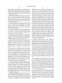
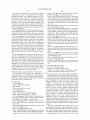
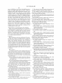
US007010416B2
(12) United States Patent
(10) Patent N0.:
(45) Date of Patent:
Lewis
(54)
SYSTEMS AND METHODS FOR RESETTING
VEHICLE EMISSION SYSTEM ERROR
INDICATORS
U.S. PATENT DOCUMENTS
5,131,372 A *
(*)
Notice:
Subject to any disclaimer, the term of this
patent is extended or adjusted under 35
U.S.C. 154(b) by 0 days.
7/1992
Nakaniwa ................. .. 123/673
5,373,822 A *
5,671,141 A *
12/1994 Thompson ..
9/1997 Smith et al. .
. 123/520
.. 701/29
6,553,754 B1 *
6,615,577 B1 *
4/2003 Meyer et al.
9/2003 Meyer et al.
.. 60/277
.. 60/276
6,691,020 B1 *
2003/0004634 A1 *
2/2004 Meyer et al.
1/2003 Meyer et al.
701/108
701/108
2003/0200025 A1 *
10/2003
Ross ........................ .. 701/200
2003/0217025 A1 *
11/2003
Costantino ................... .. 707/1
2005/0188218 A1 *
(21) Appl. No.: 10/762,190
Mar. 7, 2006
References Cited
(56)
(75) Inventor: Marshall J. Lewis, Lilburn, GA (US)
(73) Assignee: PH2 Solutions, Inc., West Orange, NJ
(Us)
US 7,010,416 B2
8/2005 Walmsley et al. ........ .. 713/200
* cited by examiner
Primary Examiner—John T. KWon
(22)
Filed:
(74) Attorney, Agent, or Firm—IP Counsel Consultants;
Jan. 20, 2004
Michael E. Melton
Prior Publication Data
(65)
US 2004/0215386 A1
(57)
Oct. 28, 2004
A method of resetting an active emissions system error
indictor associated With a vehicle. The method comprises
Related US. Application Data
(60)
(51)
ABSTRACT
Provisional application No. 60/440,910, ?led on Jan.
performing a ?rst requesting step and a second requesting
17, 2003.
step until the active emissions system error indicator resets
in response to the ?rst or second requesting steps. In one
embodiment, the ?rst requesting step comprises requesting
Int. Cl.
B60T 7/12
a ?rst type of information (e.g., information from a ?rst
(2006.01)
vehicle oxygen sensor) from a vehicle computer associated
(52)
U.S. Cl. .................... ..
701/109; 701/114; 324/327;
123/691
(58)
Field of Classi?cation Search .............. ..
701/109,
701/114; 123/691, 692; 324/327, 379, 380;
60/276
See application ?le for complete search history.
With the vehicle, and the second requesting step comprises
requesting a second type of information (e.g., information
from a second vehicle oxygen sensor) from the vehicle
computer. In a particular embodiment of the invention, an
electronic tool, such as a bi-directional scan tool, is used to
perform the ?rst and second requesting steps.
57 Claims, 2 Drawing Sheets
From Step 160
Method of Resetting
Sequentiaiiy execute, In the manner described above, each
of the nine 02 sensor tests regardless of whetherthe tests
are supported by the vehicle. This test sequence is
Emissions-Related
Monitors
preferably done in an evenly-paced manner with no more
than 10430 seoonds between eadi test.
Return to the Function List and enter the "Non-continuous
170
150
tests" screen.
‘
Check for DTC oodes and record.
t
l
Sequentialiy execute, in the manner described above, each
of the displayed "nowcontinuous' tests. regardless of
Check for ‘pending’ codes and record.
paoed manner with no more than 10-30 seoonds between
sequence is preferably done in a substantially evenly
each test.
1
‘
1.
Check and record freeze trame data and reoord Dominant
After one or more 0! the system error indicators has reset,
increase the speed of the vehicle to 55 - 65 mph and drive
t
the vehicle within this range of speeds for tive to ten
minutes. This will help reset the EGR. EVAP and Catalyst
monitors, it necessary.
Erase DTC date.
l,
Continue to repeatedly conduct the O2 sensor tests and
1
"O2 sensor tests" screen.
i
To Step 170
200
210
Non-Continuous tests as described above while the vehicle
Pertorm normal driving in stop and go traftic reaching 20
45 MPH range. This will begin the evaluation of the O2
and 02 Heater Monitors.
Obtain response from the vehicle's POM by entering the
190
whether the nests are supported by the vehicle. This test
is being driven within the 55-65 mph range.
16B
After each 02 sensor test and Non-continuous test has
been executed at least once. enter the ‘Erase Old Data"
220
screen.
i
Follow the directions displayed on the screen tor erasing
the old data.
1
Return to the Function List and determine whether the T
required number of monitors have reset.
230
240
U.S. Patent
Mar. 7, 2006
Sheet 1 0f 2
Method of Resetting
US 7,010,416 B2
100
Emissions-Related
Monitors
/ 1 10
Check for DTC codes and record.
l
/ 120
Check for "pending" codes and record.
1
Check and record freeze frame data and record Dominant’
Code.
i
/130
,/ 140
Erase DTC data.
V
Perform normal driving in stop and go traffic reaching 20- / /150
45 MPH range. This will begin the evaluation of the O2
and 02 Heater Monitors.
l
Obtain response from the vehicle's PCM by entering the
"O2 sensor tests" screen.
i
To Step 170
FIG. 1A
,/ 160
U.S. Patent
Mar. 7, 2006
Sheet 2 0f 2
US 7,010,416 B2
From Step 160
l
sequentially execute, in the manner described above, each / 170
of the nine 02 sensor tests regardless of whether the tests’
are supported by the vehicle. This test sequence is
preferably done in an evenly-paced manner with no more
than 10-30 seconds between each test.
Return to the Function List and enterthe "Non-continuous ,/ 180
tests" screen.
i
Sequentially execute, in the manner described above, each / 190
of the displayed "non-continuous" tests, regardless of ”
whether the tests are supported by the vehicle. This test
sequence is preferably done in a substantially evenly
paced manner with no more than 10-30 seconds between
each test.
// 200
After one or more of the system error indicators has reset,
increase the speed of the vehicle to 55 - 65 mph and drive
the vehicle within this range of speeds for five to ten
minutes. This will help reset the EGR, EVAP and Catalyst
monitors, if necessary.
1
Continue to repeatedly conduct the O2 sensor tests and ’
Non-Continuous tests as described above while the vehicle
/210
is being driven within the 55-65 mph range.
V
After each 02 sensor test and Non-continuous test has // 220
been executed at least once, enter the "Erase Old Data"
screen.
1
Follow the directions displayed on the screen for erasing /
/ 230
the old data.
Return to the Function List and determine whether the
l/ 240
required number of monitors have reset.
FIG. 1B
US 7,010,416 B2
1
2
When putting the vehicle through the drive cycle, the
SYSTEMS AND METHODS FOR RESETTING
VEHICLE EMISSION SYSTEM ERROR
INDICATORS
technician also activates various vehicle systems, such as the
vehicle’s air conditioning system. If all of the vehicle’s
systems are functioning properly, and if the drive cycle is
eXecuted properly by the technician, all of the vehicle’s
CROSS-REFERENCE TO RELATED
APPLICATIONS
active system error indicators Will reset automatically in
response to the vehicle being put through the drive cycle.
Technicians typically attach a scan tool to the vehicle While
This application claims the bene?t of US. provisional
performing the drive cycle to manually verify, in real time,
patent application 60/440,910 entitled “Systems and Meth
ods for Resetting Automobile Emission System Error Indi
10
that the vehicle’s system error indicators are resetting prop
cators”, Which Was ?led on Jan. 17, 2003, and Which is
erly.
hereby incorporated herein by reference in its entirety.
Once the technician determines that all of the vehicle’s
system error indicators have reset properly, the vehicle’s
oWner takes the vehicle back to an emissions testing facility
BACKGROUND OF THE INVENTION
15
system error indicators are “active” (e.g., that the current
cially in particularly congested areas, such as large cities.
Accordingly, modern vehicles are equipped With sophisti
cated emissions systems that are con?gured to reduce harm
ful emissions from the vehicle. These vehicles are also
20
equipped With a variety of sophisticated emissions-related
devices for informing the vehicle’s oWner and vehicle
technicians if the vehicle’s emissions systems are not func
tioning properly.
Where an emissions tester veri?es that the vehicle’s check
engine light is not illuminated, and that none of the vehicle’s
It has become apparent that gas emissions from vehicles
(such as automobiles) can contribute to air pollution, espe
status of all the vehicle’s readiness monitors is “ready”).
Once this veri?cation process is complete, the vehicle is
certi?ed as having passed the emissions test.
One problem With the current emissions testing process is
that the prior art process of resetting active system error
indicators is unnecessarily time-consuming. This is due to
the fact that standard drive cycles typically require that the
25
vehicle be driven for at least 40 minutes to properly com
plete the drive cycle. In fact, it commonly takes an hour or
One such emissions-related device is a “check engine”
more to properly reset a vehicle’s system error indicators
light (or malfunction indicator light), Which is commonly
located on the vehicle’s dashboard. Such “check engine”
using prior art techniques.
lights are typically con?gured to illuminate When the vehi
cle’s on-board computer detects a problem With the vehi
Another problem With current emissions testing processes
is that the prior art process of resetting active system error
indicators is often dif?cult and unsafe. This is due to the fact
that standard drive cycles often require that the vehicle be
cle’s emissions system.
The vehicle is also equipped With a variety of emissions
related sensors that are con?gured to monitor (either con
tinuously or intermittently) various aspects of the vehicle’s
35
emissions system. These sensors are con?gured to transmit
data to a computer Within the vehicle for analysis by the
computer. If the computer determines that data from one or
more of the sensors is indicative of a problem Within the
vehicle’s emissions system, the computer activates one or
more system error indicators (Which are commonly referred
40
to as readiness monitor points or “?ags”). These system
error indicators are then used to help technicians diagnose
driven in a rigorously prescribed manner in order to reset the
various system error indicators. For eXample, the Ford drive
cycle referenced above requires that a driver drive the
vehicle continuously for 10 minutes at a speeds of 45—65
mph While avoiding sharp turns and hills. This can be
dif?cult and unsafe to achieve in certain settings, especially
on the congested roadWays common to most major cities.
Accordingly, there is a need for an improved method and
apparatus for resetting active emissions system error indi
cators that may be performed quickly and safely.
and repair the vehicle’s emissions system. In addition, the
system error indicators may be used by state-certi?ed emis
sions testing authorities to determine Whether the vehicle
45
meets state emissions standards.
In many states, such as Georgia, in order for a vehicle to
SUMMARY OF THE INVENTION
Various embodiments of the present invention provide
improved methods and apparatuses for quickly and safely
pass a regularly scheduled emissions test, the vehicle’s
“check engine” light must be off, and the vehicle must not
vehicle’s OBD II readiness monitors must not indicate that
there is a problem With the vehicle’s emissions-related
resetting active emissions system error indicators Within a
vehicle (such as an automobile). One embodiment of the
invention is a method of resetting active emissions system
error indicators by requesting tWo or more different types of
information from the vehicle’s computer. In one embodi
systems or components). If a vehicle fails inspection, the
ment of the invention, the method comprises requesting, in
have any currently active system error indictors (e.g., the
oWner typically takes the vehicle to a mechanic Who uses a 55 a pre-determined sequence, tWo or more different types of
diagnostic tool, such as a “scan tool”, to determine Which of
the vehicle’s system error indicators are currently active.
The mechanic then uses this information to determine
Which, if any, speci?c repairs are needed to bring the vehicle
into compliance With emissions standards.
information from the vehicle’s computer. In a further
embodiment of the invention, a tool (preferably an elec
tronic tool, such as a scan tool, and preferably a bi-direc
tional scan tool) is used to request the tWo or more different
60
Once the repairs are done, it is necessary to deactivate or
“reset” any active system error indicators. To do this, a
sional Enhanced Scan Tool (Model Number MD2001A),
Which is currently manufactured by Actron Manufacturing
technician typically puts the vehicle through a “drive cycle”,
such as the Ford P1000, I/M Readiness Code Drive Cycle.
As Will be understood by one skilled in the art, during the
“drive cycle”, the vehicle is operated in various prescribed
Ways for speci?ed periods of time.
types of information from the vehicle’s computer. In one
embodiment of the invention, the scan tool is the Profes
65
Company of Cleveland Ohio. The current user manual for
this scan tool Was included in AppendiX B of the provisional
patent application referenced above, Which is incorporated
herein by reference.
US 7,010,416 B2
4
3
In one embodiment of the invention, each of the tWo or
In one embodiment of the invention, the step of requesting
more different types of information requested from the
vehicle’s computer includes emissions-related information.
This information is preferably information that has been
computer comprises a ?rst step of requesting a ?rst set of
tWo or more different types of information from the vehicle
information (e.g., the results of an oxygen sensor test or a
acquired from one or more sensors Within the vehicle, each
of Which is preferably adjacent to or Within the vehicle’s
engine. A particular embodiment of the invention is a
method of resetting active emissions system error indicators
by requesting, in sequence, tWo or more different types of
information from a vehicle’s poWer train control module
10
(PCM). This is preferably done electronically using a scan
tool, such as the Professional Enhanced Scan Tool refer
enced above.
In one embodiment of the invention, the method of
non-continuous test) from the vehicle computer, and a
second step of requesting a second set of information from
the vehicle computer after receiving the ?rst set of infor
mation from the vehicle computer. The second step of
requesting a second set of information is preferably per
formed about 60 seconds or less after receiving the ?rst set
of information. In a further embodiment of the invention, the
step of requesting tWo or more different types of information
comprises a third step of requesting a third set of information
from the vehicle computer. This step is preferably performed
resetting one or more active emission system error indicators 15 about 60 seconds or less after receiving the second set of
comprises requesting, in sequence, three, four, ?ve, six,
mation from a ?rst oxygen sensor Within the vehicle. The
information.
In a preferred embodiment of the invention, the second
step of requesting a second set of information is performed
about 30 seconds or less (and preferably 20 seconds or less)
after receiving the ?rst set of information. Also, the third
step of requesting a third set of information from the vehicle
computer is preferably performed about 30 seconds or less
inventive method preferably also comprises the step of
(and preferably 20 seconds or less) after receiving the
seven, eight or more different types of information from a
vehicle computer.
In a particular embodiment of the invention, the step of
requesting tWo or more different types of information from
the vehicle computer comprises the step of requesting infor
second set of information.
the vehicle. One embodiment of the inventive method also 25
As noted above, one embodiment of the invention com
prises the general concept of using a scan tool to reset active
preferably comprises the step of requesting information
emissions system error indicators on a vehicle.
from a third oxygen sensor Within the vehicle. In various
A method of resetting one or more active emission system
embodiments of the invention, the inventive method com
error indicators according to yet another embodiment of the
prises requesting one to nine or more values from different
requesting information from a second oxygen sensor Within
invention comprises the steps of: (1) placing a vehicle on a
oxygen sensors Within the vehicle. Such oxygen sensors
dynamometer; and (2) While the vehicle is on the dynamom
may include, for example: (1) an oxygen sensor that is
adjacent a ?rst cylinder bank and that is upstream of a ?rst
eter, requesting tWo or more different types of information
from a computer Within the vehicle. In a preferred embodi
catalyst associated With the ?rst cylinder bank; (2) an
oxygen sensor that is adjacent the ?rst cylinder bank and that
is doWnstream of the ?rst catalyst associated With the ?rst
cylinder bank; (3) an oxygen sensor that is adjacent a second
cylinder bank and that is upstream of a ?rst catalyst asso
ciated With the second cylinder bank; (4) an oxygen sensor
that is adjacent the second cylinder bank and that is doWn
stream of the ?rst catalyst associated With the second
ment of the invention, this method comprises requesting, in
35 a pre-determined sequence, tWo or more different types of
information from the computer. In a further preferred
embodiment of the invention, a scan tool is used to perform
the step of requesting tWo or more different types of infor
40
cylinder bank. Other such sensors are described on Pages
3—6 of the user manual for the Professional Enhanced Scan
mation from the computer.
As Will be understood by one skilled in the art, While the
inventive concepts described above are referred to as inven
tive methods, the present invention may also be embodied in
systems or devices that are con?gured to perform the
Tool referenced above.
As noted above, the user preferably requests information
methods referenced herein. In addition, the present invention
from the various oxygen sensors using a scan tool, such as 45 may also be embodied in a computer readable medium
the Professional Enhanced Scan Tool referenced above or
storing computer-readable instructions for executing the
other bi-directional scan tool. Such bi-directional scan tools
methods referenced herein. In various embodiments of the
are Well knoWn in the art and include: (1) model KM9640 by
invention, the systems, devices, or computer-readable
instructions are con?gured for executing the various steps of
Actron Manufacturing Company; and (2) the Mastertech
MTS Tech 1A by Vetronix Corporation.
the various methods referenced herein substantially auto
matically (i.e., substantially Without human intervention).
As Will be understood by one skilled in the art, users may
alternatively use any other suitable device to request infor
mation from the vehicle’s various sensors. For example, a
BRIEF DESCRIPTION OF THE DRAWINGS
Visor Personal Digital Assistant equipped With D101 Visor
“OTTOSCAN” softWare may be suitable for this purpose.
In a preferred embodiment of the invention, the step of
requesting tWo or more different types of information from
the vehicle computer comprises performing one or more
“non-continuous tests” on the vehicle’s engine. Such tests
55
are knoWn in the art and are described in greater detail on
pages 3—7 and 3—8 of the Professional Enhanced Scan Tool
User Manual referenced above. In a preferred embodiment
of the invention, at least one of these non-continuous tests
provides test results from a catalyst monitor. In a further
preferred embodiment of the invention, at least one of the
non-continuous tests provides test results from an evapora
tive OBD II monitor.
Having thus described the invention in general terms,
reference Will noW be made to the accompanying draWings,
Wherein:
FIGS. 1A and 1B depict a method of resetting emissions
related monitors according to a particular embodiment of the
invention.
DETAILED DESCRIPTION OF THE
INVENTION
65
The present invention Will noW be described in greater
detail, and in reference to various particular embodiments of
the invention. As Will be understood by one skilled in the
US 7,010,416 B2
5
6
relevant ?eld, the invention may be embodied in many
appropriate button on the scan tool. After this ?rst test is
different forms and should not be construed as limited to the
complete (e.g., the scan tool has displayed results for the ?rst
embodiments set forth beloW. Rather, these embodiments
are provided so that this disclosure Will be thorough and
complete, and Will fully convey the scope of the invention
oxygen sensor test), the user preferably Waits about 20
seconds or less, and then initiates a second oxygen sensor
test (preferably the Lean to Rich sensor threshold voltage
to those skilled in the art.
test). After this second test is complete, the user preferably
It should also be understood that, While certain embodi
ments of the invention comprise inventive methods that
Waits about 20 seconds or less and then initiates a third
oxygen sensor test (preferably the LoW sensor voltage for
include one or more steps, in some circumstances, certain of
these steps may be omitted or executed in different
10
sequences than described herein, and that additional steps
may be added Without taking the method outside the scope
of the present invention.
The methods described herein may be performed While
the vehicle is operating on a paved surface, such as a road,
or on an unpaved surface. Alternatively, the methods
sWitch time test). After this third test is complete, the user
preferably Waits about 20 seconds or less and then initiates
a fourth oxygen sensor test (preferably the High sensor
voltage for sWitch time test). After this fourth test is com
plete, the user preferably Waits about 20 seconds or less and
15
then initiates a ?fth oxygen sensor test (preferably the Rich
to Lean sensor sWitch time test). After this ?fth oxygen
sensor test is complete, the user preferably Waits about 20
described herein may be performed While the vehicle is
seconds or less and then initiates a sixth oxygen sensor test
disposed on a dynamometer (e.g., one or more substantially
(preferably the Lean to Rich sensor threshold voltage test).
After this sixth test is complete, the user preferably Waits
stationary spinning rollers).
In order to use a method according to one embodiment of
the invention to reset one or more active emission system
error indicators, a user ?rst Warms up the vehicle’s engine
about 20 seconds or less and then initiates a seventh oxygen
sensor test (preferably the LoW sensor voltage for sWitch
time test). After this seventh test is complete, the user
preferably Waits about 20 seconds or less and then initiates
an eighth oxygen sensor test (preferably the High sensor
for at least ?ve minutes. In another embodiment of the
invention, the user may omit this step.
The user then connects a diagnostic tool (preferably an
electronic diagnostic tool), to the vehicle in a manner knoWn
in the art. In a preferred embodiment of the invention, the
diagnostic tool is a scan tool, such as the MD 2001A
Professional Enhanced Scan Tool referenced above.
The user then uses the diagnostic tool to retrieve infor
25
voltage for sWitch time test). After this eighth test is com
plete, the user preferably Waits about 20 seconds or less and
then initiates a ninth oxygen sensor test (preferably the Rich
to Lean sensor sWitch time test).
It should be understood that the above sequence of
performing oxygen sensor tests may vary in order and
mation from one or more of the vehicle’s oxygen sensors. As
timing from the sequence and timing pattern set forth above.
described in detail in the user manual for the MD 2001A
Professional Enhanced Scan Tool, to do this, the user
preferably selects an “O2 monitor test” option from the
For example, the user may execute the Lean to Rich sensor
threshold voltage test as the ?rst test rather than the second.
Similarly, the user may execute the “High sensor voltage for
OBD II function list to indicate that the user Would like to 35 sWitch time” test as the second test rather than the fourth.
use the diagnostic tool to initiate one or more oxygen sensor
tests.
By the same token, in one embodiment of the invention,
tWo or more of the above oxygen sensor tests are performed
The user then uses the diagnostic tool to initiate, prefer
simultaneously rather than sequentially. In another embodi
ably in sequence, tWo or more oxygen sensor tests. During
each of these tests, the diagnostic tool retrieves information
40
from at least a particular one of the vehicle’s oxygen
sensors. In various preferred embodiments of the invention,
the user uses the diagnostic tool to initiate at least three, four,
?ve, six, seven, eight, nine, or more oxygen sensor tests. In
a preferred embodiment of the invention, the user uses the
ment of the invention, the user Waits longer than 20 seconds
(e.g., about 50 seconds or less) after a particular oxygen
sensor test is completed to initiate the next sequential
oxygen sensor test. For example, in one embodiment of the
invention, the user ?rst initiates a ?rst oxygen sensor test
45
and, after this ?rst test is complete, the user Waits about 50
seconds or less, and then initiates a second oxygen sensor
diagnostic tool to initiate these tests substantially sequen
tially. When such tests are performed sequentially, the user
test.
uses the diagnostic tool to conduct one test at a time.
In one embodiment of the invention, after the user com
pletes at least tWo of the oxygen sensor tests as described
Alternatively, the user may use the diagnostic tool to per
form tWo or more of the tests simultaneously.
In a preferred embodiment of the invention, the diagnostic
tool is con?gured to perform a plurality of different oxygen
sensor tests. For example, the diagnostic tool is preferably
above (and preferably after all nine of the oxygen sensor
tests have been completed as described above), the user
executes one or more “non-continuous tests”. These tests are
preferably executed in the manner set forth on pages 3—8 of
the user manual for the MD 2001A Professional Enhanced
con?gured to conduct tWo or more of the folloWing oxygen
sensor tests: (1) Rich to Lean sensor threshold voltage; (2) 55 Scan Tool. In one embodiment of the invention, the user
executes a ?rst non-continuous test Within about 60 seconds
Lean to Rich sensor threshold voltage; (3) LoW sensor
voltage for sWitch time; (4) High sensor voltage for sWitch
(and preferably about 20 seconds or less) after completing
time; (5) Rich to Lean sensor sWitch time; (6) Lean to Rich
sensor threshold voltage; (7) LoW sensor voltage for sWitch
the last of the oxygen sensor tests.
time; (8) High sensor voltage for sWitch time; and (9) Rich
to Lean sensor sWitch time.
In a preferred embodiment of the invention, the user uses
the MD 2001A Professional Enhanced Scan Tool referenced
above to perform the step of initiating tWo or more oxygen
In a preferred embodiment of the invention, the user ?rst
sequentially executes each of three or more (and preferably
all nine) oxygen sensor tests as described above, and then
executes one or more “non-continuous tests” Within about
60 seconds (and preferably about 20 seconds or less) after
completing the last of the oxygen sensor tests. Such non
sensor tests. In this embodiment of the invention, the user 65 continuous tests, include, for example, tests for receiving
data from the vehicle’s catalyst and evaporative OBD II
?rst initiates a ?rst oxygen sensor test (preferably the Rich
to Lean sensor threshold voltage test) by selecting an
monitors.
US 7,010,416 B2
8
7
In a preferred embodiment of the invention, the step of
6. Next, at Step 160, obtain a response from the vehicle’s
PCM by entering the “O2 sensor tests” screen.
7. Next, at Step 170, sequentially execute, in the manner
described above, each of the nine 02 sensor tests regard
less of Whether the tests are supported by the vehicle. This
test sequence is preferably done in a substantially evenly
executing one or more “non-continuous tests” comprises
executing (preferably in a sequential manner) tWo, three,
four, ?ve, six, seven, or more non-continuous tests. In one
embodiment of the invention, the various non-continuous
tests are executed no more than about 60 seconds (and
preferably no more than about 20 seconds or less) apart. That
is, there user executes each non-continuous test Within 60
seconds (and preferably no more than about 20 seconds or
less) of receiving the results from any immediately preced
paced manner With no more than 10—30 seconds betWeen
each test.
8. Next, at Step 180, return to the Function List and enter the
10
ing non-continuous test.
After completing the last of the non-continuous tests, the
user preferably repeats the oxygen sensor and non-continu
vehicle or not. This test sequence is preferably done in a
ous tests in the manner set forth above until one or more (and
preferably all) of the vehicle’s system error indicators resets.
“Non-continuous tests” screen.
9. Next, at Step 190, sequentially execute, in the manner
described above, each of the displayed “non-continuous”
tests, regardless of Whether the tests are supported by the
15
In one embodiment of the invention, the user ?rst
executes the oxygen sensor and non-continuous tests repeat
edly While driving the vehicle in stop and go traffic prefer
ably betWeen speeds of 20—45 mph. Next, in response to
determining that one or more of the vehicle’s oxygen sensor
substantially evenly paced manner With no more than
10—30 seconds betWeen each test.
10. Next, at Step 200, after one or more of the system error
indicators has reset, increase the speed of the vehicle to
55—65 mph and drive the vehicle Within this range of
speeds for ?ve to ten minutes. This Will contribute to
system error indicators have reset, the user preferably
resetting the EGR, EVAP and Catalyst monitors, if nec
increases the speed of the vehicle to betWeen 55 and 65 mph
essary.
11. Next, at Step 210, continue to repeatedly run the O2
and then executes the oxygen sensor and non-continuous
tests repeatedly While driving the vehicle in this range of
speeds for ?ve to ten minutes. This helps to activate and
sensor tests and Non-Continuous tests as described above
25
mph.
reset the EGR, EVAP and CATALYST monitors, if neces
sary.
In one embodiment of the invention, after the user com
pletes the various oxygen sensor and non-continuous tests at
least once While driving in the 55—65 mph range, the user
executes an “erase old data” function on the diagnostic tool.
12. Next, at Step 220, after each 02 sensor test and Non
continuous test has been executed at least once, enter the
“Erase Old Data” screen.
13. Next, at Step 230, folloW the directions displayed on the
screen for erasing the old data.
14. Finally, at Step 240, return to the Function List and
determine Whether the required number of monitors have
This removes any old data stored during testing and reveals
the neWest, more recent data. The user then returns to the
diagnostic tool’s “function list” and determines Whether the
required system error indicators have reset. If the system
reset.
35
error indicators have not reset at this time, the user returns
to diagnostic tool’s vieW data screen and uses this screen to
40
A method for resetting system error indicators on a
described in step-by-step format beloW. This method is
on a vehicle’s emissions system (for example, in the manner
set forth above) serves to stimulate the vehicle’s PCM to
preferably performed using the MD 2001A Professional
45
Initial Procedure:
. Connect Scan tool.
. Choose OBD II Global vehicle.
tors (e.g., reset the vehicle’s readiness monitors) in much
less time than prior art methods. For example, prior art
. Erase stored data from scan tool.
Go to function list.
methods for resetting a vehicle’s system error indicators
typically take over 75 minutes, and often several hours, or
days, to complete. In contrast, various embodiments of the
. Select IIM Readiness.
55 invention may be used to reset a vehicle’s system error
After conducting the “Initial Procedure” described above,
the user begins performing the various steps shoWn in FIGS.
indicators in one to 15 minutes, provided there are no
mechanical problems that Would prevent it from doing so. In
addition, various methods disclosed herein may be used to
1A and 1B, Which are listed in sequence beloW.
1. At Step 110, check for DTC codes and record these codes.
quickly and accurately identify Whether the vehicle’s emis
2. Next, at Step 120, check for “pending” codes and record
sion system needs to be repaired and, if so, What repairs are
needed.
As Will be understood by one skilled in the art, it is
currently understood in the automotive ?eld that, in order to
these codes.
3. Next, at Step 130, check and record freeZe frame data and
record the dominant code.
4. Next, at Step 140, erase DTC data.
5. Next, at Step 150, perform normal driving in stop and go
traf?c at speeds reaching the 20-45 MPH range. This Will
begin the evaluation of the O2 and 02 Heater Monitors.
perform diagnostic tests earlier than it Would under normal
driving conditions, or under the driving conditions pre
scribed by a typical drive cycle. Thus, When executed
properly, in one embodiment of the invention, the above
techniques serve to reset the vehicle’s system error indica
. Start vehicle.
. Check for and record Incomplete Monitors.
. AlloW engine to Warm-up for 3—5 minutes.
2. Check and record the displayed values.
3. Compare the recorded values to anticipated “normal”
values and determine if further repairs are needed.
Selected Advantages of the Inventive System and Method
Using a diagnostic tool to rapidly perform diagnostic tests
vehicle according to one embodiment of the invention is
Enhanced Scan Tool referenced above.
If the Monitors Have Not Reset:
1. Go to the “View Data” screen.
determine Whether further repairs are needed.
Method According to One Embodiment of the Invention
While the vehicle is being driven at speeds betWeen 55—65
reset a vehicle’s readiness monitors, it is necessary to drive
65
the vehicle through certain driving patterns under pre
determined operating conditions (such as those included in
an appropriate drive cycle). For example, in the most recent
US 7,010,416 B2
10
Michigan, the author notes “(i)n order to reset the readiness
7. The method of claim 6, Wherein said second type of
information comprises emissions-related information.
8. The method of claim 6, Wherein said ?rst type of
information is information that has been acquired from one
monitors to ‘Ready’, certain driving patterns and operating
or more sensors Within said vehicle.
conditions must be met. Unlike DTCs, Readiness Monitors
cannot be manipulated via a scan tool.” Similarly, the author
states that “The monitored system cannot be checked When
the engine is started brie?y and is shut-doWn, nor can the
status of the monitor be re-set through the scan tool. The
scan tool can verify the status of the monitor, but cannot
9. The method of claim 8, Wherein said second type of
information is information that has been acquired from said
issue of “OBDII Drive Cycle Guide, 1996-2002 Domestic &
Import Cars, Light Trucks, Vans, and SUVs”, Which Was
published in 2002 by MOTOR Information Systems of Troy,
one or more sensors.
10
change the status.” (See page ix). Accordingly, in a manner
contrary to current teachings and practices in the automotive
?eld, the above method alloWs technicians to legally and
?rst oxygen sensor Within said vehicle.
effectively use a scan tool to quickly reset a vehicle’s 15
readiness monitors Without executing a complicated, time
consuming prior art drive cycle.
Automated Device for Performing the Above Methods
While various methods described herein are described as
being performed by a technician using a tool, such as a scan
20
tool, it should be understood that the present invention
said ?rst cylinder bank.
14. The method of claim 11, Wherein said second type of
information is information that has been acquired from a
(e.g., Without human intervention).
Conclusion
Many modi?cations and other embodiments of the inven
second oxygen sensor Within said vehicle.
tion Will come to mind to one skilled in the art to Which this
is not to be limited to the speci?c embodiments disclosed
and that modi?cations and other embodiments are intended
to be included Within the scope of the appended claims.
30
cylinder bank; and
cylinder bank, upstream of a catalyst associated With
said ?rst cylinder bank; and
35
16. The method of claim 14, Wherein:
said method further comprises a third requesting step, said
40
performing a ?rst requesting step and a second requesting
step until said active emissions system error indicator resets
in response to at least one of said ?rst or second requesting 45
steps, and Wherein:
said ?rst requesting step comprises requesting a ?rst type
said vehicle; and
said second requesting step comprises requesting a second
type of information from said vehicle computer.
2. The method of claim 1, Wherein said step of performing
said second oxygen sensor is disposed adjacent said ?rst
cylinder bank, doWnstream of said ?rst catalyst; and
said third oxygen sensor is disposed adjacent said second
55
60
the same time.
4. The method of claim 1, Wherein said ?rst requesting
step is executed electronically.
cylinder bank, upstream of a catalyst associated With
said second cylinder bank.
18. The method of claim 16, Wherein:
said method further comprises a fourth requesting step,
said fourth requesting step comprising the step of
requesting a fourth type of information from said
vehicle computer; and
said fourth type of information is information that has
been acquired from a fourth oxygen sensor Within said
vehicle.
5. The method of claim 4, Wherein said second requesting
6. The method of claim 1, Wherein said ?rst type of
information comprises emissions-related information.
a third type of information from said vehicle computer;
and
said third type of information is information that has been
acquired from a third oxygen sensor Within said
vehicle.
17. The method of claim 16, Wherein:
said vehicle has an engine that comprises both a ?rst
cylinder bank, upstream of a catalyst associated With
said ?rst cylinder bank;
pre-determined sequence.
step is executed electronically.
third requesting step comprising the step of requesting
cylinder bank and a second cylinder bank;
said ?rst oxygen sensor is disposed adjacent said ?rst
of information from a vehicle computer associated With
3. The method of claim 1, Wherein said step of performing
a ?rst requesting step and a second requesting step until said
active emissions system error indicator resets comprises
performing said ?rst and second requesting steps at about
said second oxygen sensor is disposed adjacent said ?rst
cylinder bank, doWnstream of said ?rst catalyst.
in a generic and descriptive sense only and not for purposes
of limitation.
a ?rst requesting step and a second requesting step until said
active emissions system error indicator resets comprises
performing said ?rst and second requesting steps in a
15. The method of claim 14,
said vehicle comprises an engine that comprises a ?rst
said ?rst oxygen sensor is disposed adjacent said ?rst
Although speci?c terms are employed herein, they are used
What I claim is:
1. A method of resetting an active emissions system error
indictor associated With a vehicle, said method comprising
12. The method of claim 11, Wherein:
said vehicle comprises an engine comprising a ?rst cyl
inder bank; and
said ?rst oxygen sensor is disposed adjacent said ?rst
cylinder bank, upstream of a catalyst associated With
said ?rst cylinder bank.
13. The method of claim 11, Wherein:
said vehicle has an engine comprises a ?rst cylinder bank;
and
said ?rst oxygen sensor is disposed adjacent said ?rst
cylinder bank, doWnstream of a catalyst associated With
includes devices (such as electronic devices) that are con
?gured (e.g., programmed) for executing one or more steps
of any of the above methods substantially automatically
invention pertains having the bene?t of the teachings pre
sented in the foregoing descriptions and the associated
drawings. Therefore, it is to be understood that the invention
10. The method of claim 9, Wherein each of said one or
more sensors is adjacent said vehicle’s engine.
11. The method of claim 1, Wherein said ?rst type of
information is information that has been acquired from a
65
19. The method of claim 18, Wherein:
said vehicle comprises an engine comprising both a ?rst
cylinder bank and a second cylinder bank;
US 7,010,416 B2
11
12
said method comprises executing said second requesting
said ?rst oxygen sensor is disposed adjacent said ?rst
cylinder bank, upstream of a ?rst catalyst that is asso
step after receiving said ?rst type of information from
said vehicle computer.
ciated With said ?rst cylinder bank;
said second oxygen sensor is disposed adjacent said ?rst
35. A method of resetting one or more active emission
system error indicators associated With a vehicle, said
cylinder bank, doWnstream of said ?rst catalyst;
method comprising the steps of:
said third oxygen sensor is disposed adjacent said second
cylinder bank, upstream of a second catalyst that is
placing said vehicle on a dynamometer; and
While said vehicle is on said dynamometer, requesting tWo
associated With said second cylinder bank; and
said fourth oxygen sensor is disposed adjacent said sec
ond cylinder bank, doWnstream of said second catalyst.
20. The method of claim 1, Wherein said ?rst requesting
10
step is executed using a scan tool.
21. The method of claim 1, Wherein said scan tool is a
36. The method of claim 35, further comprising request
ing said tWo or more different types of information in a
bidirectional scan tool.
22. The method of claim 20, Wherein said second request
ing step is executed using said scan tool.
15
23. The method of claim 22, Wherein said scan tool is a
tronic device being con?gured for:
on an engine Within said vehicle.
performing a ?rst requesting step and a second requesting
step until said active emissions system error indicator
resets in response to at least one of said ?rst or second
25
27. The method of claim 1, Wherein:
said ?rst requesting step comprises a step of requesting a
?rst set of information from said vehicle computer;
said method comprises receiving said ?rst set of infor
mation from said vehicle computer;
of information from a vehicle computer associated With
type of information from said vehicle computer; and
said electronic device is con?gured for performing said
?rst requesting step and said second requesting step
substantially automatically until said active emissions
a second set of information from said vehicle computer
system error indicator resets.
35
40
31. The method of claim 30, Wherein said second request
ing step is performed about 30 seconds or less after said step
of receiving said ?rst set of information from said vehicle
computer.
32. The method of claim 30, Wherein:
said method further comprises a third requesting step that
comprises requesting a third set of information from
said vehicle computer; and
said third requesting step is performed about 60 seconds
or less after said step of receiving said second set of
information from said vehicle computer.
33. The method of claim 32, Wherein:
said second requesting step is performed about 30 seconds
or less after said step of receiving said ?rst set of
information; and
said third requesting step is performed about 30 seconds
determining Whether said active emissions system error
indicator has reset; and
in response to determining that said active emissions
system error indicator has reset, stopping execution of
said ?rst and second requesting steps.
40. The electronic device of claim 38, Wherein said step
of performing a ?rst requesting step and a second requesting
30. The method of claim 27, Wherein second requesting
step is performed about 60 seconds or less after said step of
receiving said ?rst set of information from said vehicle
computer.
39. The electronic device of claim 38, said electronic
device being con?gured for:
information comprises the results of an oxygen sensor test.
29. The method of claim 27, Wherein said ?rst set of
information comprises the results of a non-continuous test.
requesting steps, and Wherein:
said ?rst requesting step comprises requesting a ?rst type
said vehicle;
said second requesting step comprises requesting a second
said second requesting step comprises a step of requesting
after receiving said ?rst set of information from said
vehicle computer; and
said method comprises receiving said second set of infor
mation from said vehicle computer.
28. The method of claim 27, Wherein said ?rst set of
37. The method of claim 35, Wherein a scan tool is used
to perform said step of requesting tWo or more different
38. An electronic device for resetting an active emissions
system error indictor associated With a vehicle, said elec
24. The method of claim 1, Wherein said ?rst requesting
step comprises performing at least one non-continuous test
test provides test results from an OBD-2 monitor.
predetermined sequence.
types of information from said computer.
bidirectional scan tool.
25. The method of claim 24, Wherein said non-continuous
test provides test results from a catalyst monitor.
26. The method of claim 25, Wherein said non-continuous
or more different types of information from a computer
Within said vehicle until at least one of said active
emission system error indicators resets.
45
step until said active emissions system error indicator resets
comprises performing said ?rst and second requesting steps
in a pre-determined sequence.
41. The electronic device of claim 38, Wherein said step
of performing a ?rst requesting step and a second requesting
step until said active emissions system error indicator resets
comprises performing said ?rst and second requesting steps
at about the same time.
42. The electronic device of claim 38, Wherein said ?rst
type of information is information that has been acquired
55 from one or more sensors Within said vehicle.
43. The electronic device of claim 38, Wherein said
second type of information is information that has been
acquired from said one or more sensors.
44. The electronic device of claim 38, Wherein said ?rst
requesting step comprises performing at least one non
continuous test on an engine associated With said vehicle.
or less after said step of receiving said second set of
information.
34. The method of claim 1, Wherein:
45. The electronic device of claim 38, Wherein:
said ?rst requesting step comprises a step of requesting a
said method comprises receiving said ?rst type of infor
said electronic device is con?gured for receiving said ?rst
mation from said vehicle computer; and
?rst set of information from said vehicle computer;
set of information from said vehicle computer;
US 7,010,416 B2
14
13
said second requesting step comprises a step of requesting
indicator resets comprises performing said ?rst and second
requesting steps in a pre-determined sequence.
51. The computer-readable medium of claim 48, Wherein
said step of performing a ?rst requesting step and a second
requesting step until said active emissions system error
indicator resets comprises performing said ?rst and second
a second set of information from said vehicle computer
after receiving said ?rst set of information from said
vehicle computer; and
said electronic device is con?gured for receiving said
second set of information from said vehicle computer.
46. The electronic device of claim 45, Wherein second
requesting step is performed about 60 seconds or less after
said step of receiving said ?rst set of information from said
vehicle computer.
47. The electronic device of claim 45, Wherein:
said method further comprises a third requesting step that
comprises requesting a third set of information from
said vehicle computer; and
said third requesting step is performed about 60 seconds
requesting steps at about the same time.
52. The computer-readable medium of claim 48, Wherein
said ?rst type of information is information that has been
10
53. The computer-readable medium of claim 48, Wherein
said second type of information is information that has been
acquired from said one or more sensors.
15
or less after said step of receiving said second set of
information from said vehicle computer.
non-continuous test on an engine associated With said
48. A computer-readable medium storing computer-ex
55. The computer-readable medium of claim 48, Wherein:
said ?rst requesting step comprises a step of requesting a
?rst set of information from said vehicle computer;
said computer-readable medium stores computer-execut
able instructions for receiving said ?rst set of informa
tion from said vehicle computer;
said second requesting step comprises a step of requesting
associated With said vehicle resets in response to at
least one of said ?rst or second requesting steps, and
Wherein:
of information from a vehicle computer associated With
said vehicle;
said second requesting step comprises requesting a second
type of information from said vehicle computer; and
said computer-executable instructions include instruc
tions for performing said ?rst requesting step and said
second requesting step substantially automatically until
said active emissions system error indicator resets.
49. The computer-readable medium of claim 48, further
comprising computer-executable instructions for:
determining Whether said active emissions system error
indicator has reset; and
in response to determining that said active emissions
system error indicator has reset, stopping execution of
said ?rst and second requesting steps.
50. The computer-readable medium of claim 48, Wherein
said step of performing a ?rst requesting step and a second
requesting step until said active emissions system error
54. The computer-readable medium of claim 48, Wherein
said ?rst requesting step comprises performing at least one
vehicle.
ecutable instructions for:
performing a ?rst requesting step and a second requesting
step until said active emissions system error indicator
said ?rst requesting step comprises requesting a ?rst type
acquired from one or more sensors Within said vehicle.
25
a second set of information from said vehicle computer
after receiving said ?rst set of information from said
vehicle computer; and
said computer-readable medium stores computer-execut
able instructions for receiving said second set of infor
mation from said vehicle computer.
56. The computer-readable medium of claim 55, Wherein
second requesting step is performed about 60 seconds or less
after said step of receiving said ?rst set of information from
said vehicle computer.
57. The computer-readable medium of claim 55, Wherein:
said method further comprises a third requesting step that
comprises requesting a third set of information from
said vehicle computer; and
said third requesting step is performed about 60 seconds
or less after said step of receiving said second set of
information from said vehicle computer.
*
*
*
*
*