1
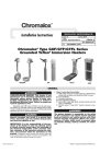
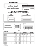
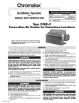
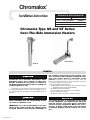
®
Chromalox
Installation Instructions
SERVICE REFERENCE
DIVISION
4
SALES
REFERENCE
SECTION
(Supersedes PD442-1)
GS, GT
PD442-2
161-562650-001
DATE
DECEMBER, 2004
Chromalox Type GS and GT Series
Over-The-Side Immersion Heaters
GSL3 or GTL3
GS or GT
GENERAL
FIRE/EXPLOSION HAZARD: This heater is not
intended for use in hazardous atmospheres where
flammable vapors, gases, liquids, or other combustible atmospheres are present as defined in
the National Electrical Code. Failure to comply can
result in explosion or fire.
Chromalox type GS and GT over-the-side immersion heaters
are designed primarily for corrosive baths and available in a variety of sheath materials. 316 stainless steel and titanium sheets are
standard.
Sheath corrosion can result in a ground fault
which, depending upon the solution being heated,
can cause an explosion or fire
IMPORTANT: It is the responsibility of the purchaser of the heater to make the ultimate choice
of sheath material based upon his knowledge of
© 2010 Chromalox, Inc.
the chemical composition of the corrosive solution, character of the materials entering the solution, and controls which he maintains on the
process. Chromalox cannot warrant any electric immersion
heater against failure by sheath corrosion if such failure is the result
of operating conditions beyond our control.
1. Heater Construction Characteristics
A. High quality resistance wire held in place by ceramic core and
magnesium oxide in various sheath materials.
B. Medium and low watt densities.
C. Epoxy filled cavity to prevent entry of contaminants.
D. Over-temperature protection.
E. Flexible conduit 3’ long with 6” leadwire extension.
The system designer is responsible for the safety
of this equipment and should install adequate
back-up controls and safety devices with their
electric heating equipment. Where the consequences of failure could result in personal injury
or property damage, back-up controls are essential.
INSTALLATION
ELECTRIC SHOCK HAZARD. Disconnect all power
before installing or servicing heater. Failure to do
so could result in personal injury or property damage. Heater must be installed by a qualified person in accordance with the National Electrical
Code, NFPA 70.
1. Before installing the type GS or GT heater, inspect it for possible
damage which may have occurred during shipment. Also, check
to insure that the line voltage is the same as that stamped on the
nameplate.
2. IMPORTANT: Mount heater in the tank so the
liquid level will always be above the effective
heated portion of the heater. Provide expansion
tank if necessary.
FIRE HAZARD. If the heater is not properly submerged, the heating elements will overheat and
could result in a fire or damaged equipment..
3. Where work will pass over or near equipment, additional protection, such as a guard, may be needed.
4. In an electroplating operation the heaters are not, under any circumstance, to be placed between the electrodes and the work.
5. When melting solids by direct immersion, a surface vent should
be provided to allow gases to escape. Operate the heater on half
voltage until melted material completely covers the heater area.
6. A drip loop is recommended to minimize passage of moisture
along wiring into terminal box and connections.
FIRE HAZARD. Since heaters are capable of developing high temperatures, extreme care should be
taken to: Since these heaters are capable of
developing high temperatures, extreme care
should be taken to:
A. Avoid contact between heater and combustible material.
B. Keep combustible materials far enough away to be free of the
effects of high temperatures.
WIRING
ELECTRIC SHOCK HAZARD. Any installation
involving electric heaters must be performed by a
qualified person and must be effectively grounded
in accordance with the National Electrical Code to
eliminate shock hazard.
Single phase or 3 phase heater circuit. Line voltage and/or current
exceeds thermostat or thermal fuses ratings (Figure 5). Dotted
line and L3 indicate 3 phase connections.
Ground
Green
Black
L3
L2
Black
L1
1. Electrical wiring to heater must be installed in accordance with
the National Electrical Code and local electrical codes by a qualified person.
2. When element wattages are not equal, heaters must not be connected in series.
Representative wiring diagrams for heaters with Single use
fuse (F) or Resetable fuse (RF) —
Single phase heater circuit using a SPST thermostat. Line Voltage
and/or current do not exceed thermostat or thermal fuse rating
(Figure 3).
Ground
Green
L2
Black
L1
*
Fused
Disconnect
*
Black
Heater
Figure 3
One Single phase heater or (3) single phase heaters equal in size
and each having a thermal fuse wired as a 3 phase heater circuit
using a DPST thermostat. Line voltage and current do not exceed
thermostat or thermal fuse(s) rating (Figure 4). Dotted line and L3
indicate 3 phase connections.
Green
*
*
*
*
*
*
L2
L1
Fused
Disconnect
Thermostat
*
Thermostat
(Customer Supplied)
Magnetic
Contactor
Thermal Fuses
Figure 5
Flexible Conduit Fittings —
Nut
Ferrule
Insert
Washer
Body
Conduit
Sealing
Insert
Thermal Fuse
Thermostat
L3
Heater
*
L1
Locknut
(Customer Supplied)
Ground
Black
Fused Disconnect
L2
Black
Thermal Fuses
(Customer Supplied)
Black
Black
Figure 4
Heater
1. Cut conduit. Slide nut and sealing insert onto the conduit.
2. Screw the ferrule insert into one end of the flexible conduit.
3. Seat the ferrule insert inside of the body, seat the sealing insert
and hand tighten the cap onto the body.
4. Repeat steps 1 thru 3 above for the other end of the conduit, after
pulling the wires.
5. If the fitting is used in a threaded hole, first thread the body into
the hole then follow steps 1 thru 3.
6. If the fitting is used thru an opening* use the locknut and plastic
washer to fasten it.
* Opening for 1/2” NPT thread is 7/8”.
OPERATION
1. Do not operate heater at voltages in excess of that stamped on the
heater since excess voltage will shorten heater life.
2. Always maintain a minimum of 2” of solution above the heated
portion of the element to prevent exposure of the effective heated
length. If the heater is not properly submerged, it may overheat,
create a hazard of fire and shorten heater life. Do not operate
heater if dry.
3. Sludge should not be allowed to build-up to the point where it
contacts heater, as this can lead to premature heater failure.
Sludge legs are standard on L-shaped heaters. Heater must not be
operated in sludge.
MAINTENANCE
ELECTRIC SHOCK HAZARD. Disconnect all power
before installing or servicing heater. Failure to do
so could result in personal injury or property damage. Heater must be installed by a qualified person in accordance with the National Electrical
Code, NFPA 70.
1. Heaters should be checked periodically for coating and corrosion
buildup and cleaned if necessary.
2. Tank should be checked regularly for sediment around the elements, as sediment can act as an insulator and shorten heater life.
3. Check for loose terminal connections.
4. If corrosion or moisture is indicated in the terminal housing,
check the conduit layout to correct the conditions that allow corrosion or moisture to enter the terminal housing.
THERMAL FUSE INSTALLATION/REPLACEMENT
ELECTRIC SHOCK HAZARD. Disconnect all power
before installing or servicing heater. Failure to do
so could result in personal injury or property damage. Heater must be installed by a qualified person in accordance with the National Electrical
Code, NFPA 70.
The Thermal fuse device must be properly installed and these
procedures followed or heater failure or fire may result.
A liquid level control is a must as an additional safety feature
to help minimize the possibility of fire.
1. Make sure all electrical power to the heater is shut-off.
2. Unscrew the head cover. Remove the wire nuts from the fuse
leads and save for re-use.
3. Remove the “Sealing Putty” and pull the Thermal fuse out of its
well. Clean the “putty” out of the well and save for re-use.
4. Check the Thermal fuse and the inside of the well to see if it is
wet. If wet inside, dry out well. Immerse the tube into the solution. If moisture appears again inside the well DO NOT use the
heater! Call the factory for further advice.
5. If the removed Thermal fuse is dry, proceed by using it as a guide
to cut and strip the wires of the new Thermal fuse.
6. Re-connect the Thermal fuse leads to the extension leads using
the original wire nuts.
7. Re-insert the Thermal fuse into the well making sure it is “fully
seated” to the bottom of the well.
8. Re-seal using the original “sealing putty” or an RTV type sealant.
9. Replace the head cover, return the heater to the tank.
10. Turn the power back on.
Thermal Fuse Temperature System —
Be sure and satisfied that your process bath tanks are as well
protected as possible from tank leaks, excessive evaporation, tank
refill failures, and worker error.
Grounded Electric Immersion Heaters are practical, efficient
and safe when used properly and installed in tanks that have proper solution levels, good ventilation, trained operators and safeguards such as liquid level controls and Thermal fuse over-temperature sensors.
Thermal fuse systems help reduce the hazards created by low
liquid levels and when properly seated and wired, they will cut
off the power to the heaters, thus avoiding the extreme temperatures resulting if solution levels are low enough to expose heater
hot zones.
Single Use Fuse (F) —
Sensor consists of a one-time thermal fuse which is standard
on all GS and GT over-the-side heaters.
The F thermal fuse is wired in series with the controller. To
operate properly the fuse must be fully seated to the bottom of the
thermowell tube. When the fuse “blows”, shut off the main power
to the heater, remove the spent fuse and install the new fuse. Refill
the tank to proper level prior to turning power back on.
Replacement thermal devices must be purchased from Chromalox.
Resettable Fuse (RF) —
Sensor consists of a Bi-metallic thermostatic sensor, an audible alarm, alarm relay, and reset button.
The RF System operates on the same principle as the F
except that the sensor does not “blow”. It operates as a Bi-metallic thermostat which “opens” and sounds the alarm. The reset button must be pushed to re-activate the heater and control, after the
solution level in the tank has been raised to the proper level.
FIRE/SHOCK HAZARD: Before replacing fuse,
make sure the cause of the “failure” has been
detected and corrected.
THERMAL FUSE INSTALLATION/REPLACEMENT (con’t.)
Thermal Fuse Replacement Protection Devices
Model Number
Used On
F, FM, FH
RF, RFM, RFH
Standard OTS Heater
FL, FLM, FLH
RFL, RFLM, RFLH
L-Shaped OTS Heater
F Amp Capacity - 25 Amps; RF Amp Capacity - 5 Amps;
Blank (low) Temp = 180˚F; M (Medium) Temp - 230˚F; H (High) Temp = 300˚F.
(Max Process Temperature)
Medium temp. most common for this style heater.
RF sensors require additional control components which include a Relay,
Audible Alarm, and Manual Reset Pushbutton.
Specify 120 or 240 V when ordering.
Limited Warranty:
Please refer to the Chromalox limited warranty applicable to this product at
http://www.chromalox.com/customer-service/policies/termsofsale.aspx.
2150 N. RULON WHITE BLVD., OGDEN, UT 84404
Phone: 1-800-368-2493
www.chromalox.com
TA - Q0 - EF
Litho in U.S.A.