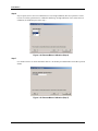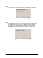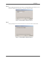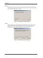
1
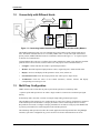
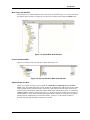
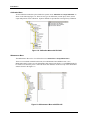
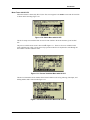
Herculine Smart Actuators Installation and Operation Manual Herculine Actuators with HART Communications Doc. No.: Industrial Measurement and Control 62-86-25-12 Revision: 0 Date: 5/05 Notices and Trademarks Copyright 2005 by Honeywell International Inc. Release 0 May, 2005 While this information is presented in good faith and believed to be accurate, Honeywell disclaims the implied warranties of merchantability and fitness for a particular purpose and makes no express warranties except as may be stated in its written agreement with and for its customers. In no event is Honeywell liable to anyone for any indirect, special or consequential damages. The information and specifications in this document are subject to change without notice. Honeywell are registered trademarks of Honeywell International Inc. Other brand or product names are trademarks of their respective owners. Industrial Measurement and Control Honeywell 1100 Virginia Drive Fort Washington, PA 19034 ii Installation and Operation Manual HercuLine Actuators with Hart Communications 5/05 About This Document Contacts World Wide Web The following lists Honeywell’s World Wide Web sites that will be of interest to our customers. Honeywell Organization WWW Address (URL) Corporate http://www.honeywell.com Industrial Measurement and Control http://www.honeywell.com/imc Telephone Contact us by telephone at the numbers listed below. Organization United States and Canada 5/05 Honeywell International Inc. Industry Solutions Phone Number 1-800-343-0228 1-800-525-7439 1-800-423-9883 Sales Service Technical Support Installation and Operation Manual HercuLine Actuators with Hart Communications iii About This Document References References The following list identifies all documents that may be sources of reference for material discussed in this publication. Document Title Herculine 10260 S Smart Actuator Specification and Model Selection Guide Doc ID 62-86-03-12 Herculine 2000 Series Specification and Model Selection Guide 61-86-03-14 Modbus RTU Serial Communications User Manual 51-52-25-66 Modbus RTU Serial Communications User Manual, Communication Interface for 10260S Actuator 51-52-25-103 10260S HercuLine® Smart Actuator. Installation, Operation and Maintenance Manual. 62-86-25-08 Herculine 2000 Series Installation, Operation, and Maintenance Manual 62-86-25-10 Definitions DD Device Description HCF HART iv HART Communication Foundation Highway Addressable Remote Transducer; HART is a registered trademark of HART Communication Foundation. SDC-625 Smart Device Configurator 625 H-FDCM Honeywell Field Device Configuration Manager Honeywell MC Toolkit Honeywell MC Toolkit SDC625 Pocket PC version Modbus Modbus is a registered trademark of Modicon, Inc. PWA Printed Wiring Assembly HC-275 HART Communicator 275; A product of Emerson Process Systems. HC-375 HART Communicator 375; A product of Emerson Process Systems. AMS Asset Management Solution; Is a trade mark of Emerson Electric Co. CE Conformité Europénne NEMA National Electrical Manufacturers Association CSA Canadian Standards Association Installation and Operation Manual HercuLine Actuators with Hart Communications 5/05 About This Document Definitions UL Underwriters Laboratories LED Light Emission Diode EEPROM Electrically Erasable Programmable Read-Only Memory 5/05 Installation and Operation Manual HercuLine Actuators with Hart Communications v Contents 1. INTRODUCTION ............................................................................1 1.1 Overview .......................................................................................................... 1 About Smart Actuator ............................................................................................................ 1 Enabling HART Communications .......................................................................................... 1 HART Protocol ...................................................................................................................... 1 1.2 Connectivity with Different Hosts.................................................................. 3 1.3 Multi Drop Configuration................................................................................ 3 1.4 DD Parameter Listing...................................................................................... 4 Menu Structure in the DD ...................................................................................................... 4 Menu Trees with SDC-625 .................................................................................................... 5 Menu Trees with HC-275....................................................................................................... 9 Menu Screens for AMS ....................................................................................................... 10 1.5 Methods Available in the DD........................................................................ 12 1.6 Calibration with SDC- 625 ............................................................................ 14 Remote Motor Field Calibration: .......................................................................................... 14 Current Input Calibration ..................................................................................................... 22 2. DD UPGRADING .........................................................................27 2.1 Overview ........................................................................................................ 27 Installing in HC-375 ............................................................................................................. 27 Installing in HC-275 ............................................................................................................. 27 Installing in AMS.................................................................................................................. 27 Installing for SDC-625 ......................................................................................................... 28 Installing in H-FDCM ........................................................................................................... 28 3. LIMITATIONS /NOT SUPPORTED..............................................29 4. TROUBLE SHOOTING ................................................................31 4.1 Command 48 Bytes / Device Status Byte / Alarms .................................... 31 Device Status Byte .............................................................................................................. 31 Software Status ................................................................................................................... 31 Alarm Status ........................................................................................................................ 32 HART Board Status ............................................................................................................. 32 Auto/Manual Mode .............................................................................................................. 33 Hardware Available ............................................................................................................. 33 5. 5/05 APPROVALS ...............................................................................35 Installation and Operation Manual HercuLine Actuators with Hart Communications vii Contents Table of Figures Figure 1-1: Connecting 10260S Actuator with HART Primary and Secondary Masters . 3 Figure 1-3: DD Menu Structure ....................................................................................... 4 Figure 1-4: Online Menu with SDC-625........................................................................... 5 Figure 1-5: Process Variables Menu with SDC-625........................................................ 5 Figure 1-6: Status Menu with SDC-625........................................................................... 6 Figure 1-7: Input Setup Group Menu with SDC-625 ....................................................... 7 Figure 1-8: Actuator Information Menu with SDC-625 .................................................... 7 Figure 1-9: Calibration Menu with SDC-625.................................................................... 8 Figure 1-10: Maintenance Menu with SDC-625 .............................................................. 8 Figure 1-11: Online Menu with HC-275 ........................................................................... 9 Figure 1-12: Process Variables Menu with HC-275 ........................................................ 9 Figure 1-13: Device Information Menu with HC-275 ....................................................... 9 Figure 1-14: Status Menu with HC-275 ......................................................................... 10 Figure 1-15: Device Menu with AMS ............................................................................. 10 Figure 1-16: Process Variables Menu with AMS ........................................................... 11 Figure 1-17: Configuration Properties Menu with AMS ................................................. 11 Figure 1-18: Maintenance Menu with AMS ................................................................... 11 Figure 1-19: Relay1 Menu with AMS............................................................................. 12 Figure 1-20: Remote Motor Calibration (Step 1) ........................................................... 14 Figure 1-21: Remote Motor Calibration (Step 2) ........................................................... 14 Figure 1-22: Remote Motor Calibration (Step 3) ........................................................... 15 Figure 1-23: Remote Motor Calibration (Step 4) ........................................................... 15 Figure 1-24: Remote Motor Calibration (Step 5) ........................................................... 15 Figure 1-25: Remote Motor Calibration (Step 6) ........................................................... 16 Figure 1-26: Remote Motor Calibration (Step 7) ........................................................... 16 Figure 1-27: Remote Motor Calibration (Step 8) ........................................................... 17 Figure 1-28: Remote Motor Calibration (Step 9) ........................................................... 17 Figure 1-29: Remote Motor Calibration (Step 10) ......................................................... 18 Figure 1-30: Remote Motor Calibration (Step 11) ......................................................... 18 Figure 1-31: Remote Motor Calibration (Step 12) ......................................................... 19 Figure 1-32: Remote Motor Calibration (Step 13) ......................................................... 19 Figure 1-33: Remote Motor Calibration (Step 14) ......................................................... 20 Figure 1-34: Remote Motor Calibration (Step 15) ......................................................... 20 Figure 1-35: Remote Motor Calibration (Step 16) ......................................................... 21 Figure 1-36: Remote Motor Calibration (Step 17) ......................................................... 21 Figure 1-37: Remote Motor Calibration (Step 18) ......................................................... 21 Figure 1-38: Current Input Calibration (Step 1) ............................................................. 22 Figure 1-39: Current Input Calibration (Step 2) ............................................................. 22 Figure 1-40: Current Input Calibration (Step 3) ............................................................. 23 Figure 1-41: Current Input Calibration (Step 4) ............................................................. 23 Figure 1-42: Current Input Calibration (Step 5) ............................................................. 23 Figure 1-43: Current Input Calibration (Step 6) ............................................................. 24 Figure 1-44: Current Input Calibration (Step 7) ............................................................. 24 Figure 1-45: Current Input Calibration (Step 8) ............................................................. 24 Figure 1-46: Current Input Calibration (Step 9) ............................................................. 25 Figure 1-47: Current Input Calibration (Step 10) ........................................................... 25 Figure 1-48: Current Input Calibration (Step 11) ........................................................... 25 Figure 1-49: Current Input Calibration (Step 12) ........................................................... 26 Figure 1-50: Current Input Calibration (Step 13) ........................................................... 26 Figure 2-1: Installing DD installation kit in AMS (Step 1)............................................... 27 Figure 2-2: Installing DD installation kit in AMS (Step 2)............................................... 28 Figure 4-1: Device Status Byte in AMS ......................................................................... 31 5/05 Installation and Operation Manual HercuLine Actuators with Hart Communications ix Contents Figure 4-2: Software Status Byte in AMS ......................................................................31 Figure 4-3: Alarm Status Byte in AMS ...........................................................................32 Figure 4-4: HART Board Status Byte in AMS ................................................................32 Figure 4-5: Auto/Manual Mode Status in AMS...............................................................33 Figure 4-6: Hardware Available Status in AMS..............................................................33 x Installation and Operation Manual HercuLine Actuators with Hart Communications 5/05 Introduction 1. Introduction 1.1 Overview About Smart Actuator Honeywell's HercuLine series actuators are industrially rated rotary control actuators and are precision engineered for exceptional reliability, accurate positioning, and low maintenance. Designed for very precise positioning of dampers and quarter turn valves in the power and processing industries, these actuators perform especially well in extremely demanding environments requiring continuous-duty, high reliability and low maintenance. Precise positioning of the actuator is achieved through the state-of-the-art motor control and positioning electronics. The motor starts and stops instantaneously, preventing overshoot and hunting. Positioning repeatability of 0.2 % span or better is achievable for extremely tight process control to take full advantage of modern controllers. A no-burnout synchronous induction motor is combined with a heavy-duty precision-machined output worm gear mesh providing a responsive, low maintenance, and non-backdriving actuator. Accidental stalls up to 100 hours can be withstood without damage to the gear train. End-of-travel limit switches are provided as standard to prevent damage to the valve or damper and are backed up by mechanical stops. Honeywell electric actuators provide instantaneous response to a demand signal, eliminating system nonlinearity due to dead time. Additionally, since the actuator is electric, the costs associated with providing and maintaining a clean, dry air supply is eliminated. A heavy duty cast crank arm and precision rod-end bearing is provided with each actuator. Crank arms can be positioned at any angle on the output shaft and an adjustable radius is provided to allow flexibility in linkage set-up. All actuators are equipped with a manual hand wheel for operation during loss of power or installation. A local auto/manual hand switch can be provided for local operation and has an “out of auto” contact to annunciate that condition. Enabling HART Communications The HART Communications option enables the HercuLine series actuators to be able to connect to a HART network and will provide communication interface for both primary and secondary HART masters. The primary master would be an IO card/interface (or H-FDCM or AMS) and the secondary master would be an HC-275/375 handheld (or Honeywell MC Toolkit) connected at the same time. The HART Solution enables the actuators to provide digital communications over the 4-20mA signal wire. The same HART Communication option supports all Herculine series actuators 10260S series, 11280S series and the 2001/2002. HART Protocol In a typical process control environment, field devices such as pressure, level, and temperature transmitters and valve positioners provide the physical connection to the process. These devices allow the control system to monitor and manipulate process conditions. Smart field devices, such as HART devices, maintain a database of process configuration, identification, and diagnostic information in memory. These devices use the HART digital protocol (governed and maintained by the HART Communication Foundation) to communicate information to the control and asset management system. HART is an open smart field device protocol available for use by all member companies. The word HART is an acronym that stands for Highway Addressable Remote Transducer. For more about HART and HCF, visit their web site at: http://www.hartcomm.org/. 5/05 Installation and Operation Manual HercuLine Actuators with Hart Communications 1 Introduction 1.2 Connectivity with Different Hosts 4-20 mA Line Handheld Terminal (HC275/375 /SDC Pocket PC) Control System or Other Host Application (SDC-625 /AMS / HFDCM) Figure 1-1: Connecting 10260S Actuator with HART Primary and Secondary Masters The HART communicator (HC-275/375) communicates to the Actuator on the 4-20mA input current lines. The HART communicator acts as a secondary HART master. On the same input current lines a primary master (AMS/H-FDCM) can also be connected as shown in the Figure 1-1. A request-response is the basis for communication. A HART Master allows the user to configure the Actuator, Monitor the output values, Diagnose potential problems from a remote location, such as control room. The purpose of the communication is to: 1.3 • Configure: Define and enter the actuator’s operational parameters • Monitor: Read the input and output parameter values, engineering units, Alarms and the status. • Display: Receives and displays all the parameter values, status, Alarms etc. • Check Position value: Check the output position value with respect to input current. • Troubleshoot: Check the status of the actuator (hardware, software, Alarms) and display corresponding error message to user. Multi Drop Configuration HART Actuator can be used either in point-to-point mode operations or multi-drop mode. A point-to-point mode operation is one where a single actuator is connected to a 4-20mA input signal directly In multi-drop mode, more than 1 actuator is using the single analog 4-20mA input signal. The poll address of the actuator is set to 0 when the device comes out of factory. Each actuator connected in the multi drop network should have a unique poll address. Before connecting the devices in multidrop mode the user needs to configure a unique poll address for each device using any of the HART Host in point-to-point mode before connecting them in the mult-drop network. The multi-drop mode operation is used in the control applications like Proportional flow using Multiple Actuators, Split Valve configuration as given in section 6 of reference document ID 62-86-25-08. 5/05 Installation and Operation Manual HercuLine Actuators with Hart Communications 3 Introduction 1.4 DD Parameter Listing Menu Structure in the DD 1.Position 2.PV Current 3.Input 4.Temperature 5.Deviation 6.Input LRV 7.Input URV 8.Deadband 1.Process Variables 1.Device Setup 2.Position 3.PV current 4.Input 5.Temperature 2.Diagnostic/ Services 3.Configuration 1.Setup 2.Position Unit 3.Temp Unit 4.Calibration 1.Current Input 2.Motor 3.Current Output 4.Position Sensor 5.Maintenance 6.Device Information 7.Review 1.Poll Address 2.Tag 3.Message 4.Model 5.Descriptor 6.Device Id 7.No of Req Preambles 8.Fld Dev Rev 9.Universal Rev 10.Software Rev 11.Hardware Rev 1.Actuator Status 2.Position Test 3.Master Reset 4.Restore Factory Config 1.Poll Address 2.Tag 3.Message 4.Model 5.Descriptor 6.Final Asmbly No 7.Install Date 1.Temp Lo 2.Temp Hi 3.Acc Stall Time 4.Acc. Starts 5.Relay 1 Count 6.Relay 2 Count 7.Relay 3 Count 8.Relay 4 Count 9.Region Count 0 10.Region Count 1 11.Region Count 2 12.Region Count 3 13.Region Count 4 14.Region Count 5 15.Region Count 6 16.Region Count 7 17.Region Count 8 18.Region Count 9 19.Total Degrees 20.Save Maintenance Data 21.Reset Stats 1.Software Status 2.Alarm Status 3.HART Board Sts 4.Mode Status 5.Hardware Status 1.Input 2.Keybrd Auto/Man 3.Characterization 4.Alarms 5.Current Output 6.Digital Input 7.Display 8.Lockout 9.Actuator Info 1.Direction 2.Failsafe Hi Type 3.Failsafe Lo Type 4.Failsafe Hi Val 5.Failsafe Lo Val 6.Input Filter Type 7.Low Pass Val 8.Model 1.Auto/Manual 1.Tx Function 2.Custom Char 3.X0-X20&Y0-Y20 1.Relay (n)/Alarm 1.Current Input Calibration 2.Restore Current Input Calibration 1.Remote Motor Field Calibration 2.Remote Motor Factory Calibration 3.Restore Motor Calibration 1.Current Output Calibration 2.Restore Current Output Calibration 1.Position Sensor Calibration 2.Restore NCS Calibration 1.Relay (n) SP1 Type 2.Relay (n) SP1 Val 3.Relay (n) SP1 Scale 4.Relay (n) SP1 Event 5.Relay (n) SP2 Type 6.Relay (n) SP2 Val 7.Relay (n) SP2 Scale 8.Relay (n) SP2 Event 9.Relay (n) Hysteresis 1.Current O/P Type 1.Digital Input Type 2.User Position 1.Dec Pt Location 1.Keyboard Lock 2.Auto/Man Lock 1.Motor Speed 2.Power 3.Line Frequency 4.Rotation 5.Torque 6.Actuator Tag 7.Last Calib Date 8.Manufacture Date 9.Repair Type Figure 1-2: DD Menu Structure 4 Installation and Operation Manual HercuLine Actuators with Hart Communications 5/05 Introduction Menu Trees with SDC-625 When the device is loaded with SDC-625, the main menu will look like Figure 1-3. The left pane shows the complete menu structure. The right list view shows the variables present under the Online menu. Figure 1-3: Online Menu with SDC-625 Process Variables Menu The process variables menu will look like as shown in the Figure 1-4. Figure 1-4: Process Variables Menu with SDC-625 Diagnostic/Service Menu All the device status variables are present under the “Online/Device setup/Diag Service/Actuator status” menu. The detailed status bits of each variable can be displayed by right clicking on the variable in the right pane and selecting the Display value option in the context menu. The status selections are Software Status, Alarm Status; HART board Status, Mode Status and Hardware Status. An example the “Software status” variable is shown in the Figure 1-5. The Software status variable gives the status of the Main PWA’s software status including input signal Failsafe condition. A checked box will indicate that the particular condition has occurred in the actuator. In Figure 1-5, the Failsafe checkbox is checked, indicating that the Failsafe condition has occurred. 5/05 Installation and Operation Manual HercuLine Actuators with Hart Communications 5 Introduction Figure 1-5: Status Menu with SDC-625 The Alarm status byte tells the status of the programmable Alarms either ON or OFF. The bits in the Alarm status byte are 1. Alarm / Relay1 Set 2. Alarm / Relay2 Set 3. Alarm / Relay3 Set 4. Alarm / Relay4 Set 5. Stall Alarm Set 6. Position Sensor Fail The HART Board status byte tells the software status of the HART PWA. The bits in the HART Board status byte are 1. EEPROM Fail 2. RAM Fail 3. FLASH Fail 4. MODBUS Communication Fail All the 3 bytes mentioned above are critical for the functionality of the actuator. The rest of the bytes mode status and hardware status are for information purpose only. Mode status informs the user of the present mode of the Actuator (Auto or Manual). The mode status selections are 6 1. Auto/Manual Mode - The current mode of the Actuator (Auto or Manual). If this bit is checked then the actuator is in Manual Mode. 2. Manual Front Panel - The status of the Actuator front panel switch. If this bit is checked the actuator front panel switch is put in Manual mode. Installation and Operation Manual HercuLine Actuators with Hart Communications 5/05 Introduction 3. Manual External Switch - The status of the External Auto/Manual switch. If this is checked the actuator External Switch is put in Manual mode. Setting of any of the last two bits in Manual mode will set the mode of the actuator to Manual. The hardware status gives availability of the actuator hardware resources. The bits present are: 1. Relay board 1 (Relay 1 & Relay 2) 2. Relay board 2 (Relay 3 & Relay 4) 3. Display/Keyboard 4. HART Communication Card If any of the bits are checked, it means that they are available in the Actuator. Configuration Menu All the configuration parameters are arranged under the “Online/Device setup/Configuration” menu. The input signal configuration parameters are present in the setup/input menu as shown in the Figure 1-6. Figure 1-6: Input Setup Group Menu with SDC-625 The actuator information such as motor speed, torque etc. is available under the menu “Online/Device setup/Configuration/setup/Actuator info”. The actuator information screen is shown in the Figure 1-7. Figure 1-7: Actuator Information Menu with SDC-625 5/05 Installation and Operation Manual HercuLine Actuators with Hart Communications 7 Introduction Calibration Menu All the calibration methods are placed under the separate menu “Online\Device setup\Calibration” as shown in the following Figure 1-8. There are four types of calibrations; current input, motor, current output and position sensor calibration. Separate methods are provided for restoring factory calibration. Figure 1-8: Calibration Menu with SDC-625 Maintenance Menu The Maintenance data can be viewed from the menu “Online/Device Setup/Maintenance” There are two methods available in this menu, Save Maintenance Data and Reset stats. Save Maintenance Data is used to save the maintenance data (shown in the Figure 1-9) to EEPROM and will be retained even when the power is removed. Reset stats method is used to reset any of the maintenance statistics shown in the Figure 1-9. Figure 1-9: Maintenance Menu with SDC-625 8 Installation and Operation Manual HercuLine Actuators with Hart Communications 5/05 Introduction Menu Trees with HC-275 When the actuator is detected by HC-275, the first screen appears is the Online screen and will look like as shown in the following Figure 1-10. Figure 1-10: Online Menu with HC-275 The device setup screen and the other screens will look similar to the menu structures given for SDC625. The process variable menu screen is shown in the Figure 1-11. There are few more variables in this menu, which are not visible. Use the Arrow keys present on the HC-275 keyboard to scroll through all the available variables under the menu. Figure 1-11: Process Variables Menu with HC-275 The Device information menu contains all the HART variables such as Tag, Message, Descriptor, and Polling Address and is shown in the Figure 1-12. Figure 1-12: Device Information Menu with HC-275 5/05 Installation and Operation Manual HercuLine Actuators with Hart Communications 9 Introduction The device status menu contains all the status variables and is shown in the following Figure 1-13. Figure 1-13: Status Menu with HC-275 Menu Screens for AMS Some of the menu screens with AMS are presented here. When a device is detected with AMS and the user right clicks on it, the device menu will appear as shown in the Figure 1-14. Figure 1-14: Device Menu with AMS Calibration methods are presented in the Calibrate menu. All the diagnostic methods such as Master reset, position test are presented under Diagnostic and Test menu. When you select the Process Variables menu, the following dialog box is displayed (Figure 1-15). 10 Installation and Operation Manual HercuLine Actuators with Hart Communications 5/05 Introduction Figure 1-15: Process Variables Menu with AMS All the process variables that change dynamically with the applied process are presented here and are read only. The parameters to be configured are presented in the configuration properties dialog box (Configuration Properties menu) with separate tabs as shown in the Figure 1-16. Figure 1-16: Configuration Properties Menu with AMS The Maintenance Data menu in AMS looks as shown in the Figure 1-17. Figure 1-17: Maintenance Menu with AMS 5/05 Installation and Operation Manual HercuLine Actuators with Hart Communications 11 Introduction The example Relay menu in AMS is shown in the Figure 1-18: Figure 1-18: Relay1 Menu with AMS 1.5 Methods Available in the DD 1. Master Reset 2. Position Test 3. Restore factory configuration 4. Save Maintenance Data 5. Reset Stats 6. Current input calibration 7. Restore current input calibration 8. Current output calibration 9. Restore current output calibration 10. Remote Motor field calibration 11. Remote Motor factory calibration 12. Restore Motor calibration 13. Position Sensor calibration 14. Restore NCS calibration The methods 1-3 are present under the menu “Online/Device setup/Diag Service”. Master Reset: This method resets the actuator; this operation is same as the actuator Powered OFF and ON. Position Test: This method instructs the Herculine Actuator to move the motor from current position to a different location (this depends on current position of the motor) and to return back to the original position, the method reports any problem found during the execution. 12 Installation and Operation Manual HercuLine Actuators with Hart Communications 5/05 Introduction Restore factory config: Restores the user configuration to the factory configuration. Methods 4-5 are present under the menu “Online/Device setup/Maintenance” menu. Save Maintenance Data: Saves all the maintenance data to the EEPROM. Since the data is stored in a Non-Volatile memory the values will be retained even the actuator power is removed. Reset Stats: Resets the any or all of the maintenance data variables to zero value. All the calibration methods 6-14 are arranged under the menu “Online/Device setup/Calibration” Current Input calibration: This procedure calibrates the Actuator's remote current input field. Before Running the Method, ensure that the calibrated 4-20mA current source is connected at input terminals of the actuator. Restore Current Input calibration: Restores the user current input calibration to the factory values. Current Output calibration: This procedure calibrates the Actuator's remote current output field. Before running the method, make sure that the Actuator's current output type has already been configured and a voltmeter is connected across a 250-ohm resistor, which is connected across the current output terminals of the actuator. Restore Current Output calibration: Restores the user current output calibration to the factory values. Remote Motor Field Calibration: This procedure calibrates the Actuator's Actuation span Remote Motor Factory Calibration: This procedure calibrates a position Sensor that has been replaced in the field. WARNING: performing this procedure will destroy the original factory motor calibration. Before calibrating, ensure that the Motor direction (CCW) and the engineering units are already configured. This calibration must be a complete 100% SPAN calibration and in the CCW direction. Restore Motor calibration: Restores the user motor calibration to the factory values. Position Sensor calibration: This method is to calibrate the position sensor when the sensor output is incorrect (or) the position sensor in the actuator has been replaced (or) the position sensor adjustment has been disturbed. Restore Position calibration: Overwrites the original calibration with the user remote factory calibration. An example calibration method is given in section 1.6. 5/05 Installation and Operation Manual HercuLine Actuators with Hart Communications 13 Introduction 1.6 Calibration with SDC- 625 Remote Motor Field Calibration: An example is given here for calibrating remote motor field with the detailed steps including windows dialogs. This calibration is performed with SDC-625. When the remote motor field calibration method is executed, the first dialog appears is as shown below: Step1 Figure 1-19: Remote Motor Calibration (Step 1) Press ‘OK’ to proceed with the calibration or press ‘Abort’ to abort the method. You can press Abort at any stage of the method execution to abort the field calibration. If you abort in the middle of the method execution the calibration values will not be saved. You need to perform all the steps (till the end of the method) to complete the calibration. If you click OK, the method will proceed to the step 2. Please click OK in step 2 to proceed to step 3, step 4, step 5 and Step 6. The OK or Abort buttons will not be enabled in Step 3, 4 and 5. Step 2 If the engineering unit is not configured to %, this step will automatically set the unit to % before proceeding to step 3. Figure 1-20: Remote Motor Calibration (Step 2) 14 Installation and Operation Manual HercuLine Actuators with Hart Communications 5/05 Introduction Step 3 This step selects the Motor Calibration group in the actuator. Figure 1-21: Remote Motor Calibration (Step 3) Step 4 Step 4 and 5 invokes and enables the Motor calibration respectively. Figure 1-22: Remote Motor Calibration (Step 4) Step 5 Figure 1-23: Remote Motor Calibration (Step 5) 5/05 Installation and Operation Manual HercuLine Actuators with Hart Communications 15 Introduction Step 6 Step 6 requests user to select Low calibration (Lo Cal) or high calibration (Hi Cal) to perform. User has to select Lo cal first, perform the low calibration and then go to High calibration. If user selects the Low calibration, the calibration proceeds to step 7. Figure 1-24: Remote Motor Calibration (Step 6) Step 7 User needs to enter Low motor calibration value in % in the Box provided and then Click OK to proceed further. Figure 1-25: Remote Motor Calibration (Step 7) 16 Installation and Operation Manual HercuLine Actuators with Hart Communications 5/05 Introduction Step 8 This step just displays the user-selected value and user has to click OK to continue with the method. Figure 1-26: Remote Motor Calibration (Step 8) Step 9 This step will wait till the motor is placed in the user requested position before proceeding to the next step. Both the OK and Abort buttons are disabled here. The displayed message in the dialog box depends on the current position of the actuator. This can be either Decreasing Motor position or Increasing Motor position message. Once the motor is placed in the user requested position the calibration proceeds to the next step Figure 1-27: Remote Motor Calibration (Step 9) 5/05 Installation and Operation Manual HercuLine Actuators with Hart Communications 17 Introduction Step 10 The final position may not be exactly the same value requested by the user. There may be a small difference between the user requested value and the set position value. Check the position value displayed in the actuator front panel display. Adjust the motor position using Handwheel or Auto/Manual switch to the requested value and then proceed with the next step. Figure 1-28: Remote Motor Calibration (Step 10) Step 11 Select the High calibration (Hi Cal) in this step and click OK to continue. Figure 1-29: Remote Motor Calibration (Step 11) 18 Installation and Operation Manual HercuLine Actuators with Hart Communications 5/05 Introduction Step 12 Enter the High calibration position value in this step. The high calibration value should be 10% more than the low calibration value entered in step 7. Click OK to continue the method. Figure 1-30: Remote Motor Calibration (Step 12) Step 13 This step just displays the user-selected value and user has to click OK to continue with the method. Figure 1-31: Remote Motor Calibration (Step 13) 5/05 Installation and Operation Manual HercuLine Actuators with Hart Communications 19 Introduction Step 14 This step will wait till the motor is placed in the user requested position before proceeding to the next step. Both the OK and Abort buttons are disabled here. Once the motor is placed in the user requested position the calibration proceeds to the next step Figure 1-32: Remote Motor Calibration (Step 14) Step 15 The final position may not be exactly the same value requested by the user. There may be a small difference between the user requested value and the set position value. Check the position value displayed in the actuator front panel display. Adjust the motor position using Hand wheel or Auto/Manual switch to the requested value and then proceed with the next step. Figure 1-33: Remote Motor Calibration (Step 15) 20 Installation and Operation Manual HercuLine Actuators with Hart Communications 5/05 Introduction Step 16 Once the Low and High calibrations are completed select End and press OK to complete the calibration method. Figure 1-34: Remote Motor Calibration (Step 16) Step 17 Click OK here to terminate the Motor field calibration. Figure 1-35: Remote Motor Calibration (Step 17) Step 18 The dialog box displays the Motor field calibration completed message. Figure 1-36: Remote Motor Calibration (Step 18) 5/05 Installation and Operation Manual HercuLine Actuators with Hart Communications 21 Introduction Current Input Calibration An example is given here for calibrating Current Input with the detailed steps including windows dialogs. This calibration is performed with SDC-625. When the Current Input calibration method is executed, the first dialog box appears is as shown below: Step 1 Click OK to proceed with the calibration or click Abort to abort the method. You can press Abort at any stage of the method execution to abort the Input calibration. If you abort in the middle of the method execution the calibration values will not be saved. You need to perform all the steps (till the end of the method) to complete the calibration. If you click OK, the method will proceed to the step 2. Click OK in step 2 to proceed to step 3, step 4, step 5 and Step 6. The OK or Abort options will not be enabled in Step 3, 4 and 5. Figure 1-37: Current Input Calibration (Step 1) Step 2 Make sure that the calibrated 4-20mA input current source is connected at the input terminals of the actuator before proceeding with clicking OK button. Figure 1-38: Current Input Calibration (Step 2) 22 Installation and Operation Manual HercuLine Actuators with Hart Communications 5/05 Introduction Step 3 This step selects the Input type Calibration group in the actuator. Figure 1-39: Current Input Calibration (Step 3) Step 4 Step 4 and 5 invokes and enables the Input calibration respectively Figure 1-40: Current Input Calibration (Step 4) Step 5 Figure 1-41: Current Input Calibration (Step 5) 5/05 Installation and Operation Manual HercuLine Actuators with Hart Communications 23 Introduction Step 6 Step 6 will activate the Zero Calibration Function Figure 1-42: Current Input Calibration (Step 6) Step 7 Step 7 ensures that Zero calibration is activated. User has to set the Low Calibration Point in the external input source (4mA) before pressing OK and proceeding to next step. Figure 1-43: Current Input Calibration (Step 7) Step 8 This step displays that the zero calibration is completed. Figure 1-44: Current Input Calibration (Step 8) 24 Installation and Operation Manual HercuLine Actuators with Hart Communications 5/05 Introduction Step 9 Once the zero calibration is completed the method performs the span calibration Figure 1-45: Current Input Calibration (Step 9) .Step 10 Span calibration will be performed from step 9. User has to set the High Calibration point (20mA) in the external source before proceeding to next step. Figure 1-46: Current Input Calibration (Step 10) Step 11 Steps 11 and 12 will perform the span calibration and terminate the calibration method. Figure 1-47: Current Input Calibration (Step 11) 5/05 Installation and Operation Manual HercuLine Actuators with Hart Communications 25 Introduction Step 12 Figure 1-48: Current Input Calibration (Step 12) Step 13 This dialog box shows that Input calibration is completed. All the other calibration methods (current output and Non-contact sensor) are similar to the above examples. Each step in the method will direct the user if an action is required from user end. Figure 1-49: Current Input Calibration (Step 13) 26 Installation and Operation Manual HercuLine Actuators with Hart Communications 5/05 2. DD Upgrading 2.1 Overview If your HART Host does not have the Herculine actuator DD installed, please upgrade your Host with the latest actuator DD by downloading from http://www.honeywell.com/imc The link contains the DD installation files for the following Hosts: 1. Herculine actuators DD file for HC-375 2. Herculine actuators DD file for HC-275. 3. Herculine actuator DD installation kit for AMS. Installing in HC-375 Use the 375 Easy Upgrade utility received with the HC-375 to install the DD file (*.hdd, *hhd) onto HC375. Installing in HC-275 To load the DD onto HC-275 you need to have 275 DD upgrade hardware & software. Please contact Emerson Service center if you don’t have the HC-275 DD upgrade facility. Installing in AMS The downloaded AMS device installation kit can be installed only on PC’s where AMS is installed. This kit is tested for only AMS 6.0, 6.1 and 6.2 versions and is not tested with any other AMS versions. 1. Unzip the file and extract the contents to a folder on the PC where AMS is installed. 2. Select Start > Programs/AMS/Add Device Manually. In the dialog box, click Next to proceed. 3. A new dialog box will appear asking to select the source directory where the device installation kit present as shown in the Figure 3.1. Select the directory where the Ddinstal.ini file is located. This file will present in the directory where the DD installation kit is extracted (Extracted Directory/Herculine/Ddinstal.ini). Click Next to proceed. Figure 2-1: Installing DD installation kit in AMS (Step 1) 5/05 Installation and Operation Manual HercuLine Actuators with Hart Communications 27 DD Upgrading 4. A new dialog will appear showing the Device DD present in the installation kit as shown in the below Figure 3.2: Figure 2-2: Installing DD installation kit in AMS (Step 2) 5. Click Next to proceed further. Once all the steps are finished a message will appear saying “Device installation successful”. Installing for SDC-625 1. Copy the DD file (.fms file) to where the device database for SDC is present. 2. If the DD IDE is already installed, the device database path should be C:\HCF\DDL\Library. 3. Copy the .fms file into the patch “C:\HCF\DDL\Library\000017\0005”. If the path is not present create one. Installing in H-FDCM 28 1. Copy the DD file (.fms file) to any location in the PC, 2. Open the H-FDCM client, and select Tools/Add DD File from the menu. A dialog box will appear asking to select the .fms file. 3. Select the copied .fms file and select Open to proceed further. 4. The DD file Uploaded successfully message is displayed. Installation and Operation Manual HercuLine Actuators with Hart Communications 5/05 3. Limitations /Not Supported • 5/05 Burst Mode is not supported Installation and Operation Manual HercuLine Actuators with Hart Communications 29 4. Trouble Shooting 4.1 Command 48 Bytes / Device Status Byte / Alarms All the device status and command 48 screens presented here are taken with AMS. Device Status Byte The string will be shown with the red color background if that particular condition is set in the actuator. Refer HART Protocol documentation for specific meaning of the device status byte strings. Figure 4-1: Device Status Byte in AMS Software Status This byte gives the software and hardware status of the Actuator Main PWA. The Failsafe condition will set if the input signal is out of limits (not within 4-20mA). Figure 4-2: Software Status Byte in AMS 5/05 Installation and Operation Manual HercuLine Actuators with Hart Communications 31 Troubleshooting Alarm Status This byte gives the Alarms status of the actuator including stall condition and Rivitz failure. All the alarms are user configurable. Figure 4-3: Alarm Status Byte in AMS HART Board Status The HART Board status byte gives the software and hardware status of HART PWA. • If Modbus communication Fail bit is set, there could be a problem with the Modbus communication in the actuator. This problem will be cleared automatically once the Modbus communication restores. If the problem persists for long time, run the Master Reset method to resolve the problem or Power OFF and Power ON the actuator. • Replace the HART PWA board with new one if RAM or EEPROM or FLASH failure happens. All the above three bytes are command 48 bytes and are critical to the operation of the actuator. Figure 4-4: HART Board Status Byte in AMS 32 Installation and Operation Manual HercuLine Actuators with Hart Communications 5/05 Trouble Shooting Auto/Manual Mode This byte gives Auto/Manual mode status of the actuators External and Front panel switch. If any of the bits is set then the actuator is in Manual mode. Figure 4-5: Auto/Manual Mode Status in AMS Hardware Available This byte gives the hardware available with actuator. Each relay board has two Relays/Alarms. The two bytes are for information purpose only. Figure 4-6: Hardware Available Status in AMS 5/05 Installation and Operation Manual HercuLine Actuators with Hart Communications 33 5. Approvals The Herculine actuator with HART Communications is approved for the following standards 5/05 1. CE 2. UL 3. CSA 4. NEMA Installation and Operation Manual HercuLine Actuators with Hart Communications 35 Industrial Measurement and Control Honeywell 1100 Virginia Drive Fort Washington, PA 19034 62-86-25-12 0505 Printed in USA www.honeywell.com/imc