1
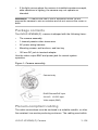
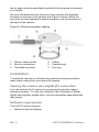
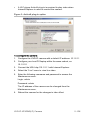
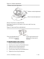
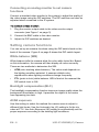
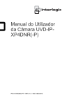
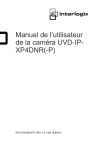
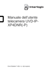
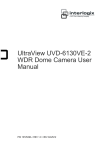
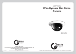
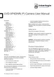
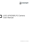
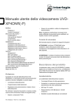
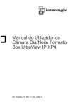
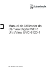
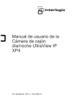
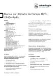
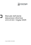
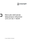
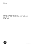
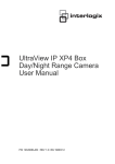
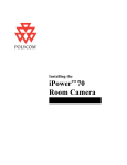
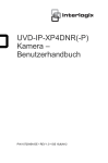
UVD-IP-XP4DNR(-P) Camera User Manual P/N 1072545A-EN • REV 1.0• ISS 18JUN12 Copyright Trademarks and patents Manufacturer © 2012 UTC Fire & Security. All rights reserved. The Interlogix and UltraView names and logos are trademarks of UTC Fire & Security. Other trade names used in this document may be trademarks or registered trademarks of the manufacturers or vendors of the respective products. UTC Fire & Security Americas Corporation, Inc. 2955 Red Hill Avenue, Costa Mesa, CA 92626 5923, USA. Authorized EU manufacturing representative: UTC Fire & Security B.V. Kelvinstraat 7, 6003 DH Weert, The Netherlands Certification N4131 FCC compliance Class A: This equipment has been tested and found to comply with the limits for a Class A digital device, pursuant to part 15 of the FCC Rules. These limits are designed to provide reasonable protection against harmful interference when the equipment is operated in a commercial environment. This equipment generates, uses, and can radiate radio frequency energy and, if not installed and used in accordance with the instruction manual, may cause harmful interference to radio communications. Operation of this equipment in a residential area is likely to cause harmful interference in which case the user will be required to correct the interference at his own expense. ACMA compliance Notice! This is a Class A product. In a domestic environment this product may cause radio interference in which case the user may be required to take adequate measures. Canada This Class A digital apparatus complies with Canadian ICES003. Cet appareil numérique de la class A conforme à la norme NMB003 du Canada. European Union directives 2004/108/EC (EMC directive): Hereby, UTC Fire & Security declares that this device is in compliance with the essential requirements and other relevant provisions of Directive 2004/108/EC 2002/96/EC (WEEE directive): Products marked with this symbol cannot be disposed of as unsorted municipal waste in the European Union. For proper recycling, return this product to your local supplier upon the purchase of equivalent new equipment, or dispose of it at designated collection points. For more information see: www.recyclethis.info. Contact information For contact information see our Web site: www.interlogix.com, www.utcfssecurityproducts.eu Contents Introduction 2 Product description 2 Features 2 User guidelines 2 Package contents 3 Plenum-compliant cabling 3 Installation 4 Viewing the camera via a digital (IP) connection 4 Software requirements 4 Connecting analog cables 6 Installing the camera 6 Angle adjustment 6 Zoom and focus adjustment 7 Connecting an analog monitor to set camera functions 8 Setting camera functions 8 White balance (WB) 8 Backlight compensation (BLC) 8 AI/AE exposure 8 Day/Night 9 Resolution 9 Flickerless control 9 Reset to factory default settings 10 UVD-IP-XP4DNR(-P) Camera 1 - EN Introduction This user manual provides basic information on setting up and using the UVD-IP-XP4DNR(-P) Camera. Product description The UVD-IP-XP4DNR(-P) color video camera uses a digital signal processor (DSP) to process video signals. The video camera includes a microcontroller to provide high-quality images in changing lighting environments with high-color reproduction and sharp pictures. Features Camera features include: • H.264-SVC video compression with multistream capability. • Pixim Seawolf technology • Excellent performance in almost any lighting conditions • Supports up to 4CIF resolution (540 HTVL analog). • True day/night (removable IR cut filter) • Long life and high reliability. • DIP switch control of camera settings. • Power over Ethernet (PoE) or Isolated switching power 12 VDC or 24 VAC. • Vandal-resistant housing. User guidelines Use the following guidelines: • Take appropriate safety precautions while completing programming after installation. • Always use a proper PoE switch or a 12 VDC or 24 VAC UL listed Class 2 power supply to power the camera. • Do not use the camera outside the temperature range specifications: -30 to +50°C (-22 to +122°F) EN - 2 UVD-IP-XP4DNR(-P) Camera • If the light source where the camera is installed experiences rapid, wide-variations in lighting, the camera may not operate as intended. WARNING: To reduce the risk of fire or electronic shock, do not expose the camera to rain or moisture and do not remove the cover or back. Package contents The UVD-IP-XP4DNR(-P) camera is shipped with the following items: • The camera assembly • 1 channel passive video transceiver • AC power wiring harness • Mounting screws, wall anchors, and hex key • 150 mm DC jack to terminal adapter Use the video output BNC and power jack for normal system operation. Figure 1: Camera assembly Camera body RJ45 Ethernet/PoE input 24 VAC / 12 VDC input Video output (BNC) Plenum-compliant cabling The cable connections must be enclosed in a suitable metallic, or other fire-resistant, low-smoke producing enclosure. The cabling used within UVD-IP-XP4DNR(-P) Camera 3 - EN the air space must be specifically marked for that purpose or enclosed in a conduit. Re-route the leads from the camera so they exit from the threaded knockout on the side of the camera (see Figure 2 below.) Move the plug from the side threaded knockout and place it on the knockout on the base of the camera. Figure 2: Plenum-compliant cabling 1. Plenum-rated conduit 4. Ceiling 2. Box for connections 5. Camera body 3. Threaded knockouts 6. Trim ring Installation To install the camera you will need to prepare the mounting surface, make cable connections, and mount the camera. Viewing the camera via a digital (IP) connection You can connect the IP camera to a network and view the images through a browser. To view via a Network Video Recorder or similar digital video system, please refer to the documentation associated with that system. Software requirements The UVD-IP camera requires: Microsoft Internet Explorer EN - 4 UVD-IP-XP4DNR(-P) Camera A VLC player ActiveX plug-in is required to play video when Internet Explorer is used to monitor the camera. Figure 3: ActiveX plug-in option To configure the camera: 1. Configure the UVD-IP camera with a default IP address: 10.1.2.11 2. Configure your host PC/laptop within the same subnet, ex: 10.1.2.10 3. Connect the URL http://10.1.2.11 with Internet Explorer. 4. Select the “Live” menu to view live video. 5. Enter the following username and password to access the Maintenance menu. Login: admin Password: admin The IP address of the camera can be changed from the Maintenance menu. 6. Reboot the camera for the changes to take effect. UVD-IP-XP4DNR(-P) Camera 5 - EN Connecting analog cables To connect the cables: 1. Connect a coaxial cable from the camera’s BNC connector to a CCTV monitor or video recording device. 2. Connect a PoE switch, a 12 VDC or 24 VAC power supply to the power input. Do not connect both the PoE connection and DC or AC connection at the same time. The label on the camera gives the following information: Red cable. Power in. Black cable. Power in. White cable. Video out. Black cable. Video ground. Note: For 24 VAC or 12 VDC, Black or Red may be used for ground. Installing the camera To mount the camera, attach the camera to the mounting surface using the appropriate fasteners. Angle adjustment To adjust the horizontal angle of the platform up to 180 degrees, turn the platform (Figure 4 on page 7). To adjust the horizontal angle of the rotor up to 350 degrees, turn the rotor on the platform (Figure 4 on page 7). To adjust the vertical angle of the platform up to 90 degrees, turn the platform (Figure 4 on page 7). EN - 6 UVD-IP-XP4DNR(-P) Camera Figure 4: Camera adjustment Platform horizontal adjustment Platform vertical adjustment Rotor horizontal adjustment Zoom and focus adjustment See Figure 5 below for the location of the zoom and focus ring thumbscrews. Figure 5: Zoom and focus adjustment Zoom ring thumbscrew for VA2 and focus ring for VA9 lens Focus ring thumbscrew for VA2 and zooming ring for VA9 lens To adjust the camera zoom and focus: 1. Loosen the zoom ring thumbscrew. 2. Turn the zoom ring to set the desired zoom. 3. Tighten the zoom ring thumbscrew. 4. Loosen the focus ring thumbscrew. 5. Turn the focus ring to set the desired focus. 6. Tighten the focus ring thumbscrew. UVD-IP-XP4DNR(-P) Camera 7 - EN Connecting an analog monitor to set camera functions Connect a standard video monitor to the system to adjust the quality of the video image using the DIP switches. The DIP switches can also be adjusted when connected to the IP system. To connect a video monitor: 1. Plug the monitor output cable to the video monitor output connector (see Figure 1 on page 3). 2. Connect the BNC cable to the video monitor. 3. Adjust the DIP switches as desired. Setting camera functions You can set up six camera functions using the DIP switch bank on the back of the camera. Figure 6 on page 9 shows the DIP switch layout. White balance (WB) White balance tells the camera what the color white looks like. Based on this information, the camera will then display all colors correctly. There are two methods to determine the WB: • ATW (auto tracking white balance). The value used depends on the lighting condition selected. It ensures reliable color reproduction when lighting conditions change frequently. • PTL (push-to-lock) white balance. WB is fixed at the moment the DIP switch it set to ON. Backlight compensation (BLC) The backlight compensation function improves image quality when the background illumination is high. It prevents the object in the center from appearing too dark. AI/AE exposure Use this setting to select the method the camera uses to adjust to different light levels. Use the Automatic Iris (AI) setting to fix the iris value at F1.6. Use Auto Exposure (AE) setting to automatically set the proper exposure according to the existing light conditions. EN - 8 UVD-IP-XP4DNR(-P) Camera Day/Night This function controls whether the camera is in automatic day/night mode or forced into night mode. When set to Auto Day/Night mode, the camera produces high-quality color video during the day or when light levels are high. It then switches to monochrome and removes the infrared filter to improve IR sensitivity at night or when light levels are low. Black and white mode forces the infrared filter to stay removed therefore the camera stays in black and white mode. Resolution High resolution produces higher quality images but also increases the file size of the video images. Flickerless control Flickerless control eliminates the flicker caused by the differences between the frequencies (60 Hz) of the ionization of the gas in a fluorescent light bulb with that of the vertical frequency (59.95 Hz) in the camera. Although the difference is very small, it results in a slight flicker at the top of the monitor scene or, in video over IP applications, it would be interpreted as motion. Flickerless control helps reduce the file size and transfer bit rates of compressed video images. Figure 6: DIP switch layout (back of camera) Table 1: DIP switch functions (Default in bold) Switch Description 1. White Balance ON: ATW mode; OFF: PTL mode UVD-IP-XP4DNR(-P) Camera 9 - EN Switch 2. Description Backlight Compensation ON: BLC on; OFF: BLC off 3. Exposure AI/AE ON: Auto Exposure (AE) mode; OFF: Auto Iris (AI) mode 4. Day/Night Setting ON: Black and white mode; OFF: Auto Day/Night mode 5. High/Normal Resolution ON: High resolution; OFF: Normal resolution 6. Flickerless Control ON: Flickerless enabled; OFF: Normal Reset to factory default settings Use the reset button to reset the camera to factory defaults including camera and network settings. With the camera powered up, press the red reset button for 10 to 15 seconds. The red LED indicator light flashes when the reset signal is accepted. See Figure 7 below for its location. Figure 7: Location of reset switch Reset switch EN - 10 UVD-IP-XP4DNR(-P) Camera