1
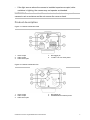
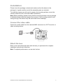
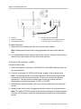
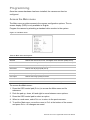
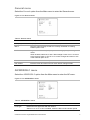
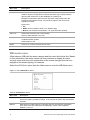
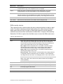
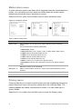
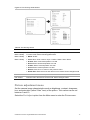
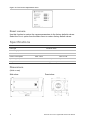
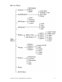
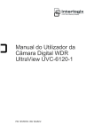
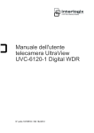
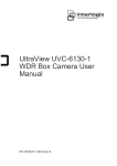
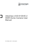
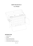
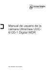
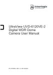
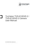
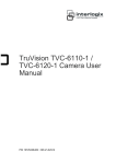
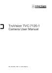
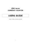
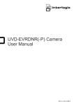
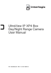
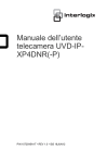
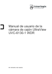
UltraView UVC-6120-1
Digital WDR Camera User
Manual
P/N 1072551B-EN • ISS 18JUN12
Copyright
Trademarks and
patents
© 2012 UTC Fire & Security. All rights reserved.
The TruVision and Interlogix names and logo are trademarks of
UTC Fire & Security.
Other trade names used in this document may be trademarks or
registered trademarks of the manufacturers or vendors of the
respective products.
Manufacturer
UTC Fire & Security Americas Corporation, Inc.
2955 Red Hill Avenue, Costa Mesa, CA 92626-5923, USA
Authorized EU manufacturing representative:
UTC Fire & Security B.V.
Kelvinstraat 7, 6003 DH Weert, The Netherlands
Certification
N4131
FCC compliance
Class A: This equipment has been tested and found to comply with
the limits for a Class A digital device, pursuant to part 15 of the FCC
Rules. These limits are designed to provide reasonable protection
against harmful interference when the equipment is operated in a
commercial environment. This equipment generates, uses, and can
radiate radio frequency energy and, if not installed and used in
accordance with the instruction manual, may cause harmful
interference to radio communications. Operation of this equipment in
a residential area is likely to cause harmful interference in which
case the user will be required to correct the interference at his own
expense.
ACMA compliance
Notice! This is a Class A product. In a domestic environment this
product may cause radio interference in which case the user may be
required to take adequate measures.
European Union
directives
12004/108/EC (EMC directive): Hereby, UTC Fire & Security
declares that this device is in compliance or with the essential
requirements and other relevant provisions of Directive 2004/108/EC
2002/96/EC (WEEE directive): Products marked with this symbol
cannot be disposed of as unsorted municipal waste in the European
Union. For proper recycling, return this product to your local supplier
upon the purchase of equivalent new equipment, or dispose of it at
designated collection points. For more information see:
www.recyclethis.info.
Contact information
For contact information, see www.utcfireandsecurity.com or
www.utcfssecurityproducts.eu.
Content
Product overview 2
Package Contents 2
Features 2
User guidelines 2
Product description 3
OSD control pad 4
Installation 5
Connect the video cable 5
Attach the lens 5
Connect the power cable 6
Programming 8
Access the Main menu 8
General menu 9
AE/WDR/BLC menu 9
WB mode menu 10
D/N mode menu 11
Motion alarm menu 12
Privacy menu 12
Picture adjustment menu 13
Reset camera 14
Specifications 14
Dimensions 14
Menu Map 15
UltraView UVC-6120-1 Digital WDR Camera User Manual
1
Product overview
The UVC-6120-1- XX color video camera uses a digital signal processor (DSP)
to process video signals. The video camera includes a microcontroller to provide
high-quality images with high-color reproduction and sharp pictures.
Package Contents
The package contains the following:
•
Box camera
•
Dual power terminal block with screw and anchor
•
Hex wrench
Features
The camera includes the following features:
•
Exview HAD II (hole accumulated diode) technology with 480,000 pixels
NTSC (570,000 PAL)
•
LSI (large scale integration) digital processors, producing 650 lines of
horizontal resolution
•
Smart digital control automatic BLC (backlight compensation)
•
Digital WDR (wide dynamic range)
•
Advanced auto exposure system for both fixed iris and auto iris lenses to
optimize the amount of light
•
Internal synchronization
•
Eight privacy mask areas to protect privacy concerns
•
Advanced OSD (onscreen display) control
•
Signal-to-noise ratio better than 52 dB
•
Long life and high reliability
•
Isolated switching power 12 VDC and 24 VAC
User guidelines
•
Program the camera settings as much as possible before mounting the
camera. Take appropriate safety precautions while completing programming
after installation.
•
Always use a 12 VDC or 24 VAC UL listed Class 2 power supply to power the
camera.
•
Do not use the camera over the temperature range specifications: -10°C to
+50°C (14°F to 122°F)
2
UltraView UVC-6120-1 Digital WDR Camera User Manual
•
If the light source where the camera is installed experiences rapid, widevariations in lighting, the camera may not operate as intended.
WARNING: To reduce the risk of fire or electronic shock, do not expose the
camera to rain or moisture and do not remove the cover or back.
Product description
Figure 1: Camera UVC-6120-1-P/N
1. Video output
2. Audio output
3. OSD control pad
4. D/N trigger pin
5. 12 VDC / 24 VAC dual power
Figure 2: Camera UVC-6120-1-P2
1. Video output
2. Audio output
3. OSD control pad
UltraView UVC-6120-1 Digital WDR Camera User Manual
4. D/N trigger pin
5. AC96V/AC240 universal power
3
OSD control pad
The on-screen display (OSD) control pad (see Figure 1) lets you manually control
the camera functions. Table 1 below lists the OSD control pad functions and
describes their use.
Table 1 Using the OSD control pad
Pad direction
Description
Up
Moves the cursor upward to select an item
Left
Moves the cursor left to select or adjust the parameters of the selected
item.
Right
Moves the cursor to the right to select or adjust the parameters of the
selected item.
Down
Moves the cursor downward to select an item.
Enter
Press the center of the control pad to display the Main menu. If the
selected item has its own menu, press the pad to enter a submenu.
4
UltraView UVC-6120-1 Digital WDR Camera User Manual
Installation
Please check the package contents and make sure that the device in the
package is in good condition and all the assembly parts are included.
To install the camera you will need to prepare the mounting surface, mount the
camera, attach the lens, and make cable connections,
Note: Before installing, please ensure that the mounting surface is strong enough
to withstand three times the weight of the camera. If the mounting surface is not
strong enough, the camera may fall and cause serious damage.
Connect the video cable
Connect a coaxial cable from the camera’s BNC connector to a CCTV monitor or
video recording device.
Attach the lens
Refer to the instructions that came with the lens you purchased for complete
installation instructions of that lens.
Note: For optimal performance, use an auto iris lens.
UltraView UVC-6120-1 Digital WDR Camera User Manual
5
Figure 3: Attaching the lens
1. Camera
2. Autoiris lens plug
3. Lens (autoiris shown)
4. DC type autoiris lens leads
A. Damping coil (+); B. Damping coil (-);
C Driving coil (+); D Driving coil (-)
To attach the lens:
1. Screw the lens clockwise onto the lens mount of the camera.
Note: Please prevent dust from entering between the lens mount and the
lens.
2. For optimal performance, please use an auto iris lens. Plug the auto-iris drive
cable to the 4-pin interface on the side of the camera.
Connect the power cable
For UVC-6120-1-P/N
1. With a screwdriver, loosen the ~AC24V/DC12V and GND terminal screws on
the terminal block.
2. Connect a universal 12 VDC/24 VAC power supply to the terminal block.
Note: The terminal block is not polarity sensitive. Either power lead can be
connected to either terminal connector. There is no need for an isolated
ground wire. The two power terminals can accept any polarity and any
combination of power that equals 12 VDC or 24 VDC.
3. Retighten the terminal screws until snug, ensuring that the power leads are
secure.
4. Supply power to the unit by plugging the power supply into a proper source.
Note: The power LED illuminates to show that the camera is receiving power.
If it does not illuminate, check the terminal block connections and the power
source.
6
UltraView UVC-6120-1 Digital WDR Camera User Manual
For UVC-6120-1-P2
Connect the power cable of a high voltage camera to either a 230 VAC or a 120
VAC power supply outlet.
UltraView UVC-6120-1 Digital WDR Camera User Manual
7
Programming
Once the camera hardware has been installed, the camera can then be
configured.
Access the Main menu
The Main menu provides access to the camera configuration options. The onscreen display (OSD) is only available in English.
Program the camera by attaching a standard video monitor to the system.
Figure 4: The Main menu
Table 2: Main menu description
Menu item
Description
General
Defines the camera ID, mirror, and digital noise reduction (DNR) set up.
AE/WDR/BLC
Defines the lens type as well as the WDR/BLC, AGC, and flicker set up.
WB mode
Defines the white balance (WB) set up.
D/N mode
Defines the day/night (D/N) set up.
Motion
Defines the motion detection set up.
Privacy
Defines privacy mask set up.
Pict adjust
Defines the image quality functions.
Reset camera
Resets the camera to factory default settings.
Exit & save
Exits the menu and returns to live mode. Saves changes made.
To access the Main menu:
1. Press the OSD control pad (Enter) to access the Main menu and its
submenus.
2. Push the pad up, down, left and right to move between menu options.
3. Press the OSD control pad to select an option.
4. When in a sub menu, select Return to return to the previous menu.
5. To exit the Main menu, move the cursor to Exit at the bottom of the screen
and press Enter. All changes are saved.
8
UltraView UVC-6120-1 Digital WDR Camera User Manual
General menu
Select the General option from the Main menu to enter the General menu.
Figure 5: The General menu
Table 3: General menu
Parameter
Description
ID display
Displays the camera ID on screen. Default option is Off.
Mirror
Flips the camera image so that it is correctly orientated for viewing.
Default option is Off.
DNR
Digital noise reduction (DNR) improves the image quality in low light
levels.
When enabled, select the Y and C filter strength: Press Return to return
to the previous menu or Exit & Save to save changes and return to live
mode. Default option is On.
Return
Press Enter to return to the previous menu.
Exit & Save
Exits the menu and returns to live mode. Saves changes made.
AE/WDR/BLC menu
Select the AE/WDR/BLC option from the Main menu to enter the AE menu.
Figure 6: The AE/WDR/BLC menu
Table 4: AE/WDR/BLC menu
Menu item
Description
Lens type
Defines the lens type used with the camera.
Select Fixed or DC. If DC is enabled, select the DC level and shutter speed
UltraView UVC-6120-1 Digital WDR Camera User Manual
9
Menu item
Description
from the options shown.
WDR/BLC set
Wide dynamic range (WDR) allows you to see details of objects in shadows or
details of objects in bright areas of frames that have high contrast between
light and dark areas such as the headlights of a passing car.
Backlight compensation (BLC) function improves image quality when the
background illumination is high. It prevents the object in the center from
appearing too dark.
Options are:
• Off
• WDR: Set the luminance level ( Low, Middle, High)
• BLC fix: set the BLC level (between 1 to 30) and the BLC window.
AGC max
Defines the automatic gain control (AGM).
Select a value between 0 and 160.
Flicker
This feature to prevent the strobing effect under certain lighting
conditions/shutter speeds.
Default option is Off.
Return
Press Enter to return to the previous menu.
Exit & Save
Exits the menu and returns to live mode. Saves changes made.
WB mode menu
White balance (WB) tells the dome camera what the color white looks like. Based
on this information, the dome camera will then continue to display all colors
correctly even when the color temperature of the scene changes such as from
daylight to fluorescent lighting, for example.
Select the W/B Mode option from the Main menu to enter the WB Mode menu.
Figure 7: The AE/WDR/BLC menu
Table 5: AE/WDR/BLC menu
Menu item
Description
ATW
The auto track white balance (ATW) function automatically adjusts the WB in real
time as the lighting conditions change. It can be used for both indoor and outdoor
locations.
Manual
Manually fix the white balance by adjusting the blue and red gain parameters.
Only use this function when there is steady light. Values can be adjusted
between -5 and +5.
10
UltraView UVC-6120-1 Digital WDR Camera User Manual
Menu item
Description
Outdoor
Select this option to optimize the WB for outdoor sunlit applications. The ATW
compensates for high color temperature such as daylight.
Indoor
Select this option to optimize the WB for indoor applications. The ATW
compensates for low color temperature such as incandescent lighting.
Anti CR
The anti-color rolling mode function minimizes the color changes over long
periods caused by very small differences between the flicker frequency of noninverter fluorescent lights and the drive frequency of the image sensor devices.
Return
Press Enter to return to the previous menu.
Exit & Save
Exits the menu and returns to live mode. Saves changes made.
D/N mode menu
This camera function controls when the dome camera switches to day or night
mode. The dome camera produces high-quality color video during the day or
when light levels are high. At night or when light levels are low the camera
switches monochrome and removes the infrared filter to improve IR sensitivity.
Select the D/N Mode option from the Main menu to enter the D/N mode menu.
Table 6: D/N mode menu
Menu item
Description
Auto
When set to Auto Day/Night mode, the camera produces high-quality color
video during the day or when light levels are high. It then switches to
monochrome and removes the infrared filter to improve IR sensitivity at
night or when light levels are low. Set following parameters:
Day→Night: Set the threshold level on how dark it should be before
switching from Day to Night mode. Lower (Higher) value makes the
camera switched from Day to Night at lower (higher) illumination
Night→Day: Set the threshold level on how light it should be before
switching from Night to Day mode.
Delay seconds: This is the time in seconds before Day↔Night switches.
A long delay response would be used, for example, to avoid switching
from Night to Day mode when car headlights pass in front of the camera.
CAUTION: If there is a minimal difference between the Day→Night and
Night→Day values, then camera may switch between Day and Night
mode repeatedly.
Day
Manually select Day mode only. The camera can only be in Day mode.
Night
Manually select Night mode only. The camera can only be in Night mode.
Ext
Externally triggered D/N switch.
Return
Press Enter to return to the previous menu.
Exit & Save
Exits the menu and returns to live mode. Saves changes made.
UltraView UVC-6120-1 Digital WDR Camera User Manual
11
Motion alarm menu
A motion detection alarm is an alarm that is triggered when the camera detects a
motion. You can define up to four areas on screen where the motion can be
detected as well as the level of sensitivity to motion.
Select the Motion option from the Main menu to enter the Motion menu.
Figure 8: The Motion menus
Table 7: Motion alarm menu
Menu item
Description
Motion Detec.
When enabled, you can set up four motion detection areas (Labels) on
screen.
For each label set the following parameters:
• Label frame: On/Off
• Label color: Blue / Pink / Yellow / Cyan / Coffee / White / Red / Green
• H Start: Start of horizontal position 0 to 23
• H End: End of horizontal position 0 to 23
• V Start: Start of vertical position 0 to 23
• V End: End of vertical position 0 to 23
• Return: Press Enter to return to the previous menu
• Exit & Save: Exits the menu and returns to live mode. Saves changes
made
Defines the motion or face threshold.
MD Detect. Th
Select a value between 0 and 127. A lower value means detection is more
sensitive.
Return
Press Enter to return to the previous menu.
Exit & Save
Exits the menu and returns to live mode. Saves changes made.
Privacy menu
Privacy masks let you conceal sensitive areas (such as neighboring windows) to
protect them from view on the monitor screen and in the recorded video. The
masking appears as a blank colored area on screen. You can create up to 4
privacy masks.
Select the Privacy option from the Main menu to enter the Privacy menu.
12
UltraView UVC-6120-1 Digital WDR Camera User Manual
Figure 9: The Privacy mask menus
Table 8: The Privacy menu
Menu item
Description
Mask 1 Setup
When enabled, you can set up four privacy mask areas on screen.
Mask 2 Setup
For each mask set the following parameters:
Mask 3 Setup
• Mask: On/Off
Mask 4 Setup
• Color: Blue / Pink / Yellow / Cyan / Coffee / White / Red / Green
• H Start: Start of horizontal position 0 to 500
• H End: End of horizontal position 0 to 500
• V Start: Start of vertical position 0 to 280
• V End: End of vertical position 0 to 280
• Return: Press Enter to return to the previous menu
• Exit & Save: Exits the menu and returns to live mode. Saves changes made
Return
Press Enter to return to the previous menu.
Exit & Save
Exits the menu and returns to live mode. Saves changes made.
Picture adjustment menu
Set the camera image characteristics such as brightness, contrast, sharpness,
hue, and saturation (called “Gain” here) of the picture. Their values can be set
between 0 and 10.
Select the Pict Adjust option from the Main menu to enter the Picture menu.
UltraView UVC-6120-1 Digital WDR Camera User Manual
13
Figure 10: The Picture adjustment menu
Reset camera
Use this function to restore the camera parameters to the factory defaults values.
Select the Reset option from the Main menu to restore factory default values.
Specifications
Model
UVC-6120-1-P / UVC-6120-1-N
Lens type
Power supply
Current
Power consumption
Operating temperature
Weight
UVC-6120-1-P2
C/CS-DC drive
24 VAC / 12 VDC
96 to 240 VAC
300 mA
50 mA
Max. 3.6 W
Max. 4.8 W
-10 to +50 °C (14 to 122 °F)
390 g (0.85 lb.)
Dimensions
(Units = mm)
Side view :
14
Front view :
UltraView UVC-6120-1 Digital WDR Camera User Manual
Menu Map
UltraView UVC-6120-1 Digital WDR Camera User Manual
15