1
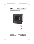
3101
3101
High/Low Limit Controller
High/Low Limit Controller
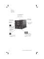
Issue Date
November 2007
Operator’s Manual
0037-75253
Issue Date
November 2007
Operator’s Manual
0037-75253
Table of Contents
Sections
Section
1
Topic
Page
Getting Started ................................................................. 1
2
Installation ........................................................................ 3
3
Operation ......................................................................... 1
4
Controller Setup PAGEs ................................................. 23
5
Limit Control Operation .................................................. 29
6
Alarms ............................................................................ 35
7
Digital Event Input .......................................................... 41
8
Analog Output Option .................................................... 43
9
Digital Communications ................................................. 45
10
Calibration ...................................................................... 51
11
Specifications ................................................................. 57
12
Troubleshooting .............................................................. 61
13
Warranty and Return ...................................................... 63
Appendices
I
PAGE/MENU Tables ....................................................... 65
Menu Index
Index
....................................................................................... 73
Chromalox 3101 Operator's Manual
i
Illustrations
Fig.
Topic
1.1
Model Identification................................................................ 2
2.1
2.2
2.3
Sensor Selection Dip Switch Settings ................................... 3
Mounting Dimensions ............................................................ 5
Mounting Diagram.................................................................. 5
2.4
2.5
2.6
Wiring Terminal Identification ................................................. 7
Thermocouple Connections ................................................... 8
3-Wire RTD Connections ....................................................... 9
2.7
2.8
2.9
2-Wire Connections ............................................................... 9
Current Input Wiring (Self-powered) ...................................... 9
Voltage Input Wiring (Self-powered) .................................... 10
2.10
2.11
2.12
Current Input Wiring (Loop-powered by controller) ............. 10
Momentary Contact Pushbutton.......................................... 10
Relay Output Connections ................................................... 11
2.13
2.14
2.15
Alarm #1 Relay Output ......................................................... 12
Alarm #2 Output ................................................................... 12
100-240 Vac Instrument Power Conn. (3101-11**0) ............ 13
3.1
3.2
3.3
Front Panel Identification ..................................................... 16
PAGE/MENU Setup Structure .............................................. 17
Sample of PAGE/MENU Table ............................................. 19
3.4
3.5
Security Levels and PAGE/MENU Contents ........................ 20
Security Codes and View/Adjust Levels .............................. 21
ii
Page
Chromalox 3101 Operator's Manual
Illustrations
Figure
Topic
Page
5.1
Process Variable Profile—High Limit Control ....................... 31
6.1
Low Alarm Inhibit ................................................................. 36
8.1
8.2
Analog Output Signal ........................................................... 43
Process Output Wiring ......................................................... 44
9.1
9.2
9.3
RS422/RS485 Communications Switches........................... 46
RS232 Wiring Connections .................................................. 46
RS232 Connector Pin Designations..................................... 47
9.4
9.5
9.6
9.7
RS485 Wiring Connections (4-wire) ..................................... 47
RS422 Connector Pin Designations..................................... 48
RS485 Wiring Connections (2-wire) ..................................... 48
RS485 Connector Pin Designations..................................... 48
Chromalox 3101 Operator's Manual
iii
iv
Chromalox 3101 Operator's Manual
Section 1
Getting Started
The Chromalox 3101 is a compact 1/4 DIN programmable high/low limit controller with two independent
alarms. While designed to be low-cost, the 3101 has
many features of high-end limit controllers:
• Universal Sensor Input
• Switching Power Supply allows universal AC
voltage input (100 to 230 Vac)
• U. L. and U. L. (Canadian) Listed
as an Overtemperature Controller
• FM High/Low Limit Controller
• High Impact Plastic Bezel and Housing
• One high/low limit output and two independent
alarm outputs
• Time over/under setpoint display
• Max/Min process variable display
• One programmable Digital Input
• Isolated Serial Communications (optional)
• Analog Process Output (optional)
• Security protection
• 32°F to 149°F Operating Temperature
• ±0.2% Accuracy Specification
• VIEW DATA key on front panel for a quick access to Display Page
• Power Down Recovery feature retains limit and
alarm status when power is restored
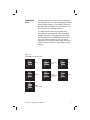
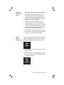
Model Identification
Before installation, please identify your controller model number. The
model number is written on the tag on the side of the housing.
Figure 1.1 Model Identification
Model Temperature Controller
3101
Microprocessor-based 1/4 DIN Programmable High/Low Limit Controller.
Universal Sensor Input accepts Thermocouple, RTD, Current or Voltage Inputs.
One Digital Input and One Alarm Output.
Code
1
Limit Output #1
Relay—Form C Contact, 5A @ 120 or 230 Vac
Code Alarm #1 Output
1
Relay—Form C Contact, 5A @ 120 or 230 Vac
Code Analog Process Output Option
0
1
None
Field selectable 4-20mA or 1-5 Vdc
Code Digital Comm. and Alarm #2 Options
0
1
2
None
RS422/485 Digital Communications and
Alarm #2 Relay—Form C contact, 5A @
120 or 230 Vac
RS232 Digital Communications and
Alarm #2 Relay—Form C Contact, 5A @
120 or 230 Vac
Code Power Supply
0
3101 -
1
1
1
2
0
100 - 230 Vac
Typical Model Number
Section 2
Installation
Inspection
and
Unpacking
On receipt of your 3101 controller, immediately
make note of any visible damage to the shipment packaging and record this damage on the
shipping documents. Unpack the controller and
carefully inspect it for obvious damage due to
shipment. If any damage has occurred, YOU must
file a claim with the transporter, as they will not
accept a claim from the shipper.
If the controller will not be immediately installed
and placed into operation, it should be stored in
a cool, dry environment in its original protective
packaging until time for installation and operation.
Temperature extremes and excessive moisture
can damage the instrument.
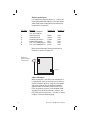
Switch
Settings
The 3101 has up to seven (7) hardware switches
located on the bottom of the controller. The
switches are accessible through cutouts in the
controller housing and do not require that you
remove the controller from its housing to access
the switches.
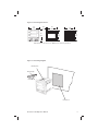
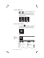
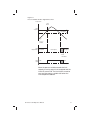
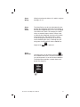
Figure 2.1 identifies the switches. Instructions for
switch settings are given in the corresponding
sections of the manual.
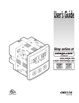
Figure 2.1
Sensor Selection
Dip Switch
Settings
Switches #1 and #2
Digital Communications
RS422/RS485
Controller Bottom Surface
Switches #1, #2 and #3
Sensor Input
Chromalox 3101 Operator's Manual
Switch #4
(not used)
Switch #5
Analog Output
Signal
3
Sensor
Selection
Switches
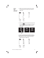
Sensor selection requires that you:
1.
2.
Set the sensor switches for the correct sensor type.
Program the input sensor type in sensor
selection setup on the INPT Page (see page
36).
It is much easier to set the sensor input switches before you mount and wire the controller.
To set the sensor switches:
1.
2.
Locate the sensor switches — #1, #2 and
#3 — on the bottom of the controller, as
shown in Figure 2.1 on the previous page.
Place the switches in the appropriate Up or
Down position for your input type:
Input Type
T/C
RTD
4-20mA
1-5 Vdc
Mounting
Switch #
1
Up
Down
Up
Up
2
Up
Up
Down
Up
3
Up
Up
Down
Down
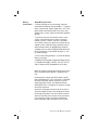
Figure 2.2, on the following page, shows the
mounting dimensions for the controller:
1. Cut out the square “panel cutout” mounting
hole and install the unit as shown in Figure
2.3.
2. Place the controller through the square
panel cutout and replace the mounting clip.
3. Tighten the mounting clip screw (do not
overtighten) to secure the controller firmly
against the mounting surface.
4
Chromalox 3101 Operator's Manual
Figure 2.2 Mounting Dimensions
3.8
(96)
0.8
(19)
3.8
(96)
4.0
(102)
3.6
(92)
3.6
(92)
3.5
(90)
Panel Cutout
Measurements are shown in inches. Millimeters are shown in parentheses.
Figure 2.3 Mounting Diagram
Mounting Hole
Mounting Clip
Mounting Tab
Panel Cutout
Chromalox 3101 Operator's Manual
5
Wiring
Instructions
Good Wiring Practices
1. When planning the system wiring, separate
wiring into functionally similar bundles - i.e. power
leads, sensor leads, output signal lines, etc. If the
power leads and sensor leads must cross, they
should cross at a 90° angle to each other (perpendicular).
2. Locate all sources of electrical noise in your
system, and separate these sources from the
control systems—motors, contacts, solenoids,
etc. Electrical noise can affect the function of any
control system. When driving a contactor coil or
other inductive load, an appropriately rated AC
snubber circuit is recommended (Chromalox Part.
No. 0149-01305), as described on page 11, “Relay Output Wiring.”
3. For sensor wiring practices, see Sensor Wiring
Notes, next page.
4. Additional information on good wiring practices
is available from IEEE, 345 East 47th St., NY, NY
10017. Request IEEE Standard No. 518-1982.
Make all electrical wiring connections to the back
of the controller before power is applied to the
unit.
All wiring must comply with local codes, regulations and ordinances. This instrument is intended
for panel mounting and the terminals must be
enclosed within a panel. Use National Electric
Code (NEC) Class 1 wiring for all terminals except
the sensor terminals.
Check the wiring decal on the side of the unit to
verify the model number. The wiring decal shows
the wiring terminations. All wires will be connected to the terminals on the back of the instrument
case. Specific wiring instructions for different
input and output types are given in this section.
6
Chromalox 3101 Operator's Manual
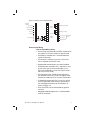
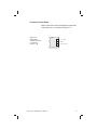
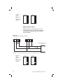
Figure 2.4 Wiring Terminal Identification
1
19
Common
2
20
+24 Vdc Output
3
21
Analog Output
4
22
Not Used
5
23
Common
6
24
7
25
Digital
Input
Sensor Input
8
26
9
27
RTD
10
11
Digital
Comm.
Limit Control Output
12
13
14
Not Used
Alarm #2
Output
Alarm #1 Output
15
16
100/240 Vac or
17
AC Common
18
Shield Ground
Instrument
Power
TC 4-20mA
Sensor Input Wiring
Sensor Input Wiring Notes:
• Sensor leads (thermocouple and RTD) should not be
run together in the same conduit as power wiring.
• Twisted pair, shielded wire is recommended for
sensor connections.
• False process readings can occur if the sensor
wire is exposed to electrical noise.
• Ungrounded thermocouples are recommended.
• If thermocouple extension wire is required, it must
be the same type as the thermocouple (i.e. if a
Type K thermocouple is used, then Type K extension wire must be used).
• Thermocouple wires should connect directly to
the controller terminals. Do not use copper crimp
terminals or solder terminals to make connections.
• If shielded thermocouple wire is used, the shield
must be grounded at one end only, preferably at
the shield ground terminal on the controller, as
shown in Figure 2.5.
• Three wire RTDs are recommended for greatest
accuracy.
• Standard shielded copper wire is recommended
for RTD extensions.
Chromalox 3101 Operator's Manual
7
Thermocouple Inputs
It is important to observe polarity (+, -) when connecting thermocouple leadwires. The table below
shows ANSI color coding for the thermocouples
used with this instrument.
T/C Type
B
J
K
E
T
R
S
Material
Plat, 30% Rhodium/
Plat, 6% Rhodium
Iron/Constantan
Chromel/Alumel
Chromel/Constantan
Copper/Constantan
Plat, 13% Rhodium/Plat
Plat, 10% Rhodium/Plat
Polarity (+)
Gray
Polarity (-)
Red
White
Yellow
Purple
Blue
Black
Black
Red
Red
Red
Red
Red
Red
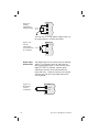
Make the thermocouple wiring connections to
terminals as shown in Figure 2.5.
Figure 2.5
Thermocouple
Connections
3101
+
8
-
9
18
Shield Gnd
3-Wire RTD Inputs
When making the 3-wire RTD input connection, it
is important to make the resistance of all three extension leadwires equal by using the same gauge
and same length of wire for optimum leadwire
compensation. Chromalox recommends 3-wire
RTDs for greatest accuracy, and standard shielded copper wire for RTD extensions. Make 3-wire
RTD connections to terminals 7, 8 and 9 as shown
in Figure 2.6 on the following page.
8
Chromalox 3101 Operator's Manual
Figure 2.6
3-Wire RTD
Connections
3101
7
8
18
9
Shield Grnd
2-Wire RTD Inputs
If using a 2-wire RTD input, use heavier gauge
leadwires to reduce leadwire resistance. Any
leadwire resistance adds directly to sensor
resistance, thus adding error to the process
temperature measurement. It is also necessary
to jumper terminals 8 and 9 on the instrument to
complete a 2-wire hookup.
Figure 2.7
2-Wire
Connections
3101
7
8
9
Current/Voltage Inputs
Figure 2.8
Current
Input Wiring
(Self-powered)
+
4-20mA
3101
7
8
9
Chromalox 3101 Operator's Manual
9
Figure 2.9
Voltage
Input Wiring
(Self-powered)
3101
+
7
1-5 Vdc
0-5 Vdc
8
9
The 3101 has a +24 Vdc power supply which can
be used to power a 4-20mA transmitter.
Figure 2.10
Current
Input Wiring
(Loop-powered
by controller)
+
3101
3 +24 Vdc
4-20mA
7
Digital Input
Connections
Figure 2.11
Momentary
Contact
Pushbutton
10
The digital input can be used to reset the latching
alarms—Limit Output, Alarm #1 and Alarm #2.
Setup for the digital input is shown on the Setup
page (SET PAGE). An external, normally open,
momentary contact can be connected to this
input (100 msec., minimum closure). Use isolated
switches only. Do not tie the Digital Input terminals to ground.
3101
1
+
2-
{ External
Input
Chromalox 3101 Operator's Manual
Output
Wiring
The 3101 is supplied with:
• 1 Relay Output for Limit Output Control
• 1 Relay Output for Alarm #1
As an option, it may also include:
• 1 Relay Output for Alarm #2
☛
Warning
Incorrect output wiring may cause system/process damage.
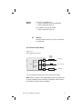
Limit Control Output Wiring
Figure 2.12
Relay Output Connections
Alarm
Indicator
Light
10
Normally
Closed
AC Neutral
MOV
Fuse*
11
Limit
3101
Normally
Open
120 or 230 Vac
MOV
12
Load
AC Neutral
*Fuse should be sized for the current of the Limit Output.
Note: Relay is shown in De-energized (fail safe) state (Power off
or alarm condition). Relay would be energized in normal operation (Power on and no alarm condition).
Chromalox 3101 Operator's Manual
11
Alarm #1
Output
The independent Alarm #1 relay output is connected as shown in Figure 2.13.
Figure 2.13
Alarm #1 Relay Output
3101
Normally
Closed
13
Load
AC Neutral
MOV
Fuse*
14
Normally
Open
120 or 230 Vac
MOV
15
Load
AC Neutral
* Fuse should be sized for the current Alarm #1 Output.
Alarm #2
Output
The Form C Relay Output is connected as shown
in Figure 2.14.
Figure 2.14
Alarm #2
Output
3101
25
Normally
Open
Load
AC Neutral
MOV
Fuse*
26
Alarm #2
Normally
Closed
120 or 230 Vac
MOV
27
Load
AC Neutral
* Fuse should be sized for the current of Alarm #2 Output.
12
Chromalox 3101 Operator's Manual
Instrument Power Wiring
Make 120/230 Vac instrument power connections
to terminals 16-18 as shown in Figure 2.15.
Figure 2.15
100-240 Vac
Instrument Power
Connections
(3101-11**0)
Chromalox 3101 Operator's Manual
3101
16
100 - 240 Vac
17
Neutral
18
Chassis Ground
13
14
Chromalox 3101 Operator's Manual
Section 3
Operation
Section
Contents
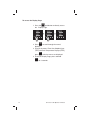
Pushbuttons and Indications
Security Codes and Levels
Controller Operation
Pushbuttons
and
Indications
Control programming is easily accomplished with
the front panel pushbuttons. The displays provide
a constant overview of the process. Figure 3.1, on
the next page, summarizes the functions of the
pushbuttons and displays.
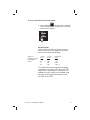
Normal Display Mode
At powerup, and when the controller is not being
programmed, the upper display shows the Process Value and the lower display shows the limit
setpoint.
The setpoint can be changed in the Normal Disand
pushbuttons,
play Mode using the
if the Security Level allows setpoint changes (see
page 20 for Security Levels).
150
➮
150
▲
▼
☛
RESET VIEW
DATA
150
200
RESET VIEW
DATA
▲
▼
Use ▲ and ▼ to
change setpoint in
Normal Display Mode.
Disable Lower Display
The lower display may be disabled for applications where it is desirable to have only the Process Variable displayed in the upper display. See
SET PAGE, menu LDSP, page 24.
Chromalox 3101 Operator's Manual
15
Figure 3.1
Front Panel
Identification
• Process Variable Display in
Normal Display Mode
• Alphanumeric Menu
display in Setup Mode
LED indicates Limit
Control Output ON
LEDs indicate
Alarms #1 or #2
Output ON
LEDs indicate °F
or °C selected for
Process Variable
Limit Setpoint Display
• May be disabled
on SET PAGE
RESET
Pushbutton
• Reset Latching Alarms
• Resets Limit Alarm
• Hold for more than
3 seconds to enter or
exit Setup Mode
• Scrolls through
MENUs in
Setup Mode
VIEW
DATA
Pushbutton
• To access Display Page
• To scroll through Display
Page Menus
16
• In Normal Display Mode,
pushbuttons adjust Setpoint.
• In Setup Mode, pushbuttons
increase/decrease MENU
values.
Chromalox 3101 Operator's Manual
PAGE/MENU
Setup
All control parameters, selections and calibration
procedures for the 3101 are accomplished through
simple MENU selections. These MENU selections
are organized into PAGES. On each PAGE you will
find a specific set of related functions.
This organization allows you to go directly to
the parameter to be adjusted, without stepping
through a long series of unrelated entries. Figure
3.2 illustrates the 3101 PAGE/MENU setup structure. Only pages that apply to your unit will be
displayed (i.e. if you do not have Digital Communications or Alarm #2 options, these pages will not
appear).
Figure 3.2
PAGE/MENU Setup Structure
DISP
SET
INPT
Display
PAGE
RESET VIEW
DATA
▲
Limit Control
Setup
PAGE
▼
RESET VIEW
DATA
AL2
▲
▼
RESET VIEW
DATA
▲
RESET VIEW
DATA
SCAL
PAGE
▼
RESET VIEW
DATA
▲
▲
▼
AL1
Alarm #2
PAGE
Input
PAGE
▼
Custom
Input/Output
Scaling
Alarm #1
PAGE
RESET VIEW
DATA
▲
▼
DIG
Digital
Communications
PAGE
RESET VIEW
DATA
▲
▼
Chromalox 3101 Operator's Manual
17
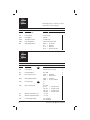
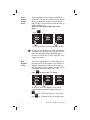
Accessing a MENU is accomplished by entering the Setup Mode, then selecting a PAGE and
MENU.
To enter Setup Mode:
RESET
Hold down the
than 3 seconds.
250
☛
▲
LOCH
➮
250
RESET VIEW
DATA
pushbutton for longer
▼
458
▲
RESET VIEW
DATA
Hold for at least
3 seconds.
▼
Setup Mode entered.
To select a PAGE:
Press and hold the Reset pushbutton, while
or
Pushbutton. The
pressing the
upper display will increment (or decrement)
through the PAGEs, and PAGE will be displayed
in the lower display.
Hold
Press ▲ or ▼
➮
PAGE
RESET VIEW
DATA
▲
▼
Press ▲ or ▼
Hold
➮
PAGE
RESET VIEW
DATA
☛
☛
☛
☛
▼
☛
▲
INPT
▲
▼
AL 1
PAGE
RESET VIEW
DATA
▲
▼
☛
➮
250
RESET VIEW
DATA
SET
☛
SP
Press ▲ or ▼
Hold
To select a MENU:
RESET
to
After reaching the correct PAGE, press
move through the MENUs. The alpha cue for the
MENU will appear on the upper display, and the
current value will appear in the lower display.
☛
18
▲
▼
➮
50
☛
➮
PAGE
RESET VIEW
DATA
ALO1
RESET VIEW
DATA
▲
▼
AHI1
250
☛
AL 1
RESET VIEW
DATA
▲
▼
Chromalox 3101 Operator's Manual
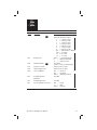
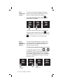
To change a MENU value:
After the MENU is selected and displayed, use the
and
pushbuttons to change the value.
For large adjustments (for example, 50 to 100),
hold the pushbutton pressed and the display will
change more quickly.
ALO1
➮
▲
1.5
☛
☛
1.0
RESET VIEW
DATA
ALO1
▼
RESET VIEW
DATA
▲
▼
To return to Operating Mode:
RESET
Press and hold
for more than 3 seconds. The
controller will automatically return to operating
mode after 10 minutes of no pushbutton activity.
99
☛
99
RESET VIEW
DATA
▲
▼
Hold for at least
3 seconds.
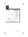
Figure 3.3
Sample of
PAGE/MENU
Table
SET
P A GE
RESET VIEW
DATA
▲
▼
SE
T Page
SET
MENU
Description
Available Settings
LO C
H
CH
Security Lock
0 to 9999
A
L SP
Limit Setpoint
Instrument Sensor Span
C
DB
Limit Dead Band
0 to 100 C
ENTI
Event Input Function
N ONE =
A LR =
Disabled
Alarm Reset
AO
UT
OUT
Analog Output Enable
N ONE =
P ROC =
Disabled
Process Variable
C ONT
Controller Type
HI
LO
Chromalox 3101 Operator's Manual
Security
D
19
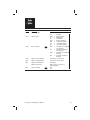
Security
Levels
Every parameter or selection in the 3101 controller’s setup PAGEs has an identifying MENU. Each
MENU is assigned one of four Security Levels,
A-D. In each level you may view certain MENUs,
and adjust certain MENUs. This allows you to
set the Security level that is appropriate for your
operating environment, prohibiting unauthorized access to or accidental changing of control
parameters.
Figure 3.4
Security Levels and PAGE/MENU Contents
Level
Code
Description
A
---
Display Page and Security Lock
B
123
Display Page and Security Lock
C
458
Settings for:
Limit Control
Alarms
Input
Digital Communications
D
736
Calibration
Digital Input, Analog Process Output
Entering the
Security Code
The Security Code is entered on the Setup
PAGE SET, at the MENU LOCK. This code determines which MENUs may be viewed and
adjusted.
The controller is set at Security Level C, when
you receive it from Chromalox.
20
Chromalox 3101 Operator's Manual
To access and enter the Security Code:
RESET
1. Press and hold
for more than 3 seconds
to enter Setup Mode. Security Lock is the first
menu that will appear.
LOCH
☛
458
RESET VIEW
DATA
▲
▼
Security Codes
Figure 3.5 lists the Security Codes for each of
the four Security Levels, along with the levels
that may be viewed and adjusted.
Figure 3.5
Security Codes &
View/Adjust
Levels
Security
Level
A
B
C
D
Security
Code
--123
458
736
View/Adjust
Level
A
A, B
A, B, C
A, B, C, D
If a number other than one of the three codes
listed above is entered at LOCK on the SET PAGE,
adjustment of all parameters is locked out. An
additional security number can be added using
the menu for User Selectable Security Code
(SET PAGE, menu CODE).
Chromalox 3101 Operator's Manual
21
To access the Display Page:
VIEW
DATA
1. Press the
pushbutton to directly access
the Display Page.
☛
100
RESET VIEW
DATA
▲
▼
VIEW
DATA
2. Press
displays.
➮
DISP
➮
PAGE
☛
100
RESET VIEW
DATA
▲
▼
PROC
100
RESET VIEW
DATA
▲
▼
to scroll through the menus/
3. To reset the menus Time Over Setpoint timer
(TOSP) and Peak Temperature Displays (PEAK),
RESET
press
while the menus are displayed.
4. To exit the Display Page, press and hold
RESET
for 3 seconds.
22
Chromalox 3101 Operator's Manual
Section 4
Controller Setup PAGEs
Section
Contents
Section
This section contains detailed information for the
following controller setup pages:
DISP: Display
SET:
Limit Control Setup
INPT: Input
SCAL: Custom Scaling
AL 1: Alarm #1
AL 2: Alarm #2
Setup PAGEs specific to certain functions are located in the section of this manual that addresses
that function specifically.
Page
Topic
Setup PAGE
6
35
Alarms
INPT, AL 1, AL 2
8
43
Analog Output Option
SET, INPT, SCAL
9
45
Digital Communications
DIG
More
Info
Throughout the following Setup PAGEs you will
find these symbols 40 . This indicates a section
of this User’s Manual where more specific information on a parameter/application/feature can be
found.
Chromalox 3101 Operator's Manual
23
DISP
PAGE
RESET VIEW
DATA
▲
The Display Page is for status only. None
of the settings can be changed.
▼
Display Page
MENU
Description
Displays
Security
PROC
Process Variable
Sensor Span
L SP
Limit Setpoint
Sensor Span
A
LOUT
Limit Output
ON/OFF
TOSP
Time Over Setpoint
0 TO 999.9 MIN
PEAH
Peak Temperature
Instrument Sensor Span
ALR
Alarm Output Status
NONE
AL 1
AL 2
AL12
=
=
=
=
No alarms
Alarm #1
Alarm #2
Alarm #1 and #2
SET
PAGE
RESET VIEW
DATA
▲
▼
SET Page
MENU
LOCH
Description
Security Lock
Available Settings
20
0 to 9999
Security
A
L SP
Limit Setpoint
Instrument Sensor Span
C
DB
Limit Dead Band
0 to 100
C
ENTI
Event Input Function
NONE =
ALR =
Disabled
Alarm Reset
AOUT
Analog Output Enable
NONE =
PROC =
Disabled
Process Variable
CONT
Controller Type
CODE
User Security Code
29
HI
LO
0 to 999
0-122
123-457
458-735
736-999
=
=
=
=
Security level A
Security level B
Security level C
Security level D
A LO
Ambient Temperature Low
-3 to 153
A HI
Ambient Temperature High
-3 to 153
LDSP
Lower Display Disable
ON = Enabled
OFF = Disabled
24
D
Chromalox 3101 Operator's Manual
INPT
PAGE
RESET VIEW
DATA
▲
▼
Input Page
MENU
Description
Available Settings
SENS
Sensor Type
UNIT
Display Units
COFF
Calibration Offset
SPLL
SPUL
Setpoint Low Limit
Setpoint Upper Limit
CALS
Sensor Calibration
INLO =
INHI
=
DONE =
AO 0
Analog Output Zero
Calibration
0 to 4095
AO S
Analog Output Span
0 to 4095
RECC
Factory Calibration Recovery
RDY =
---- =
DONE =
Security
4
Sensor Type selected here must
C
agree with dip switch settings.
J
= J Thermocouple
H
= K Thermocouple
T
= T Thermocouple
E
= E Thermocouple
R
= R Thermocouple
S
= S Thermocouple
B
= B Thermocouple
RTD = 100 Pt RTD (α = .00385)
4-20 = 4 to 20mA
0-5 = 0 to 5 Vdc
1-5 = 1 to 5 Vdc
NONE = none (analog inputs)
°F
= Degrees Fahrenheit
°C
= Degrees Celsius
56
0 to ±100°F
(±6.25% of span for analog inputs)
Instrument Sensor Span
Instrument Sensor Span
Chromalox 3101 Operator's Manual
Input low
Input high
Calibration finished
D
Ready
Wait
Finished
25
SCAL
PAGE
RESET VIEW
DATA
▲
This PAGE appears only when Analog
Input is selected, Remote SP is enabled,
or Analog Output is enabled on SET PAGE.
▼
Custom Scaling Page
MENU
Description
Available Settings
DP
Analog Input Decimal Pts.
9
0
1
2
3
AINL
Analog Process Input Low
9
-500 to 5000
AINH
Analog Process Input High
9
-500 to 5000
AOTL
Analog Process Output Low 44
Instrument Sensor Span
AOTH
Analog Process Output High 44
Instrument Sensor Span
=
=
=
=
Security
none
123.4
12.34
1.234
C
AL 1
PAGE
RESET VIEW
DATA
▲
▼
Alarm #1 Page
MENU
Description
Available Settings
Security
EN 1
Alarm 1 Enable
OFF
ON
=
=
Disabled
Enabled
C
TYP1
Alarm 1 Type
NONE
HI
LO
HILO
PDE
-DE
DE
=
=
=
=
=
=
=
Disabled (off)
High Alarm
Low Alarm
High-Low Alarm
Plus Deviation Alarm
Minus Deviation Alm
Plus/Minus Dev Alm
RLY1
Alarm 1 Relay
NDE
=
NE
=
NDEL
=
NEL
=
normally de-energized
non-latching
normally energized
non-latching
normally de-energized
latching
normally energized
latching
12
ALO1
Alarm 1 Low Setpoint
Instrument Sensor Span
AHI1
Alarm 1 High Setpoint
Instrument Sensor Span
DB1
Output 1 Dead Band
(Alarm Hysteresis)
0 to 100°F
(.00 to 6.25% of span for
analog inputs)
INH1
Alarm 1 Inhibit
26
36
OFF
ON
Chromalox 3101 Operator's Manual
AL 2
PAGE
RESET VIEW
DATA
▲
▼
Alarm #2 Page
MENU
Description
Available Settings
Security
EN 2
Alarm 2 Enable
OFF
ON
=
=
Disabled
Enabled
C
TYP2
Alarm 2 Type
NONE
HI
LO
HILO
PDE
-DE
DE
=
=
=
=
=
=
=
Disabled (off)
High Alarm
Low Alarm
High-Low Alarm
Plus Deviation Alarm
Minus Deviation Alm
Plus/Minus Dev Alm
RLY2
Alarm 2 Relay
NDE
=
NE
=
NDEL
=
NEL
=
normally de-energized
non-latching
normally energized
non-latching
normally de-energized
latching
normally energized
latching
12
ALO2
Alarm 2 Low Setpoint
Instrument Sensor Span
AHI2
Alarm 2 High Setpoint
Instrument Sensor Span
DB2
Output 2 Dead Band
(Alarm Hysteresis)
0 to 100°F
(.00 to 6.25% of span for
analog inputs)
INH2
Alarm 2 Inhibit
Chromalox 3101 Operator's Manual
36
OFF
ON
27
28
Chromalox 3101 Operator's Manual
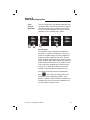
Section 5
Limit Control Operation
Limit
Control
Operation
The 3101 High/Low Limit Controller provides control output and visual indication when the process
variable exceeds the limit setpoint. The controller can be setup to operate as a high or low limit
controller at the “controller type” menu:
➮
99
▼
☛
☛
▲
➮
PAGE
☛
RESET VIEW
DATA
SET
RESET VIEW
DATA
▲
▼
CONT
➮
HI
☛
100
RESET VIEW
DATA
▲
▼
CONT
LO
RESET VIEW
DATA
▲
▼
On Powerup:
The controller status on powerup depends on
the process variable. If the process value (PV) is
within the setpoint range (i.e. below setpoint for
high limit, above setpoint for low limit), the controller will begin normal operation. If the PV is out
of the setpoint range (above setpoint for high limit,
below setpoint for low limit), the controller will be
in the limit alarm condition and cannot be reset
until the PV is within the setpoint range or the
setpoint is adjusted (above or below the PV).
To reset the limit output for normal operation,
RESET
press
. This will put the output relay in the
energized, normal operating condition. If the
process variable is above (or below) setpoint, the
controller will remain in the alarm condition and
the limit output cannot be reset.
Chromalox 3101 Operator's Manual
29
Limit
Control
Operation
Normal Operating Condition (no Limit Alarm):
Limit Output Relay: Energized
LIMIT LED:
Off
(continued)
Limit Alarm Condition:
Limit Output Relay: De-Energized
LIMIT LED:
ON
If the controller type is set as a high limit controller, the output is activated when the process
variable exceeds the setpoint. If set as a low
limit controller, the output is activated when the
process variable drops below the setpoint (see
Figure 5.1 on the following page).
Power Down Recovery:
In the event of a power failure, the 3101 will retain the current status of the Limit Alarm, record
the Time Over Setpoint (TOSP) and Peak Temperature value (PEAK). The controller will return
to this status when power is restored. If a limit
alarm occurred and power was interrupted, the
controller will restart in the Limit Alarm condition
when power is reapplied.
30
Chromalox 3101 Operator's Manual
Figure 5.1
Process Variable Profile—High Limit Control
Temperature
Limit
Alarm
Limit
Setpoint
→
Limit
Deadband
Process
Variable
Energized
Deenergized
Energized
→
Limit
Output Relay
Reset
Limit Alarm
Limit
LED
OFF
ON
OFF
When the process variable exceeds the limit
setpoint, the relay output is de-energized and the
Limit LED comes ON. The Limit Alarm cannot be
reset until the process variable falls below the
Limit Setpoint Deadband.
Chromalox 3101 Operator's Manual
31
Limit
Control
Output
Reset
To acknowledge the Limit Output and reset the
Output/LED, the process variable must be outside
of the limit deadband setting. If the limit condition still exists, the limit output cannot be reset (as
shown in Figure 5.1).
Reset the Limit Output/LED in one of two
ways:
RESET
1. Press
.
DISP
▲
➮
▼
➮
ON
RESET VIEW
DATA
▲
▼
LOUT
OFF
RESET VIEW
DATA
☛
☛
PAGE
RESET VIEW
DATA
LOUT
▲
▼
2. Press the Remote Alarm Acknowledge Switch.
41
Over
Setpoint
Timer
An external switching device can be connected to
the digital event terminals and used as a Remote
Alarm Acknowledge Switch. The digital input
function is setup on the SET PAGE, menu ENTI. See
page 41 for details.
The 3101 is equipped with a timer to register the
total process time over setpoint. This internal timer begins recording the total time of the process
over (or under) the limit setpoint. The time may be
reviewed on the Display page, menu TOSP.
Press
VIEW
DATA
to access the TOSP menu:
DISP
➮
▲
▼
➮
8.8
RESET VIEW
DATA
☛
☛
PAGE
RESET VIEW
DATA
TOSP
▲
▼
Timer over
setpoint = 8.8
TOSP
0.0
RESET VIEW
DATA
▲
▼
Timer Reset
To reset the Time Over Setpoint Timer the PV
must be within the normal setpoint limit. Press
RESET
to set the TOSP setting to “0.0”. Press and
RESET
hold
32
for 3 seconds to exit the Display Page.
Chromalox 3101 Operator's Manual
Peak
Temperature
Display
The 3101 also records and displays the peak
(minimum or maximum) temperature when the
process variable exceeds the setpoint.
To see the PEAK temperature, press
access the PEAK menu:
DISP
➮
☛
PAGE
▲
▼
▲
▼
60
RESET VIEW
DATA
Peak
Temp. = 110°F
to
PEAK
➮
110
RESET VIEW
DATA
☛
RESET VIEW
DATA
PEAK
VIEW
DATA
▲
▼
Peak Temp. Reset
To reset the Peak Temperature, the PV must be
RESET
to set
within the normal setpoint limit. Press
the PEAK display to the current PV. Press and hold
RESET
for 3 seconds to exit the Display Page.
Peak
Ambient
Temperature
Display
The 3101 records and displays the peak (minimum and maximum) ambient temperatures that
the controller has sensed (internal sensor, no
separate sensor or probe).
To view the peak ambient temperatures, select
A LO and A HI on the SET PAGE. The
and
pushbuttons may be used to preset these values.
The current ambient temperature, as sensed by
the controller’s internal sensor, will be recorded as
soon as the PAGE/MENU is exited, if it exceeds
the preset value.
➮
PAGE
▲
▼
➮
95
RESET VIEW
DATA
▲
▼
☛
☛
RESET VIEW
DATA
A LO
Press Reset to
access MENU
Chromalox 3101 Operator's Manual
A LO
➮
0
☛
SET
RESET VIEW
DATA
▲
▼
100
100
RESET VIEW
DATA
▲
▼
Normal Display Mode
Exit Display Page
33
34
Chromalox 3101 Operator's Manual
Section 6
Alarms
The 3101 controller has one alarm output (Alarm
#1) and an optional Alarm #2 output. The optional
Alarm #2 output is indicated by the following
model numbers:
Optional Outputs
Model Number
Alarm #2
3101 - 11*1*
3101 - 11*2*
Each alarm is individually setup with a high and
low setpoint on its own Page:
• ALR1 PAGE
• ALR2 PAGE
Alarm Types
Each of the alarms can be set up for the following alarm types:
HI
High Alarm—Absolute Temperature Alarm
LO
Low Alarm—Absolute Temperature Alarm
HILO
High/Low Alarm—Absolute Temperature Alarm
PDE
+Deviation Alarm—Setpoint Tracking Alarm
-DE
-Deviation Alarm—Setpoint Tracking Alarm
DE
±Deviation Alarm—Setpoint Tracking Alarm
The Absolute Temperature Alarms are set to
a specific value; i.e. if the High Alarm is set
for 100°F, the alarm will turn on at 100°F. The
Deviation Alarms, or Setpoint Tracking Alarms,
track the process setpoint. If the Alarm = 5°F
and the setpoint is 70°F, the + Deviation Alarm
will energize at 75°F.
Chromalox 3101 Operator's Manual
35
Alarm
Inhibit
When enabled, the Alarm Inhibit feature prevents
false alarms during initial powerup. For example,
the low alarm will not be set until after the process temperature has initially reached the alarm
setpoint. Alarm Inhibit is selectable (ON/OFF) for
each alarm output.
INH2
ON
RESET VIEW
DATA
▲
▼
Temperature
Figure 6.1
Low Alarm
Inhibit
Power
ON
Normal
Temperature
Alarm
Deadband
Lo Alarm
Setpoint
Process
Variable
Lo Alarm
ON
Inhibit
Cleared
36
Lo Alarm
Chromalox 3101 Operator's Manual
Alarm
Wiring
Wiring instructions for Alarms #1, and #2 are given
on pages 12-13.
Alarm
Relay
Action
The Alarm Relays can be set to be normally energized or de-energized, latching or non-latching. A
normally de-energized relay is in its non-energized
state when not in alarm. For example, the alarm
relays are normally-open contacts. When setup
as normally de-energized, the relays will be open
when not in alarm, and closed when in alarm.
A non-latching relay will not stay in alarm if the
alarm condition goes away. A latching relay will
not go out of alarm until the alarm condition no
RESET
longer exists and
Alarm
Operation
is pressed.
RESET
Latching alarms can be reset by pressing
on
the controller front panel. The alarm cannot be reset until the process is out of the alarm condition.
The Digital Input provides a remote alarm reset
button (see page 41).
ENTI
RSP
▲
☛
RESET VIEW
DATA
Chromalox 3101 Operator's Manual
▼
37
AL 1
PAGE
RESET VIEW
DATA
▲
▼
Alarm #1 Page
MENU
Description
Available Settings
Security
EN 1
Alarm 1 Enable
OFF
ON
=
=
Disabled
Enabled
C
TYP1
Alarm 1 Type
NONE
HI
LO
HILO
PDE
-DE
DE
=
=
=
=
=
=
=
Disabled (off)
High Alarm
Low Alarm
High-Low Alarm
+ Deviation Alarm
- Deviation Alarm
± Deviation Alarm
RLY1
Alarm 1 Relay
NDE
=
NE
=
NDEL
=
NEL
=
normally de-energized
non-latching
normally energized
non-latching
normally de-energized
latching
normally energized
latching
12
ALO1
Alarm 1 Low Setpoint
Instrument Sensor Span
AHI1
Alarm 1 High Setpoint
Instrument Sensor Span
DB1
Output 1 Dead Band
(Alarm Hysteresis)
0 to 100°F
(.00 to 6.25% of span for
analog inputs)
INH1
Alarm 1 Inhibit
38
36
OFF
ON
Chromalox 3101 Operator's Manual
AL 2
PAGE
RESET VIEW
DATA
▲
▼
Alarm #2 Page
MENU
Description
Available Settings
Security
EN 2
Alarm 2 Enable
OFF
ON
=
=
Disabled
Enabled
C
TYP2
Alarm 2 Type
NONE
HI
LO
HILO
PDE
-DE
DE
=
=
=
=
=
=
=
Disabled (off)
High Alarm
Low Alarm
High-Low Alarm
+ Deviation Alarm
- Deviation Alarm
± Deviation Alarm
RLY2
Alarm 2 Relay
NDE
=
NE
=
NDEL
=
NEL
=
normally de-energized
non-latching
normally energized
non-latching
normally de-energized
latching
normally energized
latching
12
ALO2
Alarm 2 Low Setpoint
Instrument Sensor Span
AHI2
Alarm 2 High Setpoint
Instrument Sensor Span
DB2
Output 2 Dead Band
(Alarm Hysteresis)
0 to 100°F
(.00 to 6.25% of span for
analog inputs)
INH2
Alarm 2 Inhibit
Chromalox 3101 Operator's Manual
36
OFF
ON
39
40
Chromalox 3101 Operator's Manual
Section 7
Digital Event Input
The 3101 controller Digital Event Input allows
you to use a pushbutton contact to function as a
remote Alarm Reset.
The external switching device is connected to the
controller Digital Input at terminals 1 and 2 (see
page 10 for wiring instructions). The Digital Input
function is selected in the SET PAGE programming,
menu ENTI.
➮
☛
PAGE
☛
RESET VIEW
DATA
▲
▼
ENTI
RESET VIEW
DATA
▲
ENTI
➮
NONE
▼
☛
SET
ARST
RESET VIEW
DATA
▲
▼
SET
PAGE
RESET VIEW
DATA
▲
▼
SET Page
MENU
Description
Available Settings
ENTI
Event Input Function
NONE =
ARST =
Chromalox 3101 Operator's Manual
Disabled
Alarm Reset
Security
D
41
42
Chromalox 3101 Operator's Manual
Section 8
Analog Output Option
Analog
Output
Option
The Analog Output Option is provided on controllers with model number
• 3101 - 111**
This option can be used to transmit process
variable to a remote recorder, computer or other
device via a
4-20mA or 1-5Vdc signal, selectable by a switch
on the bottom of the controller.
To Select the Analog Process Output Signal
Locate switch #5 on the bottom of the controller,
as shown in Figure 8.1. Place the switch in the
desired position.
Figure 8.1
Analog Output
Signal
Controller Bottom Surface
Sensor Selection Switch #5
•4-20mA .....Up
•1-5Vdc ......Down
Chromalox 3101 Operator's Manual
43
To Enable the Analog Output Option:
The Analog Output function is selected on the SET
PAGE, MENU AOUT. Available MENU settings are:
• PROC = ON (Enabled)
• NONE = OFF (Disabled)
SET
PAGE
RESET VIEW
DATA
Figure 8.2
Process
Output Wiring
▲
AOUT
➮
▼
PROC
RESET VIEW
DATA
3101
▲
▼
+
4-20mA,
1-5 Vdc
Input
Analog Output 4
Common 6
-
Common
To Scale the Output Signal
When the Process Variable or Active Setpoint is
selected for transmission, the output signal is
scaled using the Analog Output scaling MENUs.
Go to the SCAL PAGE, MENUs AOTL (analog
output low) and AOTH (analog output high).
Enter the output signal range to be sent to your
recorder or computer (i.e., 100°F = 4mA and
500°F = 20mA).
SCAL
PAGE
RESET VIEW
DATA
▲
▼
Custom Scaling Page
MENU
Description
Available Settings
AOTL
Analog Process
Output - Low
Instrument Sensor Span
C
AOTH
Analog Process
Output - High
Instrument Sensor Span
C
44
Security
Chromalox 3101 Operator's Manual
Section 9
Digital Communications
The Digital Communications option is provided on
the following controllers:
Model
Communications
3101 - 11* 1* RS232
3101 - 11* 2* RS485/422
The Digital Communications option gives the 3101
the ability to interface with computers using either
Chromalox’s Computer Interface mode or ASCII
Line mode. These modes implement communications that can address up to 255 Chromalox
controllers on an RS422A/RS485 multidrop line.
The protocols for these two modes are described
in the Digital Communications User’s Manual that
is supplied with controllers containing the Digital
Communication option.
ChromaSoft™
If a prepackaged software program is preferred
for multidrop digital communication with up to
255 Chromalox controllers, Chromalox offers
ChromaSoft remote operator interface software.
ChromaSoft is DOS-based and communicates
with the controllers via a serial interface port. Instructions for using ChromaSoft are given in the
User’s Manual provided with the software.
Hardware Setup
RS232 can be used to connect a computer or modem to a single 3101 controller. RS232 lines can
be run over distances up to 50 feet.
RS422 and RS485 provide multidrop network
communications where up to 255 controllers can
communicate with a single computer at a distance
of up to 4000 feet.
Chromalox 3101 Operator's Manual
45
Hardware Setup (continued)
When shipped from the factory, the multidrop
communications interface is set for RS422.
If you are using RS485, two switches in the
controller hardware must be positioned for the
communications interface. Locate the switches
on the bottom of the controller and position
them as shown in Figure 9.1.
Figure 9.1
RS422/RS485
Communications
Switches
Controller Bottom Surface
Switch
.............. #1
RS-422 ..... Down
RS-485 ..... Up
#2
Up
Down
Digital Communications Wiring
Wiring connections for the digital communications interface are made on terminals 9-13 using
shielded serial interface cable.
RS232 Communications
Figure 9.2
RS232 Wiring
Connections
3101
Computer
XMT
21
RCV
19
DTR
22
GND
23
DSR
20
XMT
RCV
GND
Note: The DTR output is always enabled when the 3101 power is on.
46
Chromalox 3101 Operator's Manual
Following are typical connector pin designations
for comm-based data acquisition. Reference the
manufacturer’s specifications for computer interconnections.
DB - 9
Figure 9.3
RS232
Connector
Pin
Designations
(Typical)
DB - 25
RCV
2
RCV
3
XMT
3
XMT
2
DTR
4
DTR
20
GND
5
DSR
6
DSR
6
GND
7
RS422A Communications
RS422 defines a balanced interface with no
accompanying physical connector. Reference
manufacturer’s specifications for computer interconnections.
Figure 9.4
RS422A Wiring Connections (4-wire)
3101
GND XMT23
22
3101
XMT+ RCV- RCV+
21
20
19
GND XMT- XMT+ RCV- RCV+
23
22
21
20
19
Computer with RS422
Interface Card
270
XMT+
XMTRCV+
270 RCV_
GND
Note: 270 resistors recommended across receive line on computer and last controller.
Chromalox 3101 Operator's Manual
47
Figure 9.5
RS422A
Connector
Pin
Designations
(Typical)
DB - 9
DB - 25
XMT +
4
XMT +
14
XMT -
5
XMT -
2
RCV +
8
RCV +
16
RCV -
9
RCV -
3
GND
3
GND
7
RS485 Communications
RS485 defines a tri-state interface with no
accompanying physical connector. Reference
manufacturer’s specifications for computer
interconnections.
Figure 9.6
RS485 Wiring Connections (2-wire)
3101
GND
23
R/T22
3101
R/T+
21
GND
23
R/T22
R/T+
21
Computer with RS485 Interface Card
270
R/T+
270 R/T-
GND
Note: 270 resistors recommended across receive line on computer and last controller.
Figure 9.7
RS485
Connector
Pin
Designations
(Typical)
DB - 9
R/T +
14
R/T +
8
16
5
R/T -
2
R/T -
9
GND
48
DB - 25
4
3
3
GND
7
Chromalox 3101 Operator's Manual
Digital Communications
Programming and Setup
All programmed selections are made on the DIG PAGE of the controller.
DIG
PAGE
RESET VIEW
DATA
▲
▼
This setup PAGE appears only if the
controller is equipped the digital
Communications option.
Digital Communications Page: DIG PAGE
MENU
Description
Available Settings
DIGT
Mode Selection
OFF
CPIF
LINE
BAUD
Baud Rate
1200
2400
4800
9600
19.2K
ADDR
Address
1 to 255
=
=
=
Disabled
Computer Interface
ASCII Line*
Security
C
*For ASCII Line Mode Communications, see page 65 for PAGE # / MENU #.
Chromalox 3101 Operator's Manual
49
50
Chromalox 3101 Operator's Manual
Section 10
Calibration
In this section you will find calibration instructions
for calibrating:
• Sensor Input
• Analog Output
Instructions are also given for:
• Factory Calibration Recovery
• Calibration Offset
When is
Calibration
Required?
The 3101 controller is factory calibrated before
shipment to you, therefore, it is not necessary to
calibrate the controller when you receive and install it. Periodic calibration checks or adjustments
of the unit should not be required under normal
operating conditions. Chromalox recommends
that you recalibrate the controller in the following
instances:
• all instruments in your facility are periodically
calibrated to one device (metrology)
Chromalox 3101 Operator's Manual
51
Important
Calibration
Notes
1. Disconnect load power when calibrating.
2. RTD inputs should be calibrated using
copper (Cu) wire, and thermocouple inputs
should be calibrated using thermocouple
extension wire of the same type as the thermocouple you are calibrating.
3. Substitute a precision sensor simulator
(thermocouple simulator or resistance decade box) for the sensor inputs. The controller should be allowed to warm-up with the
appropriate sensor simulator connected for
at least one hour prior to calibration.
4. To access the calibration, you will need to
be at LEVEL D security. Enter Security Code
“736” at menu LOCH on the SET PAGE.
Sensor
Input
Calibration
The sensor input of the 3101 can be calibrated
using an appropriate sensor simulator and the
Sensor Calibration menu on the Input Page.
INPT
PAGE
RESET VIEW
DATA
▲
▼
1. Connect the sensor simulator to the sensor
input terminals.
2. Go to menu CALS. The lower display will show
INLO, indicating that you should first calibrate
the sensor low end.
CALS
INLO
RESET VIEW
DATA
52
▲
▼
Chromalox 3101 Operator's Manual
Sensor
Input
Calibration
(continued)
3. Adjust the simulator to output the low end of
the selected sensor range. Sensor minimum
ranges are:
Sensor
°F
°C
J T/C
K T/C
T
E
R
S
B
-100
-300
-350
-100
0
0
50
-73
-184
-212
-73
-18
-18
10
RTD
4-20mA
0-5 Vdc
1-5 Vdc
48.46
4mA
0 Vdc
1 Vdc
4. Wait 30 seconds for the electronics to fully stabilize. Press
. Dashes will appear in the lower
display while the controller calibrates the low
end of span.
CALS
INLO
▲
▼
☛
RESET VIEW
DATA
CALS
➮
➮
---RESET VIEW
DATA
▲
▼
CALS
INHI
RESET VIEW
DATA
▲
▼
5. When the controller prompts INHI in the lower
display, adjust the sensor simulator to output the
high end of the currently selected sensor span.
Sensor maximum ranges are:
Sensor
°F
°C
J T/C
K T/C
T
E
R
S
B
1400
2400
750
1100
3200
3200
3300
760
1316
399
593
1760
1760
1816
RTD
4-20mA
0-5 Vdc
1-5 Vdc
293.49
20mA
5 Vdc
5 Vdc
Chromalox 3101 Operator's Manual
53
Sensor
Input
Calibration
(continued)
6. Wait 30 seconds for the electronics to stabilize.
Press
. Dashes will appear in the lower
display while the controller calibrates the high
end of span. When finished, the controller will
display DONE.
CALS
INHI
▲
▼
☛
RESET VIEW
DATA
CALS
➮
➮
---RESET VIEW
DATA
▲
▼
CALS
DONE
RESET VIEW
DATA
▲
▼
RESET
7. Press and hold
calibration mode.
Analog
Output
Option
Calibration
for 3 seconds to exit
The Analog Output signal is calibrated using an
appropriate current or voltage meter. Calibration
is performed in the two analog output calibration menus (Ao O and Ao S) on the Input Page.
1. Connect the meter to the analog process output
terminals. To calibrate the analog output, the
output must be set to the low end of span.
2. Go to menu AO O. Adjust the value in the lower
display—using
and
reads 4mA or 1.000 Vdc.
—until the meter
AO O
786
▲
▼
☛
RESET VIEW
DATA
54
Chromalox 3101 Operator's Manual
Analog
Output
Option
Calibration
(continued)
3. Adjust the setpoint to the high end of span.
4. Go to menu AO S. Adjust the value in the lower
display until the meter reads 20mA or 5.000 Vdc.
AO S
3902
☛
RESET VIEW
DATA
▲
▼
RESET
5. Press and hold
calibration mode.
Factory
Calibration
Recovery
for 3 seconds to exit
This option allows you to return the controller to
its factory calibration settings in the event that it
is severely out of calibration due to poor technique or unauthorized calibration. Although the
factory calibration settings are recovered, this
does not guarantee original calibration accuracy.
The Factory Calibration Recovery should be used
as a “starting point” for recalibration, should the
unit become severely out of calibration.
Factory Calibration Recovery is performed on
the INPT PAGE, menu RECC.
RECC
RDY
RESET VIEW
DATA
Chromalox 3101 Operator's Manual
▲
▼
55
Factory
Calibration
Recovery
(continued)
To reestablish the factory calibration constants:
1. Disconnect load power.
2. Go to menu RECC and press
will automatically recalibrate.
RECC
➮
☛
RDY
RESET VIEW
DATA
▲
▼
RECC
▲
RECC
➮
---RESET VIEW
DATA
. The controller
▼
DONE
RESET VIEW
DATA
▲
▼
3. The lower display cycles from “----” to “DONE”.
RESET
Press
Display
Calibration
Offset
to exit the calibration mode.
If an offset on the temperature reading is desired,
the Display/Calibration Offset menu may be used.
In some applications, this offset may be desired to
match another instrument or an inferred temperature in another part of the system.
To establish the calibration offset:
1. Go to menu COFF on the Input Page.
COFF
0
RESET VIEW
DATA
▲
▼
2. Use
and
to set the calibration offset,
adjustable from -100 to 100°F.
COFF
-1
56
▲
▼
☛
RESET VIEW
DATA
Chromalox 3101 Operator's Manual
Section 11
Specifications
Limit Control Mode
Automatic
Limit Control Adjustments
High/Low Limit Setpoint
Setpoint Limits
Deadband
Display Offset
Alarm Adjustments
Setpoints
Alarm Types
Normally-energized latching relay; relay de-energizes at and
above limit setpoint to generate Alarm Condition. Output
Type Relay, Form C contacts, 5 Amps at 120/230 Vac
Sensor Range
Sensor Range
0 to 100°F
-100 to 100°F
Relay Action
Alarm Deadband
Alarm Inhibit
High and Low Settings for each Alarm Output
Absolute: High, Low and High/Low
Tracking: + Deviation, - Deviation and +/- Deviation
Latching or Non-Latching, Energized or De-Energized
Adjustable, 0 to 100°F
On Power-Up, Enabled or Disabled
Alarm Outputs
Relay
Form C contacts, 5.0 Amps at 120/230 Vac (resistive)
Sensor Input
Field selectable Thermocouple, RTD, Current or Voltage
Input Update Rate
2 Samples per Second
Readout Stability
J, K, E Thermocouple
T Thermocouple
R, S, B Thermocouple
RTD
4-20mA, 1-5Vdc
Digital Input
Analog Output (Optional)
Retransmit Function
±1°F/10°F change in ambient temperature
±2°F/10°F change in ambient temperature for sensor
temperature > -80°C
±5°F/10°F change in ambient temperature for sensor
temperature < -80°C
±2°F/10°F change in ambient temperature
±0.5°F/10°F change in ambient temperature
±0.05% of span / 10°F change in ambient temperature
Accepts dry-contact closure, momentary pushbutton
(100 ms/min.)
Process Variable
Output Signal
4-20mA into 0-800 load
1-5 Vdc into 100K or greater load
Selectable via DIP switch
Range
Programmable over selected sensor span for
retransmission of Process Variable
Accuracy
±0.2% of programmed span, ±1 LSD
Chromalox 3101 Operator's Manual
57
Input Specifications
J T/C
K T/C
T T/C
Range °F
-100 to 1400
-300 to 2400
-350 to 750
Range °C
-73 to 760
-184 to 1316
-212 to 399
E T/C
-100 to 1100
-73 to 593
R T/C
S T/C
B T/C
0 to 3200
0 to 3200
50 to 3300
-18 to 1760
-18 to 1760
10 to 1816
100 Pt RTD (α = .00385)
-200 to 1000
-128 to 538
4-20mA
0-5 Vdc
1-5 Vdc
-500 to 5000 (programmable) ±0.2% of sensor span
-500 to 5000 (programmable) ± 0.2% of sensor span
-500 to 5000 (programmable) ± 0.2% of sensor span
Transmitter Power
+24 Vdc Output
Accuracy @ 77°F ambient
± 0.2% of sensor span
± 0.2% of sensor span
± 0.2% of sensor span for
PV > -112°F (-80°C)
± 0.4% of sensor span for
PV < -112°F (-80°C)
± 0.2% of sensor span
± 0.4% of sensor span
± 0.4% of sensor span
± 0.4% of sensor span for
PV > 1000°F
± 0.2% of sensor span
+24 Vdc ±20% at 50mA maximum
Digital Communications (Optional)
RS-232
Single-drop, isolated
RS-422/485
Multi-drop, isolated, field selectable by switch
Baud rates
1200, 2400, 4800, 9600, 19.2K
Protocols
ASCII Line, Computer Interface
Instrument Power
100 to 240 Vac, +10%, -15%; 15VI
Operating Environment
32 to 150°F (0 to 65°C) ambient temperature, relative
humidity less than 95%, non-condensing
Dimensions
Overall
Depth Behind Projection
Front Panel Projection
Panel Cutout
4.00 x 4.00 x 4.75 inches (102 x 102 x 121mm)
4.00 inches (102 mm)
0.75 inches (19 mm)
3.6 x 3.6 inches (92 mm x 92 mm)
Case Material
High Impact, Black ABS Plastic
Front Panel
NEMA 4X Construction
58
Chromalox 3101 Operator's Manual
Influence of Line Voltage
Variation
Noise Rejection
Common Mode Noise
±0.1% of Sensor Span/10% change in nominal line
voltage
140dB at 60 Hz
Series Mode Noise
±0.1% of Sensor Span with 300mV peak to peak, 50 or
60Hz series mode noise
RFI
Typically less than 0.5% of Sensor Span at a distance
of 1 meter (3.1 feet) from transmitter (4W, 464Mhz)
Sensor Leadwire Effect
J Thermocouple
K Thermocouple
E Thermocouple
R Thermocouple
S Thermocouple
B Thermocouple
T Thermocouple
RTD, 4-20mA, 1-5 Vdc
+1°F for 1000 Ft. of 18 AWG extension wire
+5°F for 1000 Ft. of 18 AWG extension wire
+4°F for 1000 Ft. of 18 AWG extension wire
+3°F for 1000 Ft. of 18 AWG extension wire
+3°F for 1000 Ft. of 18 AWG extension wire
+6°F for 1000 Ft. of 18 AWG extension wire
+1°F temperatures > -112°F (-80°C)
+2°F temperatures < -112°F (-80°C)
±0.1% of Sensor Span/20 bbalanced leadwire
resistance
Chromalox 3101 Operator's Manual
59
60
Chromalox 3101 Operator's Manual
Section 12
Troubleshooting
The following Troubleshooting Guide gives simple
solutions to common problems, and explains the
3101’s Error Messages. Should you have a problem with your controller, it is a good idea to check
this Guide for possible corrections before contacting the factory. The corrections are listed in the
order in which they should be performed.
Troubleshooting Guide
Symptom
Probable Cause
Correction
Power applied, display does 1. No power applied
not light and controller does
not function
1. Check power wiring and fusing
2. Power down and repower up
Display reads OPEN SENS
1. Open sensor
2. Out of calibration
1. Check sensor wiring (page 7-10)
2. Check sensor type selected at
INPT PAGE, SENS
3. Recover Factory Calibration
(page 55)
4. Attach sensor simulator and
verify calibration (page 52)
Erratic operation
1. Intermittent sensor
connections
2. Controller failure
(internal electronics)
1. Check sensor wiring or
substitute sensor simulator
2. Power down and repower up
3. Contact factory
Instrument continually goes 1. Internal electronic failure 1. Contact factory
through power-up reset
2. Drastic power line
anomalies
ERR3 displayed with
PAGE in lower display
1. EEPROM failed
redundancy check
1. Power down and back up to
retest EEPROM
2. Go to PAGE shown. Use RESET
pushbutton to scroll through
all menus. Readjust any
settings that appear incorrect.
After scrolling through all
menus, error will clear.
ERR4 displayed
1. A to D electronics
failure
1. Power down and up to reset
2. Consult factory
Chromalox 3101 Operator's Manual
61
62
Chromalox 3101 Operator's Manual
Section 13
Warranty & Return
Warranty
Chromalox warrants only that the Products and
parts manufactured by Chromalox, when shipped,
and the work performed by Chromalox when
performed, will meet all applicable specification
and other specific product and work requirements
(including those of performance), if any, and will
be free from defects in material and workmanship under normal conditions of use. All claims
for defective or nonconforming (both hereinafter
called defective) Products, parts or work under
this warranty must be made in writing immediately
upon discovery, and in any event, within three (3)
years from delivery, provided, however all claims
for defective Products and parts must be made
in writing no later than thirty-six (36) months after
shipment by Chromalox. Defective and nonconforming items must be held by Chromalox’s
inspections and returned to the original f.o.b. point
upon request. THE FOREGOING IS EXPRESSLY
IN LIEU OF ALL OTHER WARRANTIES WHATSOEVER, EXPRESSED, IMPLIED AND STATUTORY,
INCLUDING, WITHOUT LIMITATION, THE IMPLIED
WARRANTIES OF MERCHANTABILITY AND FITNESS FOR A PARTICULAR PURPOSE.
Limitations
Notwithstanding the provisions of this WARRANTY AND LIMITATIONS Clause, it is specifically
understood that Products and parts not manufactured and work not performed by Chromalox
are warranted only to the extent and in the manner that the same are warranted to Chromalox by
Chromalox’s vendors, and then only to the extent
that Chromalox is reasonably able to enforce such
a warranty, it being understood Chromalox shall
have no obligation to initiate litigation unless buyer
undertakes to pay all cost and expenses therefore including but not limited to attorney’s fees,
and indemnifies Chromalox against any liability to
Chromalox’s vendors arising out of such litigation.
Chromalox 3101 Operator's Manual
63
Upon buyer’s submission of a claim as provided
above and in its substantiation, Chromalox shall
at its option either (i) repair or replace its Products, parts or work at the original f.o.b. point of
delivery or (ii) refund an equitable portion of the
purchase price.
The foregoing is Chromalox’s only obligation and
buyer’s exclusive remedy for breach of warranty, and is buyer’s exclusive remedy against
Chromalox for all claims arising hereunder or
relating hereto whether such claims are based on
breach of contract, tort (including negligence and
strict liability) or other theories, buyer’s failure to
submit a claim as provided above shall specifically waive all claims for damages or other relief,
including but not limited to claims based on
latent defects. In no event shall buyer be entitled
to incidental or consequential damages and buyer should hold Chromalox harmless therefrom.
Any action by buyer arising hereunder or relating
hereto, whether based on breach of contract, tort
(including negligence and strict liability) or other
theories, must be commenced within one (1) year
after the date of shipment or it shall be barred.
Returns
64
Items returned to Chromalox Instruments and
Controls must be accompanied by a Return
Authorization Number. This number may be
obtained from Chromalox Instruments and Controls, Customer Service Department, Telephone
Number (615) 793-3900. It should appear on
the exterior of the shipping carton and on the
shipping documents. Defective items will be
repaired or replaced at our option, at no charge.
Return the defective part or product, freight
prepaid, to:
Chromalox Instruments and Controls
1382 Heil-Quaker Blvd.
LaVergne, TN 37086-3536
Chromalox 3101 Operator's Manual
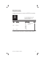
Appendix 1
PAGE/MENU Tables
Setup Page
PAGE Name
PAGE Contents
DISP
Display
Process Variable
Limit Setpoint
Limit Output
Time Over Setpoint
Peak Temperature
Alarm Output Status
PAGE#/MENU#*
P0/M1
P0/M2
P0/M3
P0/M4
P0/M5
P0/M6
SET
Set
Security Lock
Limit Setpoint
Limit Deadband
Event Input Function
Analog Output Enable
Controller Type
User Security Code
Ambient Temperature Low
Ambient Temperature High
Lower Display Disable
P1/M1
P1/M2
P1/M3
P1/M4
P1/M5
P1/M6
P1/M7
P1/M8
P1/M9
P1/M10
INPT
Input
Sensor Type
Display Units
Calibration Offset
Setpoint Low Limit
Setpoint Upper Limit
Sensor Calibration
Analog Output Zero Calibration
Analog Output Span Calibration
Factory Calibration Recovery
P2/M1
P2/M2
P2/M3
P2/M4
P2/M5
P2/M6
P2/M7
P2/M8
P2/M9
SCAL
Scaling
Analog Input Decimal Points
Analog Input Low
Analog Input High
Analog Process Output Low
Analog Process Output High
P3/M1
P3/M2
P3/M3
P3/M4
P3/M5
AL 1
Alarm #1
Alarm #1 Enable
Alarm #1 Type
Alarm #1 Relay
Alarm #1 Low Setpoint
Alarm #1 High Setpoint
Output #1 Deadband (Alarm Hysteresis)
Alarm #1 Inhibit
P4/M1
P4/M2
P4/M3
P4/M4
P4/M5
P4/M6
P4/M7
ALR2
Alarm #2
Alarm #2 Enable
Alarm #2 Type
Alarm #2 Relay
Alarm #2 Low Setpoint
Alarm #2 High Setpoint
Output #2 Deadband (Alarm Hysteresis)
Alarm #2 Inhibit
P5/M1
P5/M2
P5/M3
P5/M4
P5/M5
P5/M6
P5/M7
DIG
Digital Comm. Mode Selection
Baud Rate
Address
P6/M1
P6/M2
P6/M3
* For digital communications using the Ascii Line Mode, you will use PAGE#/MENU#
instead of the alphanumeric cues. For example, Alarm 1 Low Setpoint would be P4/M4.
Chromalox 3101 Operator's Manual
65
Security Levels
See pages 20-21 for details.
Security Levels and PAGE/MENU Contents
Level
Code
Description
A
---
Display Page and Security Lock
B
123
Display Page and Security Lock
C
458
Settings for:
Limit Control
Alarms
Input
Digital Communications
D
736
Calibration
Digital Input
Analog Process Output
Security Codes
Security Codes
66
Security
Level
A
B
C
D
Security
Code
--123
458
736
Adjust
Level
A
A, B
A, B, C
A, B, C, D
Chromalox 3101 Operator's Manual
Display Page
See page 24 for details.
Display Page
MENU
Description
Displays
PROC
Process Variable
Sensor Span
L SP
Limit Setpoint
Sensor Span
LOUT
Limit Output
0.0 TO 100.0%
TOSP
Time Over Setpoint
0 TO 999.9 MIN
PEAH
Peak Temperature
Instrument Sensor Span
ALR
Alarm Output Status
NONE
AL 1
AL 2
AL12
=
=
=
=
Security
A
No alarms
Alarm #1
Alarm #2
Alarm #1 and #2
Setup Page
See page 24 for details.
SET Page
MENU
Description
Displays
LOCH
Security Lock
0 to 9999
Factory Setting Security
L SP
Limit Setpoint
Instrument Sensor Span
DB
Limit Dead Band
0 to 100
ENTI
Event Input Function
NONE =
ARST =
AOUT
Analog Output Enable NONE =
PROC =
CONT
Controller Type
HI
LO
CODE
User Security Code
0 to 999
0-122
123-457
458-735
736-999
458
A
Span High
C
1°F
Disabled
Alarm Reset
ARST
Disabled
Process Variable
NONE
HI
0
=
=
=
=
Security level A
Security level B
Security level C
Security level D
ALO
Ambient Temp Low
-3 to 153
AHI
Ambient Temp High
-3 to 153
85
LDSP
Lower Display
Enable
ON = Enabled
OFF = Disabled
ON
Chromalox 3101 Operator's Manual
D
65
67
Input Page
See page 25 for details.
Input Page
MENU Description
SENS
Sensor Type
UNIT
Display Units
COFF
Calibration Offset
Available Settings
Factory Setting Security
Sensor Type selected here must
agree with dip switch settings.
J
= J Thermocouple
K
= K Thermocouple
T
= T Thermocouple
E
= E Thermocouple
R
= R Thermocouple
S
= S Thermocouple
B
= B Thermocouple
RTD
= 100 Pt RTD
(α = .00385)
4-20 = 4 to 20mA
0-5
= 0 to 5 Vdc
1-5
= 1 to 5 Vdc
NONE = none (analog inputs)
°F
= Degrees Fahrenheit
°C
= Degrees Celsius
J
°F
SPLL
SPUL
0 to ±100°F
0
(±6.25% of span for analog inputs)
Setpoint Low Limit Instrument Sensor Span
Span Low
Setpoint Upper Limit Instrument Sensor Span
Span High
CALS
Sensor Calibration
AO 0
Analog Output Zero 0 to 4095
Calibration
781
AO S
Analog Output Span 0 to 4095
3902
RECC
Factory Calibration RDY =
Recovery
---- =
DONE =
68
INLO =
INHI
=
DONE =
Input low
Input high
Calibration finished
Ready
Wait
Finished
C
INLO
D
RDY
Chromalox 3101 Operator's Manual
Custom Scaling
Page
See page 26 for details.
Custom Scaling Page
MENU
Description
Available Settings
DP
Analog Input Decimal Pts.
0
1
2
3
AINL
Analog Process Input Low
-500 to 5000
0.0
AINH
Analog Process Input High
-500 to 5000
100.0
AOTL
Analog Process Output Low Instrument Sensor Span Span Low
AOTH
Analog Process Output High Instrument Sensor Span Span High
=
=
=
=
Factory Setting Security
none
123.4
12.34
1.234
1
C
Alarm #1 Page
See page 26 for details.
Alarm #1 Page
MENU
Description
Available Settings
EN 1
Alarm 1 Enable
OFF
ON
=
=
Disabled
Enabled
Factory Setting Security
TYP1
Alarm 1 Type
NONE
HI
LO
HILO
PDE
-DE
DE
=
=
=
=
=
=
=
Disabled (off)
High Alarm
Low Alarm
High-Low Alarm
Plus Deviation Alarm
Minus Deviation Alm
Plus/Minus Dev Alm
NONE
RLY1
Alarm 1 Relay
NDE
=
NDE
NE
=
NDEL
=
NEL
=
normally de-energized
non-latching
normally energized
non-latching
normally de-energized
latching
normally energized
latching
OFF
ALO1
Alarm 1 Low Setpoint Instrument Sensor Span
Span Low
AHI1
Alarm 1 High Setpoint Instrument Sensor Span
Span High
DB1
Output 1 Dead Band 0 to 100°F
(Alarm Hysteresis)
(.00 to 6.25% of span for
analog inputs)
1°F
INH1
Alarm 1 Inhibit
OFF
OFF
ON
Chromalox 3101 Operator's Manual
C
69
Alarm #2 Page
See page 27 for details.
Alarm #2 Page
MENU
Description
Available Settings
EN 2
Alarm 2 Enable
OFF
ON
= Disabled
= Enabled
TYP2
Alarm 2 Type
NONE
HI
LO
HILO
PDE
-DE
DE
=
=
=
=
=
=
=
RLY2
Alarm 2 Relay
NDE
ALO2
Alarm 2 Low Setpoint Instrument Sensor Span
Span Low
AHI2
2 High Setpoint
Instrument Sensor Span
Span High
DB2
Output 2 Dead Band
(Alarm Hysteresis)
0 to 100°F
(.00 to 6.25% of span for
analog inputs)
1°F
INH2
Alarm 2 Inhibit
OFF
ON
OFF
70
Factory Settings Security
OFF
Disabled (off)
High Alm
Low Alm
High-Low Alm
Plus Deviation Alm
Minus Deviation Alm
Plus/Minus Dev Alm
= normally de-energized
non-latching
NE
= normally energized
non-latching
NDEL = normally de-energized
latching
NEL = normally energized
latching
C
NONE
NDE
Chromalox 3101 Operator's Manual
Digital
Communications
Page
See page 49 for details.
Digital Communications Page: DIG PAGE
MENU
Description
Available Settings
Factory Settings
Security
DIGT
Mode
Selection
OFF = Disabled
CPIF = Computer Interface
LINE = ASCII Line
CPIF
C
BAUD
Baud Rate
1200
2400
4800
9600
19.2K
19.2K
ADDR
Address
1 to 255
Chromalox 3101 Operator's Manual
1
71
72
Chromalox 3101 Operator's Manual
Index
Accuracy .............................................................................. 7, 8, 55, 57
Alarms
#1 Page ......................................................................................... 38
#2 Page ......................................................................................... 39
Latching/Non-Latching ......................................................37-39, 57
Reset ............................................................................................. 16
Wiring .........................................................................................7-13
Alarm Deadband ................................................................................ 57
Alarm Inhibit ................................................................................. 36, 57
Alarm Operation ................................................................................. 37
Alarm Outputs .................................................................................... 57
#1 Output ...................................................................................... 12
#2 Output ...................................................................................... 13
Alarm Relay Action ....................................................................... 37, 57
Alarm Types .................................................................................. 35, 57
Calibration .....................................................................................51-56
Analog Output Option ................................................................... 54
Display Calibration Offset.............................................................. 56
Factory Calibration Recovery ........................................................ 55
Sensor Input Calibration ............................................................... 52
ChromaSoft ........................................................................................ 45
Communications
RS232............................................................................................ 46
RS422A ......................................................................................... 47
RS485............................................................................................ 48
Control Parameters ...................................................................... 17, 20
Control Programming ......................................................................... 15
Digital Communications ......................................................7, 23, 45-49
ChromaSoft ................................................................................... 45
Hardware Setup ............................................................................ 45
Programming and Setup ............................................................... 49
Digital Input .............................................................................. 7, 37, 41
Dimensions ..................................................................................... 5, 58
Dip Switches ........................................................................................ 3
Analog Output Signal .................................................................... 43
RS422/RS485 Communications Switches .................................... 46
Sensor Input Switches .................................................................... 4
Displays ...................................................................................15-19, 24
Display Mode, Normal .................................................................. 15, 16
Error Messages .................................................................................. 61
Chromalox 3101 Operator's Manual
73
Indications .......................................................................................... 15
Input Type ....................................................................................... 4, 24
Inputs, Sensor .................................................................................8-10
Installation ............................................................................................ 3
Menu Selection .................................................................................. 18
Model Identification .............................................................................. 2
Mounting .............................................................................................. 5
Operation ......................................................................................15-22
Display Page ................................................................................. 22
MENU Selection ............................................................................ 18
MENU Value .................................................................................. 19
Operating Mode ............................................................................ 19
Page Selection .............................................................................. 18
Security Codes .............................................................................. 21
Setup Mode................................................................................... 18
Output
Alarm #1 .........................................................................7, 10-12, 35
Alarm #2 .........................................................................7, 10-12, 35
Analog Option ..........................................................................43-44
Wiring .................................................................................. 6, 11, 44
PAGE
Alarm #1 .................................................................................. 26, 38
Alarm #2 ................................................................................. 27, 39
Custom Scaling ....................................................................... 26, 44
Digital Communications ................................................................ 49
Display........................................................................................... 24
Input .............................................................................................. 25
Setup ................................................................................. 20, 24, 41
Peak Ambient Temperature Display ................................................... 33
Peak Temperature Display.................................................................. 33
Pushbuttons ..................................................................................15-19
Repair ................................................................................................. 63
Reset Pushbutton ......................................................................... 16, 18
RTD Inputs.......................................................................................... 52
Calibration ..................................................................................... 52
Wiring .............................................................................................. 9
74
Chromalox 3101 Operator's Manual
Security Codes ....................................................................... 20, 21, 24
Security Levels ............................................................................. 20, 21
Self-Tuning ................................................................................... 29, 88
Sensor
Setup, Menu .................................................................................. 25
Wiring .........................................................................................7-10
Setpoint .................................................... 16, 31, 35, 38, 39, 41, 57, 65
Setup Mode .................................................................................. 16, 18
Specifications ..................................................................................... 57
Thermocouple Inputs ........................................................................... 8
Timer
Time Over Setpoint ........................................................... 22, 24, 32
Troubleshooting .................................................................................. 61
Warranty ............................................................................................. 63
Wiring
Alarm #1 Output ............................................................................ 12
Alarm #2 Output ............................................................................ 12
Current Input Wiring (Loop Powered by controller)....................... 10
Current Input Wiring (Self-powered)................................................ 9
Digital Communications ................................................................ 46
Digital Input ................................................................................... 10
Good Wiring Practices .................................................................... 6
Instrument Power .......................................................................... 13
Limit Control Output...................................................................... 11
Output ........................................................................................... 11
Process Output Wiring .................................................................. 44
RS232 Wiring Connections ........................................................... 46
RS232 Connector Pin Designations .............................................. 47
RS422A Wiring Connections (4-wire) ............................................ 47
RS422A Connector Pin Designations ........................................... 48
RS485 Wiring Connections (2-wire) .............................................. 48
RS485 Connector Pin Designations .............................................. 48
Terminal Identification ..................................................................... 7
Voltage Input Wiring (Self-powered).............................................. 10
Chromalox 3101 Operator's Manual
75
76
Chromalox 3101 Operator's Manual
1382 HEIL QUAKER BLVD., LAVERGNE, TN 37086
Phone: (615) 793-3900
www.chromalox.com
1382 HEIL QUAKER BLVD., LAVERGNE, TN 37086
Phone: (615) 793-3900
www.chromalox.com