1
7521/7522/7522A/7523/7524/7527
Software User’s Manual
Warranty
All products manufactured by ICP DAS are warranted against
defective materials for a period of one year from the date of delivery
to the original purchaser.
Warning
ICP DAS assume no liability for damages resulting from the use
of this product. ICP DAS reserves the right to change this manual at
any time without notice. The information furnished by ICP DAS is
believed to be accurate and reliable. However, no responsibility is
assumed by ICP DAS for its use, nor for any infringements of patents
or other rights of third parties resulting from its use.
Copyright
Copyright 2000 by ICP DAS. All rights are reserved.
Trademark
The names used for identification only may be registered
trademarks of their respective companies.
7521/7522/7522A/7523/7524/7527 Software User’s Manual (Rev. 2.1, Jul/2005, 7PS-000-21) ----- 1
Tables of Contents
1.
INTRODUCTION
3
1.1 SOFTWARE INSTALLATION & DEMO PROGRAMS.......................................................................................7
1.2 QUICK START1:CONNECTING TO THE 7521..............................................................................................9
1.3 QUICK START2: CONNECTING TO SINGLE, REMOTE-RS232-DEVICE.....................................................15
1.4 QUICK START3: CONNECTING TO MULTI-REMOTE-RS232-DEVICES ....................................................20
1.5 DOWNLOADING NEW FIRMWARE TO 7521.............................................................................................23
1.6 TYPICAL APPLICATIONS .........................................................................................................................26
2.
CONNECTING TO THE HP34401A
34
2.1 THE 7521 & THE HP34401A .................................................................................................................34
2.2 THE PC & THE HP34401A ....................................................................................................................35
2.3 A SINGLE-7522 & SINGLE-HP34401A..................................................................................................37
2.4 MULTI-7522 & MULTI-HP34401A .......................................................................................................44
2.5 A SINGLE-7523 & TWO-HP34401A......................................................................................................46
2.6 MULTI-7523S & MULTI-HP34401AS ....................................................................................................48
3.
COMMAND SETS
50
3.1 $AAA[ADDR] ........................................................................................................................................52
3.2 $AABN[BAUD RATE].............................................................................................................................53
3.3 $AADN[DATA-BIT] ...............................................................................................................................54
3.4 $AAPN[DATA-BIT]................................................................................................................................55
3.5 $AAON[STOP-BIT] ................................................................................................................................56
3.6 $AA6(ID) ..............................................................................................................................................57
3.7 $AA7 ………………………………………………………………………………………………….58
3.8 $AAC[DELIMITER] ................................................................................................................................59
3.9 $AAD ………………………………………………………………………………………………….60
3.10 (DELIMITER)AA(BYPASS) ......................................................................................................................61
3.11 $AAK[CHECKSUM] ...........................................................................................................................62
3.12 $AATN[CRLFMODE]............................................................................................................................63
3.13 $AAW ...................................................................................................................................................64
3.14 $AAXV .................................................................................................................................................65
3.15 $AAYN .................................................................................................................................................66
3.16 $AAZNV...............................................................................................................................................67
3.17 #** ………………………………………………………………………………………………….68
3.18 $AA4 ………………………………………………………………………………………………….69
3.19 $AA5 ………………………………………………………………………………………………….70
3.20 $AAF ………………………………………………………………………………………………….71
3.21 $AAM………………………………………………………………………………………………….71
3.22 $AA2 ………………………………………………………………………………………………….72
3.23 ~** ………………………………………………………………………………………………….73
3.24 ~AA0 ………………………………………………………………………………………………….73
3.25 ~AA1 ………………………………………………………………………………………………….74
3.26 ~AA2 ………………………………………………………………………………………………….75
3.27 ~AA3ETT .............................................................................................................................................76
3.28 ~AA4P & ~AA4S .................................................................................................................................77
3.29 ~AA5P & ~AA5S .................................................................................................................................78
3.30 $AAU ………………………………………………………………………………………………….79
3.31 $AAL(DATA)..........................................................................................................................................80
3.32 $AAR ………………………………………………………………………………………………….81
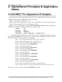
4.
OPERATIONAL PRINCIPLES & APPLICATION NOTES
82
4.1 DI1/INIT* PIN OPERATION PRINCIPLES ................................................................................................82
4.2 D/O OPERATING PRINCIPLES .................................................................................................................83
4.3 D/I OPERATING PRINCIPLES ...................................................................................................................83
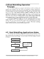
4.4 DUAL WATCHDOG OPERATION PRINCIPLE ............................................................................................84
4.5 HOST WATCHDOG APPLICATIONS NOTES .............................................................................................84
4.6 MODULE WATCHDOG APPLICATIONS NOTES ........................................................................................85
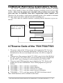
4.7 SOURCE CODE OF THE 7521/7522/7523 .................................................................................................85
7521/7522/7522A/7523/7524/7527 Software User’s Manual (Rev. 2.1, Jul/2005, 7PS-000-21) ----- 2
1.
Introduction
Introduction
There are many RS-232 devices used in industry applications.
Nowadays, linking all these RS-232 devices together for both
automation & information important. Usually, these devices are far
away from the host-PC. In modern situation, multi-serial card linking
is inefficient. Our 752x series products can link multiple RS-232
devices via a single RS-485 network. This network protocol offers
stability, reliability and simple cabling while delivering a low –cost,
easy-to-maintain product..
Addressable RS-232 Converter
Most RS-232 devices don’t support device addresses. Our I-752X
series can assign a unique address to any RS-232 device installed in a
RS-485 network. Once the host-PC sends a command with a device
address to the RS-485 network, the destination-752x will remove the
address field & pass the other commands to its local RS-232 device.
The response of this local RS-232 device will be returned to the hostPC via the I-752x.
Master-type Addressable RS-232 Converter
ICPDAS’ 752x products are unique. Our 752X products are Mastertype converters, while other converters are Slave-type. Slave-type
converters are helpless without a host-PC. In real industrial
applications, customers are not satisfied with Slave-type converters
because they can not adapt to individual demands. The powerful 752x
series analyzes local RS-232 devices, D/I or D/O without a host-PC.
Refer to Application 5~9 for more information.
Onboard 1K byte Queue-buffer
The I-752X equips a 1K byte queue-buffer for its local RS-232
device. All input data can be stored in the queue-buffer until the hostPC has time to read it. These features allow the host-PC to link
thousands of RS-232 devices without losing any data.
7521/7522/7522A/7523/7524/7527 Software User’s Manual (Rev. 2.1, Jul/2005, 7PS-000-21) ----- 3
Onboard D/I signal trigger
The I-752X is equipped with 3-channels of digital input for sensor
interfacing. These D/I are linked to a photo sensor/switch to act as a
signal. They also can be used as general purpose D/I. The 752X can
read & analyze these D/I without the help of host-PC.
Onboard D/O for emergency control
The I-752X equips 3-channels of digital output for emergency
control. The D/O can directly drive relay or led. They can be used to
control the local devices for emergency event. The 752x can control
these D/O without the help of host-PC.
3000V isolation on RS-485 site
The COM2 of the I-752x is an isolated RS-485 port with 3000V
isolation. This isolation will protect the local RS-232 devices from
transient noises coming from RS-485 network.
Self-Tuner ASIC inside
The I-752X Self-Tuner ASIC for RS-485 port. This chip can auto
detect and control the send/receive direction of the RS-485 network.
Therefore the application programs don’t have to take care of the
direction control of the RS-485 network.
Embedded control capabilities
Besides Intelligent Communication Controller, the I-752X series
products can be used as an embedded controller. Every I-752X
controller has a, MiniOS7, embedded O.S.. The MiniOS7 provides
equivalent functions of ROM DOS and has more features. The user can
use well-developed libraries and demo programs to implement his
controller.
Wide range selection
The I-752X series products have I-7521, I-7521D, I-7522, I-7522D,
I-7522A, I-7522A, I-7523, I-7523D, I-7524, I-7524D, I-7527 and I7527D. The I-7521 provides one RS-232 port, one RS-485 port, 3
digital input channels and 3 digital output channels. The I-7522
provides two RS-232 ports, one RS-485 port, two digital input channels
and one digital output channel. The I-7522A provides one RS-232/RS-
7521/7522/7522A/7523/7524/7527 Software User’s Manual (Rev. 2.1, Jul/2005, 7PS-000-21) ----- 4
485 port, one RS-485 port, one RS-422/RS-485 port, 5 digital input
channels and 5 digital output channels. The I-7523 provides three RS232 ports, one RS-485 port. The I-7524 provides 4 RS-232 ports, two
RS-485 ports, 1 digital input channels and 1 digital output channels.
The I-7527 provides seven RS-232 ports, two RS-485 ports, 1 digital
input channels and 1 digital output channels. The COM 1 of the I-7521,
I-7522, I-7522A, I-7523, I-7524 and I-7527 can be used as RS-232 port
or RS-485 port.
The 7188XC/XB & 752X series
The 7521/22/22A/23/24/27 is really an embedded controller before
any firmware is downloaded. After downloading the firmware, the
7521/22/22A/23/24/27 acts as an “Intelligent Communication
Controller”. The only difference between the 7521/22/23 & the
7188XC is the 3000V isolation on the RS-485 port. In general, the
7521/22/23 is equivalent to 7188XC+7510. Therefore the
7521/7522/7523 can be used as an embedded controller with an
isolated RS-485 port. The only difference between the 7522A/24/27 &
the 7188XB is the 3000V isolation on the RS-485 port. In general, the
7522A/24/27 is equivalent to 7188XB+7510. Therefore the
7522A/7524/7527 can be used as an embedded controller with an
isolated RS-485 port.
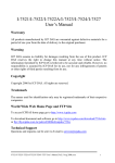
Cost Effective Solution
The 7188/7188XA/7188XB/7188XC is designed as an embedded
controller. Therefore, an any software can be downloaded to them. If
the firmware for “Intelligent Communication Controller” is
downloaded to the into 7188/7188XA/7188XB/7188XC, they will act
as an “Intelligent Communication Controller”.
7188XC
A cost-effective “embedded controller”.
+
Intelligent
Communication
Controller
Firmware
A cost-effective “Intelligent Communication
Controller” (without isolation on RS-485 port)
7521/7522/7522A/7523/7524/7527 Software User’s Manual (Rev. 2.1, Jul/2005, 7PS-000-21) ----- 5
Features
Built-in “Addressable RS-232 Converter” firmware
Supports about 30 well-defined commands
Supports Dual-Watchdog commands
Supports Power-up value & safe value for D/O
The source code of firmware is open & well-documented
User can modify the source code according to their specific
requirements.
The firmware can monitor the onboard D/I and control the
onboard D/O in real-time according to user’s requirements
The firmware can monitor the RS-232 device and control the
onboard D/O in real-time according to user’s requirements
The 7521 supports one RS-232 device
The 7522 supports two RS-232 devices
The 7522A supports one RS-232 device
The 7523 supports three RS-232 devices
The 7524 supports four RS-232 devices
The 7527 supports seven RS-232 devices
Watchdog timer provides fault tolerance and recovery
Low power consumption
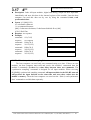
Ordering Information
7521 : Single-channel “Intelligent Communication Controller”
7521D : 7521 with 5-digit 7-seg LED.
7522 : Dual-channel “Intelligent Communication Controller”
7522D : 7522 with 5-digit 7-seg LED.
7522A : Single-channel “Intelligent Communication Controller”
7522AD : 7522A with 5-digit 7-seg LED.
7523 : Three-channel “Intelligent Communication Controller”
7523D : 7523 with 5-digit 7-seg LED.
7524 : Four-channel “Intelligent Communication Controller”
7524D : 7522 with 5-digit 7-seg LED.
7527 : Seven-channel “Intelligent Communication Controller”
7527D : 7522 with 5-digit 7-seg LED.
7521/7522/7522A/7523/7524/7527 Software User’s Manual (Rev. 2.1, Jul/2005, 7PS-000-21) ----- 6
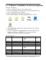
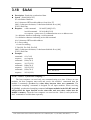
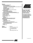
1.1 Software installation & demo programs
Software Installation:
• make a working directory in your computer, then
• insert the installation CD and wait for autorun(or Run auto32.exe)
• click “Toolkits(Softwares)/ Manuals”
• click “718XA/B/C & 7521/2/2A/3/4/7 Series”
• click “Demo Program”, the following like window is shown:
Select all the files and directories and copy them to the working
location/directory
• Copy the 7188X.EXE/7188XW.EXE to the PATH directory, for
example, C:\DOS or C:\WINDOWS, then you can execute
7188X.EXE/7188XW.EXE from any location.
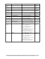
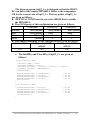
Files description:
File name
Xbyymmdd.img
Location
7188XB\DEMO\
7522A.C
7522A.EXE
7524.C
7524.EXE
7527.C
7527.EXE
Xcyymmdd.img
7188XB\DEMO\TC30\7522A
7188XB\DEMO\TC30\7522A
7188XB\DEMO\TC30\7524
7188XB\DEMO\TC30\7524
7188XB\DEMO\TC30\7527
7188XB\DEMO\TC30\7527
7188XC\DEMO\
7521.C
7521.EXE
7522.C
7522.EXE
7523.C
7523.EXE
7188XC\DEMO\BC\7521
7188XC\DEMO\BC\7521
7188XC\DEMO\BC\7522
7188XC\DEMO\BC\7522
7188XC\DEMO\BC\7523
7188XC\DEMO\BC\7523
Description
The image file for MiniOS7
yy:00 2000
mm: month
dd: day
The source code of 7522A
The firmware of 7522A
The source code of 7524
The firmware of 7524
The source code of 7527
The firmware of 7527
The image file for MiniOS7
yy:00 2000
mm: month
dd: day
The source code of 7521
The firmware of 7521
The source code of 7522
The firmware of 7522
The source code of 7523
The firmware of 7523
Hardware
7522A/7524/
7527
7522A
7522A
7524
7524
7527
7527
7521/7522/
7523
7521
7521
7522
7522
7523
7523
7521/7522/7522A/7523/7524/7527 Software User’s Manual (Rev. 2.1, Jul/2005, 7PS-000-21) ----- 7
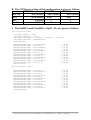
7188XC\
Containing source code for Quick Start.
com.h
7188XC\start
Header file for all quick start program
hp34401a.c
7188XC\start
PC link to HP34401A
hp22_1.c
7188XC\start
7522 link to HP 34401A
hp22_m.c
7188XC\start
Multi-7522 link to HP 34401A
hp23_1.c
7188XC\start
7523 link to HP 34401A
hp23_m.c
7188XC\start
Multi-7523 link to HP 34401A
7521ODM1
7521ODM2
7188XC\DEMO\BC\
7188XC\DEMO\BC\
7521ODM3
7188XC\DEMO\BC\
7521ODM4
7188XC\DEMO\BC\
7521ODM5
7188XC\DEMO\BC\
lib
7188XB\DEMO\
7521+ real time control D/IO
7521+
real time control AD&DA
7521+
real time control Event counter
7521+
real time control Sensor & Multiplex
7521+
real time monitor HP34401A & alarm
control
7188xbs.lib for SMALL program.
(TC/BC++/MSC/MSVC++)
start
7521/7522
/7523
7521/7522
/7523
7521/7522
/7523
7521/7522
/7523
7521/7522
/7523
7521/7522
/7523
7521/7522
/7523
7521
7521
7521
7521
7521
7522A/7524/
7527
7188xbl.lib for LARGE program.
(TC/BC++/MSC/MSVC++)
7188xb.h All the functions declared
are in the 7188xb.h, please use
#include”7188xb.h”. 7188xb.h is put on
the same directory as 7188xbs.lib
lib
7188XC\
7188xs.lib for SMALL program.
(TC/BC++/MSC/MSVC++)
7521/7522/
7523
7188xl.lib for LARGE program.
(TC/BC++/MSC/MSVC++)
7188x.h All the functions declared are
in the 7188x.h, please use
#include”7188x.h”. 7188x.h is put on
the same directory as 7188xs.lib
7521/7522/7522A/7523/7524/7527 Software User’s Manual (Rev. 2.1, Jul/2005, 7PS-000-21) ----- 8
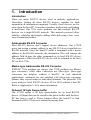
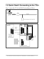
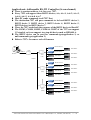
1.2 Quick Start1:Connecting to the 7521
Step 1: connect the 7521 to the RS-485 networking as follows:
7520
RS-232
RS-485
Host PC
7521/7522/22A/7523/7524/7527
7520
7520R
Host-PC
6
7
8
9
1
10
+VS
9
8
RS-232
Signal
1
2
2
3
3
4
4
5
5
4
3
2
1
6
7
5
8
4
9
Female 9-pin D-sub
7521/7521D
7522/7522D
7522A/7522AD
7523/7523D
7524/7524D
7527/7527D
7
6
5
Male 9-pin D-sub
Com 1/2/3/4 or
UART port
GND
3
Date-
2
Date+
1
GND
13
Ext. GND
+VS
12
Ext. 24V
D2-
11
D2+
10
9
RS-485
Signal
8
7
6
Male 9-pin D-sub
7521/7522/7522A/7523/7524/7527 Software User’s Manual (Rev. 2.1, Jul/2005, 7PS-000-21) ----- 9
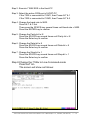
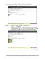
Step 2: Execute 7188X.EXE in the Host-PC
Step 3: Select the active COM port of HOST-PC
If the 7520 is connected to COM1, then Press ALT & 1
If the 7520 is connected to COM2, then Press ALT & 2
Step 4: Change the baud rate to 9600
Press ALT & C first
Then press the SPACE-key several times until baud rate = 9600
Press the ENTER-key to confirm
Step 5: Change the Parity-bit to N
Press the SPACE-key several times until Parity-bit = N
Press the Enter-key to confirm
Step 6: Change the Data-bit to 8
Press the SPACE-key several times until Data-bit = 8
Press the Enter-key to confirm
Step 7: Change the Stop-bit to 1
Press the SPACE-key several times until Stop-bit = 1
Press the Enter-key to confirm
Step 8:Change the 7188x to Line-Command-mode
Press ALT & L
The screen will show as follows:
7521/7522/7522A/7523/7524/7527 Software User’s Manual (Rev. 2.1, Jul/2005, 7PS-000-21) ----- 10
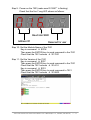
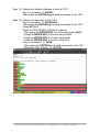
Step 9: Power-on the 7521(make sure DI1/INIT* is floating)
Check that the five 7-seg LED shows as follows:
Baud rate=9600
Address=01
Reserved for user
Step 10: Get the Module-Name of the 7521
Key-in command
$01M
Then press the ENTER-key to send command to the 7521
Check that the 7521 echoes
!017521
Step 11: Get the Version of the 7521
Key-in command
$01F
Then press the ENTER-key to send command to the 7521
Check that the 7521 echoes
!01A1.0
Key-in command
$012
Then press the ENTER-key to send command to 7521
Check that the 7521 echoes
!016800
7521/7522/7522A/7523/7524/7527 Software User’s Manual (Rev. 2.1, Jul/2005, 7PS-000-21) ----- 11
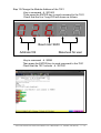
Step 12:Change the Module-Address of the 7521
Key-in command
$01A02
Then press the ENTER-key to send command to the 7521
Check that the five 7-seg LED will shows as follows:
Baud rate=9600
Address=02
Reserved for user
Key-in command
$02M
Then press the ENTER-key to send command to the 7521
Check that the 7521 echoes
!027521
7521/7522/7522A/7523/7524/7527 Software User’s Manual (Rev. 2.1, Jul/2005, 7PS-000-21) ----- 12
Step 13:Change the baud rate of the 7521
Key-in command
$02B0115200
Then press the ENTER-key to send command to the 7521
Check that the five 7-seg LED shows as follows:
Baud rate=115200
Address=02
Reserved for user
Press ALT & C
Press the SPACE-KEY until 115200 is shown
Then press the ENTER-KEY to confirm baud rate=115200
Press the ENTER-KEY to confirm parity-bit=N
Press the ENTER-KEY to confirm data-bit=8
Press the ENTER-KEY to confirm stop-bit=1
Key-in command
$02M
Then press the ENTER-key to send command to the 7521
Check that the 7521 echoes
!027521
Key-in command
$022
Then press the ENTER-key to send command to the 7521
Check that the 7521 echoes
!02A800
7521/7522/7522A/7523/7524/7527 Software User’s Manual (Rev. 2.1, Jul/2005, 7PS-000-21) ----- 13
Step 14: Change the Module-Address of the the 7521
Key-in command
$02A01
Then press the ENTER-key to send command to the 7521
Step 15: Change the baud rate of the 7521
Key-in command
$01B09600
Then press the ENTER-key to send command to the 7521
Press ALT & C
Press the SPACE-KEY until 9600 is shown
Then press the ENTER-KEY to confirm baud rate=9600
Press the ENTER-KEY to confirm parity-bit=N
Press the ENTER-KEY to confirm data-bit=8
Press the ENTER-KEY to confirm stop-bit=1
Key-in command
$01M
Then press the ENTER-key to send command to the 7521
Check the 7521 echoes
!017521
7521/7522/7522A/7523/7524/7527 Software User’s Manual (Rev. 2.1, Jul/2005, 7PS-000-21) ----- 14
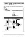
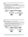
1.3 Quick Start2: Connecting to Single,
Remote-RS232-Device
Step 1: connect the 7521 to the RS-485 networking & remote-PC as
follows:
7520
R S -2 3 2
R S -4 8 5
H o st P C
7 5 2 1 /7 5 2 2 /7 5 2 2 A /7 5 2 3 /7 5 2 4 /7 5 2 7
R e m o te P C
7520
7520R
H o s t-P C
7
8
9
1
1
S ig n a l
2
2
3
3
4
4
5
7
8
9
1
2
3
4
4
S ig n a l
3
2
1
5
4
9
R e m o te -P C
R S -2 3 2
6
8
7 5 2 1 /7 5 2 1 D
7 5 2 2 /7 5 2 2 D
7 5 2 3 /7 5 2 3 D
5
7
7
F e m a le 9 -p in D - s u b
C o m 1 /2 /3 /4 o r
U A R T p o rt
6
9
6
5
M a le 9 -p in D -s u b
10
+VS
8
R S -2 3 2
6
GND
3
D a te -
2
D a te +
1
GND
13
E x t. G N D
+VS
12
E x t. 2 4 V
D2-
11
D2+
10
9
R S -4 8 5
S ig n a l
8
7
6
M a le 9 -p in D - s u b
5
M a le 9 -p in D -s u b
C o m 1 /2 /3 /4 o r
U A R T p o rt
7521/7522/7522A/7523/7524/7527 Software User’s Manual (Rev. 2.1, Jul/2005, 7PS-000-21) ----- 15
7520
7520R
H o s t-P C
6
7
8
9
1
1
2
3
3
4
4
5
9
6
5
8
4
9
3
D a te -
2
D a te +
1
7 5 2 2 A /7 5 2 2 A D
7 5 2 4 /7 5 2 4 D
7 5 2 7 /7 5 2 7 D
R e m o te -P C
8
7
7
F e m a le 9 - p in D - s u b
U A R T p o rt
7
9
6
5
6
10
+VS
8
R S -2 3 2
S ig n a l
2
M a le 9 -p in D - s u b
C o m 1 /2 /3 /4 o r
GND
1
2
R S -2 3 2
S ig n a l
GND
14
E x t. G N D
+VS
13
E x t. 2 4 V
D2-
12
D2+
11
IN IT *
10
RXD1
9
TXD1
8
GND
7
R S -4 8 5
S ig n a l
3
4
5
M a le 9 -p in D - s u b
C o m 1 /2 /3 /4 o r
U A R T p o rt
Step 2:
Execute 7188X.EXE in the Host-PC
Refer to Step3 through o Step 8 of Quick Start 1 to change
COM port & status to 9600, N, 8, 1
Step 3:
Execute 7188X.EXE in the Remote-PC
Refer to Step3 through Step 8 of Quick Start 1 to change
COM port & status to 9600, N, 8, 1
Step 4:
Host-PC Sends abcde to Remote-PC
Keyin
:01abcde
Press the Enter-key to send command string to the 7521
Check that the response-string from Remote-PC is abcde
The screen should be shown on Host-PC as follows:
7521/7522/7522A/7523/7524/7527 Software User’s Manual (Rev. 2.1, Jul/2005, 7PS-000-21) ----- 16
7521/7522/7522A/7523/7524/7527 Software User’s Manual (Rev. 2.1, Jul/2005, 7PS-000-21) ----- 17
The screen on the Remote-PC should show as follows:
Step 5:
Host-PC Sends 12345 to Remote-PC
Keyin
:0112345
Press the Enter-key to send command string to the 7521
Check that the response-string from Remote-PC is 12345
The screen should be shown on Host-PC as follows:
7521/7522/7522A/7523/7524/7527 Software User’s Manual (Rev. 2.1, Jul/2005, 7PS-000-21) ----- 18
The screen on the Remote-PC should show as follows:
Note: If no Remote-PC is available. One can connect TxD and Rxd to
the same COM port to test:
7521/7522/7522A/7523/7524/7527 Software User’s Manual (Rev. 2.1, Jul/2005, 7PS-000-21) ----- 19
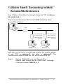
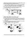
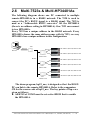
1.4 Quick Start3: Connecting to MultiRemote-RS232-Devices
Step 1: Refer to Quick Start1 for wiring & change the 7521 to Address02, & 9600, N, 8, 1
Step 2: connect the second 7521 to the RS-485 networking & two
remote-PCs as follows:
7520
RS-485
RS-232
Host PC
7521/7522/7522 A
7523/7524/7527
address 01/01/01
01/01/01
Remote PC #1
7521/7522/7522A
7523/7524/7527
address 02/03/02
04/05/08
Remote PC #2
Now there are two 7521s in the RS-485 network. The module address
of one 7521 is address-01, the other is address-02. The
communication status of these two 7521 will be same as N, 8, 1
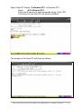
Step 3:
Execute 7188X.EXE in the two, Remote-PCs
Refer to Step3 through Step 8 of Quick Start 1 to change
COM port & status to 9600, N, 8, 1
7521/7522/7522A/7523/7524/7527 Software User’s Manual (Rev. 2.1, Jul/2005, 7PS-000-21) ----- 20
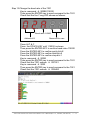
Step 4:Host-PC Sends To-Remote-PC1 to Remote-PC1
Keyin
:01To-Remote-PC1
Press the Enter-key to send command string to the 7521
The screen on the Host-PC will show as follows:
The screen on the Host-PC will show as follows:
7521/7522/7522A/7523/7524/7527 Software User’s Manual (Rev. 2.1, Jul/2005, 7PS-000-21) ----- 21
Step 5:Host-PC Sends To-Remote-PC2 to Remote-PC2
Keyin
:02To-Remote-PC2
Press the Enter-key to send command string to the 7521
Keyin
:02To-Remote-PC2
Press the Enter-key to send command string to the 7521
The screen on the Host-PC will show as follows:
The screen on Remote-PC-2 will show as follows:
7521/7522/7522A/7523/7524/7527 Software User’s Manual (Rev. 2.1, Jul/2005, 7PS-000-21) ----- 22
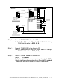
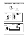
1.5 Downloading New Firmware to 7521
Step 1: connect the 7521 to the RS-485 networking as follows:
RS-232
Host PC
7521/7522/7522A
7523/7524/7527
7521/7521D
GND
7522/7522D
+VS
7523/7523D
Host-PC
6
7
8
9
1
RS-232
Signal
5
4
2
3
3
2
4
1
10
Ext. GND
9
Ext. 24V
9
8
7
6
5
Male 9-pin D-sub
Male 9-pin D-sub
Com 1/2/3/4 or
UART port
7 5 2 2 A /7 5 2 2 A D
7 5 2 4 /7 5 2 4 D
7 5 2 7 /7 5 2 7 D
R e m o te -P C
6
7
8
9
1
2
R S -2 3 2
S ig n a l
GND
14
E x t. G N D
+VS
13
E x t. 2 4 V
D2-
12
D2+
11
IN IT *
10
RXD1
9
TXD1
8
GND
7
3
4
5
M a le 9 -p in D - s u b
C o m 1 /2 /3 /4 o r
U A R T p o rt
7521/7522/7522A/7523/7524/7527 Software User’s Manual (Rev. 2.1, Jul/2005, 7PS-000-21) ----- 23
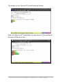
Step 2: Connect DI1/INIT* to GND
Step 3: Go to the directory of 7521/7522/7523 driver in the host
computer &execute 7188x.exe
Step 4: refer to Step 3~Step7 of Quick Star1 to change the
configuration to 115200,N,8,1
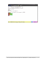
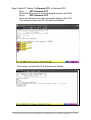
Key in:dir&Enter-Key and the screen will show as follows:
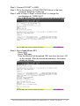
Step 5: Key-in load &Enter-KEY
Press Alt-E
Key-in 7521.exe
Then the MiniOs7 will download 7521.exe from the host –PC
to the module. After the download operation, the screen
shows as follows:
7521/7522/7522A/7523/7524/7527 Software User’s Manual (Rev. 2.1, Jul/2005, 7PS-000-21) ----- 24
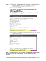
Step 6 : If Step 5 fails, please use the del command to delete all files in
7521/7522/7523. Then download autoexec.bat &
7521.exe(7522.exe, 7523.exe) to the module.
Key-in del & Enter-KEY
The MiniOS7 will prompt you to confirm deletion of files.
Key-in Y & Enter-KEY
Key-in dir & Enter-KEY
The MiniOS7 will show you there are no files in the controller
( total file number is 0 ).
refer to Step 5, download autoexec.bat & 7521.exe, the screen
will show as follows:
Step 7: disconnect the DI1/INIT* pin from GND & power-off then poweron the 7521/7522/7523.The MiniOS7 will auto execute the new
firmware.
7521/7522/7522A/7523/7524/7527 Software User’s Manual (Rev. 2.1, Jul/2005, 7PS-000-21) ----- 25
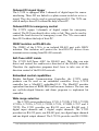
1.6 Typical Applications
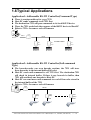
Application1: Addressable RS-232 Controller(Command Type)
There is a unique address for every 7521.
Host-PC sends commands to all 7521 first
The destination-7521 will pass commands to its local RS232 device
Then, the 7521 sends back the response of the RS232 device to Host-PC
Refer to 7521.c for source code of firmware
7520
RS232
RS485
Host PC
7521
(#02)
7521
(#01)
HP 34401A
HP 34401A
7521
(#AA)
HP 34401A
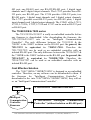
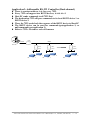
Application2: Addressable RS-232 Controller(Null-command
Type)
The barcode-reader can scan barcode anytime, the 7521 will store
these barcodes in the internal buffer(1K bytes)
Host-PC sends null-command to all 7521 first. The destination-7521
will check its internal buffer. If there is any barcode in buffer, then
7521 will send back one barcode to Host-PC.
Host-PC can send more null-commands to read all barcodes stored in
the internal buffer of the 7521
Refer to 7521.c for source code of firmware
7520
RS485
7521
(#01)
RS232
7521
(#02)
RS232
7521
(#AA)
RS232
7521/7522/7522A/7523/7524/7527 Software User’s Manual (Rev. 2.1, Jul/2005, 7PS-000-21) ----- 26
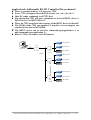
Application3: Addressable RS-232 Controller (Dual-channel)
There is a unique address, AA, for every 7522.
Every 7522 can support two RS232 devices, AA & AA+1
Host-PC sends commands to all 7522 first
The destination-7522 will pass commands to its local RS232 device 1 or
RS232 device 2.
Then, the 7522 sends back the response of the RS232 device to Host-PC
The RS232 device can be used for command-type(application 1) or
null-command type(application 2)
Refer to 7522.c for source code of firmware
RS232
7520
RS485
Host PC
7522
(#01)
7522
(#03)
RS-232 Device
RS-232 Device
RS-232 Device
RS-232 Device
7522
(#AA)
RS-232 Device
RS-232 Device
7521/7522/7522A/7523/7524/7527 Software User’s Manual (Rev. 2.1, Jul/2005, 7PS-000-21) ----- 27
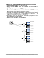
Application4: Addressable RS-232 Controller(Three-channel)
There is a unique address, AA, for every 7523.
Every 7523 can support three RS232 devices, AA, AA+1 & AA+2
Host-PC sends commands to all 7523 first
The destination-7523 will pass commands to its local RS232 device 1,
RS232 device 2 or RS232 device 3.
Then, the 7523 sends back the response of the RS232 device to Host-PC
The COM4 of the 7523 can support 1/2 stop-bit, so it can support two
stop-bit device such as HP34401A.
The RS232 device can be used for command-type(application 1) or
null-command type(application 2)
Refer to 7523.c for source code of firmware
RS-232 Device
7520
RS-232 Device
RS232
Host PC
7523
(#01)
RS485
HP 34401A
RS-232 Device
RS-232 Device
7523
(#04)
HP 34401A
RS-232 Device
RS-232 Device
7523
(#XX)
HP 34401A
7521/7522/7522A/7523/7524/7527 Software User’s Manual (Rev. 2.1, Jul/2005, 7PS-000-21) ----- 28
Application5: Addressable RS-232 Controller(Four-channel)
There is a unique address, AA, for every 7524.
Every 7524 can support three RS232 devices, AA, AA+1, AA+2 &
AA+3
Host-PC sends commands to all 7524 first
The destination-7524 will pass commands to its local RS232 device 1,
RS232 device 2, RS232 device 3 or RS232 device 4.
Then, the 7524 sends back the response of the RS232 device to Host-PC
The COM3 & COM4 of the 7524 can support 1/2 stop-bit, so it can
support two stop-bit device such as HP34401A.
The RS232 device can be used for command-type(application 1) or
null-command type(application 2)
Refer to 7524.c for source code of firmware
RS-232 Device
7520
RS-232 Device
RS232
Host PC
7524
(#01)
HP 34401A
HP 34401A
RS485
HP 34401A
HP 34401A
7524
(#05)
HP 34401A
HP 34401A
HP 34401A
HP 34401A
7523
(#XX)
HP 34401A
HP 34401A
7521/7522/7522A/7523/7524/7527 Software User’s Manual (Rev. 2.1, Jul/2005, 7PS-000-21) ----- 29
Application6: Addressable RS-232 Controller (Seven-channel)
There is a unique address, AA, for every 7527.
Every 7523 can support three RS232 devices, AA, AA+1, AA+2, AA+3,
AA+4, AA+5, AA+6 & AA+7
Host-PC sends commands to all 7527 first
The destination-7527 will pass commands to its local RS232 device 1,
RS232 device 2, RS232 device 3, RS232 device 4, RS232 device 5,
RS232 device 6 or RS232 device 7.
Then, the 7527 sends back the response of the RS232 device to Host-PC
The COM3, COM4, COM5, COM6 & COM7 of the 7527 can support
1/2 stop-bit, so it can support two stop-bit device such as HP34401A.
The RS232 device can be used for command-type(application 1) or
null-command type(application 2)
Refer to 7527.c for source code of firmware
RS-232 Device
HP 34401A
7520
RS-232 Device
RS232
Host PC
HP 34401A
7527
(#01)
RS485
HP 34401A
HP 34401A
HP 34401A
RS-232 Device
HP 34401A
RS-232 Device
7527
(#08)
HP 34401A
HP 34401A
HP 34401A
HP 34401A
RS-232 Device
HP 34401A
RS-232 Device
HP 34401A
7527
(#XX)
HP 34401A
HP 34401A
HP 34401A
7521/7522/7522A/7523/7524/7527 Software User’s Manual (Rev. 2.1, Jul/2005, 7PS-000-21) ----- 30
Application7: Real time D/I Monitoring & D/O Alarm (Master
type)
Refer to applications 1 & 2 for more information.
The 7521 will scan & analyze the onboard D/I, if the D/I states a match
with the alarm states, the onboard D/O will drive the alarm device for
alarm or safety control.
All control operations of D/I & D/O are done by the 7521. The host-PC
only reads the values of D/I & D/O for system monitoring.
Refer to 7521ODM1.c for the source code of firmware
7520
RS485
7521
(#01)
D/I
7521
(#AA)
D/I
D/O
RS232 Device
D/O
RS232 Device
Application8: Real time A/D Monitoring & D/A Control(Master
type)
Refer to applications 1 & 2 for more information.
The X301 supports one A/D & one D/A & it can be installed into the
7521. The 7521+X301 can read & analyze the A/D in real time. The
output of D/A is controlled based on the value of A/D.
All control operations of A/D & D/A are done by the 7521. The hostPC only reads the values of A/D & D/A for system monitoring.
Refer to 7521ODM2.c for source code of firmware
7520
RS485
7521
(#01)
7521
(#AA)
D/A
A/D
RS232 Device
A/D
D/A
RS232 Device
7521/7522/7522A/7523/7524/7527 Software User’s Manual (Rev. 2.1, Jul/2005, 7PS-000-21) ----- 31
Application9: 8-channels of long time Event-counters(Master type)
Refer to applications 1 & 2 for more information.
The X100 supports 8-channel of D/I. The 7521+X100 can read &
analyze these 8 event-counters in real time. The timing diagram of the
event-counter will be latched until host-PC’s clear command.
All analysis operations are done by the 7521. The host-PC only read
the timing values of the event-counter for system monitoring.
Refer to 7521ODM3.c for source code of firmware
7520
RS485
7521
(#01)
7521
(#AA)
X8
X8
Event Counter
Event Counter
RS232 Device
RS232 Device
Application10: Multiplex Control(Master type)
Refer to applications 1 & 2 for more information.
The onboard D/O of the 7521 can drive relay directly. The onboard D/I
can link to photo-sensors for event triggering. The 7521+DN-PR4 can
trigger by photo-sensor & control the multiplex to select the expected
analog signal.
All control operations are done by the 7521. The host-PC can read the
3-channel A/D signals without the multiplex control.
Refer to 7521ODM4.c for source code of firmware
7520
RS485
photo sensor
7521
(#01)
photo sensor
7521
(#AA)
D/I
D/I
RS232
device
RS232
device
D/O
D/O
DN-PR4
DN-PR4
A/I
A/I
7521/7522/7522A/7523/7524/7527 Software User’s Manual (Rev. 2.1, Jul/2005, 7PS-000-21) ----- 32
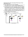
Application11: Real time Analog Signal Monitoring & Alarm
Control(Master type)
Refer to applications 1 & 2 for more information.
The COM1 of host-PC is used as a host-485 network. Host-PC will
send commands & receive responses through this RS485 network.
The COM2 of host-PC is used as an emergency-485 network. All 7522s
will automatically monitor the analog signal connected to HP34401A.
If the emergency event occurs, the 7522 will send the emergency
command to this RS485 network. If multi-7522s send emergency
commands to host-PC at the same time, these 7522s will re-send
emergency commands to host-PC until confirmation from host-PC.
All analysis operations are done by the 7522. The host-PC only reads
the analog values for system monitoring.
Refer to 7522ODM5.c for source code of firmware
7520
Host-485 Network
COM1
COM2
COM2
7520
COM1
COM3
COM2
COM1
7522
(#01)
HP 34401A
COM3
7522
(#AA)
HP 34401A
Emergency-485 Network
7521/7522/7522A/7523/7524/7527 Software User’s Manual (Rev. 2.1, Jul/2005, 7PS-000-21) ----- 33
2.
Connecting to the HP34401A
2.1 The 7521 & the HP34401A
The stop-bit of the HP34401A must be two stop-bit. The
COM1 of the7521, 7522 & 7523 can support 1 stop-bit only. So
COM1 cannot link to the HP34401A. That is to say, the 7521 can not
link to the HP34401A.
The COM3 of the 7522 & COM3/COM4 of the 7523 can
support 2 stop-bit, so they can link to the HP34401A. The 7522 can
link to one HP34401A. The 7523 can link to two HP34401As. Refer
to Sec. 2.2 ~ Sec. 2.6 for more information.
7521/7522/7522A/7523/7524/7527 Software User’s Manual (Rev. 2.1, Jul/2005, 7PS-000-21) ----- 34
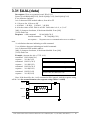
2.2
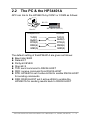
The PC & the HP34401A
APC can link to the HP34401A by COM1 or COM2 as follows:
RS-232
Host PC
COM port of PC
TxD(3)
RxD(2)
DTR(4)
DSR(6)
GND(5)
HP 34401A (RS-232)
multimeter
TxD(3)
RxD(2)
DTR(4)
DSR(6)
GND(5)
The default setting of theHP34401A are given as follows:
Baud rate=9600
Data-bit=7
Parity-bit=EVEN
Stop-bit=2
TXD: send command to RS232-HOST
RXD: receive command from RS232-HOST
DTR: HP34401A set it active-HIGH to enable RS232-HOST
for sending commands
DSR: RS232-HOST set it active-HIGH to enable the
HP34401A for sending results back to RS232-HOST
7521/7522/7522A/7523/7524/7527 Software User’s Manual (Rev. 2.1, Jul/2005, 7PS-000-21) ----- 35
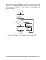
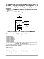
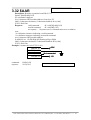
The demo program, hp34401a.c, is designed so that a PC cab
connect to a HP34401A. Refer to the companion CD for the
source code of hp34401a.c. The flow chart of hp34401a.c is
given as follows:
start
Set multimeter
into remotecontrol mode
Anykey
pressed?
Y
Set multimeter
back to local
mode
N
Ask for
measuring
Acquire
reading
end
Note: the COM port of PC should be 16550 compatible.
7521/7522/7522A/7523/7524/7527 Software User’s Manual (Rev. 2.1, Jul/2005, 7PS-000-21) ----- 36
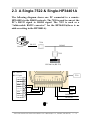
2.3 A Single-7522 & Single-HP34401A
The following diagram shows one PC connected to a remoteHP34401A in the RS485 network. The 7520 is used to convert the
PC’s RS232 signal to RS485 signal. The 7522 is used as a
“Addressable RS232 converter” for the HP34401A(there is no
address setting in the HP34401A).
7520
RS-232
RS-485
Host PC
7522
HP 34401A (RS-232)
HP 34401A
RS-232 port
DSR
GND
Txd
RxD
7522
9
8
7
6
5
4
3
2
1
GND
24V
RS-485D+
RS-485D-
圖5
7521/7522/7522A/7523/7524/7527 Software User’s Manual (Rev. 2.1, Jul/2005, 7PS-000-21) ----- 37
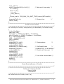
The demo program, hp22_1.c, is designed so that the HOST-PC
can link to a remote-HP34401A. Refer to the companion CD for
the source code of hp22_1.c. The key points of hp22_1.c are given
as follows:
RTS3 of COM3 must be set active-HIGH first to enable the
HP34401A.
The flow chart of hp22_1.c is given as follows:
start
Set multimeter to
remote-control
mode
Anykey
pressed?
Y
Set multimeter
back to local
mode
N
Ask for
measuring
end
Acquire
reading
Note: the COM port of PC should be 16550 compatible.
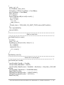
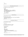
The source code of hp22_1.c is given as follows:
#include "com.h"
#include <conio.h>
#include <stdio.h>
#include <string.h>
#include <dos.h>
#include <time.h>
/*===========================================
Transmit one char to ComNo
========================================== */
int TxCharCOM(int ComNo, char ch)
{
clock_t c1, c2;
int time_wait;
int ComBase;
if(ComNo == COM1) ComBase = Com1Base;/* Set base address */
else if(ComNo == COM2) ComBase = Com2Base;
c1 = clock();
7521/7522/7522A/7523/7524/7527 Software User’s Manual (Rev. 2.1, Jul/2005, 7PS-000-21) ----- 38
time_wait=0;
while(!(inportb(LSR) & 0x20)) {
/* Wait until line ready */
c2 = clock();
if(c1 != c2) {
c1 = c2;
time_wait++;
}
if(time_wait > COM_MAX_RX_WAIT_TIME) return(RxTimeOut);
}
outportb(TxD, ch);
/* Output char
*/
return(TxOK);
}
/*===========================================
Initial Port of ComNo
========================================== */
int InitCOM(int ComNo, unsigned long int BaudRate, int DataFormat)
{
int br, ComBase;
char MSB, LSB;
if(ComNo == COM1) ComBase = Com1Base;
else if(ComNo == COM2) ComBase = Com2Base;
br = 115200L/BaudRate;
MSB = (br&0xff00)>>8;
LSB = br&0xff;
disable();
outportb(LCR, 0x80);
/* Set baudrate
*/
outportb(DLL, LSB);
outportb(DLH, MSB);
outportb(LCR, DataFormat);
/* Set DataFormat
*/
outportb(FCR,0xc1);
/*enable FIFO, 14 bit buffer*/
outportb(IER, 0);
/* Disable all Interrupt */
inportb(LSR);
inportb(RxD);
outportb(MCR, 0x09);
outportb(IER, 0x01);
/* Int. while receive data */
outportb(TxD, 0x0d);
enable();
return(0);
}
/*===========================================
Reset ReceiveQueue of ComNo
========================================== */
/*=======================================
Polling a char from ComNo
Return RxOK
RxTimeOut
========================================== */
int PollRxChar(int ComNo, char* ch)
7521/7522/7522A/7523/7524/7527 Software User’s Manual (Rev. 2.1, Jul/2005, 7PS-000-21) ----- 39
{
clock_t c1, c2;
int ComBase, wait_time;
if(ComNo==COM1) ComBase = Com1Base;
else ComBase = Com2Base;
wait_time=0;
c1 = clock();
while((inportb(LSR) & 0x0f)!=0x01) {
c2 = clock();
if(c1 != c2) {
c1 = c2;
wait_time++;
}
if(wait_time > COM_MAX_RX_WAIT_TIME) return(RxTimeOut);
};
*ch=inportb(RxD);
return(RxOK);
}
/*===========================================
Wait a clock tick
========================================== */
void WaitClock(int count)
{
int temp;
clock_t c1, c2;
for(temp=0; temp<count; temp++) {
c1 = clock();
c2 = clock();
while(c2==c1) {
c2 = clock();
}
}
}
ComSetting com[2];
/*===========================================
Initial HP in serial port
========================================== */
void InitHP(int ComNo)
{
com[ComNo].ComNo = ComNo;
com[ComNo].BaudRate = 9600L;
com[ComNo].DataFormat = Data8bit + NonParity + Stop1bit; //RS-485
setting
com[ComNo].CheckSum = CHKSUMdisable;
OpenCOM(ComNo);
HPSendCommand(ComNo, ":02SYST:REM");
HPSendCommand(ComNo, ":02*CLS");
WaitClock(18);
7521/7522/7522A/7523/7524/7527 Software User’s Manual (Rev. 2.1, Jul/2005, 7PS-000-21) ----- 40
}
/*===========================================
Close HP in serial port
========================================== */
void CloseHP(int ComNo)
{
HPSendCommand(ComNo, ":02*CLS");
HPSendCommand(ComNo, ":02SYST:LOC");
CloseCOM(ComNo);
}
/*==========================================
Send Command to HP in serial port
========================================= */
int HPSendCommand(int ComNo, char *str)
{
int i;
unsigned char chk=0;
for(i=0; str[i]!=0; i++)
{
if(TxCharCOM(com[ComNo].ComNo, str[i]) == TxTimeOut)
return(TxTimeOut);
chk += str[i];
}
if(TxCharCOM(com[ComNo].ComNo, 0x0d)==TxTimeOut)
return(TxTimeOut);
//RS-485 setting
return(TxOK);
}
/*===========================================
Receive Command to HP in serial port
========================================== */
int HPReceiveCommand(int ComNo, char *str)
{
int end_of_rx=0, i=0;
for(i=0; !end_of_rx; i++) {
str[i] = 0;
switch(PollRxChar(com[ComNo].ComNo, str+i)) {
case RxOK :
if( str[i] == 0x0d) //RS-485 setting
{
str[i] = 0;
end_of_rx = 1;
}
break;
case RxTimeOut :
return(RxTimeOut);
case RxOverFlow :
return(RxOverFlow);
}
7521/7522/7522A/7523/7524/7527 Software User’s Manual (Rev. 2.1, Jul/2005, 7PS-000-21) ----- 41
}
i--;
return(i);
}
/*===========================================
Read analog value from HP
========================================== */
int ReadHP(int ComNo, double *AI)
{
int ret;
float A;
char str1[80] ;
HPSendCommand(ComNo, ":02READ?");
ret = HPReceiveCommand(ComNo, str1);
if(ret < 0) return(ret);
*AI = atof(str1);
return(HP_OK);
}
/*===========================================
Initial COM port
===========================================*/
int OpenCOM(int ComNo)
{
InitCOM(com[ComNo].ComNo, com[ComNo].BaudRate,
com[ComNo].DataFormat);
return(0);
}
/*===========================================
Close/Restore COM port
===========================================*/
int CloseCOM(int ComNo)
{
return(0);
}
int ShowErrorCode(int error_code);
int main(char argc, char* argv[])
{
int ret, ComNo;
double AI;
int Bye=0;
int i;
char str[80];
if(argc!=2) {
printf("No COM port assigned\n");
printf(" Use HP 1 for COM1, HP2 for COM2");
exit(0);
}
if(argv[1][0] == '1') {
7521/7522/7522A/7523/7524/7527 Software User’s Manual (Rev. 2.1, Jul/2005, 7PS-000-21) ----- 42
printf("Connect HP in COM1\n");
ComNo = COM1;
}
else if(argv[1][0] == '2') {
printf("Connect HP in COM2\n");
ComNo = COM2;
}
else {
printf(" Use HP 1 for COM1, HP2 for COM2");
exit(0);
}
InitHP(ComNo);
while(!Bye)
{
if(kbhit())
{
Bye=1;
}
if(HPSendCommand(ComNo, ":02READ?")<0)
ShowErrorCode(ret);
if((ret=HPReceiveCommand(ComNo, str))>0)
printf("\nreading=%sV",str);
else ShowErrorCode(ret);
WaitClock(12);
}
CloseHP(ComNo);
return(0);
}
int ShowErrorCode(int error_code)
{
printf("\n");
switch(error_code) {
case RxOK : printf("RxOK
");
break;
case TxOK :
printf("TxOK
");
break;
case HP_OK : printf("HP OK
");
break;
case TxTimeOut :printf("TxTimeOut ");
break;
case RxTimeOut :printf("RxTimeOut ");
break;
case RxOverFlow :printf("RxOverFlow ");
break;
defualt :
printf("error=%d ", error_code);break;
}
return(0);
}
/* 1 */
/* 2 */
/* 3 */
/* -10 */
/* -11 */
/* -12 */
7521/7522/7522A/7523/7524/7527 Software User’s Manual (Rev. 2.1, Jul/2005, 7PS-000-21) ----- 43
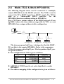
2.4
Multi-7522 & Multi-HP34401A
The following diagram shows one PC connected to a multiple,
remote-HP34401As in the RS485 network. The 7520 is used to
convert the PC’s RS232 signal to a RS485 signal. The 7522 is
used as a “Addressable RS232 converter” for the
HP34401A(there is no address setting in HP34401A).
Every 7522 has a unique address in the RS485 network. Every
hp34401A shares the same address-range with its 7522, so every
HP34401A has a unique address in this configuration.
7520
RS-232
RS-485
Host PC
7522 #1
HP 34401A (RS-232)
#2
7522 #3
HP 34401A (RS-232)
#4
7522 #5
HP 34401A (RS-232)
#6
The demo program, hp22_m.c, is designed so that the HOSTPC can link to the remote-HP34401A. Refer to the companion
CD for the source code of hp22_m.c. The key points of hp22_m.c
are given as follows:
The configuration of 7522 is given as follows:
COM2(485)
COM3(232)
baud rate
9600(default)
9600(default)
Parity
None(default)
Even
data
8(default)
7
stop bit
1(default)
2
All RTS3 of COM3 must be set active-high first to enable
HP34401A.
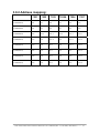
The address mapping of this configuration is given as follows:
7521/7522/7522A/7523/7524/7527 Software User’s Manual (Rev. 2.1, Jul/2005, 7PS-000-21) ----- 44
No.of 7522
#1
#3
#5
Address of 7522
01h
03h
05h
No.of HP
Address of
HP34401A
02h
04h
06h
#2
#4
#6
The flow chart of hp22_m.c is given as follows:
start
Set
multimeters
to remotecontrol mode
Anykey
pressed?
N
Y
key ’q’or ’Q’
pressed?
Y
Set multimeter
back to local
mode
end
N
Ask for key-in
multimeter
command
Send
command to
multimeter
Receiving the
multimeter
response
Execution examples:
7521/7522/7522A/7523/7524/7527 Software User’s Manual (Rev. 2.1, Jul/2005, 7PS-000-21) ----- 45
2.5 A Single-7523 & Two-HP34401A
The following diagram shows one PC connected to two remoteHP34401As in a RS485 network. The 7520 is used to convert the
PC’s RS232 signal to a RS485 signal. The 7523 is used as a
“Addressable RS232 converter” for the HP34401A(there is no
address setting in HP34401A). One 7523 can connect two
HP34401As.
RS-232
7520
RS-485
Host PC
7523
HP 34401A #1 (RS-232) HP 34401A #2 (RS-232)
7523
GND
24V
HP 34401A #1
RS-232 port
9
8
7
DSR
6
GND
5
4
Txd
3
RxD
2
1
HP 34401A #2
RS-232 port
DSR
GND
Txd
RxD
9
8
7
6
5
4
3
2
1
7521/7522/7522A/7523/7524/7527 Software User’s Manual (Rev. 2.1, Jul/2005, 7PS-000-21) ----- 46
The demo program, hp23_1.c, is designed so that the HOSTPC can link to the remote-HP34401A. Refer to the companion
CD for the source code of hp23_1.c. The key points of hp23_1.c
are given as follows:
All RTS3 of COM3 must be set active-HIGH first to enable
the HP34401A.
The COM-ports of this configuration are given as follows:
COM2(485)
COM3(232)
COM4(232)
Baud rate
9600 (default)
9600 (default)
9600 (default)
Parity
None (default)
Even
Even
data
8 (default)
7
7
stop bit
1 (default)
2
2
The address mapping of this configuration is given as follows:
address of 7523
Corresponding COM3
Corresponding COM4
address
address
01h
02h
03h
The InitHP() and CloseHP() of hp23_1.c are given as
follows:
void InitHP(int ComNo)
{
com[ComNo].ComNo = ComNo;
com[ComNo].BaudRate = 9600L;
com[ComNo].DataFormat = Data8bit + NonParity + Stop1bit;
com[ComNo].CheckSum = CHKSUMdisable;
OpenCOM(ComNo);
HPSendCommand(ComNo,
HPSendCommand(ComNo,
HPSendCommand(ComNo,
HPSendCommand(ComNo,
WaitClock(18);
":02SYST:REM");
":02*CLS");
":03SYST:REM");
":03*CLS");
//
//
//
//
#1
#1
#2
#2
HP
HP
HP
HP
void CloseHP(int ComNo)
{
HPSendCommand(ComNo, ":02*CLS");
HPSendCommand(ComNo, ":02SYST:LOC");
HPSendCommand(ComNo, ":03*CLS");
HPSendCommand(ComNo, ":03SYST:LOC");
CloseCOM(ComNo);
}
//
//
//
//
#1
#1
#2
#2
HP
HP
HP
HP
}
7521/7522/7522A/7523/7524/7527 Software User’s Manual (Rev. 2.1, Jul/2005, 7PS-000-21) ----- 47
2.6
Multi-7523s & Multi-HP34401As
The following diagram shows one PC connected to multiple
remote-HP34401As in a RS485 network. The 7520 is used to
convert the PC’s RS232 signal to a RS485 signal. The 7523 is
used as a “Addressable RS232 converter” for the HP34401A
(there is no address setting in HP34401A). One 7523 can connect
to two HP34401A.
Every 7523 has a unique address in the RS485 network. Every
HP34401A shares the same address-range with its 7523, so every
HP34401A has a unique address in this configuration.
7520
RS-232
RS-232
Host PC
7523
HP 34401A (RS-232) address=02h
HP 34401A (RS-232) address=03h
address=01h
RS-485
HP 34401A (RS-232) address=05h
7523
HP 34401A (RS-232) address=06h
address=04h
HP 34401A (RS-232) address=08h
7523
HP 34401A (RS-232) address=09h
address=07h
The demo program, hp23_m.c, is designed so that the HOSTPC can link to the remote-HP34401A. Refer to the companion
CD for the source code of hp23_m.c. The key points of 1hp.c are
given as follows:
All RTS3 of COM3 must be set active-HIGH first to enable
the HP34401A.
7521/7522/7522A/7523/7524/7527 Software User’s Manual (Rev. 2.1, Jul/2005, 7PS-000-21) ----- 48
The COM-port setting of this configuration is given as follows:
COM2(485)
COM3(232)
COM4(232)
baud rate
9600 (default)
9600 (default)
9600 (default)
parity
None (default) Even
Even
data
8 (default)
7
7
stop bit
1 (default)
2
2
The InitHP() and CloseHP() of hp23_M.c are given as follows:
void InitHP(int ComNo)
{
com[ComNo].ComNo = ComNo;
com[ComNo].BaudRate = 9600L;
com[ComNo].DataFormat = Data8bit + NonParity + Stop1bit;
com[ComNo].CheckSum = CHKSUMdisable;
OpenCOM(ComNo);
HPSendCommand(ComNo,
HPSendCommand(ComNo,
HPSendCommand(ComNo,
HPSendCommand(ComNo,
HPSendCommand(ComNo,
HPSendCommand(ComNo,
HPSendCommand(ComNo,
HPSendCommand(ComNo,
HPSendCommand(ComNo,
HPSendCommand(ComNo,
HPSendCommand(ComNo,
HPSendCommand(ComNo,
WaitClock(18);
":02SYST:REM");
":02*CLS");
":03SYST:REM");
":03*CLS ");
":05SYST:REM");
":05*CLS ");
":06SYST:REM");
":06*CLS ");
":08SYST:REM");
":08*CLS ");
":09SYST:REM");
":09*CLS ");
}
void CloseHP(int ComNo)
{
HPSendCommand(ComNo, ":02*CLS");
HPSendCommand(ComNo, ":02SYST:LOC");
HPSendCommand(ComNo, ":03*CLS");
HPSendCommand(ComNo, ":03SYST:LOC");
HPSendCommand(ComNo, ":05*CLS");
HPSendCommand(ComNo, ":05SYST:LOC");
HPSendCommand(ComNo, ":06*CLS");
HPSendCommand(ComNo, ":06SYST:LOC");
HPSendCommand(ComNo, ":08*CLS");
HPSendCommand(ComNo, ":08SYST:LOC");
HPSendCommand(ComNo, ":09*CLS");
HPSendCommand(ComNo, ":09SYST:LOC");
CloseCOM(ComNo);
}
//
//
//
//
//
//
//
//
//
//
//
//
#1
#1
#2
#2
#3
#3
#4
#4
#5
#5
#6
#6
HP
HP
HP
HP
HP
HP
HP
HP
HP
HP
HP
HP
//
//
//
//
//
//
//
//
//
//
//
//
#1
#1
#2
#2
#3
#3
#4
#4
#5
#5
#6
#6
HP
HP
HP
HP
HP
HP
HP
HP
HP
HP
HP
HP
7521/7522/7522A/7523/7524/7527 Software User’s Manual (Rev. 2.1, Jul/2005, 7PS-000-21) ----- 49
3.
Command Sets
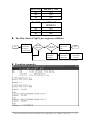
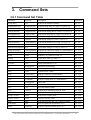
3.0.1 Command Set Table
Command
Response
Description
Reference
$AAA[addr]
!AA
Read/Set the Module Address
Sec. 3.1
$AABN[baud rate]
!AA[baud rate] Read/Set Baud Rate of COM-1/2/3/4/5/6/7/8
Sec. 3.2
$AADN[data-bit]
!AA[data-bit]
Sec. 3.3
$AAPN[data-bit]
!AA[parity-bit] Read/Set the Parity-Bit of COM-1/2/3/4/5/6/7/8
Sec. 3.4
$AAON[data-bit]
!AA[stop-bit]
Read/Set the Stop-Bit of COM-1/2/3/4/5/6/7/8
Sec. 3.5
$AA6(ID)
!AA
Set the ID-string of COM-1/3/4/5/6/7/8
Sec. 3.6
$AA7
!AA(ID)
Read the ID-string of COM-1/3/4/5/6/7/8
Sec. 3.7
$AAC[delimiter]
!AA[delimiter]
Read/Set the delimiter of COM-1/3/4/5/6/7/8
Sec. 3.8
$AAD
!AA(delimiter)
Read the delimiter of COM-1/3/4/5/6/7/8
Sec. 3.9
Bypass data-string to COM-1/3/4/5/6/7/8
Sec. 3.10
(delimiter)AA(bypass) !AA
Read/Set the Data-Bit of COM-1/2/3/4/5/6/7/8
$AAK[checksum]
!AA(checksum) Read/Set the checksum-status of COM2(RS485) Sec. 3.11
$AATN[CrLfMode]
!AA(CrLfMode) Read/Set the end-char of COM-1/2/3/4
Sec. 3.12
$AAW
!AAS
Read the CTS_status of COM-1/3
Sec. 3.13
$AAXV
!AA
Set the RTS_state of COM-1/3
Sec. 3.14
$AAYN
!AA
Read the onboard DI-1/2/3
Sec. 3.15
$AAZNV
!AA
Set the onboard D/O-1/2/3
Sec. 3.16
#**
No Response
Synchronized Sampling
Sec. 3.17
$AA4
!AASV
Read the synchronized data
Sec. 3.18
$AA5
!AAS
Read the Reset- status
Sec. 3.19
$AAF
!AA(number)
Read the firmware version number
Sec. 3.20
$AAM
!AA(name)
Read the module name
Sec. 3.21
$AA2
!AABDPK
Read the confguraton of COM2(RS485)
Sec. 3.22
~**
No Response
Host is OK
Sec. 3.23
~AA0
!AASS
Read the module status
Sec. 3.24
~AA1
!AA
Reset the module status
Sec. 3.25
~AA2
!AASTT
Read the host watchdog status & value
Sec. 3.26
~AA3ETT
!AA
Enable the host watchdog timer
Sec. 3.27
~AA4P/~AA4S
!AAV
Read power-on/safe value
Sec. 3.28
~AA5P/~AA5S
!AAV
Set power-on/safe value
Sec. 3.29
$AAU
(data)
Read data from the RS-232 COM port buffer.
Sec. 3.30
$AAL(data)
!AA
Write to expansion board DO 0/1/2/3
Sec. 3.31
$AAR
!AA(data)
Read the expansion board DI-0/1/2/3
Sec. 3.32
7521/7522/7522A/7523/7524/7527 Software User’s Manual (Rev. 2.1, Jul/2005, 7PS-000-21) ----- 50
3.0.2 Address mapping:
7521
7522
7523
7522A
7524
7527
COM1(RS232)
AA
AA
AA
AA
AA
AA
COM2(RS485)
AA
AA
AA
AA
AA
AA
COM3(RS232)
N/A
AA+1
AA+1
AA+1
AA+1
AA+1
COM4(RS232)
N/A
N/A
AA+2
N/A
AA+2
AA+2
COM5(RS232)
N/A
N/A
N/A
N/A
AA+3
AA+3
COM6(RS232)
N/A
N/A
N/A
N/A
N/A
AA+4
COM7(RS232)
N/A
N/A
N/A
N/A
N/A
AA+5
COM8(RS232)
N/A
N/A
N/A
N/A
N/A
AA+6
7521/7522/7522A/7523/7524/7527 Software User’s Manual (Rev. 2.1, Jul/2005, 7PS-000-21) ----- 51
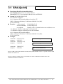
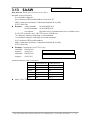
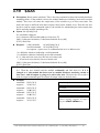
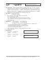
3.1 $AAA[addr]
7521/7522/7522A/7523/7524/7527
Description: Read/Set the module address
$AAA[addr][chk](CrLf) set module address
$AAA[chk](CrLf) read module address stored in EEPROM
Syntax: $AAA[addr][chk](CrLf)
$ is a delimiter character
AA=2-character HEX module address, from 00 to FF
[chk]=2-character checksum, if checksum disabled no [chk]
(CrLf)=End-Char
Response: valid command
!AA[chk](CrLf)
invalid command
?AA[chk](CrLf)
no response :
syntax error or communication error or address error
! is a delimiter character indicating a valid command
? is a delimiter character indicating an invalid command
AA=2-character HEX module address
[chk]=2-character checksum, if checksum disabled no [chk]
(CrLf)=End-Char
Example:
command: $01A02(CrLf)
address 01 is changed to 02
response : !02(CrLf)
command: $02AA0(CrLf)
address 02 is changed to 0xA0
response : !A0(CrLf)
command:
response :
$00A(CrLf)
!02(CrLf)
address stored in EEPROM=02
NOTE1: THE AA WILL BE SHOWN IN THE (LED1,LED2). REFER TO SEC. 1.2 QUICK START 1 FOR
MORE INFORMATION.
NOTE2: CONNECT THE DI1/INIT* TO GND & USE $00A COMMAND TO READ OUT THE
ADDRESS STORED IN EEPROM.
7521/7522/7522A/7523/7524/7527 Software User’s Manual (Rev. 2.1, Jul/2005, 7PS-000-21) ----- 52
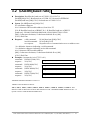
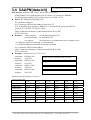
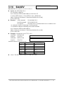
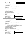
3.2 $AABN[baud rate]
7521/7522/7522A/7523/7524/7527
Description: Read/Set the baud rate of COM-1/2/3/4./5/6/7/8
$AABN[chk](CrLf): Read baud rate of COM-1/2/3/4 stored in EEPROM
$AABN(baud rate)[chk](CrLf): Set baud rate of COM-1/2/3/4
Syntax: $AABN[baud rate][chk](CrLf)
$ is a delimiter character
AA=2-character HEX module address, from 00 to FF
N=0 Read/Set baud rate of RS485, N=1 Read/Set baud rate of RS232
[baud rate]: 300/600/1200/2400/4800/9600/19200/38400/57600/115200
[chk]=2-character checksum, if checksum disabled no [chk]
(CrLf)=End-Char
Response: valid command
!AA[baud rate][chk](CrLf)
invalid command
?AA[chk](CrLf)
no response :
syntax error or communication error or address error
! is a delimiter character indicating a valid command
? is a delimiter character indicating an invalid command
AA=2-character HEX module address
[chk]=2-character checksum, if checksum disabled no [chk]
(CrLf)=End-Char
Example: (Assume the AA of 7523 is 01)
command: $01B0115200(CrLf) Changes RS485(COM2) to 15200 BPS
response : !01(CrLf)
command: $01B19600(CrLf)
Changes RS232(COM1) to 9600 BPS
response : !01(CrLf)
command: $02B138400(CrLf)
Changes RS232(COM3) to 38400 BPS
response : !02(CrLf)
command: $03B157600(CrLf)
Changes RS232(COM4) to 57600 BPS
response : !03(CrLf)
ADDRESS MAPPING:REFER TO PAGE 51
SHORT-CODE FOR BAUD RATE:
300=1, 600=2, 1200=3, 2400=4, 4800=5, 9600=6, 19200=7, 38400=8, 57600=9, 115200=A. THE
SHORT-CODE OF BAUD RATE WILL BE SHOWN IN THE 7-SEGMENT LED3. REFER TO SEC. 1.2
QUICK START 1 FOR MORE INFORMATION.
7521/7522/7522A/7523/7524/7527 Software User’s Manual (Rev. 2.1, Jul/2005, 7PS-000-21) ----- 53
7521/7522/7522A/7523/7524/7527
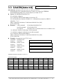
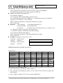
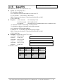
3.3 $AADN[data-bit]
DESCRIPTION: READ/SET THE DATA-BIT OF COM-1/2/3/4/5/6/7/8
$AADN[chk](CrLf): Read the data-bit of COM-1/2/3/4 stored in EEPROM
$AADN(data-bit)[chk](CrLf): Set the data-bit of COM-1/2/3/4
Syntax: $AADN[data-bit][chk](CrLf)
$ is a delimiter character
AA=2-character HEX module address, from 00 to FF
N=0 Read/Set the data-bit of RS485, N=1 Read/Set the data-bit of RS232
[data-bit]: 7 or 8
[chk]=2-character checksum, if checksum disabled no [chk]
(CrLf)=End-Char
Response: valid command
!AA[data-bit][chk](CrLf)
invalid command
?AA[chk](CrLf)
no response :
syntax error or communication error or address error
! is a delimiter character indicating a valid command
? is a delimiter character indicating an invalid command
AA=2-character HEX module address
[chk]=2-character checksum, if checksum disabled no [chk]
(CrLf)=End-Char
Example: (Assume the AA of 7523 is 01)
command: $01D08(CrLf)
Changes data-bit of RS485(COM2) to 8
response : !01(CrLf)
command: $01D17(CrLf)
Changes data-bit of RS232(COM1) to 7
response : !01(CrLf)
command: $02D17(CrLf)
Changes data-bit of RS232(COM3) to 7
response : !02(CrLf)
command: $03D17(CrLf)
Changes data-bit of RS232(COM4) to 7
response : !03(CrLf)
ADDRESS MAPPING:REFER TO PAGE 51
VALID DATA-BIT:
COM1
COM2
COM3
COM4
COM5
COM6
COM7
COM8
7521
7/8
7/8
N/A
N/A
N/A
N/A
N/A
N/A
7522
7/8
7/8
7/8
N/A
N/A
N/A
N/A
N/A
7522A
7/8
7/8
7/8
N/A
N/A
N/A
N/A
N/A
7523
7/8
7/8
7/8
7/8
N/A
N/A
N/A
N/A
7524
7/8
7/8
7/8
7/8
7/8
N/A
N/A
N/A
7527
7/8
7/8
7/8
7/8
7/8
7/8
7/8
7/8
7521/7522/7522A/7523/7524/7527 Software User’s Manual (Rev. 2.1, Jul/2005, 7PS-000-21) ----- 54
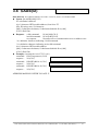
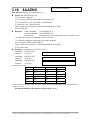
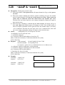
3.4 $AAPN[data-bit]
7521/7522/7522A/7523/7524/7527
DESCRIPTION: READ/SET THE PARITY-BIT OF COM-1/2/3/4/5/6/7/8
$AAPN[chk](CrLf): Read the parity-bit of COM-1/2/3/4 stored in EEPROM
$AAPN(parity-bit)[chk](CrLf): Set the parity-bit of COM-1/2/3/4
Syntax: $AAPN[parity-bit][chk](CrLf)
$ is a delimiter character
AA=2-character HEX module address, from 00 to FF
N=0 Read/Set the parity-bit of RS485, N=1 Read/Set the parity-bit of RS232
[parity-bit]: 0=NONE, 1=EVEN, 2=ODD
[chk]=2-character checksum, if checksum disabled no [chk]
(CrLf)=End-Char
Response: valid command
!AA[data-bit][chk](CrLf)
invalid command
?AA[chk](CrLf)
no response :
syntax error or communication error or address error
! is a delimiter character indicating a valid command
? is a delimiter character indicating an invalid command
AA=2-character HEX module address
[chk]=2-character checksum, if checksum disabled no [chk]
(CrLf)=End-Char
Example: (Assume the AA of 7523 is 01)
command: $01P00(CrLf)
Changes parity-bit of RS485(COM2) to NONE
response : !01(CrLf)
command: $01P10(CrLf)
Changes parity-bit of RS232(COM1) to NONE
response : !01(CrLf)
command: $02P11(CrLf)
Changes parity-bit of RS232(COM3) to EVEN
response : !02(CrLf)
command: $03P12(CrLf)
Changes parity-bit of RS232(COM4) to ODD
response : !03(CrLf)
ADDRESS MAPPING:REFER TO PAGE 51
VALID PARITY-BIT:
7521
7522
7522A
7523
7524
7527
COM1(RS232)
N/E/O
N/E/O
N/E/O
N/E/O
N/E/O
N/E/O
COM2(RS485)
N/E/O
N/E/O
N/E/O
N/E/O
N/E/O
N/E/O
COM3(RS232)*
N/A
N/E/O
N/E/O
N/E/O
N/E/O
N/E/O
COM4(RS232)
N/A
N/A
N/A
N/E/O
N/E/O
N/E/O
COM5(RS232)
N/A
N/A
N/A
N/A
N/E/O
N/E/O
COM6(RS232)
N/A
N/A
N/A
N/A
N/A
N/E/O
COM7(RS232)
N/A
N/A
N/A
N/A
N/A
N/E/O
COM8(RS232)
N/A
N/A
N/A
N/A
N/A
N/E/O
*The Com3 of 7522A is RS-422/485
7521/7522/7522A/7523/7524/7527 Software User’s Manual (Rev. 2.1, Jul/2005, 7PS-000-21) ----- 55
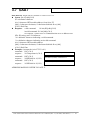
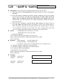
3.5 $AAON[stop-bit]
7522/7523/7524/7527
DESCRIPTION: READ/SET THE STOP-BIT OF COM-3/4/5/6/7/8
$AAON[chk](CrLf): Read the stop-bit of COM-3/4 stored in EEPROM
$AAON(stop-bit)[chk](CrLf): Set the stop-bit of COM-3/4
Syntax: $AAPN[stop-bit][chk](CrLf)
$ is a delimiter character
AA=2-character HEX module address, from 00 to FF
N=0 Read/Set the parity-bit of RS485, N=1 Read/Set the parity-bit of RS232
[stop-bit]: 1 for COM1/2 , 1/2 for COM3/4
[chk]=2-character checksum, if checksum disabled no [chk]
(CrLf)=End-Char
Response: valid command
!AA[data-bit][chk](CrLf)
invalid command
?AA[chk](CrLf)
no response :
syntax error or communication error or address error
! is a delimiter character indicating a valid command
? is a delimiter character indicating ad invalid command
AA=2-character HEX module address
[chk]=2-character checksum, if checksum disabled no [chk]
(CrLf)=End-Char
Example: (Assume the AA of 7523 is 01)
command: $02O12(CrLf)
Changes the stop-bit of RS232(COM3) to 2
response : !02(CrLf)
command: $03O12(CrLf)
Changes the stop-bit of RS232(COM4) to 2
response : !03(CrLf)
ADDRESS MAPPING: REFER TO PAGE 51
Valid stop-bit:
7521
7522
7522A
7523
7524
7527
COM1(RS232)
1
1
1
1
1
1
COM2(RS485)
1
1
1
1
1
1
COM3(RS232)*
N/A
1 OR 2
1
1 OR 2
1 OR 2
1 OR 2
COM4(RS232)
N/A
N/A
N/A
1 OR 2
1 OR 2
1 OR 2
COM5(RS232)
N/A
N/A
N/A
N/A
1 OR 2
1 OR 2
COM6(RS232)
N/A
N/A
N/A
N/A
N/A
1 OR 2
COM7(RS232)
N/A
N/A
N/A
N/A
N/A
1 OR 2
COM8(RS232)
N/A
N/A
N/A
N/A
N/A
1 OR 2
*The com3 of 7522A is RS-422/485
• Note: The stop-bit of COM1 & COM2 is always 1.
• Note: The stop-bit of HP34401A must be 2. So, COM1 of 7521/7522/7523 cannot link
to HP34401A.
• Note: COM3 & COM4 of 7522/7523 can link to HP34401A
7521/7522/7522A/7523/7524/7527 Software User’s Manual (Rev. 2.1, Jul/2005, 7PS-000-21) ----- 56
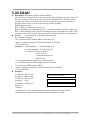
3.6 $AA6(ID)
7521/7522/7522A/7523/7524/7527
DESCRIPTION: SET THE ID-STRING OF COM-1/3/4/5/6/7/8, MAX.=50 CHARACTERS
Syntax: $AA6(ID)[chk](CrLf)
$ is a delimiter character
AA=2-character HEX module address, from 00 to FF
(ID): ID-string, max. 50 characters.
[chk]=2-character checksum, if checksum disabled no [chk]
(CrLf)=End-Char
Response: valid command
!AA[chk](CrLf)
invalid command
?AA[chk](CrLf)
no response :
syntax error or communication error or address error
! is a delimiter character indicating a valid command
? is a delimiter character indicating an invalid command
AA=2-character HEX module address
[chk]=2-character checksum, if checksum disabled no [chk]
(CrLf)=End-Char
Example: (Assume the AA of 7523 is 01)
command: $016Temperature1(CrLf)
ID of RS232(COM1) is Temperature1
response : !01(CrLf)
command: $026HP34401A-1(CrLf)
ID of RS232(COM3) is HP34401A-1
response : !02(CrLf)
command: $036HP34401A-2(CrLf)
ID of RS232(COM4) is HP34401A-2
response : !03(CrLf)
ADDRESS MAPPING: REFER TO PAGE 51
7521/7522/7522A/7523/7524/7527 Software User’s Manual (Rev. 2.1, Jul/2005, 7PS-000-21) ----- 57
3.7 $AA7
7521/7522/7522A/7523/7524/7527
DESCRIPTION: READ THE ID=-STRING OF COM-1/3/4/5/6/7/8
Syntax: $AA7[chk](CrLf)
$ is a delimiter character
AA=2-character HEX module address, from 00 to FF
[chk]=2-character checksum, if checksum disabled no [chk]
(CrLf)=End-Char
Response: valid command
!AA(ID)[chk](CrLf)
invalid command ?AA[chk](CrLf)
no response : syntax error or communication error or address error
(ID): ID-string, max. 50 characters.
! is a delimiter character indicating a valid command
? is a delimiter character indicating an invalid command
AA=2-character HEX module address
[chk]=2-character checksum, if checksum disabled no [chk]
(CrLf)=End-Char
Example: (Assume the AA of 7523 is 01)
command: $017(CrLf)
ID of RS232(COM1) is Temperature1
response : !01Temperature1(CrLf)
command: $027(CrLf)
ID of RS232(COM3) is HP34401A-1
response : !02HP34401A-1(CrLf)
command: $037(CrLf)
ID of RS232(COM4) is HP34401A-2
response : !03HP34401A-2(CrLf)
ADDRESS MAPPING: REFER TO PAGE 51
7521/7522/7522A/7523/7524/7527 Software User’s Manual (Rev. 2.1, Jul/2005, 7PS-000-21) ----- 58
3.8
$AAC[delimiter]
7521/7522/7522A/7523/7524/7527
DESCRIPTION: READ/SET THE DELIMITER OF COM-1/3/4/5/6/7/8
$AAC[chk](CrLf): Read the delimiter of COM-1/3/4 stored in EEPROM
$AAC(delimiter)[chk](CrLf): Set the delimiter of COM-1/3/4
Syntax: $AAC[delimiter][chk](CrLf)
$ is a delimiter character
AA=2-character HEX module address, from 00 to FF
[delimiter]: default delimiter is :
[chk]=2-character checksum, if checksum disabled no [chk]
(CrLf)=End-Char
Response: valid command
!AA[delimiter][chk](CrLf)
invalid command
?AA[chk](CrLf)
no response :
syntax error or communication error or address error
! is a delimiter character indicating a valid command
? is a delimiter character indicating an invalid command
AA=2-character HEX module address
[chk]=2-character checksum, if checksum disabled no [chk]
(CrLf)=End-Char
Example: (Assume the AA of 7523 is 01)
command: $01C(CrLf)
Reads the delimiter of RS232(COM2) :
response : !01:(CrLf)
command: $02C(CrLf)
Reads the delimiter of RS232(COM3) :
response : !02:(CrLf)
command: $03C*(CrLf)
Changes the delimiter of RS232(COM4) *
response : !03(CrLf)
ADDRESS MAPPING: REFER TO PAGE 51
Note1: The delimiter of COM1/3/4/5/6/7/8 can be different.
Note 2: The default delimiter is :
Note 3: the delimiter cannot be $, ~, #, @, %, CR & LF
7521/7522/7522A/7523/7524/7527 Software User’s Manual (Rev. 2.1, Jul/2005, 7PS-000-21) ----- 59
3.9
$AAD
7521/7522/7522A/7523/7524/7527
DESCRIPTION: READ THE DELIMITER OF COM-1/3/4/5/6/7/8
Syntax: $AAD[chk](CrLf)
$ is a delimiter character
AA=2-character HEX module address, from 00 to FF
[chk]=2-character checksum, if checksum disabled no [chk]
(CrLf)=End-Char
Response: valid command
!AA(delimiter)[chk](CrLf)
invalid command
?AA[chk](CrLf)
no response :
syntax error or communication error or address error
(delimiter): default delimiter is :
! is a delimiter character indicating a valid command
? is a delimiter character indicating an invalid command
AA=2-character HEX module address
[chk]=2-character checksum, if checksum disabled no [chk]
(CrLf)=End-Char
Example: (Assume the AA of 7523 is 01)
command: $01D(CrLf)
Reads the delimiter of RS232(COM1) :
response : !01:(CrLf)
command: $02D(CrLf)
Reads the delimiter of RS232(COM3) :
response : !02:(CrLf)
command: $03D(CrLf)
Reads the delimiter of RS232(COM4) *
response : !03*(CrLf)
ADDRESS MAPPING: REFER TO PAGE 51
Note1: The delimiter of COM1/3/4/5/6/7/8 can be different.
Note 2: The default delimiter is :
7521/7522/7522A/7523/7524/7527 Software User’s Manual (Rev. 2.1, Jul/2005, 7PS-000-21) ----- 60
3.10
(delimiter)AA(bypass)
7521/7522/7522A/7522
/7524/7527
DESCRIPTION: BYPASS DATA-STRING TO COM-1/3/4/5/6/7/8
Syntax: (delimiter)AA(bypass)[chk](CrLf)
AA=2-character HEX module address, from 00 to FF
(bypass): data-string send to COM-1/3/4
[chk]=2-character checksum, if checksum disabled no [chk]
(CrLf)=End-Char
Response: valid command
!AA[chk](CrLf)
invalid command
?AA[chk](CrLf)
no response :
syntax error or communication error or address error
! is a delimiter character indicating a valid command
? is a delimiter character indicating an invalid command
AA=2-character HEX module address
[chk]=2-character checksum, if checksum disabled no [chk]
(CrLf)=End-Char
Example: (Assume the AA of 7523 is 01, the delimiters for COM1/3/4 are :/;/*)
command: :01abcde(CrLf)
Sends abcde to COM1
response : !01(CrLf)
command: ;02123456789(CrLf)
Sends 123456789 to COM3
response : !02(CrLf)
command: *03test(CrLf)
Sends test to COM4
response : !03(CrLf)
ADDRESS MAPPING: REFER TO PAGE 51
7521/7522/7522A/7523/7524/7527 Software User’s Manual (Rev. 2.1, Jul/2005, 7PS-000-21) ----- 61
3.11
$AAK[checksum]
7521/7522/7522A/7523/7524/7527
DESCRIPTION: READ/SET THE CHECKSUM-STATUS
$AAK[chk](CrLf): Read the checksum-status stored in EEPROM
$AAK(checksum )[chk](CrLf): Set the checksum-status
Syntax: $AAK[checksum][chk](CrLf)
$ is a delimiter character
AA=2-character HEX module address, from 00 to FF
[checksum]: 0= checksum disable, 1= checksum enable
[chk]=2-character checksum, if checksum disabled no [chk]
(CrLf)=End-Char
Response: valid command
!AA[checksum][chk](CrLf)
invalid command
?AA[chk](CrLf)
no response :
syntax error or communication error or address error
! is a delimiter character indicating a valid command
? is a delimiter character indicating an invalid command
AA=2-character HEX module address
[chk]=2-character checksum, if checksum disabled no [chk]
(CrLf)=End-Char
Example: (Assume the AA of 7523 is 01, the other AA of 7523 is 04)
command: $01K0(CrLf)
Disables checksum
response : !01(CrLf)
command: $04K(CrLf)
The checksum is enabled
response : !041(CrLf)
Note: the checksum enable/disable is valid to COM2 only.
7521/7522/7522A/7523/7524/7527 Software User’s Manual (Rev. 2.1, Jul/2005, 7PS-000-21) ----- 62
3.12
$AATN[CrLfMode]
7521/7522/7522A/7523/7524/7527
DESCRIPTION: READ/SET THE END-CHAR OF COMMAND STRING
$AATN[chk](CrLf): Read the end-char of command string stored in EEPROM
$AATN(CrLfMode)[chk](CrLf): Set the end-char of command string
Syntax: $AATN[CrLfMode][chk](CrLf)
$ is a delimiter character
AA=2-character HEX module address, from 00 to FF
N=0 Read/Set the parity-bit of RS485, N=1 Read/Set the parity-bit of RS232
(CrLfMode):
0 (CrLf)=0x0D
1 (CrLf)=0x0D+0x0A
2 (CrLf)=0x0A
3 (CrLf)=0x0A+0x0D
4. No end-char
[chk]=2-character checksum, if checksum disabled no [chk]
(CrLf)=End-Char
Response: valid command
!AA[data-bit][chk](CrLf)
invalid command
?AA[chk](CrLf)
no response :
syntax error or communication error or address error
! is a delimiter character indicating a valid command
? is a delimiter character indicating an invalid command
AA=2-character HEX module address
[chk]=2-character checksum, if checksum disabled no [chk]
(CrLf)=End-Char
Example: (Assume the AA of 7523 is 01)
command: $01T0(CrLf)
The end-char of COM2 is no end character
response : !014(CrLf)
command: $01T1(CrLf)
The end-char of COM1 is 0x0D+0x0A
response : !011(CrLf)
command: $02T1(CrLf)
The end-char of COM3 is 0x0A
response : !022(CrLf)
command: $03T1(CrLf)
The end-char of COM4 is 0x0A+0x0D
response : !033(CrLf)
ADDRESS MAPPING: REFER TO PAGE 51
Note: the default CrLfMode = 4
the default (CrLf)=NONE for all port.
7521/7522/7522A/7523/7524/7527 Software User’s Manual (Rev. 2.1, Jul/2005, 7PS-000-21) ----- 63
3.13
7521/7522/7522A/7523/7524/7527
$AAW
DESCRIPTION: READ THE CTS-STATUS OF COM-1/3
SYNTAX: $AAW[CHK](CRLF)
$ is a delimiter character
AA=2-character HEX module address, from 00 to FF
[chk]=2-character checksum, if checksum disabled no [chk]
(CrLf)=End-Char
Response: valid command
!AAS[chk](CrLf)
invalid command
?AA[chk](CrLf)
no response :
syntax error or communication error or address error
S: 0 CTS is inactive now, 1 CTS is active_HIGH now
! is a delimiter character indicating a valid command
? is a delimiter character indicating an invalid command
AA=2-character HEX module address
[chk]=2-character checksum, if checksum disabled no [chk]
(CrLf)=End-Char
Example: (Assume the AA of 7523 is 01)
command: $01W(CrLf)
The CTS of COM1 is inactive now.
response : !010(CrLf)
command: $02W(CrLf)
The CTS of COM3 is active-HIGH now.
response : !021(CrLf)
ADDRESS MAPPING FOR CTS-STATUS:
COM1(RS232)
COM3(RS232)
7521
AA
N/A
7522
AA
AA+1
7522A
AA
N/A
7523
AA
AA+1
7524
AA
AA+1
7527
AA
AA+1
Note1: The CTS-status is valid for COM1 & COM3
7521/7522/7522A/7523/7524/7527 Software User’s Manual (Rev. 2.1, Jul/2005, 7PS-000-21) ----- 64
3.14
7521/7522/7522A/7523/7524/7527
$AAXV
DESCRIPTION: SET THE RTS-STATE OF COM-1/3
Syntax: $AAXV[chk](CrLf)
$ is a delimiter character
AA=2-character HEX module address, from 00 to FF
V: 0 set RTS inactive, 1 set RTS to active_HIGH state
[chk]=2-character checksum, if checksum disabled no [chk]
(CrLf)=End-Char
Response: valid command
!AA[chk](CrLf)
invalid command
?AA[chk](CrLf)
no response :
syntax error or communication error or address error
! is a delimiter character indicating a valid command
? is a delimiter character indicating an invalid command
AA=2-character HEX module address
[chk]=2-character checksum, if checksum disabled no [chk]
(CrLf)=End-Char
Example: (Assume the AA of 7523 is 01)
command: $01X0(CrLf)
Sets the RTS of COM1 to inactive state
response : !01(CrLf)
command: $02X1(CrLf)
Sets the RTS of COM3 to active-HIGH state
response : !02(CrLf)
ADDRESS MAPPING FOR RTS-STATE:
COM1(RS232)
COM3(RS232)
7521
AA
N/A
7522
AA
AA+1
7522A
AA
N/A
7523
AA
AA+1
7524
AA
AA+1
7527
AA
AA+1
Note1: The RTS-state is valid for COM1 & COM3
7521/7522/7522A/7523/7524/7527 Software User’s Manual (Rev. 2.1, Jul/2005, 7PS-000-21) ----- 65
3.15
7521/7522/7522A/7523/7524/7527
$AAYN
DESCRIPTION: READ THE ONBOARD DI-1/2/3
Syntax: $AAYN[chk](CrLf)
$ is a delimiter character
AA=2-character HEX module address, from 00 to FF
N: 1 read DI1, 2 read DI2, 3 read DI3
[chk]=2-character checksum, if checksum disabled no [chk]
(CrLf)=End-Char
Response: valid command
!AAS[chk](CrLf)
invalid command
?AA[chk](CrLf)
no response :
syntax error or communication error or address error
! is a delimiter character indicating a valid command
? is a delimiter character indicating an invalid command
AA=2-character HEX module address
S=0 DI=Low, 1 DI=High (DI floating will get High)
[chk]=2-character checksum, if checksum disabled no [chk]
(CrLf)=End-Char
Example: (Assume the AA of 7521 is 01)
command: $01Y1(CrLf)
DI1=Low
response : !010(CrLf)
command: $01Y2(CrLf)
DI2=High
response : !011(CrLf)
command: $01Y3(CrLf)
DI3=Low
response : !010(CrLf)
DI MAPPING TABLE:
DI1
DI2
DI3
7521
YES
YES
YES
7522
YES
YES
YES
7522A
YES
NO
NO
7523
YES
YES
NO
7524
YES
NO
NO
7527
YES
NO
NO
7521/7522/7522A/7523/7524/7527 Software User’s Manual (Rev. 2.1, Jul/2005, 7PS-000-21) ----- 66
3.16
7521/7522/7522A/7524/7527
$AAZNV
DESCRIPTION: WRITE TO ONBOARD DO-1/2/3
Syntax: $AAZNV[chk](CrLf)
$ is a delimiter character
AA=2-character HEX module address, from 00 to FF
N: 1 write DO1, 2 write DO2, 3 write DO3
V: 0 set D/O off, 1 set D/O on
[chk]=2-character checksum, if checksum disabled no [chk]
(CrLf)=End-Char
Response: valid command
!AA[chk](CrLf)
invalid command
?AA[chk](CrLf)
no response :
syntax error or communication error or address error
! is a delimiter character indicating a valid command
? is a delimiter character indicating an invalid command
AA=2-character HEX module address
[chk]=2-character checksum, if checksum disabled no [chk]
(CrLf)=End-Char
Example: (Assume the AA of 7521 is 01)
command: $01Z10(CrLf)
Set DO1=OFF
response : !01(CrLf)
command: $01Z21(CrLf)
Set DO2=ON
response : !01(CrLf)
command: $01Z30(CrLf)
Set DO3=OFF
response : !01(CrLf)
DO MAPPING TABLE:
DO1
DO2
DO3
7521
YES
YES
YES
7522
YES
NO
NO
7522A
YES
NO
NO
7523
NO
NO
NO
7524
YES
NO
NO
7527
YES
NO
NO
NOTE: IF THE HOST FAILS, THE ~AAZNV COMMAND WILL BE IGNORED. AND THE RESPONSE
STRING WILL BE !
(In normal situation, the response string will be !AA)
7521/7522/7522A/7523/7524/7527 Software User’s Manual (Rev. 2.1, Jul/2005, 7PS-000-21) ----- 67
3.17
#**
7521/7522/7522A/7523/7524/7527
Description: Order all input modules, digital and analog, sample all their input data
immediately and store this data in the internal register of the module. Later the host
computer can read this data one by one by using the command $AA4, read
synchronized data.
Syntax: #**[chk](CrLf)
# is a delimiter character
* is a command character
[chk]=2-character checksum, if checksum disabled no [chk]
(CrLf)=End-Char
Response: no response
Example:
Orders all modules to perform synchronized
command: #**(CrLf)
sampling
response:
no response
command: $014(CrLf)
DI1=DI2=DI3=1
response:
!0117(CrLf)
command: $024(CrLf)
DI1=DI2=1, DI3=0
response:
!0213(CrLf)
command: $034(CrLf)
DI1=1, DI2=DI3=0
response:
!0311(CrLf)
NOTE : What’s “synchronize sampling” ?
The host computer can send only one command string at a time. If there are two
modules, the host computer must send and receive the module-1 commands then the
module-2 commands. So there is a time delay between these two commands. The
“synchronize sampling” command is designed for all input modules. When receiving
#**[CrLf], synchronized sampling command, all input modules in the RS-485 network
will perform the input function at the same time and store these values into the
module’s memory. Then the host computer can send out the “$AA4, read synchronize
data” command to read this data separately.
7521/7522/7522A/7523/7524/7527 Software User’s Manual (Rev. 2.1, Jul/2005, 7PS-000-21) ----- 68
3.18
$AA4
7521/7522/7522A/7523/7524/7527
Description : Reads the synchronized data.
Syntax : $AA4[chk](CrLf)
$ is a delimiter character
AA=2-character HEX module address, from 00 to FF
[chk]=2-character checksum, if checksum disabled no [chk]
(CrLf)=End-Char
Response : valid command
!AASV[chk](CrLf)
invalid command
?AA[chk](CrLf)
no response : syntax error or communication error or address error
! is a delimiter character indicating a valid command
? is a delimiter character indicating an invalid command
AA=2-character HEX module address
S=1=first reading
=0=not first reading
V: D0=DI1, D1=DI2, D2=DI3
[chk]=2-character checksum, if checksum disabled no [chk]
(CrLf)=End-Char
Example :
command: #**(CrLf)
response:
no response
command: $014(CrLf)
DI1=DI2=DI3=1
response:
!0117(CrLf)
command: $024(CrLf)
DI1=DI2=1, DI3=0
response:
!0213(CrLf)
command: $034(CrLf)
DI1=1, DI2=DI3=0
response:
!0311(CrLf)
NOTE : What’s “synchronize sampling” ?
The host computer can send only one command string at a time. If there are two
modules, the host computer must send and receive the module-1 commands then the
module-2 commands. So there is a time delay between these two commands. The
“synchronize sampling” command is designed for all input modules. When receiving
#**[CrLd], synchronized sampling command, all input modules in the RS-485 network
will perform the input function at the same time and store these values into the
module’s memory. Then the host computer can send out the “$AA4, read synchronize
data” command to read this data separately.
7521/7522/7522A/7523/7524/7527 Software User’s Manual (Rev. 2.1, Jul/2005, 7PS-000-21) ----- 69
3.19
$AA5
7521/7522/7522A/7523/7524/7527
Description: Resets status read back. This is the only command to detect the module hardware
watchdog failure. If the module is down, the module hardware watchdog circuit will reset this
module. This reset will cause the output state of the module to go to their start-value. The
start-value may be different from those output-values before module reset. Therefore the user
needs to send an output command again to the module for maintaining the same output state
before and after module watchdog reset.
Syntax: $AA5[chk](CrLf)
$ is a delimiter character
AA=2-character HEX module address, from 00 to FF
[chk]=2-character checksum, if checksum disabled no [chk]
(CrLf)=End-Char
Response : valid command
!AAS[chk](CrLf)
invalid command
?AA[chk](CrLf)
no response : syntax error or communication error or address error
! is a delimiter character indicating a valid command
? is a delimiter character indicating an invalid command
S = 0, it has not been reset since the last reset status read
1, it has been reset since the last reset status read
[chk]=2-character checksum, if checksum disabled no [chk]
(CrLf)=End-Char
Note: When first powering-on, the user should read the module once and will find that
S=1. Then the user should read the module continually and find that S=0. If S is
changed to 1, this module has been reset by module hardware watchdog circuit at
least once. And all output is going to its start-value now. Therefore the user needs to
send an output command again to control all output values to desired states.
Example:
It is first time power-on reset
command: $015(CrLf)
response : !011(CrLf)
command: $015(CrLf)
It is normal
response : !010(CrLf)
It is normal
command: $015(CrLf)
response : !010(CrLf)
This module has been reset by module
command: $015(CrLf)
hardware watchdog. Therefore all output is
response : !011(CrLf)
going to its start-values now.
7521/7522/7522A/7523/7524/7527 Software User’s Manual (Rev. 2.1, Jul/2005, 7PS-000-21) ----- 70
3.20
$AAF
7521/7522/7522A/7523/7524/7527
Description : Reads the firmware version number.
Syntax : $AAF[chk](CrLf)
$ is a delimiter character
AA=2-character HEX module address, from 00 to FF
[chk]=2-character checksum, if checksum disabled no [chk]
(CrLf)=End-Char
Response : valid command
!AA(number)[chk](CrLf)
invalid command
?AA[chk](CrLf)
no response : syntax error or communication error or address error
! is a delimiter character indicating a valid command
? is a delimiter character indicating an invalid command
AA=2-character HEX module address
number=4-character for version number
[chk]=2-character checksum, if checksum disabled no [chk]
(CrLf)=End-Char
Example:
command: $01F(CrLf)
module 01 version 2.0
response : !01A2.0(CrLf)
command: $02F(CrLf)
module 02 version 3.0
response : !02A3.0(CrLf)
3.21
$AAM
7521/7522/7522A/7523/7524/7527
Description : Reads the module name.
Syntax : $AAM[chk](CrLf)
$ is a delimiter character
AA=2-character HEX module address, from 00 to FF
[chk]=2-character checksum, if checksum disabled no [chk]
(CrLf)=End-Char
Response : valid command
!AA(name)[chk](CrLf)
invalid command
?AA[chk](CrLf)
no response : syntax error or communication error or address error
! is a delimiter character indicating a valid command
? is a delimiter character indicating an invalid command
AA=2-character HEX module address
name=4-character or 5-character for module name
[chk]=2-character checksum, if checksum disabled no [chk]
(CrLf)=End-Char
Example:
name of module 01 is 7521
command: $01F(CrLf)
response : !017521(CrLf)
name of module 02 is 7523
command: $02F(CrLf)
response : !027523(CrLf)
7521/7522/7522A/7523/7524/7527 Software User’s Manual (Rev. 2.1, Jul/2005, 7PS-000-21) ----- 71
3.22
$AA2
7521/7522/7522A/7523/7524/7527
Description : Reads the configuration code of COM2(RS485) stored in EEPROM
Syntax : $AA2[chk](cr)
$ is a delimiter character
AA=2-character HEX module address, from 00 to FF
[chk]=2-character checksum, if checksum disabled no [chk]
(cr)=0x0D
Response : valid command
!AA40BDPK[chk](cr),
invalid command
?AA[chk](cr)
no response : syntax error or communication error or address error
! is a delimiter character indicating a valid command
? is a delimiter character indicating an invalid command
AA=2-character HEX module address
B=short-code for baud rate, refer to Sec. 3.2
D=data-bit, refer to Sec. 3.3
P=party-bit, refer to Sec. 3.4
K=checksum status, refer to Sec. 3.5
[chk]=2-character checksum, if checksum disabled no [chk]
(cr)=0x0D
Example: (assume DI1/INIT*=GND)
command:
response :
$002(cr)
!01406800(cr)
command:
response :
$002(cr)
!0240A801(cr)
address 01 is 7521 series module, 9600 BPS,
N81, checksum disable
checksum disable
address 02 is 7521 series module, 115200
BPS, N81, checksum enable
7521/7522/7522A/7523/7524/7527 Software User’s Manual (Rev. 2.1, Jul/2005, 7PS-000-21) ----- 72
3.23
~**
7521/7522/7522A/7523/7524/7527
Description : Host computer sends this command to tell all modules “Host is OK”.
Syntax : ~**[chk](CrLf)
~ is a delimiter character
[chk]=2-character checksum, if checksum disabled no [chk]
(CrLf)=End-Char
Response : no response
Example:
command: ~**(CrLf)
response : No Response
3.24
~AA0
7521/7522/7522A/7523/7524/7527
Description : Reads the module status. The module status will be latched until ~AA1
command is sent. If the module status=0x04, all output commands will be ignored.
Syntax : ~AA0[chk](CrLf)
~ is a delimiter character
AA=2-character HEX module address, from 00 to FF
[chk]=2-character checksum, if checksum disabled no [chk]
(CrLf)=End-Char
Response : valid command
!AASS[chk](CrLf)
invalid command
?AA[chk](CrLf)
no response : syntax error or communication error or address error
! is a delimiter character indicating a valid command
? is a delimiter character indicating an invalid command
AA=2-character HEX module address
SS=2-character HEX status value as following:
Bit_0 = reserved
Bit_1 = reserved
Bit_2 = 0 OK
1 host watchdog failure
[chk]=2-character checksum, if checksum disabled no [chk]
(CrLf)=End-Char
Example:
command:
response :
~010(CrLf)
!0100(CrLf)
Status of module 01 is OK
command:
response :
~020(CrLf)
!0204(CrLf)
Status of module 02 is “host watchdog
failure” HOST is down now
7521/7522/7522A/7523/7524/7527 Software User’s Manual (Rev. 2.1, Jul/2005, 7PS-000-21) ----- 73
3.25
~AA1
7521/7522/7522A/7523/7524/7527
Description : Resets module status. The module status will be latched until ~AA1
command is sent. If the module status=0x04, all output commands will be ignored.
Therefore the user should read the module status first to make sure that the module
status is 0. If the module status is not 0, only the ~AA1 command can clear the module
status.
Syntax : ~AA1[chk](CrLf)
~ is a delimiter character
AA=2-character HEX module address, from 00 to FF
[chk]=2-character checksum, if checksum disabled no [chk]
(CrLf)=End-Char
Response : valid command
!AA[chk](CrLf)
invalid command
?AA[chk](CrLf)
no response : syntax error or communication error or address error
! is a delimiter character indicating a valid command
? is a delimiter character indicating an invalid command
AA=2-character HEX module address
[chk]=2-character checksum, if checksum disabled no [chk]
(CrLf)=End-Char
Example:
module status=0x04 host is down
command: ~010(CrLf)
response : !0104(CrLf)
Output command is ignored
command: $01211(CrLf)
response : !(CrLf)
command: ~011(CrLf)
clears module status
response : !01(CrLf)
command: ~010(CrLf)
module status=0x00
response : !0100(CrLf)
command: $01211(CrLf)
Output command is OK
response : >(CrLf)
7521 Series Module Status Comparison:
(1) module hardware watchdog reset
all D/O goes to their start-values
module status no change
accept host D/O command to change D/O state
(2) host software watchdog failure
all D/O goes to their save-value
module status=04 host watchdog failure
ignores all host D/O command until module status is cleared to 0 by ~AA1 command
7521/7522/7522A/7523/7524/7527 Software User’s Manual (Rev. 2.1, Jul/2005, 7PS-000-21) ----- 74
3.26
~AA2
7521/7522/7522A/7523/7524/7527
Description : Reads the status of host watchdog and the host watchdog timer value.
The host watchdog timer is designed for software host watchdog. When the software
host watchdog is enabled, the host must send ~**, HOST is OK command, to all
modules before the timer is up. When the ~** command is received, the host
watchdog timer is reset and restarted. Use ~AA3ETT to enable/disable/setting the host
watchdog timer.
Syntax : ~AA2[chk](CrLf)
~ is a delimiter character
AA=2-character HEX module address, from 00 to FF
[chk]=2-character checksum, if checksum disabled no [chk]
(CrLf)=End-Char
Response : valid command
!AASTT[chk](CrLf)
invalid command
?AA[chk](CrLf)
no response : syntax error or communication error or address error
! is a delimiter character indicating a valid command
? is a delimiter character indicating an invalid command
AA=2-character HEX module address
S=0: host watchdog is disable, S=1:host watchdog is enable
TT=2-character HEX value, from 00 to FF, unit=0.1 second
[chk]=2-character checksum, if checksum disabled no [chk]
(CrLf)=End-Char
Example:
Host watchdog timer of module 01 is
disabled
command: ~012(CrLf)
response : !01000(CrLf)
host watchdog timer of module 02 is enabled
command: ~022(CrLf)
and =0.1*10 =1 second.
response : !0210A(CrLf)
7521 Series Module Status Comparison:
(1) module hardware watchdog reset
all D/O goes to their start-values
module status no change
accept host D/O command to change D/O state
(2) host software watchdog failure
all D/O goes to their save-values
module status=04 host watchdog failure
ignores all host D/O command until module status is cleared to 0 by ~AA1 command
7521/7522/7522A/7523/7524/7527 Software User’s Manual (Rev. 2.1, Jul/2005, 7PS-000-21) ----- 75
3.27
~AA3ETT
7521/7522/7522A/7523/7524/7527
Description : Enables/disables the host watchdog timer value. The host watchdog
timer is designed for software host watchdog. When the software host watchdog is
enabled, the host must send ~**, HOST is OK command, to all modules before the
timer is up. When the ~** command is received, the host watchdog timer is reset and
restarted. Use ~AA2 to read the host watchdog status & value.
Syntax :~AA3ETT[chk](CrLf)
~ is a delimiter character
AA=2-character HEX module address, from 00 to FF
E=0 is disable and 1 is enable
TT=2-character HEX value, from 00 to FF, unit=0.1 second
[chk]=2-character checksum, if checksum disabled no [chk]
(CrLf)=End-Char
Response : valid command
!AA[chk](CrLf)
invalid command
?AA[chk](CrLf)
no response : syntax error or communication error or address error
! is a delimiter character indicating a valid command
? is a delimiter character indicating an invalid command
AA=2-character HEX module address
[chk]=2-character checksum, if checksum disabled no [chk]
(CrLf)=End-Char
Example:
disables host watchdog timer of module 01
command: ~013000(CrLf)
response : !01(CrLf)
command:
response :
~02310A(CrLf)
!02(CrLf)
host watchdog timer of module 02 is enabled
and equal to 0.1*10 =1 second.
7521/7522/7522A/7523/7524/7527 Software User’s Manual (Rev. 2.1, Jul/2005, 7PS-000-21) ----- 76
3.28
~AA4P & ~AA4S
7521/7522/7522A/7524/7527
Description : Reads power-on/safe value.
(1) When the module is first powered-on, all output channels will go to their poweron value.
(2) When the module is down, the hardware module watchdog will reset the module
and all output channels will also go to their power-on value. These power-on
values may be different from old values before the module was reset.
Therefore the user must send out a new output command to change all output to
their desired states.
(3) When the host watchdog is enabled and the host is down, all output will go to
their safe values and module status will change to 0x04. If the module status is
0x04, all output commands will be ignored before the module status is cleard by
~AA1 command. Therefore the user must send ~AA1 command first, then send
out a new output command to change all output to their desired states.
Syntax :
~AA4P[chk](CrLf) read power-on value
~AA4S[chk](CrLf) read safe value
~ is a delimiter character
AA=2-character HEX module address, from 00 to FF
[chk]=2-character checksum, if checksum disabled no [chk]
(CrLf)=End-Char
Response : valid command
!AAV[chk](CrLf) for I-7042
invalid command
?AA[chk](CrLf)
no response : syntax error or communication error or address error
! is a delimiter character indicating a valid command
? is a delimiter character indicating an invalid command
AA=2-character HEX module address
V: D0=DO0, D1=DO1, D2=DO3
[chk]=2-character checksum, if checksum disabled no [chk]
(CrLf)=End-Char
Example:
Power-on value is all DO-1/2/3 ON
command: ~014P(CrLf)
response : !017(CrLf)
command:
response :
~024S(CrLf)
!020(CrLf)
Safe value is all DO-1/2/3 OFF
7521/7522/7522A/7523/7524/7527 Software User’s Manual (Rev. 2.1, Jul/2005, 7PS-000-21) ----- 77
3.29
~AA5P & ~AA5S
7521/7522/7522A/7524/7527
Description : Sets current state of digital output as power-on/safe value.
(1) When the module is first powered-on, all output channels will go to their poweron value.
(2) When the module is down, the hardware module watchdog will reset the module
and all output channels will also go to their power-on value. These power-on
values may be different from old values before the module was reset.
Therefore the user must send out a new output command to change all output to
their desired states.
(3) When the host watchdog is enabled and the host is down, all output will go to
their safe values and module status will change to 0x04. If the module status is
0x04, all output command will be ignored before the module status is clear by
~AA1 command. Therefore the user must send ~AA1 command first, then send
out a new output command to change all output to their desired states.
Syntax :
~AA5P[chk](CrLf) set power-on value
~AA5S[chk](CrLf) set safe value
~ is a delimiter character
AA=2-character HEX module address, from 00 to FF
[chk]=2-character checksum, if checksum disabled no [chk]
(CrLf)=End-Char
Response : valid command
!AAV[chk](CrLf)
invalid command
?AA[chk](CrLf)
no response : syntax error or communication error or address error
! is a delimiter character indicating a valid command
? is a delimiter character indicating an invalid command
AA=2-character HEX module address
V: D0=DO0, D1=DO1, D2=DO3
[chk]=2-character checksum, if checksum disabled no [chk]
(CrLf)=End-Char
Example:
Power-on value is all DO-1/2/3 ON
command: ~015P(CrLf)
response : !017(CrLf)
command:
response :
~025S(CrLf)
!020(CrLf)
Power-on value is all DO-1/2/3 OFF
7521/7522/7522A/7523/7524/7527 Software User’s Manual (Rev. 2.1, Jul/2005, 7PS-000-21) ----- 78
3.30 $AAU
Description: Read data from the COM port buffer.
Any 232 device should obey the rules of request-reply constitution. In other word, 232
devices are passive. If they have not received any commands, they will not send any
message out. However, since the active device frequently appear, our controller is
designed with a buffer to receive these message in this situation.
Buffer operation rules:
Rule 1: buffer is enabled after power-on.
Rule 2: (delimiter) AA command (ref. Sec.3.10) disables buffer operation of that port
Rule 3: after disabling buffer, the first incoming message will transfer to COM2. Then
controller waits for 10 seconds. If no message has arrived, the buffer is enabled again.
Syntax:
$AAU[chk](CrLf) read first data in buffer
$is a delimiter character
AA=2-character HEX module address, from 00 to FF
[chk]=2-character checksum, if checksum disable no [chk]
(CrLf)=End-Char
Response : valid command
(data)[chk](CrLf)
invalid command
?AA[chk](CrLf)
no response : buffer is empty or
syntax error or
communication error or
address error
! is a delimiter character indicating a valid command
? is a delimiter character indicating an invalid command
AA=2-character HEX module address
[chk]=2-character checksum, if checksum disabled no [chk]
(CrLf)=End-Char
Example:
Command: $01U(CrLf)
Retrieves “data1” from buffer
Response: data1(CrLf)
Command: $01U(CrLf)
Retrieves another data: “data2” from buffer
Response: data2
Command: $02U(CrLf)
No data is in buffer.
Response:
Warning:
(1)Change CrLf mode will corrupt the integrity of unread data in the buffer
(2)Repeat this command several times to ensure the buffer is empty.
7521/7522/7522A/7523/7524/7527 Software User’s Manual (Rev. 2.1, Jul/2005, 7PS-000-21) ----- 79
7522A only
3.31 $AAL(data)
Description: Write to expansion board DO 0/1/2/3
Syntax: $AALbbbb[chk](CrLf), $AALcb[chk](CrLf), $AALh[chk](CrLf)
$ is a delimiter character
AA=2-character HEX module address, from 00 to FF
b: 1 set to On, 0 set to Off
c: 0 DO0, 1 DO1, 2 DO2, 3 DO3
h: 4-bit hex value of DO. DO0 is at LSB. Valid value is 0~9, a~f, A~F
[chk]=2-character checksum, if checksum disabled no [chk]
(CrLf)=End-Char
Response: valid command
!AA[chk](CrLf)
invalid command
?AA[chk](CrLf)
no response :
syntax error or communication error or address
error
! is a delimiter character indicating a valid command
? is a delimiter character indicating an invalid command
AA=2-character HEX module address
[chk]=2-character checksum, if checksum disabled no [chk]
(CrLf)=End-Char
Example: (Assume the AA of 7521 is 01)
command: $01L1000(CrLf)
Set DO3=ON, DO2,DO1,DO0=0
response : !01 08(CrLf)
command: $01L21(CrLf)
Set DO2=ON, other DOn are unchanged.
response : !01 0H(CrLf)
command: $01L30(CrLf)
Set DO3=OFF, other DOn are unchanged.
response : !01 0H(CrLf)
command: $01LE(CrLf)
Set DO0=OFF, DO1,DO2,DO3=ON
response : !01 0E(CrLf)
Note: If the host fails, the ~AAL command will be ignored. And the response string
will be ?AA (In normal situation, the response string will be !AA 0H)
PWR 24
DO0~3 25
28
GND 23
7521/7522/7522A/7523/7524/7527 Software User’s Manual (Rev. 2.1, Jul/2005, 7PS-000-21) ----- 80
7522A only
3.32 $AAR
Description: Read the expansion board DI-0/1/2/3
Syntax: $AAR[chk](CrLf)
$ is a delimiter character
AA=2-character HEX module address, from 00 to FF
[chk]=2-character checksum, if checksum disabled no [chk]
(CrLf)=End-Char
valid command
!AAN[N][chk](CrLf)
Response:
invalid command
?AA[chk](CrLf)
no response :
syntax error or communication error or address
error
! is a delimiter character indicating a valid command
? is a delimiter character indicating an invalid command
AA=2-character HEX module address
S=0 DI=Low, 1 DI=High (DI floating will get High)
[chk]=2-character checksum, if checksum disabled no [chk]
(CrLf)=End-Char
Example: (Assume the AA of 7521 is 01)
DIx(pin
DI019~22
pin 19
+20V
DI1 pin 20
DI2 pin 21
DI3 pin 22
command:
response :
$01R(CrLf)
!015(CrLf)
Not connected
-5V
DI3,DI1=low(0), DI2,DI0=high(1)
7521/7522/7522A/7523/7524/7527 Software User’s Manual (Rev. 2.1, Jul/2005, 7PS-000-21) ----- 81
4. Operational Principles & Application
Notes
4.1 DI1/INIT* Pin Operation Principles
The 7521 series modules contains an EEPROM to store configuration information. Therefore
it is difficult for the user to find out the status of the 7521 series modules. The steps to get the
configuration data stored in EEPROM are given as follows:
Stage 1: refer to Step1 ~ Step4 of Sec. 1.6
Stage 2: keyin 7521 & Enter-key to execute 7521.exe (DI1/INIT* is connected to GND now)
Stage 3: send command to 7521 for configuration reading
Then the 7521 series modules will go to the factory default setting without changing the
EEPROM data. The factory default setting is given as following:
address
= 00
baud rate
= 9600
checksum
= DISABLE
data format = 1 start + 8 data bits + 1 stop bit ( N 8 1 )
If disconnecting the DI1/INIT*_pin and GND_pin, the I_7000 module will auto configure
based on the EEPROM data. For the user, it is easy to find the EEPROM configuration data in
the default setting. The steps are shown as following:
Step 1 : power off and connect DI1/INIT*_pin to GND_pin
Step 2 : power on & refer to step1 ~ step4 of Sec. 1.6
Step 3: keyin 7521 & Enter-key to execute 7521.exe
Step 4 : send command string $00M[0x0D]
Step 5 : record the module name
Step 6 : send command string $00A[0x0D]
Step 7 : record the module address
Step 8 : send command string $00B[0x0D]
Step 9 : record the baud rate
Step 10 : send command string $00D[0x0D]
Step 11: record the data-bit
Step 12: send command string $00P[0x0D]
Step 13: record the parity-bit
Step 14: send command string $00K0[0x0D]
Step 15: record the checksum status
Step 16: power off and disconnect INIT*_pin and GND_pin
Step 17: power on, the 7521 series will work in the same status as your record
Note: step 6 to step 15 can be replaced by $002[0x0D] command
7521/7522/7522A/7523/7524/7527 Software User’s Manual (Rev. 2.1, Jul/2005, 7PS-000-21) ----- 82
4.2 D/O Operating Principles
(1)
(2)
(3)
(4)
(5)
The D/O of the 7521 series will go to their start-values after first powering
on.
The D/O output will change to desired state if the “$AAZNV” command is
received. Then, all the D/O will remain in the same states until next
“$AAZNV” command.
If the 7521 series is reset by the hardware watchdog, all D/O will go to
their power-on values immediately. These power-on values may be different
from the original states before reset. So the D/O states stored in Host-PC may
be different from real D/O states latched in the 7521 series. The Host-PC must
send the “$AAZNV” command to set these D/O to expected states.
The Host-PC can use “$AA5” command to detect the hardware watchdog
reset. Refer to Sec. 4.6 for more information. If the 7521 series is reset by
hardware watchdog, the Host-PC should send out “$AAZNV” command to
set all D/O to their expected states.
If the host watchdog fails, all the D/O will go to their safe-values
immediately and the module status will be set to 04. If the host computer
sends out “$AAZNV” to these modules now, the modules will ignore this
command and return “!” as warning information. The host can use the
“~AA1” command to clear the module status to 00, then the 7521 series
will accept the “$AAZNV” command again.
4.3 D/I Operating Principles
The I-7000 series D/I commands are given as follows:
(1) #**:
synchronized sampling, all modules will sample DI at the same
time
(2) $AA4: reads synchronized sampling data.
(3) $AAYN:
reads current state of D/I
The host computer can send only one command string at a time. If there are
two modules, the host computer must send and receive the module-1 commands
then the module-2 commands. So there is a time delay between these two
commands. The “synchronize sampling” command is designed for all input
modules. When receiving “#**[0x0D]”, synchronized sampling command, all the
input modules in the RS-485 network will perform the input function at the
same time and store these values into the module’s memory. Then the host
computer can send out the “$AA4, read synchronize data” command to read this
data separately
7521/7522/7522A/7523/7524/7527 Software User’s Manual (Rev. 2.1, Jul/2005, 7PS-000-21) ----- 83
4.4 Dual WatchDog Operation
Principle
All 7521 series modules are equipped with hardware module watchdog and
software host watchdog. The 7521 series are designed for industry applications,
therefore they are able to work in harsh envioronments. There is much couple noise
or energy transient in such an environment. The modules may shut down if this
noise is too large. The built-in hardware module watchdog can reset the
module if it is down due to too large a signal. Sometimes, even the host-PC may
shut down for hardware or software reasons. The software host watchdog can
monitor the status of host-PC. If the host-PC is down, all the output of the 7521
series modules will go to their predefined safe states for safety protection.
If the RS-485 network is open, all the host commands cannot be sent to
remote modules. This is very dangerous in real world application. The output
module of the 7521 series will force their output to go to their predefined safe state
for safety consideration if the host watchdog is enabled. This dual watchdog
feature will increase the system reliability a great deal.
4.5 Host WatchDog Applications Notes
The software host watchdog is designed to monitor the host computer. If the
host computer fails, the output of the 7521 series will automatically go to their safe
states to avoid unnecessary damage. The flow chart for the host computer is given
as follows.
Set Safe Value
Enable host watchdog
~**(CrLf)
Function 1
Send
to reset the host watchdog
timer before time out
Function n
7521/7522/7522A/7523/7524/7527 Software User’s Manual (Rev. 2.1, Jul/2005, 7PS-000-21) ----- 84
4.6 Module WatchDog Applications Notes
The “$AA5” command is designed to detect the module hardware watchdog
failure. If the module is down, the module hardware watchdog circuit will reset this
module. After reset the output state of module will go to their start-values. The
start-value may be different from those output-value before module reset.
Therefore the user needs to send output commands again to the module to maintain
the same output state before and after module watchdog reset.
The flow chart for module hardware watchdog failure detection is given as
follows.
Send “$AA5” and find S=1
S=1
All D/O will be in their startvalue now. Send “$AAZNV”
command to control D/O
modules to desire states.
Send “$AA5” and find S=?
S=0
Function 1
Function n
4.7 Source Code of the 7521/7522/7523
1. The source codes of the 7521 are given in the companion CD. User can
modify these files for individual applications. All source codes are welldocumented, so the user can change code easily. (Use BC to compile &
link)
2. There are two files, autoexec.bat & 7521.EXE, stored in the flash ROM of
the 7521. So the 7521.EXE will be executed after the power is supplied &
the DI1/INIT* pin is floating. It is also similar for the 7522 & 7523.
3. There are some ODM programs are provided for the 7521. Refer to the
readme.doc for more information. These ODM programs are given as
follows:
7521ODM1.c : 7521 + real time control D/IO
7521ODM2.c : 7521 + real time control AD&DA
7521ODM3.c : 7521 + real time control Event counter
7521ODM4.c : 7521 + real time control Sensor & Multiplex
7522ODM5.c : 7522 + real time monitor HP34401A & alarm control
More ODM functions will be available in the future.
7521/7522/7522A/7523/7524/7527 Software User’s Manual (Rev. 2.1, Jul/2005, 7PS-000-21) ----- 85