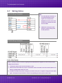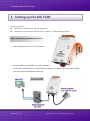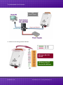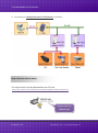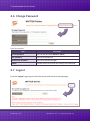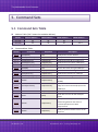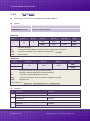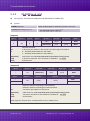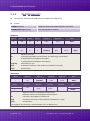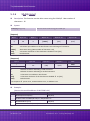
1
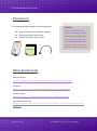
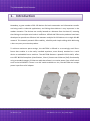
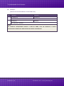
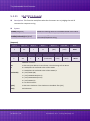
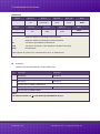
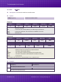
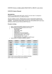
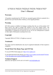
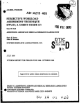
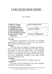
tM-752N Series User Manual Tiny Addressable Serial Converter Ver. 1.1.1/ Aug. 2014 SUPPORTS Module includes tM-7521 and tM-7522. WARRANTY All products manufactured by ICP DAS are warranted against defective materials for a period of one year from the date of delivery to the original purchaser. WARNING ICP DAS assumes no liability for damages consequent to the use of this product. ICP DAS reserves the right to change this manual at any time without notice. The information furnished by ICP DAS is believed to be accurate and reliable. However, no responsibility is assumed by ICP DAS for its use, nor for any infringements of patents or other rights of third parties resulting from its use. COPYRIGHT Copyright © 2013 by ICP DAS. All rights are reserved. TRADEMARK Names are used for identification only and may be registered trademarks of their respective companies. CONTACT US If you have any question, please feel to contact us. We will give you quick response within 2 workdays. Email: [email protected], [email protected] ICP DAS CO., LTD. User Manual, Ver. 1.1.1, Aug. 2014, Page: 1 Tiny Addressable Serial Converter TABLE OF CONTENTS PACKING LIST .................................................................................................................................................. 4 MORE INFORMATION ..................................................................................................................................... 4 1. INTRODUCTION ....................................................................................................................................... 5 1.1 ADDRESSABLE RS-232 CONVERTER ............................................................................................................ 6 1.2 RESPONSES FROM RS-232 DEVICES CAN BE ADDRESSABLE.................................................................................. 6 1.3 ONBOARD 1 KB QUEUE BUFFER ................................................................................................................ 6 1.4 WEB SERVER ............................................................................................................................................. 7 2. HARDWARE INFORMATION ......................................................................................................................... 8 2.1 SPECIFICATIONS ...................................................................................................................................... 8 2.2 FEATURES .............................................................................................................................................. 9 2.3 SELECTION GUIDE ................................................................................................................................... 9 2.4 FRONT VIEW ........................................................................................................................................ 10 2.5 DIMENSIONS ........................................................................................................................................ 13 2.6 PIN ASSIGNMENTS ................................................................................................................................ 14 2.7 WIRING NOTES .................................................................................................................................... 15 3. SETTING UP THE TM-752N ......................................................................................................................... 16 STEP 1: CONNECTING THE POWER AND HOST PC ........................................................................................................ 16 STEP 2: RUN THE ESEARCH UTILITY ........................................................................................................................... 18 STEP 3: SEARCH FOR THE TM-752N MODULE ............................................................................................................ 19 STEP 4: CONFIGURE THE NETWORK SETTINGS.............................................................................................................. 19 STEP 5: TESTING YOUR TM-752N MODULE ............................................................................................................... 20 4. WEB CONFIGURATION ............................................................................................................................... 22 4.1 LOGGING ON TO THE TM-752N WEB SERVER ...................................................................................................... 22 4.2 HOME PAGE ................................................................................................................................................... 24 4.3 NETWORK SETTING .......................................................................................................................................... 25 4.3.1 Network and Miscellaneous Settings.................................................................................................. 25 4.3.2 IP Address Selection ............................................................................................................................ 25 4.3.3 General Configuration Settings........................................................................................................... 28 4.3.4 Restore Factory Defaults .................................................................................................................... 29 ICP DAS CO., LTD. User Manual, Ver. 1.1.1, Aug. 2014, Page: 2 Tiny Addressable Serial Converter 4.4 SERIAL PORT SETTINGS........................................................................................................................... 30 4.4.1 Port1 Settings ..................................................................................................................................... 30 4.5 FILTER................................................................................................................................................. 32 4.5.1 Filter Settings ...................................................................................................................................... 32 4.6 CHANGE PASSWORD .............................................................................................................................. 33 4.7 LOGOUT .............................................................................................................................................. 33 5. COMMAND SETS ....................................................................................................................................... 34 5.1 COMMAND SETS TABLE .......................................................................................................................... 34 5.1.1 $AAA[addr] .................................................................................................................................... 35 5.1.2 $AABN[baud rate] ......................................................................................................................... 36 5.1.3 $AADN[data-bit]............................................................................................................................ 38 5.1.4 $AAPN[parity-bit] .......................................................................................................................... 40 5.1.5 $AAON[stop-bit] ............................................................................................................................ 42 5.1.6 $AA6[name] .................................................................................................................................. 44 5.1.7 $AA7 .............................................................................................................................................. 45 5.1.8 $AAC[delimiter] ............................................................................................................................. 46 5.1.9 [delimiter]AA[bypass] .................................................................................................................... 48 5.1.10 $AAKV ....................................................................................................................................... 49 5.1.11 $AATN[CrLfmode] ..................................................................................................................... 51 5.1.12 $AAM ........................................................................................................................................ 53 5.1.13 $AAU ......................................................................................................................................... 54 5.1.14 $AAJN[timeout] ........................................................................................................................ 56 5.1.15 $AAEV ....................................................................................................................................... 58 6. TYPICAL APPLICATIONS ............................................................................................................................. 60 6.1 APPLICATION 1 ............................................................................................................................................... 60 6.2 APPLICATION 2 ............................................................................................................................................... 61 6.3 APPLICATION 3 ............................................................................................................................................... 62 ICP DAS CO., LTD. User Manual, Ver. 1.1.1, Aug. 2014, Page: 3 Tiny Addressable Serial Converter PACKING LIST The shipping package includes the following items: One tM-752N series hardware module One printed Quick Start Guide One DC Connector Power cable Note!! If any of these items are missing or damaged, please contact the local distributor for more information. Save the shipping materials and cartons in case you want to QuickStart ship the module in the future. MORE INFORMATION Documentation http://ftp.icpdas.com/pub/cd/tinymodules/napdos/tM-752N/document/ Firmware http://ftp.icpdas.com/pub/cd/tinymodules/napdos/tM-752N/firmware/ eSearch Utility http://ftp.icpdas.com/pub/cd/tinymodules/napdos/software/esearch/ tM-752N Product Page http://www.icpdas.com/root/product/solutions/industrial_communication/gateway/tm752n.html ICP DAS CO., LTD. User Manual, Ver. 1.1.1, Aug. 2014, Page: 4 Tiny Addressable Serial Converter 1. Introduction Nowadays, a great number of RS-232 devices for both automation and information transfer are being used in industrial applications, and linking these devices is very important in the modern situation. The devices are usually located at a distance from the Host PC, meaning that linking via multiple serial cards is inefficient. ICPDAS tM-752N series products have been developed to provide an effective link between multiple RS-232 devices via a single RS-485 network. This network protocol offers stability, reliability and simple cabling while delivering a low–cost, easy-to-maintain product. To achieve maximum space savings, the tM-752N is offered in an amazingly small formfactor that enables it to be easily installed anywhere, even directly attached to a serial device or embedded into a machine. The tM-752N features a powerful 32-bit MCU, offers true IEEE 802.3af-compliant (classification, Class 1) Power-over-Ethernet (PoE) functionality using a standard category 5 Ethernet cable that allows it to receive power from a PoE switch such as the NS-205PSE. If there is no PoE switch available on site, the tM-752N can accepts power input from a DC adapter. ICP DAS CO., LTD. User Manual, Ver. 1.1.1, Aug. 2014, Page: 5 Tiny Addressable Serial Converter 1.1 Addressable RS-232 Converter Most RS-232 devices don’t support individual device addressing. To overcome this limitation, ICPDAS tM-752N series modules assign a unique address to any RS-232 device installed on an RS-485 network. When the Host PC sends a command to the RS-485 network a device address can be attached to the command. The destination tM-752N module will then remove the address field and pass the remaining commands to the destination RS-232 device. Responses from the local RS-232 devices will be returned to the Host PC via the tM752N module. 1.2 Self-Tuner ASIC Inside The built-in Self-Tuner ASIC on an RS-485 port can automatically detect and control the send/receive direction of the RS-485 network. Consequently, there is no need for application programs to be concerned with direction control of the RS-485 network. 1.3 Onboard 1 KB Queue Buffer tM-752N series modules are equipped with a 1KB queue buffer for its local serial port. All input data can be stored in the queue buffer until the Host PC has time to read it. These features allow the Host PC to be linked to thousands of RS-232 devices without any loss of data. ICP DAS CO., LTD. User Manual, Ver. 1.1.1, Aug. 2014, Page: 6 Tiny Addressable Serial Converter 1.4 Web Server Web server enables configuration of the tM-752N via a standard web browser interface, e.g. Internet Explorer, Firefox or Mozilla, etc. This means that it is easy to check the configuration of the tM-752N via web interface instead of using console commands, thereby reducing the user’s learning curve. ICP DAS CO., LTD. User Manual, Ver. 1.1.1, Aug. 2014, Page: 7 Tiny Addressable Serial Converter 2. Hardware Information 2.1 Specifications Model tM-7521 tM-7522 System CPU 32-bit MCU Communication Interface 10/100 Base-TX, 8-pin RJ-45 x 1, Ethernet (Auto-negotiating, Auto-MDI/MDIX, LED indicator) PoE (IEEE 802.3af, Class 1) COM1 2-wire RS-485 2-wire RS-485 COM2 5-wire RS-232 3-wire RS-232 COM3 3-wire RS-232 Self-Tuner Yes, automatic RS-485 direction control Bias Resistor Yes, 10 KΩ RS-485 Node 32 (max.) UART 16c550 or compatible COM Port Format Baud Rate 115200 bps Max. Data Bit 5, 6, 7, 8 Parity None, Odd, Even, Mark, Space Stop Bit 1, 2 General PoE: IEEE 802.3af, Class 1 Power Input DC jack: +12 ~ 48 VDC Power Consumption 0.05 A @ 24 V DC Connector 10-Pin Removable Terminal Block x 1 Mounting DIN-Rail Flammability Fire Retardant Materials (UL94-V0 Level) Operating Temperature -25° ~ 75°C Storage Temperature -30° ~ 80°C Humidity 10 ~ 90% RH, non-condensing ICP DAS CO., LTD. User Manual, Ver. 1.1.1, Aug. 2014, Page: 8 Tiny Addressable Serial Converter 2.2 Features Built-in “Addressable RS-232 Converter” firmware Contains a powerful 32-bit MCU 10/100 Base-TX Ethernet, RJ-45 x1 (Auto-negotiating, auto MDI/MDIX, LED Indicators) Includes redundant power inputs: PoE (IEEE 802.3af, Class 1) and DC jack Allows automatic RS-485 direction control Supports UDP responder for device discovery Allows easy firmware update via the Ethernet Built-in Web server for easy configuration Terminal block connector for easy wiring Tiny form-factor and low power consumption RoHS compliant and no Halogen Made from high-grade fire-retardant materials (UL94-V0 Level) Cost-effective 2.3 Selection Guide Model CPU tM-7521 32-bit MCU tM-7522 Ethernet Baud Rate 10/100 Base-TX, PoE 115200 bps COM1 COM2 COM3 2-wire RS-485 5-wire RS-232 - 2-wire RS-485 3-wire RS-232 3-wire RS-232 3-Wire RS-232: RxD, TxD, GND (Non-isolated) 5-Wire RS-232: RxD, TxD, CTS, RTS, GND (No-isolated) 2-Wire RS-485: DATA+, DATA-, GND (Non-isolated) ICP DAS CO., LTD. User Manual, Ver. 1.1.1, Aug. 2014, Page: 9 Tiny Addressable Serial Converter 2.4 Front View Here is a brief overview of the tM-752N series module components and a description. 5. J2 Connector 3. S1: System LED Indicator Robust insulated and fire retardant case 4. Operating Mode Switch 1. Ethernet Port ICP DAS CO., LTD. 2. +12 ~ +48 VDC Jack User Manual, Ver. 1.1.1, Aug. 2014, Page: 10 Tiny Addressable Serial Converter 1. PoE and Ethernet RJ-45 Jack: The tM-752N is equipped with a RJ-45 jack that is used as the 10/100 Base-TX Ethernet port and features networking capability. When an Ethernet link is detected and an Ethernet packet is received, the Link/Act LED (Orange) indicator will be illuminated. When power is supplied via PoE (Power-over-Ethernet), the PoE LED (Green) indicator will be illuminated. 2. +12 VDC ~ +48 VDC Jack: The tM-752N is equipped with a +12 ~ +48 VDC jack that is used as the power supply. If there is no PoE switch available on site, the tM-752N will accept power input from a DC adapter. 3. S1: System LED Indicator: Once power is supplied to the tM-752N, the system LED indicator will be illuminated as follows: Function System LED Behavior Running Firmware ON Network Ready Flashing per 3seconds Serial Port busy Flashing per 0.2 seconds ICP DAS CO., LTD. User Manual, Ver. 1.1.1, Aug. 2014, Page: 11 Tiny Addressable Serial Converter 4. Operating Mode Switch: Init Mode: Uses factory settings and allows firmware update. Run Mode: Uses customer settings. In the tM-752N series, the operating mode Switch is in the Run position by default. When updating the tM-752N firmware, the switch needs to be moved from the Run position to the Init position. The Switch must be returned to the Run position after the update is complete. Note: Requires reboot after change mode. 5. Serial COM Ports: The numbers of serial COM Ports depend on the types of tM-752N modules. For more detailed information regarding the pin assignments of the Serial COM ports, please refer to Section 2.6 “Pin Assignments”. ICP DAS CO., LTD. User Manual, Ver. 1.1.1, Aug. 2014, Page: 12 Tiny Addressable Serial Converter 2.5 Dimensions tM-7521/tM-7522 Dimensions: Units: mm Front View Rear View Top View Left Side View ICP DAS CO., LTD. Right Side View Bottom View User Manual, Ver. 1.1.1, Aug. 2014, Page: 13 Tiny Addressable Serial Converter 2.6 Pin Assignments tM-7521 Pin Assignments 1-Port 2-Wire RS-485 and 1-Port 5-Wire RS-232 Module tM-7522 Pin Assignments 1-Port 2-Wire RS-485 and 2-Port 3-Wire RS-232 Module ICP DAS CO., LTD. User Manual, Ver. 1.1.1, Aug. 2014, Page: 14 Tiny Addressable Serial Converter 2.7 Wiring Notes RS-232 Wiring Connection Note: 1. For 3-Wire RS-232 connections, it is recommended that unused signals such as RTS/CTS and DTR/DSR are shorted, since some systems may still check the status of CTS and DSR. 2. FGND is the frame ground that provides a path to earth ground for ESD protection. RS-485 Wiring Connection Note: 1. Usually, you have to connect all signal grounds of RS-485 devices together to reduce common-mode voltage between devices. 2. Twisted-pair cable must be used for the DATA+/- wires. 3. Both two ends of the cable may require a termination resistor connected across the two wires (DATA+ and DATA-). Typically 120 Ω resisters are used. 4. The Data+ and B pins are positive-voltage pins, and Data- and A pins are negative-voltage pins in the above figure. The B/A pins may be defined in another way depending on devices, please check it first. ICP DAS CO., LTD. User Manual, Ver. 1.1.1, Aug. 2014, Page: 15 Tiny Addressable Serial Converter 3. Setting up the tM-752N Prepare for device: Hub/Switch: NS-205PSE or NS-205 (optional) Isolated RS-232 to RS-422/485 converter module: I-7520 module (optional) Step 1: Connecting the power and Host PC 1. Check Init/Run switch is on “Run” position. 2. Connect both the tM-752N and your computer to the same sub network or the same Ethernet Switch, and power the tM-752N on. Make sure the System LED indicator is flashing. Non-PoE ICP DAS CO., LTD. User Manual, Ver. 1.1.1, Aug. 2014, Page: 16 Tiny Addressable Serial Converter PoE Power Supply 3. Perform a test wiring check as follows: Wiring to RS-232 Device Wiring to host PC Via the RS-485 bus ICP DAS CO., LTD. User Manual, Ver. 1.1.1, Aug. 2014, Page: 17 Tiny Addressable Serial Converter 4. Connecting to Multiple Remote RS-232 Devices as follows: Step 2: Run the eSearch Utility The eSearch Utility can be obtained from our FTP site: http://ftp.icpdas.com/pub/cd/tinymodules/napdos/software/esearch/ Double-click the eSearch.exe ICP DAS CO., LTD. User Manual, Ver. 1.1.1, Aug. 2014, Page: 18 Tiny Addressable Serial Converter Step 3: Search for the tM-752N module Click the “Search Servers” button to search for your tM-752N module. Click Step 4: Configure the network settings 1. tM-752N series module are IP-based devices that may not be suitable for your network using a default IP address. Therefore, you must first assign a new IP address to the tM752N module depending on your network settings. Double Click ICP DAS CO., LTD. User Manual, Ver. 1.1.1, Aug. 2014, Page: 19 Tiny Addressable Serial Converter 2. Contact your Network Administrator to obtain the correct network configuration information such as IP/Mask/Gateway. Enter the network settings and then click “OK”. The tM-752N will use the new settings within 2 seconds. Assign a new IP address Step 5: Testing your tM-752N module 1. Execute your hyper terminal program or our “Terminal.exe”. The Terminal.exe can be obtained from our FTP site: http://ftp.icpdas.com/pub/cd/tinymodules/napdos/software/ 2. Check that the configuration of the COM Port is correct and then click the “Open COM” button. Double Click ICP DAS CO., LTD. User Manual, Ver. 1.1.1, Aug. 2014, Page: 20 Tiny Addressable Serial Converter 3. Type a string in the send field then click the “Send” button. If a response is received, it will be displayed in the received field. Responded Message Note: For more detailed information regarding the command sets, please refer to Section 5 “Command Sets”. ICP DAS CO., LTD. User Manual, Ver. 1.1.1, Aug. 2014, Page: 21 Tiny Addressable Serial Converter 4. Web Configuration The tM-752N module can be configured via serial port (refer to chapter 5) and also can be configured via web browser after its network is setting and functioning correctly. 4.1 Logging on to the tM-752N Web Server You can log onto the tM-752N web server from any computer that has Internet access. Step 1: Open a browser Mozilla Firefox, Google Chrome and Internet Explorer, for example are reliable and popular internet browsers that can be used to configure tM-752N modules. Step 2: Type the URL address of the tM-752N Make sure you have correctly configured the network settings for the tM-752N, or refer to Section 3 “Setting up the tM-752N”. ICP DAS CO., LTD. User Manual, Ver. 1.1.1, Aug. 2014, Page: 22 Tiny Addressable Serial Converter Step 3: Enter the password After entering the IP address, the login dialog page will be displayed. Enter the password, and then click the “Submit” button to enter the configuration web page. The factory default password is: Item Default Login password admin Step 4: Welcome to tM-752N Web Server After logging onto the tM752N web server, the main page will appear. ICP DAS CO., LTD. User Manual, Ver. 1.1.1, Aug. 2014, Page: 23 Tiny Addressable Serial Converter 4.2 Home Page The Home link connects to the main page, which contains two parts. The first part of this page provides basic information about the tM-752N hardware and software. The second part of this page provides the status of the port settings. ICP DAS CO., LTD. User Manual, Ver. 1.1.1, Aug. 2014, Page: 24 Tiny Addressable Serial Converter 4.3 Network Setting 4.3.1 Network and Miscellaneous Settings Check the model name and the software information. The software information includes the following items: Firmware Version, Model Name, IP Address, Initial Switch, MAC Address, and System Timeout. After updating the tM-752N firmware, you can check the version information on this page. 4.3.2 IP Address Selection The Address Type, Static IP Address, Subnet Mask and Default Gateway items are the most important network settings and should always correspond to the LAN definition. If they do not match, the tM-752N module will not operate correctly. If the settings are changed while the module is operating, any links to Virtual COM Port based applications currently in use will be lost and an error will occur. ICP DAS CO., LTD. User Manual, Ver. 1.1.1, Aug. 2014, Page: 25 Tiny Addressable Serial Converter Item Descriptions: Item Description Static IP: If you don’t have a DHCP server in your network, you can configure the network settings manually. Please refer to the Section “4.3.2.1 Manually Configuration” Address Type DHCP/AutoIP: Dynamic Host Configuration Protocol (DHCP) is a network application protocol that automatically assigns an IP address to each device. Please refer to Section 4.3.2.2 “Dynamic Configuration” Static IP Address Each tM-752N on the network must have a unique IP address. This item used to assign specific IP address. Subnet Mask The Subnet Mask indicates which portion of the IP address is used to identify the local network or subnet. Default Gateway A gateway (or router) is a system that is used to connect an individual network with one or more additional networks. MAC Address The User-defined MAC address. Update Settings Click this button to save the new settings to the tM-752N. ICP DAS CO., LTD. User Manual, Ver. 1.1.1, Aug. 2014, Page: 26 Tiny Addressable Serial Converter Network settings can be configured using either dynamic configuration or manual configuration, as per the following instructions: 4.3.2.1 Manual Configuration When using manual configuration, you have to assign all the network settings in the following manner: Step 1: Select “Static IP” as the address type Step 2: Enter the appropriate network settings Step 3: Click the “Update Settings” button to finish the configuration 4.3.2.2 Dynamic Configuration Dynamic configuration is very easy to perform. If you have a DHCP server, the network address can be dynamically configured in the following manner: Step 1: Select “DHCP/AutoIP” as the address type Step 2: Click the “Update Settings” button to finish the configuration ICP DAS CO., LTD. User Manual, Ver. 1.1.1, Aug. 2014, Page: 27 Tiny Addressable Serial Converter 4.3.3 General Configuration Settings The General Configuration Settings provides functions allowing items such as the Alias Name, System Timeout value, and Auto-logout value to be configured. Item Descriptions: Item Description Default System Address A module address (Net ID) for tM-752N module 0 Enable Checksum Add a checksum in the last field of message 0 = Disable (default); 1 = Enable; 0 Enable Response Prefix Add the prefix code in front of response message 0 Alias Name System Timeout (Network Watchdog) Each tM-752N can be allocated a unique Alias name so that it can be identified the network. If no communication occurs for a certain period in serial port, the system will be rebooted based on the configured system timeout value. Tiny 300 Settings range: 30 ~ 65535 (seconds); Disabled = 0; If there is no action for a certain period in the web server, user account will be logout. Web Auto-logout 10 Settings range: 1 ~ 65535 (minutes); Disable = 0; Update Settings ICP DAS CO., LTD. Click this button to save the new settings to the tM-752N. User Manual, Ver. 1.1.1, Aug. 2014, Page: 28 Tiny Addressable Serial Converter 4.3.4 Restore Factory Defaults To reset the settings to their factory defaults, follow these steps: Step 1: Click the “Restore Defaults” button to reset the configuration. Step 2: Click the “OK” button in the message dialog box. Step 3: Check whether the tM-752N is reset to factory default settings for use with the eSearch.exe. Refer to Section 3 “Setting up the tM-752N”. Default Settings: Item Factory Default Settings IP 192.168.255.1 Gateway 192.168.0.1 Mask 255.255.0.0 ICP DAS CO., LTD. User Manual, Ver. 1.1.1, Aug. 2014, Page: 29 Tiny Addressable Serial Converter 4.4 Serial Port Settings 4.4.1 Port1 Settings Check the tM-752N hardware and software information. The port settings provide the following functions: These are 5 modes in ending-chars pattern. Mode 0: 0x0D ; Mode 1: 0x0D,0x0A ; Mode 2: 0x0A,0x0D ; Mode 3: 0x0A ; Mode 4: No Ending-Chars; Mode 5: User-defined (Byte count, Chars) ICP DAS CO., LTD. User Manual, Ver. 1.1.1, Aug. 2014, Page: 30 Tiny Addressable Serial Converter Item Descriptions: Item Description Default Baud Rate (bps) Sets the Baud Rate for the COM ports. 115200 Data Size (bits) Sets the Data Size for the COM ports. 8 Parity Sets the Parity for the COM ports. Stop Bits (bits) Sets the Stop Bits for the COM ports. Flow Control Sets the Flow Control for the COM ports. Serial Ending Chars The tM-752N can determine the end of the data immediately after the ending-chars pattern is identified from the incoming serial data. There are some different modes can be used: Mode 0 0x0D (CR) Mode 1 0x0D+0x0A (CR+LF) Mode 2 0x0A+0x0D (LF+CR) Mode 3 0x0A (LF) Mode 4 None (Disabled) Mode 5 User-Defined (Note: Mode 5 can only set in web configuration) None 1 None 4 The number of User-defined ending-char can be 1~2 chars. For example: Delimiter Port ID Response Timeout 1 char: 1,0x0D; 2 chars: 2,0x0D,0x0A This is a special symbol, placed in the front of command/response message, can be used to identify the legality of message. The Port ID (port address) can be used to identify each RS232 port; the value is the increasing value of System address. For Port 1 (RS-485) in end character mode is “4” (it means that No end character), wait for this timeout to elapse without receiving any further data in order to determine the end of the command. : 0 1000 For Port 2 and 3 (RS-232), wait for this timeout to elapse without receiving any data. Continue Response Timeout ICP DAS CO., LTD. Timeout value between chars of response data. Only used for Port 2 and 3 (RS-232) in end character mode is “4” (it means that No end character), If the time between receiving a new character and last one is smaller this timeout, this character can be seem as part of a response. User Manual, Ver. 1.1.1, Aug. 2014, Page: 31 0 Tiny Addressable Serial Converter 4.5 Filter For detailed network and miscellaneous settings description, refer to section 4.3.1 “Network and Miscellaneous Settings”. 4.5.1 Filter Settings This filter settings page is used to query or edit IP filter list. The IP filter list restricts the access of packets based on the IP header. If one or more IP address are saved into the IP filter table, only clients whose IP is specified in the IP filter list can access the tM-752N. Item Descriptions: Item Description Add “IP” to the list Adds an IP address to the IP filter list Delete IP# “number” Deletes IP# from the IP filter list Delete All Deletes all items from the IP filter list Save to Flash Save a new IP filter list to the Flash Submit Click this button to save the new settings to the tM-752N ICP DAS CO., LTD. User Manual, Ver. 1.1.1, Aug. 2014, Page: 32 Tiny Addressable Serial Converter 4.6 Change Password Item Descriptions: Item Description Current password Enter the old password (default is admin) New password Enter the new password Confirm new password Enter the new password again Submit Click this button to save the new settings to the tM-752N. 4.7 Logout Click the “Logout” tag to log out from the system and return to the login page. ICP DAS CO., LTD. User Manual, Ver. 1.1.1, Aug. 2014, Page: 33 Tiny Addressable Serial Converter 5. Command Sets 5.1 Command Sets Table Address Table (“AA” means the modules address) Model Module Address COM1 Address COM2 Address COM3 Address tM-7521 AA AA AA - tM-7522 AA AA AA AA+1 Command Sets Table: Section Command Response Description 5.1.1 $AAA[addr] !AA Read/Set the module Address 5.1.2 $AABN[baud rate] !AA[baud rate] Read/Set the Baud Rate for COM-1/2/3 5.1.3 $AADN[data-bit] !AA[data-bit] Read/Set the Data Bit for COM-1/2/3 5.1.4 $AAPN[parity-bit] !AA[parity-bit] Read/Set the Parity Bit for COM-1/2/3 5.1.5 $AAON[stop-bit] !AA[stop-bit] Read/Set the Stop Bit for COM-1/2/3 5.1.6 $AA6[ID] !AA Set the alias name string for COM-2/3 5.1.7 $AA7 !AA[ID] Read the alias name string for COM-2/3 5.1.8 $AAC[delimiter] !AA[delimiter] Read/Set the delimiter for COM-2/3 5.1.9 (delimiter)AA(bypass) Depend on device Bypass the data string to COM-2/3 5.1.10 $AAKV !AA[checksum] Read/Set the checksum status of COM1 (RS485) Read/Set the end char which is used to 5.1.11 $AATN[CrLfmode] !AA[CrLfmode] judge the end of command/response for COM1/2/3 5.1.12 $AAM !AA[name] 5.1.13 $AAU [data] Read the module name Read data from the RS-232 COM port buffer. Reads/Sets the delay time before 5.1.14 $AAJN !AA[timeout] determining whether the end of a Command/response has been sent/received 5.1.15 $AAEV ICP DAS CO., LTD. !AA(status) Read/Set prefixed address status on the response User Manual, Ver. 1.1.1, Aug. 2014, Page: 34 Tiny Addressable Serial Converter 5.1.1 $AAA[addr] Description: This function reads/sets the module address. Syntax: $AAA[chk](CrLf) Reads the module address stored in the Flash $AAA[addr][chk](CrLf) Sets the module address [Request] Byte 1 Byte 2-3 $ Byte 4 AA $ AA [chk] (CrLf) A Byte 5-6 Byte 7-8 Byte 9-10 Note [chk] (CrLf) - Read [addr] [chk] (CrLf) Write Delimiter character 2-character module address in Hex format. The valid range is from 00~FF 2-character checksum. If the checksum is disabled End Character [Response] Byte 1 Byte 2-3 ! AA Byte 4-5 Byte 6-7 [chk] (CrLf) ? ! ? AA [chk] (CrLf) Note Valid Invalid Delimiter character indicating a valid command Delimiter character indicating an invalid command 2-character module address in Hex format 2-character checksum. If the checksum is disabled no [chk] End Character If No response e.g. 1 2 3 Example: Command Response $01A02(CrLf) !01(CrLf) The module address 01 is changed to 02. $02AA0(CrLf) !02(CrLf) The module address 02 is changed to A0. $A0A(CrLf) !A0(CrLf) The module address is A0. ICP DAS CO., LTD. User Manual, Ver. 1.1.1, Aug. 2014, Page: 35 Tiny Addressable Serial Converter 5.1.2 $AABN[baud rate] Description: This function reads/sets the Baud Rate for COM 1/2/3. Syntax: Reads the Baud Rate for COM 1/2/3 stored in the Flash $AABN[chk](CrLf) $AABN[baud rate][chk](CrLf) /3 [Request] Byte 1 Byte 2-3 Byte 4 Byte 5 $ AA B N $ AA N [baud rate] [chk] (CrLf) Byte 6-7 Byte 8-9 Byte 10-11 Note [chk] (CrLf) - Read [baud rate] [chk] (CrLf) Write Delimiter character 2-character port address in Hex format. The valid range is from 00~FF 0 = Read/Set the Baud Rate for the COM 1 1 = Read/Set the Baud Rate for the COM 2/3 Valid values are 1200/2400/4800/9600/19200/38400/57600/115200 2-character checksum. If the checksum is disabled End Character [Response] Byte 1 Byte 2-3 Byte 4-6 Byte 7-8 Byte 9-10 Note ! AA [baud rate] [chk] (CrLf) Read Byte 1 ! ? ! ? AA [baud rate] [chk] (CrLf) Byte 2-3 AA Byte 4-5 Byte 6-7 [chk] (CrLf) Note Valid Invalid Delimiter character indicating a valid command Delimiter character indicating an invalid command 2-character port address in Hex format Valid values are 1200/2400/4800/9600/19200/38400/57600/115200 2-character checksum. If the checksum is disabled End Character If No response syntax error, communication error, or address error ICP DAS CO., LTD. User Manual, Ver. 1.1.1, Aug. 2014, Page: 36 Tiny Addressable Serial Converter e.g. 1 2 3 Example: (Assume the module address of tM-752N is 01) Command Response $01B0(CrLf) !0157600(CrLf) Read the COM1 (RS-485) Baud Rate. $01B19600(CrLf) !01(CrLf) Changes the COM2 (RS-232) Baud Rate to 9600 bps. $02B138400(CrLf) !02(CrLf) Changes the COM3 (RS-232) Baud Rate to 38400 bps. ICP DAS CO., LTD. User Manual, Ver. 1.1.1, Aug. 2014, Page: 37 Tiny Addressable Serial Converter 5.1.3 $AADN[data-bit] Description: This function reads/sets the data bit for COM 1/2/3. Syntax: $AADN[chk](CrLf) Reads the data bit for COM 1/2/3 stored in the Flash $AADN[data-bit][chk](CrLf) Sets the data bit for COM 1/2/3 [Request] Byte 1 Byte 2-3 Byte 4 Byte 5 $ AA D N $ AA N [data-bit] [chk]: (CrLf): Byte 6-7 Byte 8-9 Byte 10-11 Note [chk] (CrLf) - Read [data-bit] [chk] (CrLf) Write Delimiter character 2-character port address in Hex format. The valid range is from 00~FF 0 = Reads/Sets the data bit for the COM 1 1 = Reads/Sets the data bit for the COM 2/3 Valid values are 5/6/7/8 2-character checksum. If the checksum is disabled no [chk] End Character [Response] Byte 1 Byte 2-3 Byte 4 Byte 5-6 Byte 7-8 Note ! AA [data-bit] [chk] (CrLf) Read Byte 1 Byte 2-3 ! AA ? ! ? AA [chk] (CrLf) Byte 4-5 Byte 6-7 [chk] (CrLf) Note Valid Invalid Delimiter character indicating a valid command Delimiter character indicating an invalid command 2-character port address in Hex format 2-character checksum. If the checksum is disabled End Character If no response ICP DAS CO., LTD. User Manual, Ver. 1.1.1, Aug. 2014, Page: 38 Tiny Addressable Serial Converter e.g. 1 2 3 Example: (Assume the module address of tM-752N is 01) Command Response $01D08(CrLf) !01(CrLf) Changes the data bit to 8 for the COM1 (RS-485) $01D17(CrLf) !01(CrLf) Changes the data bit to 7 for the COM2 (RS-232) $02D17(CrLf) !02(CrLf) Changes the data bit to 7 for the COM3 (RS-232) ICP DAS CO., LTD. User Manual, Ver. 1.1.1, Aug. 2014, Page: 39 Tiny Addressable Serial Converter 5.1.4 $AAPN[parity-bit] Description: This function reads/sets the parity bit for COM 1/2/3. Syntax: $AAPN[chk](CrLf) Reads the parity bit for COM 1/2/3 stored in the Flash $AAPN[parity-bit][chk](CrLf) Sets the parity bit for COM 1/2/3 [Request] Byte 1 Byte 2-3 Byte 4 Byte 5 Byte 6-7 Byte 8-9 Note $ AA P N [chk] (CrLf) Read Byte 1 Byte 2-3 Byte 4 Byte 5 Byte 6 Byte 7-8 Byte 9-10 Note $ AA P N [parity-bit] [chk] (CrLf) Write $ AA N Delimiter character 2-character port address in Hex format. The valid range is from 00~FF 0 = Reads/Sets the parity bit for the COM 1 1 = Reads/Sets the parity bit for the COM 2/3 0=NONE, 1=EVEN, 2=ODD, 3=MARK, 4=SPACE 2-character checksum. If the checksum is disabled no [chk] End Character [parity-bit] [chk] (CrLf) [Response] Byte 1 Byte 2-3 Byte 4 Byte 5-6 Byte 7-8 Note ! AA [parity-bit] [chk] (CrLf) Read Byte 4-5 Byte 6-7 Byte 8-9 [chk] (CrLf) - Byte 1 Byte 2-3 ! AA ? ! ? AA [chk] (CrLf) Note Valid Invalid Delimiter character indicating a valid command Delimiter character indicating an invalid command 2-character port address in Hex format 2-character checksum. If the checksum is disabled no [chk] End Character If No response syntax error, communication error, or address error ICP DAS CO., LTD. User Manual, Ver. 1.1.1, Aug. 2014, Page: 40 Tiny Addressable Serial Converter e.g. 1 2 3 Example: (Assume the module address of tM-752N is 01) Command Response $01P00(CrLf) !01(CrLf) Changes parity-bit to NONE for COM1 (RS-485) $01P10(CrLf) !01(CrLf) Changes parity-bit to NONE for COM2 (RS-232) $02P11(CrLf) !02(CrLf) Changes parity-bit to EVEN for COM3 (RS-232) ICP DAS CO., LTD. User Manual, Ver. 1.1.1, Aug. 2014, Page: 41 Tiny Addressable Serial Converter 5.1.5 $AAON[stop-bit] Description: This function reads/sets the stop bit for COM 1/2/3. Syntax: $AAON[chk](CrLf) Reads the stop bit of COM 3 stored in the Flash $AAON[stop-bit][chk](CrLf) Sets the stop bit for COM 3 [Request] Byte 1 Byte 2-3 Byte 4 Byte 5 Byte 6-7 Byte 8-9 Note $ AA O N [chk] (CrLf) Read Byte 1 Byte 2-3 Byte 4 Byte 5 Byte 6 Byte 7-8 Byte 9-10 Note $ AA O N [stop-bit] [chk] (CrLf) Write $ AA N [stop-bit] [chk] (CrLf) Delimiter character 2-character port address in Hex format. The valid range is from 00~FF 0 = Reads/Sets the stop bit for the COM 1 1 = Reads/Sets the stop bit for the COM 2/3 Valid values are 1/2 2-character checksum. If the checksum is disabled no [chk] End Character [Response] Byte 1 Byte 2-3 Byte 4 Byte 5-6 Byte 7-8 Note ! AA [stop-bit] [chk] (CrLf) Read Byte 4-5 Byte 6-7 Byte 8-9 [chk] (CrLf) - Byte 1 ! ? ! ? AA [chk] (CrLf) Byte 2-3 AA Note Valid Invalid Delimiter character indicating a valid command Delimiter character indicating ad invalid command 2-character port address in Hex format 2-character checksum. If the checksum is disabled no [chk] End Character If no response syntax error, communication error, or address error ICP DAS CO., LTD. User Manual, Ver. 1.1.1, Aug. 2014, Page: 42 Tiny Addressable Serial Converter e.g. 1 2 Example: (Assume the module address of tM-752N is 01) Command Response $01O12(CrLf) !02(CrLf) Changes the stop bit to 2 for the COM2 (RS-232) $02O12(CrLf) !03(CrLf) Changes the stop bit to 2 of the COM3 (RS-232) ICP DAS CO., LTD. User Manual, Ver. 1.1.1, Aug. 2014, Page: 43 Tiny Addressable Serial Converter 5.1.6 $AA6[name] Description: This function sets the alias-name string for COM 2/3. Max-number of characters = 15. Syntax: Sets the alias-name string for COM 2/3 $AA6[ID][chk](CrLf) [Request] Byte 1 Byte 2-3 Byte 4 Byte 5-12 Byte 13-14 Byte 15-16 $ AA 6 [name] [chk] (CrLf) $ AA [name] [chk] (CrLf) Delimiter character 2-character port address in the Hex format. The valid range is from 00~FF Alias-name string, (Max-number of character is 15) 2-character checksum. If the checksum is disabled no [chk] End Character [Response] Byte 1 Byte 2-3 ! AA ? ! ? AA [chk] (CrLf) Byte 4-5 Byte 6-7 [chk] (CrLf) Note Valid Invalid Delimiter character indicating a valid command Delimiter character indicating an invalid command 2-character port address in Hex format 2-character checksum. If the checksum is disabled no [chk] End Character If no response syntax error, communication error, or address error e.g. 1 2 Example: (Assume the module address of tM-752N is 01) Command Response $016Temperature1(CrLf) !01(CrLf) Set alias-name of COM2 (RS-232) as “Temperature 1”. $026HP34401A-1(CrLf) !02(CrLf) Set alias-name of COM3 (RS-232) as “HP34401A-1”. ICP DAS CO., LTD. User Manual, Ver. 1.1.1, Aug. 2014, Page: 44 Tiny Addressable Serial Converter 5.1.7 $AA7 Description: This function reads the alias-name string for COM 2/3. Syntax: Reads the alias-name string for COM 2/3 $AA7[chk](CrLf) [Request] Byte 1 Byte 2-3 Byte 4 Byte 5-6 Byte 7-8 $ AA 7 [chk] (CrLf) $ AA [chk] (CrLf) Delimiter character 2-character port address in Hex format. The valid range is from 00~FF 2-character checksum. If the checksum is disabled no [chk] End Character [Response] Byte 1 Byte 2-3 Byte 4-10 Byte 11-12 Byte 13-14 Note ! AA [name] [chk] (CrLf) Read Byte 1 Byte 2-3 AA ? ! ? AA (name) [chk] (CrLf) Byte 4-5 Byte 6-7 Note [chk] (CrLf) Invalid Delimiter character indicating a valid command Delimiter character indicating an invalid command 2-character port address in Hex format Alias-name string. Maximum number of characters=15 2-character checksum. If the checksum is disabled no [chk] End Character If no response syntax error, communication error, or address error e.g. 1 2 Example: (Assume the module address of tM-752N is 01) Command Response $017(CrLf) !01Temperature1(CrLf) The alias name for the RS-232 (COM2) is Temperature1 $027(CrLf) !02HP34401A-1(CrLf) The alias name for the RS-232 (COM3) is HP34401A-1 ICP DAS CO., LTD. User Manual, Ver. 1.1.1, Aug. 2014, Page: 45 Tiny Addressable Serial Converter 5.1.8 $AAC[delimiter] Description: This reads/sets the delimiter for COM 2/3. Syntax: $AAC[chk](CrLf) Reads the delimiter for COM 2/3 stored in the Flash $AAC[delimiter][chk](CrLf) Sets the delimiter for COM 2/3 [Request] Byte 1 Byte 2-3 Byte 4 Byte 5-6 Byte 7-8 Note $ AA C [chk] (CrLf) Read Byte 1 Byte 2-3 Byte 4 Byte 5 Byte 6-7 Byte 8-9 Note $ AA C [delimiter] [chk] (CrLf) Write $ Delimiter character AA 2-character port address in Hex format. The valid range is from 00~FF [delimiter] Default delimiter is : [chk] 2-character checksum. If the checksum is disabled no [chk] (CrLf) End Character [Response] Byte 1 Byte 2-3 Byte 4 Byte 5-6 Byte 7-8 Note ! AA [delimiter] [chk] (CrLf) Read Byte 1 ! ? Byte 2-3 AA Byte 4-5 Byte 6-7 [chk] (CrLf) ! Delimiter character indicating a valid command ? Delimiter character indicating an invalid command AA 2-character port address in Hex format [chk] 2-character checksum. If the checksum is disabled no [chk] (CrLf) End Character Note Valid Invalid If no response syntax error, communication error ,or address error ICP DAS CO., LTD. User Manual, Ver. 1.1.1, Aug. 2014, Page: 46 Tiny Addressable Serial Converter Example: (Assume the module address of tM-752N is 01) e.g. 1 2 Command Response $01C(CrLf) !01:(CrLf) Reads the delimiter for the COM2 (RS-232) $02C*(CrLf) !02:(CrLf) Changes the delimiter for the COM3 (RS-232) Notes: (1) The delimiter of COM 2/3 can be different. (2) The default delimiter is “ : ” (3) The delimiter cannot be “ $ ”, “ ~ ”, “ # ”, “ @ ”, “ % ”, “ CR & LF ” ICP DAS CO., LTD. User Manual, Ver. 1.1.1, Aug. 2014, Page: 47 Tiny Addressable Serial Converter 5.1.9 [delimiter]AA[bypass] Description: This function bypasses the data string to COM 2/3. Syntax: (delimiter)AA(pass)[chk](CrLf) Bypasses the data string to COM 2/3 [Request] Byte 1 Byte 2-3 Byte 4 - n Byte (n+1) - (n+2) Byte (n+3) - (n+4) (delimiter) AA (bypass) [chk] (CrLf) AA 2-character port address in Hex format. The valid range is from 00~FF (bypass) The data string sent to COM 2/3 [chk] 2-character checksum. If the checksum is disabled no [chk] (CrLf) End Character [Response] The response received will depend on the device used. e.g. 1 2 Example: (Assume the module address of tM-752N is 01. The delimiters for COM2/3 are “:” and “*”, respectively) Command Response :01abcde(CrLf) Depends on the device Send abcde to COM2 *02test(CrLf) Depends on the device Send test to COM3 ICP DAS CO., LTD. User Manual, Ver. 1.1.1, Aug. 2014, Page: 48 Tiny Addressable Serial Converter 5.1.10 $AAKV Description: This function reads/sets the checksum status. Syntax: $AAK[chk](CrLf) Reads the checksum status stored in the Flash $AAKV[chk](CrLf) Sets the checksum status [Request] Byte 1 Byte 2-3 Byte 4 Byte 5-6 Byte 7-8 Note $ AA K [chk] (CrLf) Read Byte 1 Byte 2-3 Byte 4 Byte 5 Byte 6-7 Byte 8-9 Note $ AA K [V] [chk] (CrLf) Write $ AA V Delimiter character 2-character module address in Hex format. The valid range is from 00~FF 0 = checksum disabled 1 = checksum enabled 2-character checksum. If the checksum is disabled no [chk] End Character [chk] (CrLf) [Response] Byte 1 Byte 2-3 Byte 4 Byte 5-6 Byte 7-8 Note ! AA [V] [chk] (CrLf) Read Byte 1 Byte 2-3 ! AA ? ! ? AA V [chk] (CrLf) Byte 4-5 Byte 6-7 [chk] (CrLf) Note Valid Invalid Delimiter character indicating a valid command Delimiter character indicating an invalid command 2-character module address in Hex format 0 = checksum disabled 1 = checksum enabled 2-character checksum. If the checksum is disabled no [chk] End Character If no response: syntax error, communication error, or address error ICP DAS CO., LTD. User Manual, Ver. 1.1.1, Aug. 2014, Page: 49 Tiny Addressable Serial Converter Example: (Assume the module address of tM-752N is 01.) e.g. 1 2 Command Response $01K000(CrLf) !0182(CrLf) Disables the checksum chk: 00,82 $01K1(CrLf) !01(CrLf) The checksum is enabled Notes: The checksum enable/disable function is valid for COM1, since the checksum is used in communication between tm-752N and host PC. Not for serial devices! ICP DAS CO., LTD. User Manual, Ver. 1.1.1, Aug. 2014, Page: 50 Tiny Addressable Serial Converter 5.1.11 $AATN[CrLfmode] Description: This function reads/sets what the characters are as judging the end of command or response string. Syntax: $AATN[chk](CrLf) Reads the setting value of CrLfmode stored in the Flash $AATN(CrLfmode)[chk](CrLf) Sets the setting value of CrLfmode for the command/response string [Request] Byte 1 Byte 2-3 Byte 4 Byte 5 Byte 6-7 Byte 8-9 Note $ AA T N [chk] (CrLf) Read Byte 1 Byte 2-3 Byte 4 Byte 5 Byte 6 Byte 7-8 Byte 9-10 Note $ AA T N [CrLfmode] [chk] (CrLf) Write $ Delimiter character AA 2-character port address in Hex format. The valid range is from 00~FF N 0 = Reads/Sets the CrLfmode value of the COM 1 1 = Reads/Sets the CrLfmode value of the COM 2/3 (CrLfmode) 0 = (CrLf)=0x0D (CR) 1 = (CrLf)=0x0D+0x0A (CR+LF) 2 = (CrLf)=0x0A+0x0D (LF+CR) 3 = (CrLf)=0x0A (LF) 4 = No end character [chk] 2-character checksum. If the checksum is disabled no [chk] (CrLf) End Character ICP DAS CO., LTD. User Manual, Ver. 1.1.1, Aug. 2014, Page: 51 Tiny Addressable Serial Converter [Response] Byte 1 Byte 2-3 Byte 4 Byte 5-6 Byte 7-8 Note ! AA [CrLfmode] [chk] (CrLf) Read Byte 1 Byte 2-3 ! AA ? Byte 4-5 Byte 6-7 [chk] (CrLf) ! Delimiter character indicating a valid command ? Delimiter character indicating an invalid command AA 2-character port address in Hex format [chk] 2-character checksum. If the checksum is disabled no [chk] (CrLf) End Character Note Valid Invalid If No response syntax error, communication error, or address error Example: (Assume the module address of tM-752N is 01.) e.g. 1 2 3 Command Response $01T0(CrLf) !014(CrLf) The end char for COM1 is no end character $01T1(CrLf) !011(CrLf) The end char for COM2 is 0x0D+0x0A $02T1(CrLf) !022(CrLf) The end char for COM3 is 0x0A Notes: The default CrLfmode = 4 ie.the default (CrLf)=NONE for all port. ICP DAS CO., LTD. User Manual, Ver. 1.1.1, Aug. 2014, Page: 52 Tiny Addressable Serial Converter 5.1.12 $AAM Description: This function reads the module name. Syntax: Reads the module name $AAM[chk](CrLf) [Request] Byte 1 Byte 2-3 Byte 4 Byte 5-6 Byte 7-8 Note $ AA M [chk] (CrLf) Read $ AA [chk] (CrLf) Delimiter character 2-character Hex module address, The valid range is from 00~FF 2-character checksum. If the checksum is disabled no [chk] End Character [Response] Byte 1 Byte 2-3 Byte 4-6 Byte 7-8 Byte 9-10 Note ! AA (name) [chk] (CrLf) Read Byte 1 Byte 2-3 AA ? ! ? AA (name) [chk] (CrLf) Byte 4-5 Byte 6-7 [chk] (CrLf) Note Invalid Delimiter character indicating a valid command Delimiter character indicating an invalid command 2-character Hex module address 4 or 5-character value/string denoting the module name 2-character checksum. If the checksum is disabled no [chk] End Character If no response syntax error, communication error, or address error e.g. 1 2 Example: Command Response $01M(CrLf) !017521(CrLf) The name of module 01 is 7521 $02M(CrLf) !027522(CrLf) The name of module 02 is 7522 ICP DAS CO., LTD. User Manual, Ver. 1.1.1, Aug. 2014, Page: 53 Tiny Addressable Serial Converter 5.1.13 $AAU Description: Most RS-232 devices are passive and obey the rules of the request-reply protocol. If they do not receive any commands, they will not send any messages out. However, more and more active devices are developed to send out message automatically. So, ICPDAS tM752N controllers are designed with a 1-KB queue buffer on each RS-232 port to store these active messages until the Host PC has time to read it. The feature allows the Host PC linking with hundreds of RS-232 devices without any loss of data in short period. Buffer operation rules: Rule 1: The buffer is enabled after being powered-on. Rule 2: The (delimiter) AA command disables the buffer operation for that port. Rule 3: After disabling the buffer, the controller will wait for X seconds (=Response timeout,) for a response from the RS-232 device. The response will then be transferred to COM1. If no message is received, the buffer will be re-enabled. Syntax: Reads data from the RS-232 COM port buffer $AAU[chk](CrLf) [Request] Byte 1 Byte 2-3 Byte 4 Byte 5-6 Byte 7-8 Note $ AA U [chk] (CrLf) Read $ Delimiter character AA 2-character port address in Hex format. The valid range is from 00~FF [chk] 2-character checksum. If the checksum is disabled no [chk] (CrLf) End Character ICP DAS CO., LTD. User Manual, Ver. 1.1.1, Aug. 2014, Page: 54 Tiny Addressable Serial Converter [Response] Byte 1 – n Byte (n+1) – (n+2) Byte (n+3) – (n+4) Note ! AA (name) Read Byte 1 Byte 2-3 AA ? Byte 4-5 Byte 6-7 [chk] (CrLf) ! Delimiter character indicating a valid command ? Delimiter character indicating an invalid command AA 2-character port address in Hex format [chk] 2-character checksum. If the checksum is disabled no [chk] (CrLf) End Character Note Invalid If no response The buffer is empty, syntax error or communication error, or address error e.g. 1 2 3 Example: Command Response $01U(CrLf) data1(CrLf) Retrieves “data1” from the buffer of the port that is addressed 01 $01U(CrLf) data2 Retrieves another data: “data2” from the buffer of the port that is addressed 01 $02U(CrLf) No data in the buffer of the port that is addressed 02 ICP DAS CO., LTD. User Manual, Ver. 1.1.1, Aug. 2014, Page: 55 Tiny Addressable Serial Converter 5.1.14 $AAJN[timeout] Description: The function reads/sets the delay time before determining whether the end of a Command/response has been sent and received. If the timeout value for the RS-232 COM Port is too small, the response part will be received by the 1K byte Queue buffer for RS-232 Ports. The $AAU command can be used to read the buffer. Refer to section 5.1.13 for more information. Syntax: $AAJN [chk] (CrLf) Reads the timeout value $AAJN[timeout] [chk] (CrLf) Sets the timeout value [Request] Byte 1 Byte 2-3 Byte 4 Byte 5 Byte 6-7 Byte 8-9 Note $ AA J N [chk] (CrLf) Read Byte 1 Byte 2-3 Byte 4 Byte 5 Byte 6 - n $ AA J N [timeout] Byte (n+1) - Byte (n+3) - (n+2) (n+4) [chk] (CrLf) $ Delimiter character AA 2-character port address in Hex format. The valid range is from 00~FF N 0 = COM 1 timeout 1 = COM 2/3 Response timeout (Timeout value after sending request/command string.) 2 2= COM 2/3 Continuous response timeout (Timeout value between chars of the response data.) [timeout] Delay time value (ms). Valid range is 0 to 4294967259. [chk] 2-character checksum. If the checksum is disabled no [chk] End Character (CrLf) ICP DAS CO., LTD. User Manual, Ver. 1.1.1, Aug. 2014, Page: 56 Note Write Tiny Addressable Serial Converter [Response] Byte 1 Byte 2-3 Byte 4 Byte 5-6 Byte 7-8 Note ! AA [timeout] [chk] (CrLf) Read Byte 1 Byte 2-3 ! AA ? Byte 4-5 Byte 6-7 [chk] (CrLf) ! Delimiter character indicating a valid command ? Delimiter character indicating an invalid command AA 2-character port address in Hex format [chk] 2-character checksum. If the checksum is disabled no [chk] (CrLf) End Character Note Valid Invalid If no response buffer is empty, syntax error, communication error, address error Example: (Assume the module address of tM-752N is 01.) e.g. 1 Command Response $01J01000(CrLf) !01(CrLf) Sets the timeout value for the COM1 (RS-485) to 1000ms $01J11500(CrLf) 2 Sets the timeout value of the COM2 (RS-232) to 1500ms $01J1(CrLf) 3 !01(CrLf) !011500(CrLf) Reads the Response timeout value of COM2 The Response timeout value of COM2 is 1500ms. Notes: The default Response timeout value for all RS-232 COM ports is 1000 ms. ICP DAS CO., LTD. User Manual, Ver. 1.1.1, Aug. 2014, Page: 57 Tiny Addressable Serial Converter 5.1.15 $AAEV Description: This function reads/sets the status of the prefixed address byte (port address) on the response. This lets host know the response is coming from which RS-232 device. Syntax: Reads the status of the prefixed address byte on the response $AAEV [chk] (CrLf) [Request] Byte 1 Byte 2-3 Byte 4 Byte 5 Byte 6-7 Byte 8-9 Note $ AA E V [chk] (CrLf) Read $ Delimiter character AA 2-character port address in Hex format. The valid range is from 00~FF V 0 = Prefixed address byte disabled 1 = Prefixed address byte enabled [chk] 2-character checksum. If the checksum is disabled no [chk] (CrLf) End Character [Response] Byte 1 Byte 2-3 Byte 4 Byte 5-6 Byte 7-8 Note ! AA [V] [chk] (CrLf) Read Byte 1 ! ? Byte 2-3 AA Byte 4-5 Byte 6-7 [chk] (CrLf) ! Delimiter character indicating a valid command ? Delimiter character indicating an invalid command AA 2-character port address in Hex format V 0 = Prefixed address byte disabled Note Valid Invalid 1 = Prefixed address byte enabled [chk] 2-character checksum. If the checksum is disabled no [chk] (CrLf) End Character If no response syntax error, communication error, or address error ICP DAS CO., LTD. User Manual, Ver. 1.1.1, Aug. 2014, Page: 58 Tiny Addressable Serial Converter Example: (Assume the module address of tM-752N is 01.) e.g. 1 Command Response $01E(CrLf) !010(CrLf) Reads the status of the prefixed address byte for COM1. The prefixed address byte is disabled. $01E1(CrLf) 2 !01(CrLf) Sets the status of the prefixed address byte to enable. Notes: If the prefixed address byte is enabled, the response for [delimiter]AA[bypass data] and $AAU will be prefixed with !AA. Example 1: [delimiter]AA[bypass data] Command: 01TEST(Cr) Bypass: TEST(Cr) tM-752N Device Data: ABCD(Cr) Response: !01ABCD(Cr) Example 2: $AAU Command: $01U(Cr) Device tM-752N Data: ABCD(Cr) Response: !01ABCD(Cr) ICP DAS CO., LTD. User Manual, Ver. 1.1.1, Aug. 2014, Page: 59 Tiny Addressable Serial Converter 6. Typical Applications 6.1 Application 1 Addressable RS-232 Controller (Command Type) Each tM-752N module has a unique address. The Host PC first sends a command to all tM-752N series modules. The destination tM-752N module will pass the command to its local RS-232 device. The destination tM-7522 module will then send the response from the RS-232 device back to the Host PC. ICP DAS CO., LTD. User Manual, Ver. 1.1.1, Aug. 2014, Page: 60 Tiny Addressable Serial Converter 6.2 Application 2 Addressable RS-232 Controller (Receive Data only Type)-Barcode Reader The barcode-reader can scan a barcode at anytime, and the tM-752N module will store these barcodes in an internal buffer (1 K bytes). The Host PC first sends $AAU command to each tM-752N modules one-by-one. The destination tM-752N module will check its internal buffer. If there are any barcode data in the buffer, the tM-752N module will then send all barcode data back to the Host PC. ICP DAS CO., LTD. User Manual, Ver. 1.1.1, Aug. 2014, Page: 61 Tiny Addressable Serial Converter 6.3 Application 3 Addressable RS-232 Controller (Dual-channel) Each tM-7522 module has a unique address Each tM-7522 module can support two RS-232 devices, AA and AA+1. The Host PC first sends a command to each tM-7522 modules one-by-one. The destination tM-752N module will pass the command to its local RS-232 device 1 or RS-232 device 2. The tM-752N module then sends the response from the RS-232 device back to the Host PC. The RS-232 device can be used for command (Application 1) or null command (Application 2) type controller applications. ICP DAS CO., LTD. User Manual, Ver. 1.1.1, Aug. 2014, Page: 62