1
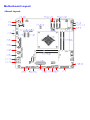
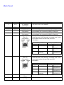
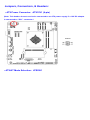
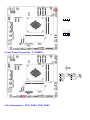
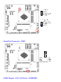
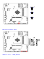
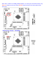
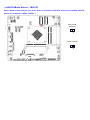
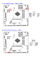
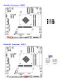
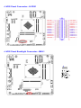
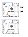
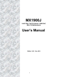
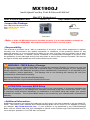
MX1900J
Intel® Quad Core Bay Trail-D Celeron J1900 SoC
Mini ITX Motherboard
User’s Quick Start Card
Version 1.01
http://www.bcmcom.com
• Inspect the Package:
One MX1900J Motherboard
One SATA Power Cable
One I/O Shield
SATA Power Cable
I/O Shield
MX1900J
• Note: In order for MX1900J board to function properly, it is recommended to maintain air
o
flow around MX1900J with ambient temperature not to exceed 33.4 C.
• Responsibility:
This manual is provided “As-Is” with no warranties of any kind, it will neither expressed or implied,
including, but not limited to the implied warranties or conditions of this product’s fitness for any
particular purpose. In no event shall we be liable for any loss of profits, loss of business, loss of data,
interruption of business, or indirect, special, incidental, or consequential damages of any kind, even
the possibility of such damages arising from any defect or error in this manual or product. We reserve
the right to modify and update the user manual without prior notice.
WARNING: CMOS Battery Damage
Replace your system’s CMOS RAM battery only with the identical CR-2032 3V Lithium-Ion coin cell
(or equivalent) battery type to avoid risk of personal injury or physical damage to your equipment.
Always dispose of used batteries according to the manufacturer’s instructions, or as required by the
local ordinance (where applicable). The damage due to not following this warning will void your
motherboard’s manufacturer warranty.
Perchlorate Material- Special Handling May Apply.
See http://www.dtsc.ca.gov/hazardouswaste/perchlorate/
ATTENTION: Incorrect BIOS Setup
If you do not know how to handle BIOS setup or how to set it up properly, it is strongly advisable that
you do not modify any of the settings than otherwise instructed in the User’s Quick Start Card. Even
a seemingly small incorrect adjustment or modification in the BIOS setup can render your system
unstable or unusable. The incorrect BIOS setup is not covered by your motherboard’s manufacturer
warranty.
• Additional Information:
Additional information on setting this board up can be found in the User’s Manual in the provided CDROM. The Online User’s Manual and FAQ/Knowledge Base can be found on our website by visiting
our website: http://www.bcmcom.com. If your question is not answered in our FAQ/Knowledge
Base, visit our forums and post your messages or submit a new FAQ through FAQ Submittal form for
us to add your question in our FAQ with our answer.
WARNING: Electrostatic Sensitive Device (ESD)
Static electricity can easily damage your motherboard and will void your motherboard warranty. Keep
the motherboard and other system components in their anti-static packaging until you are ready to
install them. Touch a grounded surface before you remove any system component from its protective
anti-static packaging. Unpacking and installation should be done on a grounded, anti-static mat. The
operator should be wearing an anti-static wristband, grounded at the same points as the anti-static
mat. During configuration and installation touch a grounded surface frequently to discharge any static
electrical charge that may have built up in your body. Avoid touching the components when handling
the motherboard or a peripheral card. Handle the motherboard and peripheral cards either by the
edges or by the peripheral card case-mounting bracket.
WARNING: Misplaced Jumper Damage
Incorrect setting jumpers and connectors may lead to damage to your motherboard and will void your
motherboard warranty. Please pay special attention not to connect these headers in wrong
directions. DO NOT change ANY jumpers while the motherboard has the power!
Note (Please read this before proceed with OS installation)
1.
Due to “SATA2” and “MINI_CARD1” are sharing the same SATA channel, only either one of them
can be used. Please DO NOT install devices to these two headers at the same time.
2.
If there is only one memory module being installed, install it at memory slot “SODIMM_A1” only.
3.
If “Win7+SP1” is going to be installed, it is recommended to set the BIOS option “Miscellaneous
Configuration” to “Windows 7”.
4.
If “Win8.x” is going to be installed, it is recommended to set the BIOS option “Miscellaneous
Configuration” to “Win8.X”.
5.
If “Linux” is going to be installed, it is recommended to download the latest kernel, the native
driver in the kernel should be able to support the LANs, graphic features.
6.
Please install the provided drivers for the following OS:
a.
Windows 7+SP1
i.
Intel inf
ii.
Intel Graphic
iii.
Intel LAN
iv.
Realtek Audio
v.
Intel TXE base driver
vi.
Intel TXE update driver
vii.
Intel USB3.0 driver (Intel recommended to copy the file to system hard
drive first, then install driver from there).
b.
Win8.x
i.
Intel inf
ii.
Intel Graphic
iii.
Intel LAN
iv.
Realtek Audio
v.
Intel TXE base driver
vi.
Intel MEI driver (Shown as “unknown device” under Device Manager)
Motherboard Layout:
• Board Layout:
• Back Panel:
Item
Name
Function
1
DC1
2
3
4
DP1
VGA1
USB34
5
USB12
6.
LAN2.
DC adapter
Connector
Display Port
VGA Video Port
USB 3.0
Connectors
USB 3.0
Connectors
Gigabit LAN
(RJ-45)
Connectors
Description
The port is for a DC adapter.
The display port Connector
The VGA15-pin Connector.
These two 4-pin Universal Serial Bus (USB) ports
are available for connecting USB 3.0 devices.
These two 4-pin Universal Serial Bus (USB) ports
are available for connecting USB 3.0 devices.
This port allows Gigabit connection to a Local
Area Network (LAN) through a network hub. Refer
to the table below for the LAN port LED
indications.
ACT/Link LED
Status
Description
OFF
No link
7
LAN1
Gigabit LAN
(RJ-45)
Connectors
Orange
Linked
Blinking
Data
activity
Speed LED
Status
Description
OFF
10Mbps
connection
Green
100Mbps
connection
Orange 1Gbps
connection
This port allows Gigabit connection to a Local
Area Network (LAN) through a network hub. Refer
to the table below for the LAN port LED
indications.
ACT/Link LED
Status
Description
OFF
No link
8
AUDIO2
9
AUDIO1
Microphone port
(Pink)
Line-out port
(Lime)
Speed LED
Status
Description
OFF
10Mbps
connection
Orange
Linked
Green
100Mbps
connection
Blinking Data
Orange 1Gbps
activity
connection
This port connects a microphone.
This port connects a headphone or a speaker.
Jumpers, Connectors, & Headers:
• ATX Power Connector: ATX12V1 (4-pin)
(Note: This header doesn’t need to be connected to an ATX power supply if a 12V DC adapter
is connected to “DC1” connector.)
ATX12V1
• ATX/AT Mode Selection: JPSON1
• Front Panel Connector: F_PANEL1
• Fan Connectors: CPU_FAN1, SYS_FAN1
• Serial Port Connector: COM1
1. DCD#
3. TX
5. GND
7. RTS#
9. RI3xPOWERxJMP
• COM1 Ring-In/ +12V/ +5V Select: JCOMPWR1
2. RX
4. DTR#
6. DSR#
8. CTS#
• LPT Port Connector: LPT1
• SATA 3.0 Ports: SATA1, SATA2
(Note: Due to “SATA2” and “MINI_CARD1 (mSATA)” are sharing the same SATA channel, only
either one of them can be used. Please DO NOT install devices to these two headers at the
same time.)
• SATA Power Header: SATAPW1
• mSATA Mode Select: JSATA1
(Note: Remove this jumper only when there is trouble for BIOS to detect the installed mSATA
device on connector “MINI_CARD1”.)
Auto mode
(Default)
Force mSATA
• Front USB2.0 Headers: USB56, USB78
Front Panel Audio Connector: AAFP1
2
1
10. LINE2-JD
8. NC
6. MIC2-JD
4. +3.3
2. GND
9. LINE2L
7. SENSEB
5. LINE2R
3. MIC2R
1. MIC2L
• Amplifier Connector: JAMP1
1
• Digital I/O Connector: JDIO1
1. SIO_GPIO0
3. SIO_GPIO1
5. SIO_GPIO2
7. SIO_GPIO3
9. SMB_CLK_
RESUME
11. GND
2. SIO_GPIO4
4. SIO_GPIO5
6. SIO_GPIO6
8. SIO_GPIO7
10. SMB_DATA_
RESUME
12. +5Vsb
• LVDS Panel Connector: JLVDS1
• LVDS Panel Backlight Connector: JBKL1
• Clear CMOS Jumper: CLCMOS1
• Mini PCI Express Slot: MINI_CARD1, MINI_CARD2