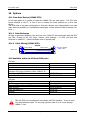
1
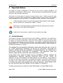
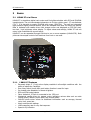
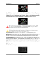
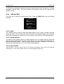
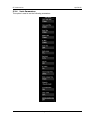
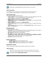
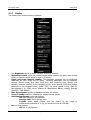
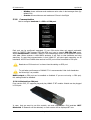
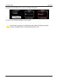
S7 Version 4.90
April 2015
S7
Digital speed to fly variometer and final glide calculator
Version 4.90
LXNAV d.o.o. • Kidričeva 24a, 3000 Celje, Slovenia • tel +386 592 33 400 fax +386 599 33 522
[email protected] • www.lxnav.com
Page 1 of 49
S7 Version 4.90
1
Important Notices
1.1
2
3
April 2015
5
Limited Warranty
5
Packing Lists
Basics
6
7
3.1 LXNAV S7 at a Glance
3.1.1 LXNAV S7 Features
3.1.2 Interfaces
3.1.3 Options
3.1.3.1
External Options
3.1.4 Technical Data
4
7
7
8
8
8
8
System Description
9
4.1.1 Push Button
4.1.1.1
Power Button
4.2 Rotary Switch
4.3 Switching on the Unit
4.4 User Input
4.4.1 Text Edit Control
4.4.2 “Spin” Control
4.4.3 Selection Control
4.4.4 Checkbox and Checkbox List
4.4.5 Slider selector
4.5 Switching off
5
9
9
9
10
10
11
11
11
11
12
12
Operating Modes
13
5.1 Main screen and needle
13
5.1.1 Flarm Warning
14
5.1.2 Direct link between PDA and GPS
14
5.2 Quick access menu
15
5.3 Settings Mode
16
5.3.1 Navigate
16
Target information can be received from PDA or GPS. This setting is very important if
we want to see “Arrival Altitude”. “Arrival altitude” will be displayed only if S7 will have
all necessary data to calculate “arrival Altitude”. The most problematic data is elevation
of target, which can be set manually in Target elevation menu or automatically received
from GPS or PDA port. If any of those setting will not be correct S7 will calculate only
Required Altitude.
17
5.3.2 Logbook
17
5.3.3 QNH and RES
18
5.3.3.1
QNH
18
5.3.3.2
Safety Altitude
18
5.3.3.3
Set elevation
18
5.3.4 Vario Parameters
19
5.3.4.1
Some definitions
20
5.3.4.2
Vario needle filter
20
5.3.4.3
Vario sound filter
20
5.3.4.4
Netto filter
20
5.3.4.5
Relative filter
20
5.3.4.6
SC filter
20
5.3.4.7
Smart Filter
21
5.3.4.8
Needle range
21
5.3.4.9
Dead Band (SC tab)
21
5.3.4.10
Auto SC
21
Page 2 of 49
S7 Version 4.90
6
April 2015
5.3.4.11
SC switch
5.3.4.12
Vario Average Time
5.3.4.13
Netto Average Time
5.3.4.14
Auto reset integrator
5.3.4.15
TE compensation
5.3.4.16
Temperature Offset
5.3.4.17
Inertial assisted vario
5.3.5 Sounds
5.3.5.1
Sounds settings
5.3.5.2
Equalization
5.3.6 Units
5.3.7 Display
5.3.8 Communication
5.3.8.1
Bluetooth on PDA port
5.3.9 Polar and Glider
5.3.10
Flarm
5.3.11
Password
5.3.12
Reset of accelerometer (g-meter)
5.3.13
About
21
22
22
22
22
23
23
23
24
26
27
28
29
29
31
32
32
33
33
Variometer and Altimeter
34
Altimeter
6.1 Speed Command
7
34
34
Flying with the LXNAV S7
35
7.1 On the Ground
7.1.1 Power on Procedure
7.1.2 Set Elevation and QNH
7.1.3 Pre-flight Check
7.2 Airborne
7.2.1 Final glide calculation
8
35
35
35
36
36
36
Installation
37
8.1 Installing the LXNAV S7
8.2 Connecting LXNAV S7
8.3 Cutout of S7
8.4 Installation of options
8.4.1 Ports and Wiring
8.4.1.1
LXNAV S7 ports
8.4.1.2
LXNAV S7 wiring
8.4.2 Configurations
8.4.2.1
NANO – S7 – OUDIE
8.4.2.2
NANO3 – S7 – MINIMAP
8.4.2.3
COLIBRI2 – S7 – OUDIE
8.4.2.4
COLIBRI,VOLKSLOGGER– S7 – OUDIE
8.4.2.5
Flarm/RedBox– S7 – OUDIE
8.4.2.6
FlarmMouse - FlarmView -S7 - OUDIE
8.4.2.7
FlarmMouse – S7 – OUDIE
8.4.3 S7D option (S7 repeater)
9
Firmware Update
9.1
9.2
10
45
Updating LXNAV S7 firmware using OUDIE
Updating LXNAV S7 firmware using PC
Options
10.1
38
38
38
39
39
39
41
41
41
42
42
42
42
43
43
44
45
46
48
Rear Seat Device (LXNAV S7D)
Page 3 of 49
48
S7 Version 4.90
April 2015
10.1.1
Data Exchange
10.1.2
Cable Wiring (LXNAV S7D)
10.2
Available cables for GPS and PDA ports
11
Revision History
48
48
48
49
Page 4 of 49
S7 Version 4.90
1
April 2015
Important Notices
The LXNAV S7 system is designed for VFR use only as an aid to prudent navigation. All
information is presented for reference only. Terrain, airports and airspace data are provided
only as an aid to situation awareness.
Information in this document is subject to change without notice. LXNAV reserves the right
to change or improve their products and to make changes in the content of this material
without obligation to notify any person or organisation of such changes or improvements.
A Yellow triangle is shown for parts of the manual which should be read carefully
and are important for operating the LXNAV S7 system.
Notes with a red triangle describe procedures that are critical and may result in
loss of data or any other critical situation.
A bulb icon is shown when a useful hint is provided to the reader.
1.1 Limited Warranty
This LXNAV S7 product is warranted to be free from defects in materials or workmanship for
two years from the date of purchase. Within this period, LXNAV will, at its sole option, repair
or replace any components that fail in normal use. Such repairs or replacement will be made
at no charge to the customer for parts and labour, the customer shall be responsible for any
transportation cost. This warranty does not cover failures due to abuse, misuse, accident, or
unauthorised alterations or repairs.
THE WARRANTIES AND REMEDIES CONTAINED HEREIN ARE EXCLUSIVE AND IN LIEU OF
ALL OTHER WARRANTIES EXPRESSED OR IMPLIED OR STATUTORY, INCLUDING ANY
LIABILITY ARISING UNDER ANY WARRANTY OF MERCHANTABILITY OR FITNESS FOR A
PARTICULAR PURPOSE, STATUTORY OR OTHERWISE. THIS WARRANTY GIVES YOU
SPECIFIC LEGAL RIGHTS, WHICH MAY VARY FROM STATE TO STATE.
IN NO EVENT SHALL LXNAV BE LIABLE FOR ANY INCIDENTAL, SPECIAL, INDIRECT OR
CONSEQUENTIAL DAMAGES, WHETHER RESULTING FROM THE USE, MISUSE, OR
INABILITY TO USE THIS PRODUCT OR FROM DEFECTS IN THE PRODUCT. Some states do
not allow the exclusion of incidental or consequential damages, so the above limitations may
not apply to you. LXNAV retains the exclusive right to repair or replace the unit or software,
or to offer a full refund of the purchase price, at its sole discretion. SUCH REMEDY SHALL
BE YOUR SOLE AND EXCLUSIVE REMEDY FOR ANY BREACH OF WARRANTY.
To obtain warranty service, contact your local LXNAV dealer or contact LXNAV directly.
March 2012
© 2012 LXNAV. All rights reserved.
Page 5 of 49
S7 Version 4.90
2
•
•
•
•
April 2015
Packing Lists
LXNAV S7 (in Metric or Imperial units as specified)
Main power cable for S7 + CAN terminator
Speaker
GPS cable - S7-GPS-IGC
Page 6 of 49
S7 Version 4.90
3
April 2015
Basics
3.1 LXNAV S7 at a Glance
LXNAV S7 is standalone digital vario meter and final glide calculator with GPS and PDA/PNA
inputs/outputs. The unit has standard dimensions to fit into a glider panel - 57 mm diameter
(2¼"). It is also able to supply PDA/PNA with power (5VDC/1A). The unit has integrated
high precision digital pressure sensors, which are sampled more than 100 times per second.
Data is indicated with needle driven with stepper motor and displayed on 320*240 pixel,
two-inch, high brightness colour display. To adjust values and settings, LXNAV S7 has one
rotary knob combined with a push button.
LXNAV S7 can be expanded through CAN bus to one or more repeaters (LXNAV S7D). Both
pilots can have equal control of all functions from front or rear seat.
3.1.1
•
•
•
•
•
•
•
•
•
•
LXNAV S7 Features
Extremely bright 2" (5 cm) colour display readable in all sunlight conditions with the
ability to adjust the backlight .
One rotary switch (knob) with push button function is used for input.
Pre-loaded polar database for almost all gliders.
GPS and PDA inputs/outputs
Flarm Indication, if Flarm is connected to the GPS port
Mechanical needle driven by stepper motor indicating various data such as netto
vertical speed, relative (super netto) and vertical speed.
240x320 pixels colour screen for additional information such as average, thermal
vario, time, speed etc…
Many custom audio settings
100Hz sampling rate for very fast response.
Speed to fly indication.
Page 7 of 49
S7 Version 4.90
•
•
•
3.1.2
•
•
•
•
April 2015
TE compensation can be selected to be either pneumatic TE probe or electronic TE.
Multilanguage user interface
Audio equalizer, for better vario sound performance
Interfaces
GPS port input/output on RS232 level (Standard IGC RJ11 connector)
PDA port input/output on RS232 or LV-TTL (3.3V) level for PNA devices (RJ45 connector)
Audio port (Standard 3mm phono jack)
1Mbit CAN bus for extension to S7D repeater
3.1.3
Options
3.1.3.1 External Options
By using a CAN bus system a second seat device can be connected. The unit installed in the
rear seat of the glider is independently powered and receives all necessary data from the
main unit. The communication between both units is exclusively via the CAN bus system.
3.1.4
•
•
•
•
•
Technical Data
Power input 10-16 V DC
Consumption of LXNAV S7 at 12 V:
o 120 mA - minimum brightness without audio.
o 180 mA - maximum brightness without audio.
Consumption of LXNAV S7D at 12 V:
o 90 mA - maximum brightness without audio.
57 mm (2¼") standard aircraft cut-out for the LXNAV S7 vario unit; length 95 mm (not
including connector).
Weight 330g (160g for S7D)
Page 8 of 49
S7 Version 4.90
4
April 2015
System Description
4.1.1
Push Button
The Rotary switch also has a push button function. LXNAV S7 can detect short or long press
of push button, in most cases short press confirms action, long press cancels action or exits
from the menu Short press means just a click, long press means pushing button for more
than one second.
4.1.1.1 Power Button
The system is powered up using push button. A long press system will turn the S7 off.
4.2 Rotary Switch
The one rotary switch/knob with integrated pushbutton function can control all functions on
LXNAV S7. The rotary switch moves up or down through the menus. Variables can also be
changed using the switch. Pushing the button at the same time as rotating will step the
values in larger increments.
Example 1:
Set elevation menu; normally, values are with step 1m. If you push button in and rotate at
same time, the step will be 10m.
Example 2:
Entering password; Up/Down the numbers are changed. If you press and rotate, the cursor
will move left or right. Short press will move cursor one step right.
Rotary switch with
push button
Page 9 of 49
S7 Version 4.90
April 2015
4.3 Switching on the Unit
A short press of the button with turn on the S7. The first LXNAV welcome screen will
appear with some system information (Device name, Version, Serial number...)
S7D cannot be powered up if S7 is not already powered up.
When the boot procedure is completed, setup elevation dialogue is shown.
By default setting Set Elevation page is disabled. It can be enabled in Setup
QNH&RES menu.
Push button also has power ON and OFF functions.
4.4 User Input
The LXNAV S7 user interface consists of many multi language dialogues which have different
input controls. They are designed to make input of names, parameters, etc., as easy as
possible. Input controls can be summarised as:
• Text editor
• Spin controls (Selection control)
• Checkboxes
• Slider control
To move the function from one control to another, rotate the rotary knob up or down as
follows:
• Clockwise rotation will select the next control.
• Counter clockwise rotation will select the previous control. PUSH button enters the
selected feature.
Page 10 of 49
S7 Version 4.90
4.4.1
April 2015
Text Edit Control
The Text Editor is used to input an alphanumeric string; the picture below shows typical
options when editing text. Use the knob to change the value at the current cursor position.
Push button will move cursor right. Holding push button and rotationg knob, will move
cursor left or right. At last character position, push button will confirm edited value, long
press will cancel editing and exit that control.
4.4.2
“Spin” Control
“Spin” controls are designed for numeric parameters. Rotate the knob to increase/decrease
the selected value. Combination of push button and knob rotation will change the value with
a larger step. .
4.4.3
Selection Control
Selection boxes, also known as combo boxes are used to select a value from a list of
predefined values. Use the page selector to scroll through the list.
4.4.4
Checkbox and Checkbox List
A checkbox enables or disables a particular parameter. Press push button to toggle the
value. If an option is enabled a check mark will be shown, otherwise an empty rectangle will
be displayed.
Page 11 of 49
S7 Version 4.90
4.4.5
April 2015
Slider selector
Some values like volume and brightness are displayed as a slider
With push button you can activate slider control, then with rotation of the knob you can
select the preferred value and confirm it with the push button.
4.5 Switching off
By pressing the push button for app. 5 seconds, LXNAV S7 will turn off. Same procedure is
for S7D, if S7D is on and we are attempting to switch off S7, S7D will also switch off.
All settings are saved in the power off procedure. We strongly recommend
switching off the unit using push button and not use a separate master switch..
If the system is powered off by a master switch changed data will not be saved.
Flight parameters at takeoff like target altitude and position will remain in stored
memory so your final glide calculations are not affected.
Page 12 of 49
S7 Version 4.90
5
April 2015
Operating Modes
LXNAV S7 has three operating modes. A pilot has access to all of them using rotary knob and
push button. The diagram below shows the mode structure of the LXNAV S7.
•
•
•
Main screen, all navigation and flight parameters defined by pilot
Quick access, MacCready, Ballast, Bugs, Distance (in manual navigation without GPS)
and Wind component (in manual navigation).
Settings, setup of the whole system
5.1 Main screen and needle
The man screen has a mechanical needle and a 320x240 color display with user selected
data.
Description of LXNAV S7 is shown on next picture.
Range
Mechanical needle
Upper number
Thermal average
Flarm status
MacCready symbol
Climb/cruise symbol
Accelerometer bar
Speed to fly bar
Needle type
Battery
Average/G-force
/
GPS status
To Home navigation
Bluetooth status
Lower number
Rotary knob & push
button
Mechanical needle displays vario, netto, relative or speed to fly value. It can be setup
scale can be chosen (when ordered) in the range of -5 to 5 or from -10 to 10. Within the
software the range can be set to 2.5, 5, 10m/s or 5, 10, 20kts or 500, 1000, 2000fpm.
Page 13 of 49
S7 Version 4.90
April 2015
Upper number can be configured as average vario, time, flight time, task remaining time,
netto value, outside temperature or thermal average, steering course. It can be setup
separately for climb mode or cruising mode.
Lower number shows current altitude, distance to goal, arrival altitude, true airspeed, Last
60 minutes speed, altitude in feet or flight levels.
Speed to fly bar symbol is indicating which speed you have to fly according to current
MacCready setting, sink rate and speed. One arrow means 10units of speed faster or slower.
Up red arrows mean fly slower and down blue arrows mean fly faster.
Red diamond symbol can show average vertical speed or g-force.
Blue arrow symbol shows current MacCready value.
Green T symbol represents last thermal average value.
White bar, which is not shown on the picture above, displays arc between minimum and
maximum vertical speed value in last 20 seconds.
In LXNAV S7 there is an integrated 3 axis +-6g accelerometer. All accelerations can be
recorded and indicated with accelerometer red bar. Red bar, which is not shown on picture
above, displays maximum negative and positive acceleration in g.
BlueTooth symbol indicates detected BlutoothModule for S7 on PDA port.
Flarm symbol indicates presence of flarm device (pink) and also detection of flarm traffic
(red).
5.1.1
Flarm Warning
If Flarm warnings are enabled the following is a typical screen display:
The screen indicates relative position of threat. In the first image two gliders are
approaching inbound below, the second screen two gliders are approaching inbound, one on
left side and another the right . On third image we have active “undirected warning”
together with other flarm warnings with known direction.
5.1.2
Direct link between PDA and GPS
LXNAV S7 is able to make direct link connection between PDA and GPS. Normally GPS and
PDA communicate with LXNAV S7. In the direct link mode the user can transfer data from
PDA to GPS (Flight recorder) or the opposite way (read the flight). The direct link is
normally initiated by software such as SeeYou Mobile or ConnectMe.
Page 14 of 49
S7 Version 4.90
April 2015
The picture above indicates a direct link. This happens automatically when PDA send a
request for direct communication with flight recorder.
See tutorial on: http://youtu.be/nMZI7cJ_qjQ
5.2 Quick access menu
A short press of the push button activates the quick access menus. If “use
navigation” is checked, only three Mc, Bugs and Bal are available. If “use
navigation” is disabled two additional settings are available (Wind component
distance).
In the last row of the box is calculated final glide (E) and required speed for that
glide, values depends on MacCready, Bugs and Ballast setting.
Page 15 of 49
GPS
GPS
and
final
S7 Version 4.90
April 2015
5.3 Settings Mode
In the setup menu users can configure the LXNAV S7. Turn the knob to select the
appropriate setup item. Press the PUSH button to enter a menu. A dialogue or sub-menu
will open.
5.3.1
Navigate
In this menu navigation settings can be configured.
If Navigate to home is enabled, LXNAV S7 will navigate back to the takeoff point. This
position has been stored in memory just before takeoff but only if GPS OK status is showing.
Navigate to home will not work if “use GPS data” is not checked.
Page 16 of 49
S7 Version 4.90
April 2015
Use GPS data, enables the V 7 to receive GPS data on GPS port. If Use GPS data is
disabled manual navigation will be active, in that case GPS icon on main screen will not be
displayed. It means that pilot must manually enter distance and wind component (See
Chapter 5.2). If GPS is transmitting RMB sentences, LXNAV S7 will automatically calculate
final glide to that point. On picture below LXNAV S7 navigates to waypoint “Line 11”.
Be sure that you set correct target elevation. If target elevation is not set, LXNAV
S7, will not show Arrival altitude, but Required altitude. Required altitude is
the altitude that will be lost for the required distance.
GPS data will be received only if baudrate on GPS side is set at the same value as
set on LXNAV S7 in Comm. Menu. (See Chapter 5.3.8 )
Target elevation set to elevation of your departure. It can be adjusted any time.
Manual wind can be checked, when pilot wants to insert fixed value of wind component. In
that case S7 will not use it’s calculated wind for final glide calculations, but manual enterd.
Target information can be received from PDA or GPS. This setting is very important if we
want to see “Arrival Altitude”. “Arrival altitude” will be displayed only if S7 will have all
necessary data to calculate “Arrival Altitude”. The most problematic data is elevation of
target, which can be set manually in Target elevation menu or automatically received from
GPS or PDA port. If any of those setting will not be correct S7 will calculate only Required
Altitude.
5.3.2
Logbook
Each flight is stored in logbook.
Page 17 of 49
S7 Version 4.90
April 2015
If GPS data is present the logbook will show present date and time of departure. Manual
navigation (without GPS) will show duration and departure time will be marked with
question marks.
5.3.3
QNH and RES
Turn the knob to select the required entry field. Press the PUSH button and start editing
the value.
5.3.3.1 QNH
This feature may be used to offset the altitude datum as the result of pressure changes
during the flight. Since changing the QNH influences the indicated altitude, care should be
taken when changing the value as an incorrect setting could upset the final glide calculation.
5.3.3.2 Safety Altitude
This setting is the altitude reserve or safety altitude and is the height that the instrument
adds to the final glide altitude required so the glider arrives over the final glide destination at
the selected safety altitude. Once the safety altitude has been specified, the pilot has to
keep the final glide indicator on 0 to arrive at the safety altitude.
5.3.3.3 Set elevation
If Set Elevation – show on start-up, item is not checked, Set elevation menu, will not be displayed
during start up. In this case elevation will be set to standard QNE (Flight level).
Page 18 of 49
S7 Version 4.90
5.3.4
April 2015
Vario Parameters
This option is used to set the following parameters:
Page 19 of 49
S7 Version 4.90
April 2015
5.3.4.1 Some definitions
Vario
Vario is defined as the measurement of the gliders vertical speed. This signal is generally
total energy compensated, what means that parts of the signal, coming from the change in
the gliders horizontal speed (Conversion from kinetic energy into potential energy and vice
versa), are taken out. This can be done by a TE tube or arithmetical (electronically
compensation)
Netto
From the variosignal the vertical speed of the air mass is calculated, by taking into account
the gliders parameter (polar and weight) and current horizontal speed (IAS).
Relative
If you subtract the gliders sinkrate while circling from Netto, you will get the vario value
which you would see, when starting to circle ideally at the current position. This value is
called Relative. The sinkrate is taken from the polar for straight flight, therefore the Relative
value is a little bit optimistic
Speed to fly
There are two terms in use:
Speed to Fly (STF) is the speed one should fly at given parameters like MacCready setting,
polar, weight/wing load and current vertical speed, to be optimal in time between the
thermals according to the MacCready theorie.
Speed Command (SC) is the interpretation of the STF in a needle and/or audio singal,
which shows the difference to the ideal STF in a way, that the pilot can interpret it as a
steering command (push/pull).
5.3.4.2 Vario needle filter
Sets a time constant of the vario needle. The value can be adjusted between 0.1 and 5 s
with step 1.0 s or 0.1 s. Default value is 1.5 s.
5.3.4.3 Vario sound filter
Sets a time constant of vario sound. The value can be adjusted between 0.1 and 5 s with
step 1.0 s or 0.1 s. Default value is 1.5 s.
5.3.4.4 Netto filter
Sets a time constant of the Vario Netto needle. The value can be adjusted between 0.1
and 5 s with step 1.0 s or 0.1 s. Default value is 1.5 s.
5.3.4.5 Relative filter
Sets a time constant of the Vario Relative needle. The value can be adjusted between 0.1
and 5 s with step 1.0 s or 0.1 s. Default value is 1.5 s.
5.3.4.6 SC filter
Sets a time constant of the SpeedToFly needle. The value can be adjusted between 0.1
and 5 s with step 1.0 s or 0.1 s. Default value is 1.5 s.
Page 20 of 49
S7 Version 4.90
April 2015
5.3.4.7 Smart Filter
The Smart Filter allows additional filtering of the vertical speed. It defines the difference
between increasing vertical speed versus decreasing vertical speed. (E.g.: If the vario filter
is set to 1s and the Smart Filter set to 4s, the filtering for increasing vario would be 1s and
for decreasing vario would be 2s. This will produce an effect similar to a Sage Variometer.)
RAW
VARIO
VARIO
INDICATOR
FILTERED
VARIO
FILTER
0.5 to 5
Smart Vario
FILTER
1 to 8 or OFF
5.3.4.8 Needle range
Sets full scale range of the vario (2.5 m/s, 5 m/s or 10 m/s). Default value is 5 m/s (10 kts).
5.3.4.9 Dead Band (SC tab)
Defines the width of the audio dead band in speed to fly mode. Default value is ±1 m/s.
5.3.4.10
Auto SC
Defines the conditions when the instrument will switch automatically between vario and
speed to fly mode.
• OFF: Switching is exclusively by an external switch connected to the S7.
• GPS: When the GPS detects that the glider is circling an automatic change over to vario
will happen after approximately 10 seconds. Detection of straight flight will cause a
changeover to speed command.
• TAS: When the TAS exceeds a pre-set value. The TAS at which switching occurs can be
selected in 5 km/h steps from 100 up to 160 km/h (or the equivalent in knots or mph).
• G-meter – for switching between cruise and climb mode will be used inertial system.
When glider will start circling, S7 will automatically switch from cruise to climb mode.
The external switch wired to the LXNAV S7 has absolute priority and will override
all other switching methods.
5.3.4.11
SC switch
The LXNAV S7 has an input for an external speed command switch. Using the external
switch it is possible to switch between SC and Vario manually. Setting the SC switch to ON
means that closing the switch will cause the instrument to enter SC mode and setting SC
switch to OFF means that closing the switch will select Vario mode. There is a third option
by setting SC INPUT to TASTER and connecting a push button to the input; each key press
will toggle between SC and Vario (mandatory setting for LX Remote).
There is another input called VARIO PRIORITY. When this input is activated by
grounding the appropriate wire the unit will change over to Vario immediately.
This input wire is set open (not grounded) as a factory default on delivery.
Page 21 of 49
S7 Version 4.90
5.3.4.12
April 2015
Vario Average Time
Defines the integration period for the average vario in seconds. The default is 20 seconds.
5.3.4.13
Netto Average Time
Defines the integration period for the average netto vario in seconds. The default is 10
seconds.
5.3.4.14
Auto reset integrator
Resets the integrator to zero when the S7 vario unit switches from SC to VARIO mode. If
this item is not checked the integrator will not be reset to zero.
5.3.4.15
TE compensation
The LXNAV S7 offers two methods of vario Electronic Total Energy Compensation:
• TE Pitot tube
• Electronic TE compensation
It is important to note that the method of TE compensation is set up when the
instrument is installed by virtue of the pneumatic connections made to the TE and
static ports. Changing the compensation type in the setup screen below WILL
NOT change the method of compensation - the pneumatic plumbing has to be
changed first.
If the TE pitot tube has been connected TE compensation should be set to 0%.
There is no further adjustment of TE compensation possible. Quality of the TE
tube is the one and only factor.
If the electronic TE option has been installed TE compensation should be set to
100%.
The electronic TE compensation can be fine-tuned during flight using the following
procedure: it is essential that this is only done in smooth air; it is not possible to tune the
TE accurately in turbulent air.
Set TE compensation to 100%. Accelerate up to approximately 160 km/h (75 kts) and keep
the speed stable for a few seconds. Gently reduce the speed to 80 km/h (45 kts). Observe
the vario indicator during the manoeuvre. At 160 km/h the vario will indicate about –2 m/s
(-4 kts). During the speed reduction the vario should move towards zero and should never
exceed zero (slightly positive indications are acceptable). If the vario shows a climb the
compensation is too low; increase the TE%; and vice versa. Try another “zoom” to assess
the change and make further adjustments if necessary.
Electronic TE compensation is only effective when the pitot tube and static sources are colocated and the pneumatic lines to the instrument are approximately the same length. The
best sensor to use is the combined pitot/static Prandtl tube. If problems are experienced
with the electronic TE compensation the most likely cause is the glider's static source. The
static source can be checked by plumbing the pneumatic tubes for electronic compensation
and then setting the TE: to 0%. In still air accelerate to approximately 160 km/h and slowly
reduce the speed. Observe the vario indicator. If the static source is good the vario should
immediately start to move to show a climb. If the needle firstly shows increased sink and
then moves to a climb, the static source of the glider is unsuitable and there is no way to
Page 22 of 49
S7 Version 4.90
April 2015
provide successful TE compensation electronically. The use of a dedicated and accurate finmounted pitot/static source such as a Prandtl tube might help.
5.3.4.16
Temperature Offset
The LXNAV S7 is supplied with an external outside air temperature (OAT) sensor. With the
offset setting it will correct static errors of temperature measurement.
5.3.4.17
Inertial assisted vario
With LXNAV S7 possible to adjust influence of g-force on vario. This influence is very small
and can be set between 0 and 4.
5.3.5
Sounds
Sound menu is divided on two parts sound setting and Equalizer
Page 23 of 49
S7 Version 4.90
April 2015
5.3.5.1 Sounds settings
In the Sounds settings menu audio settings for the LXNAV S7 and alarms settings can be
modified.
Vario Volume
The sounds slider changes the audio volume.
Page 24 of 49
S7 Version 4.90
April 2015
Volume can be also adjusted directly with rotary knob in main menu.
Vario waveform
In this setting user can change the form of audio signal. There are three oprions:
Pure sine shape of signal, triangular or harmonic (sum of more Sine waves).
Vario Audio mode
Vario audio mode has the following options:
• Linear positive: sound is interrupted with silence every few milliseconds when the
needle is positive; on negative side sound is linear (not interrupted).
• Linear negative: inverse function to Linear positive.
• Linear: sound is linear and non-interrupted in full scale range.
• Digital positive: similar to Linear positive, except frequency is not changing linearly
but with larger steps.
• Digital negative: inverse function to Digital positive.
• Linear positive only: sound is present only at positive values, for negative values there
is silence.
• Digital positive only: similar function to Linear positive only, except the sound is
similar to the digital tone.
SC Audio mode
SC audio mode has four modes:
• SC positive: sound is interrupted with silence every few milliseconds when the needle is
positive; on negative side sound is linear (not interrupted).
• SC negative: inverse function to SC positive.
• SC: sound is linear and non-interrupted in full scale range.
• SC Mixed: for positive relative values the sound represents relative; for negative
relative values the sound represents SC (for that setting it is recommended to set SC
needle to relative). Dead band is active only for negative values.
• SC Netto: Sound follows netto value.
Audio frequencies
•
•
•
Freq at 0% defines the tone frequency at 0 m/s.
Freq at +100% defines the tone frequency at full + deflection.
Freq at -100% defines the tone frequency at full – deflection.
Equalization preset
We have three options: default LXNAV speaker, flat setting or user defined.
Flarm Volume
With Flarm volume slider the volume of flarm warning beeps can be changed.
Volume can be also adjusted directly with rotary knob in main menu but only at
the moment that the Flarm alarm is active.
Page 25 of 49
S7 Version 4.90
April 2015
Flarm warnings
In this
•
•
•
•
menu low level/important/urgent Flarm alarm types can be set. We have four options:
Disabled
Flarm Beep
Short voice message
Long voice message
Beeps requested from PDA
PDA is able to send beep command to S7, if that feature is enabled, S7 will beep on PDA
request.
Thermal Assistant
Is a sound, different from other sounds from S7, which helps to the pilot in a thermal. Pilot
can set, how many seconds before thermal maximum, thermal „Ping“ will be triggered.
Speech Volume
With Speech volume slider the volume of voice warnings can be changed.
Volume can be also adjusted directly with rotary knob in main menu but only at
the moment that the voice is active.
5.3.5.2 Equalization
With rotary knob can be adjusted volume for each frequency. Setting is stored
under user preset.
Set equalizer to flat, then find the loudest frequency and decrease it to minimum.
Then adjust other frequencies to be heard at the same volume.
Page 26 of 49
S7 Version 4.90
5.3.6
April 2015
Units
Use this menu to specify units, UTC time offset and type of ballast input.ž
•
•
•
Load, which is entered in kg/m2 or lb/ft2.
Weight of water ballast, which is entered in kg or lb . If this option is used the weights
of the glider and pilot must be entered. Refer to Chapters 5.3.9 for more details of how
to enter glider and pilot weights.
Ballast can be displayed as Overload factor or Wing Load or just weight of ballast.
Page 27 of 49
S7 Version 4.90
5.3.7
April 2015
Display
The display menu controls screen brightness.
•
•
•
•
•
•
•
Use Brightness control to adjust intensity of the LCD backlight.
Mechanical needle, which can indicate vertical speed, speed to fly value, netto vertical
speed, or Relative vertical speed in vario or SC mode.
Upper and Lower Numeric Display: The parameter displayed can be configured
separately for Vario mode and SC mode. Following parameters can be displayed:
average vertical speed, local time, flight time, task remaining time, Altitude (NN
altitude), Distance (distance to the navigation point), Arrival altitude (final glide altitude
difference to the navigation point), Speed (TAS), Leg speed (speed on leg), QNH (ft)
(NN altitude in ft), Flight levels, Outside air temperature, Battery voltage, Average
NettoQFE, Total Altitude.
Blue Arrow Symbol enables or disables to display MC symbol
Green T Symbol enables or disables the display thermal symbol
Red Diamond Symbol have three options:
o OFF Red diamond is not displayed
o Average vario Shows average vario
o G-meter shows actual G-force (one line means 1g, the range of
accelerometer indication is +/-5g, you should not look at vario dial)
Bar has three options:
o OFF bar is not displayed
Page 28 of 49
S7 Version 4.90
o
o
5.3.8
April 2015
MinMax shows minimum and maximum vario value in last avereger time (by
default 20s)
G-meter shows minimum and maximum G-force in last flight
Communication
Use to configure baudrate for GPS and PDA port.
Each port can be configured separately. If your PDA device does not support automatic
switch to DIRECT LINK between GPS and PDA port, here is manual GPS-PDA link menu.
When autobaudrate is enabled, LXNAV S7 will automatically search on all speeds to receive
valid data. When receives a valid NMEA sentence it will lock on that baudrate and stop
searching. In case that communication is lost LXNAV S7 will start again searching on all
baudrates. All GPS and FLARM data received on GPS port will be forwarded to PDA port.
Baudrate on PDA must not be lower than the setting on GPS port
To get better performance of LXNAV S7 it is recommended that both baudrates
be set as high as possible.
NMEA output on PDA port can be enabled or disabled. If you are not using a PDA port,
this setting should be disabled.
5.3.8.1 Bluetooth on PDA port
From version 2.02, S7 supports plug and play LXNAV S7 BT module. Module can be plugged
in PDA port.
In case, that we want to use this module, we must select under PDA baudrate LXS7
Bluetooth. If Bluetooth will be detected, on main screen will be displayed BT icon.
Page 29 of 49
S7 Version 4.90
April 2015
In case of synchonization erreor, an error message will appear.
At power up of S7 same messages will be present.
On PDA side is necessary to pair Bluetooth with LXNAV S7 Bluetooth module.
Pairing is completed, when is entered pairing code „1234“.
Page 30 of 49
S7 Version 4.90
5.3.9
April 2015
Polar and Glider
Use this dialogue to enter glider polar and other glider properties.
standard class glider is enabled automatically .
As a default polar a
Polars for most modern gliders are already prepared. Use Glider type control, to list between
preloaded glider polars.
All glider data will be copied from the chosen polar. The check the best glide ratio and
minimum sink rate, to see if the polar data matches the glider performance, you may look in
MacCready setting menu. You can modify the polar by changing coefficients a, b and c. A
polar is defined as a quadratic equation with the parameters a, b, and c. Use the SeeYou
program (Tools->Polar) to calculate coefficients a, b and c for a given glider’s polar. The
program requires three sink points entered at selected speeds (e.g.: 100 km/h, 130 km/h,
and 150 km/h). The program will calculate the values of a, b and c, which should be noted
and entered into the LXNAV S7.
Stall speed is used to generate stall warnings which are available only with integrated Voice
module (Not integrated in LXNAV S7).
Page 31 of 49
S7 Version 4.90
April 2015
Weights must be entered and user should enter ballast in kilograms. There are three
weights to enter. Min. Weight (Minimum glider weight) corresponds to the min.load value
and represents the value at which the polar was measured or recalculated. Max. weight
(Maximum glider weight) is the maximum take-off weight allowed for a glider. It is not used
in the calculation, it is just a reminder to the pilot of the maximum take-off weight. Empty
weight (Empty glider weight) is weight of the glider without pilot and ballast. The overload
factor is calculated as:
overload =
Empty.glider.weight + Pilot .weight + Water .ballast
Minimum.glider.weight
Empty glider weight is a weight of empty glider. This number can be found in a glider
book.
Pilot weight is weight of the pilot with parachute and baggage.
Water ballast is a weight of ballast.
Minimum glider weight is a weight of empty glider + minimum pilot weight. This value is
useful for when we want to display ballast in weight (kg or lbs).
Maximum glider weight is MTOW (max. takeoff weight) – this value is used only to limit
pilot to enter higher ballast, as is allowed with MTOW.
5.3.10 Flarm
By enabling the item, show flarm warning, Flarm warnings will be shown on the main
screen.
Each warning can be dismissed with push button. Dismiss time is time period during which
the instrument will not give you any warning after pressing dismiss. In the event that
dismiss while circling is enabled, the dismiss period will be extended until end of circling
flight is detected.
5.3.11 Password
There are several passwords which run specific procedures as listed below:
• 00666 Resets all settings to factory default
• 99999 will clean logbook
• 01048 can adjust needle on zero. (necessary only after update to version 2.0)
• 01049 can align airspeed on zero.
Page 32 of 49
S7 Version 4.90
April 2015
Do not adjust needle, or autozero when airborne.
5.3.12 Reset of accelerometer (g-meter)
Accelerometer can any time be reset manually. After take off it is reset automatically.
5.3.13 About
In about page is information about firmware versions, hardware versions and serial
numbers.
Page 33 of 49
S7 Version 4.90
6
April 2015
Variometer and Altimeter
All signals from the pneumatic sensors (altitude, speed) are derived from high quality
pressure sensors which mean that no flask is necessary. The vario signal is derived from the
altitude signal. All signals are temperature and altitude compensated. Mechanical needle
and colour display show the vario information as well as many other parameters.
The display is user configurable. The variometer can be configured to show:
• Range 5, 10 and 2.5 m/s or 10, 20 and 5 kts.
• time constants 0.1 s to 5 s, in addition there are 4 settings for electronic processing
for the vario signal.
• netto shows the air mass lift and sink.
• relative shows the lift or sink that would be achieved if the glider was circling at the
thermaling speed.
There are two ways by which the vario indications can be corrected for total energy.
Electronic TE compensation based on speed changes with time and pneumatic compensation
with a TE probe. The quality of the TE compensation depends entirely on the location, size
and dimension of the TE tube. The installation must be leak-proof.
If an electronic TE compensation is selected the TE (Pst) port should be connected
to a good static pressure source. If pneumatic compensation is selected the TE
(Pst) port should be connected to the TE probe.
TE (Pst)
LXNAV S7
Electronic TE compenstaion
Compensation with TEprobe
Altimeter
The altimeter of the LXNAV S7 is temperature compensated from -20ºC up to + 60ºC. The
altimeter is calibrated up to 20000 m.
6.1 Speed Command
Speed command flying based on the MacCready theory is a very useful tool to optimise
cross-country speed. There are many visual indicators (see Chapter 5.1). When the
instrument changes to speed command mode the audio will change and become a director
informing the pilot whether he is flying too fast or too slow. In order to reduce confusion
between vario and speed command audio some special features are incorporated
• Continuous audio signal in + possible (other kinds of signals can be chosen, see
setup).
• No audio at correct speed (dead band).
Page 34 of 49
S7 Version 4.90
7
April 2015
Flying with the LXNAV S7
To get the best out of the LXNAV S7 it is important that some preparation is done prior to
take-off. Trying to configure the instrument or set a task while flying is very hazardous
especially in a competition. At the least, it could spoil your whole day! Pre-flight preparation
will ensure that the flight will be both safe and enjoyable.
7.1 On the Ground
7.1.1
Power on Procedure
Press the push button. LXNAV S7 welcome screen will appear. The first screen shows the
version of the boot loader, firmware, hardware and serial number. The boot procedure
normally takes few seconds. When completed, Set Elevation dialogue is shown.
7.1.2
Set Elevation and QNH
This setting is crucial for final glide calculation: therefore pay careful attention to it.
The instrument will offer elevation over standard pressure level QNE. Use the knob to finetune the elevation.
The QNH should be changed only when airfield elevation and QNH pressure are given. This
might happened on some competitions.
In all other cases elevation should always match QNH pressure.
The Set Elevation dialogues are not shown if the LXNAV S7 is switched off and on
during flying. Dialogue will also quit after 15 seconds if pilot does not do
anything.
Page 35 of 49
S7 Version 4.90
7.1.3
April 2015
Pre-flight Check
After elevation setup the LXNAV S7 will switch to normal operation mode.
It is recommended that the MacCready, ballast and bugs settings be set to match the
current glider configuration. Press the push button. The dialogue for MacCready, Ballast
and Bugs will appear.
Use the rotary knob to modify the MacCready setting. Refer to Chapter 5.2 for more details.
It is also highly recommended to check the safety altitude setting. Refer to Chapter 5.3.3 to
find out how to define the safety altitude.
7.2 Airborne
7.2.1
Final glide calculation
Final glide is a function calculated from distance, target elevation, altitude, wind component,
MC setting and Bug setting. If S7 get enough data, everything is done automatically (GPS
and PDA provides all necessary information – position, target elevation). If such data is not
available, pilot must manually enter missing data, that S7 will calculate final glide.
Page 36 of 49
S7 Version 4.90
8
April 2015
Installation
The LXNAV S7 requires a standard 57 mm cut-out.
Three pressure connectors are fitted to the back of the S7. A label shows their functions.
• Pstatic means static pressure connector.
• Ptotal means pitot or total pressure connector.
• TE means total energy TE pressure connector.
If the unit is to be configured for electronic TE compensation the connections are as follows:
• Pstatic Static
• Ptotal Pitot or Total pressure
• TE/Pstatic Static
If the unit is to be configured for pneumatic TE compensation using a TE tube, then the
connections are:
• TE/Pstatic TE tube
• Pstatic Static
• Ptotal Pitot or Total pressure
If the Ptotal and Static are connected the wrong way around there will be no
integrator (average climb) and speed to fly indication during the flight.
The LXNAV S7 is connected to 12 Volt power via the 15-pin SUB-D connector. Optionally
LXNAV S7D can be connected via the CAN bus and the connectors are labelled with “CAN”
at each end.
Page 37 of 49
S7 Version 4.90
April 2015
Instrument has no internal fuse. 3A external fuse is required! Power supply
cables should use a minimum of 0.5 mm² wires.
8.1 Installing the LXNAV S7
The LXNAV S7 vario should be mounted in a standard 57 mm hole.
Remove rotary knob cap with a knife or flat screw driver, then hold knob and unscrew it.
Remove remaining three screws. Install S7 into the panel, screw back all screws and knob.
Make sure that between knob and panel is some space, to push button.
Be sure that LXNAV S7 is placed far enough from compass. Inside is stepper
motor which generates magnetic field interferences.
8.2 Connecting LXNAV S7
LXNAV S7 is connected to 12V DC power supply. Red wire goes to + positive and blue wire
goes to – ground. If you don’t use S7D (second seat unit). Can connector should be left
terminated with CAN terminator. SC cable is used for external switch, for switching between
climb and cruise mode.
8.3 Cutout of S7
Page 38 of 49
S7 Version 4.90
April 2015
Length of screw is limited to max 6mm!
8.4 Installation of options
To the LXNAV S7 can be optionally connected 2nd seat repeater unit LXNAV S7D.
8.4.1
Ports and Wiring
8.4.1.1 LXNAV S7 ports
Static probe
PDA port RJ45 type
Total pressure probe
(Pitot)
Main power supply
(S7 wiring)
Page 39 of 49
TE probe or
Static
Audio output
GPS port RJ11
type
S7 Version 4.90
April 2015
PDA port (RJ45)
12345678
Pin numbers
Pin number
Description
1,2
Ground
3
(output) Transmit from LXNAV S7 RS232 (e.g. Computer, IPAQ38/39xx)
4
(input) Receive to LXNAV S7 RS232 (e.g. Computer, IPAQ38/39xx)
5
(output) Transmit from LXNAV S7 LV-TTL (3.3V) (e.g. Oudie, HP302,
HP31x)
6
(input) Receive to LXNAV S7 LV-TTL (3.3V) (e.g. Oudie, HP302, HP31x)
7,8
5V OUTPUT (maximum 1A)
RJ45 plug is NOT designed in accordance with IGC standard. It can be used only
with dedicated cable. Do not plug unknown cable to it as it may damage LXNAV
S7 unit.
GPS port (RJ11)
123456
Pin numbers
Pin number
1
2,3
Description
(output) 12V DC, to supply GPS
N.C.
4
(input) Receive to LXNAV S7 RS232 (e.g.NANO power 232)
5
(output) Transmit from LXNAV S7 RS232 (e.g.NANO power 232)
6
Ground
Main port
Page 40 of 49
S7 Version 4.90
April 2015
On main port is connected S7 wiring.
Audio port
Here is connected speaker with standard 3mm phono jack.
This port is designed to be connected 8 ohm speaker supplied with S7. Please
consult with your dealer, if you want to make different connection.
8.4.1.2 LXNAV S7 wiring
8
15
7
14
6
13
5
12
4
11
3
10
2
9
1
LABEL: +12V DC IN
RED
12V IN
BLUE
50 cm
SC
LABEL:SC
GND SHIELD
SC switch
50 cm
(pusti olupljen pospajkan kabel)
CANL
CANH
VP
OAT
shield
Vzmet FCT F1044-1
SUBD15 Connector / female
V7
J3
DB15 ohišje koda: Buerklin 55F4039
koda: Buerklin 52F5035
LABEL: CAN BUS
CAN L
CAN H
CAN GND
30 cm
12V
CAN GND
1
6
2
7
3
8
4
9
5
Reserved for CAN BUS
SUBD9 / female
koda: Buerklin 52F5000
Ohisje koda: Buerklin 55F4037
GND
LM335Z
1 2 3
1.5m
LABEL:OAT
OAT
GND SHIELD
If CAN BUS cable is not connected to LXNAV S7D, CAN connector must be
terminated with CAN TERMINATOR!
8.4.2
Configurations
8.4.2.1 NANO – S7 – OUDIE
USB cable
CC-NP-LX
cable
OUDIE
CC-NP-OUDIE
cable
S7
Page 41 of 49
Nano Power
Must be connected to 12V
NANO
S7 Version 4.90
April 2015
8.4.2.2 NANO3 – S7 – MINIMAP
MINIMAP
NANO3
CC-NP-LX
cable
CC-NP-LX
cable
S7
Nano Power
USB cable
Must be connected to 12V
8.4.2.3 COLIBRI2 – S7 – OUDIE
USB cable
S7-GPS-IGC
cable
COLIBRI2
COLIBRI
Power
OUDIE
CC-NP-OUDIE
S7
8.4.2.4 COLIBRI,VOLKSLOGGER– S7 – OUDIE
S7-GPS-IGC
cable
COLIBRI
VolksLogger
OUDIE
CC-NP-OUDIE
S7
8.4.2.5 Flarm/RedBox– S7 – OUDIE
Page 42 of 49
S7 Version 4.90
April 2015
S7-GPS-IGC
cable
S7 Flarm
Splitter
Flarm/RedBox
FlarmView
FlarmView
cable
OUDIE
CC-NP-OUDIE
S7
8.4.2.6 FlarmMouse - FlarmView -S7 - OUDIE
S7-GPS-IGC
cable
S7 Flarm
Splitter
OUDIE
FlarmView
cable
CC-NP-OUDIE
FlarmMouse
S7
FlarmView
8.4.2.7 FlarmMouse – S7 – OUDIE
OUDIE
CC-NP-OUDIE
S7
Page 43 of 49
FlarmMouse
S7 Version 4.90
8.4.3
April 2015
S7D option (S7 repeater)
One or more S7D repeaters can be connected together via the CAN bus. With a double
seater configuration, the user can equally control and configure the S7 vario from both seats.
CC-NP-OUDIE
CC-NP-OUDIE
CAN
CAN
CAN-PDA
Page 44 of 49
S7 Version 4.90
9
April 2015
Firmware Update
Firmware updates of the LXNAV S7 can be easily carried out using PDA or PC. Please visit
our webpage www.lxnav.com and check for the updates.
You can also subscribe to a newsletter to receive news about the LXNAV S7 automatically.
9.1 Updating LXNAV S7 firmware using OUDIE
Firmware update can be done with OUDIE version 4.20 or higher. You need CC-NP-OUDIE1
cable.
Be sure that PDA baudrate on S7 is set to 115200bps.
The procedure is following:
1. Download the latest firmware from http://www.lxnav.com/download/firmware.html
and update tool. Firmware consist of two files App_VINB_x.yy.lxfw and
App_VSEV_x.yy.lxfw.
2. Copy them to SD card (Oudie)
3. Go into Setup-Settings-LXNAV S7(2)
4. Click button “update firmware”
5. Choose application LXNUpdate.exe (if SeeYou did not find that file, you must
download it from our web site http://www.lxnav.com/download/firmware.html)
Firmware files must be in same folder as LXNupdate.exe. LXNupdate will not work if
in same folder is not copied also CelxV.dll.
6. Seeyou will close and firmware app will run
7. Choose firmware file App_VINB_x.yy.lxfw, correct Comm. Port and speed
(115200bps)
8. Press “update” button
9. Firmware will be updated by following sequence (Loading firmware, Discovering,
synchronizing, programming)
10. Exit the Program Power Down the S7 and restart the S7
11. Please repeat procedure for 2nd firmware file App_VSEV_x.yy.lxfw from step 7.
Page 45 of 49
S7 Version 4.90
April 2015
See tutorial on: http://youtu.be/bRrgHpKpzPU
9.2 Updating LXNAV S7 firmware using PC
Update procedure of S7 using PC is similar to procedure on OUDIE. You need CC-NP-232
cable and free serial port on your PC. If your PC has no serial ports, you can use USB to
SERIAL converter.
Be sure that PDA baudrate on S7 is set to 115200bps.
1. Download the latest firmware and update tool from our web site, section
downloads/firmware http://www.lxnav.com/download/firmware.html. Firmware is
compressed in a zip file. It consist of two files App_VINB_x.yy.lxfw and
App_VSEV_x.yy.lxfw.
2. Unpack file to one folder and run FlashLoader485App.exe (PC update tool)
3. Choose firmware file App_VINB_x.yy.lxfw
Page 46 of 49
S7 Version 4.90
April 2015
4. Choose correct serial port and baud rate (115200bps)
5. Press “Flash” Button. If update starts, you will see a progress on PC and on S7.
6. Now you can choose second file App_VSEV_x.yy.lxfw and repeat procedure
from step 3.
Update od »VINB« firmware takes little longer as »VSEV«.
If update procedure is interrupted of any case. LXNAV S7 will not start. It will
cycle in bootloader application with red message “Flash integrity failed”.
Bootloader application is waiting to receive new firmware from OUDIE or PC over
PDA port. After successful firmware update LXNAV S7 will start again.
If S7 gives you message “Flash integrity failed”, means that firmware update was
not successful and need to be repeated. If the menus are still working behind the
message screen, you must repeat update with “App_VSEV_x.yy.lxfw” file
otherwise you must repeat update with “App_VINB_x.yy.lxfw” file.
Page 47 of 49
S7 Version 4.90
April 2015
10 Options
10.1 Rear Seat Device (LXNAV S7D)
In two-seat gliders it is possible to install the LXNAV S7D rear seat device. The S7D looks
almost identical to the S7. In fact it runs on exactly the same software as on first seat
device.
The basic idea of two-seat configuration is that both devices work independently from each
other with the possibility of automatically exchanging various pieces of data (Loudness, Mc,
polar…).
10.1.1 Data Exchange
All data is exchanged between front and rear unit. LXNAV S7 also exchanges data with GPS
and PDA. Change of MC, Bal, Bugs, Volume, polar settings,... on PDA, will have also
influence on LXNAV S7. Same will happen also in opposite way.
10.1.2 Cable Wiring (LXNAV S7D)
J3
Reserved for CAN BUS
SUBD9 / male
1
6
2
7
3
8
4
9
5
350 cm
LABEL: CAN BUS
J3
1
6
LABEL: CAN BUS CAN L
2
7
CAN H
CAN GND (SHIELD)3
8
4
9
12V
CAN GND (SHIELD)5
Reserved for CAN BUS
SUBD9 / female
10.2 Available cables for GPS and PDA ports
GPS port
Device
Nano power
Generic RS232 with female DB9
Flight recorders, FLARMs with standard 6p IGC
connector RJ11 type, Red Box, Colibri, Colibri2, VL
Power flarm (RJ45), K6 mux
Power flarm Core
PDA port
Device
OUDIE
Generic RS232 with female DB9
IPAQ 310/314
IPAQ 38/39xx/47xx
MiniMap
Butterfly Connect
Cable code
CC-NP-LX (RX/TX are crossed)
S7-GPS-232
S7-GPS-IGC
S7-GPS-PF
S7-GPS-PFCORE
Cable code
CC-NP-OUDIE1
CC-NP-232
CC-NP-IPAQ310
CC-NP-38
CC-NP-LX
CC-NP-BFC
PDA and GPS are not designed in accordance with IGC standard. It can be used
only with dedicated cable. Do not plug unknown cable to it as it may damage
LXNAV S7 unit.
Page 48 of 49
S7 Version 4.90
April 2015
11 Revision History
November 2011
January 2012
March 2012
March 2012
June 2012
August 2012
October 2012
November 2012
February 2013
September 2013
October 2013
December 2013
April 2015
Initial release of owner manual
New chapters Ch.8.4.2, Ch.8.2
New release of version 1.97, mod. Ch. 5.3.8
New release of version 1.98, mod. Ch. 5.3.8 (removed altitude source )
New release of version 2.00, mod. Ch.2, Ch.4.3, Ch 5.3.11
New release of version 2.02, New Ch.5.3.8.1, Mod Ch.5.1, Ch.5.1.1
Swapped chapters 10.1.2 and 10.2, Updated 5.3.8.1
Added chapter 8.4.2 (Configurations)
SC tab renamed to Dead Band Ch.5.3.4.9
New release of version 3.00
New/updated chapters Ch.5.3.1, 5.3.4.4, 5.3.4.5, 5.3.4.6, 5.3.4.10,
5.3.4.13, 5.3.4.14, 0, 0, 0, 5.3.3, 5.3.4, 5.3.5, 5.3.6, 5.3.8, 5.3.9,
5.3.10
New release 3.01
Updated chapter 5.3.1, new chapter 7.2.1
New chapter 5.3.4.1
Updeated chapter 5.3.1
Page 49 of 49