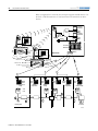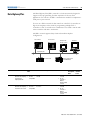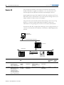
1
PLC-5 PROGRAMMABLE CONTROLLERS
SELECTION GUIDE 1785 and 1771
6 / 2011
www.klinkmann.com
6 / 2011
www.klinkmann.com
PLC-5 Programmable
Controllers Comparison
Category
Controller
Catalog Number
User Memory
Words, Max
Total I/O, Max
Number of
Communication
Ports (mode)
Standard
PLC-5/11
1785-L11B
8000
512
1 DH+ or Remote I/O
(Adapter or Scan)
PLC-5/20
1785-L20B
16,000
512
1 DH+ and 1 DH+ or
Remote I/O (Adapter or
Scan)
PLC-5/30
1785-L30B
32,000
1024
2 DH+ or Remote I/O
(Adapter or Scan)
PLC-5/40
1785-L40B
48,000
2048
4 DH+ or Remote I/O
(Adapter or Scan)
PLC-5/40L
1785-L40L
48,000
2048
2 DH+ or Remote I/O
(Adapter or Scan) and
1 Extended Local I/O
PLC-5/60
1785-L60B
64,000
3072
4 DH+ or Remote I/O
(Adapter or Scan)
PLC-5/60L
1785-L60L
64,000
3072
2 DH+ or Remote I/O
(Adapter or Scan) and
1 Extended Local I/O
PLC-5/80
1785-L80B
100,000
3072
4 DH+ or Remote I/O
(Adapter or Scan)
PLC-5/26
1785-L26B
16,000
512
1 DH+ and 1 DH+ or
Remote I/O (Adapter or
Scan)
PLC-5/46
1785-L46B
48,000
2048
4 DH+ or Remote I/O
(Adapter or Scan)
PLC-5/86
1785-L86B
100,000
3072
4 DH+ or Remote I/O
(Adapter or Scan)
PLC-5/20C
1785-L20C15
16,000
512
1 ControlNet (Dual
Media) and 1 DH+
PLC-5/40C
1785-L40C15
48,000
2048
1 ControlNet (Dual
Media) and 2 DH+ or
Remote I/O (Adapter or
Scan)
PLC-5/80C
1785-L80C15
100,000
3072
1 ControlNet (Dual
Media) and 2 DH+ or
Remote I/O (Adapter or
Scan)
ControlNet with
Protected Memory
PLC-5/46C
1785-L46C15
48,000
2048
1 ControlNet (Dual
Media) and 2 DH+ or
Remote I/O (Adapter or
Scan)
Ethernet
PLC-5/20E
1785-L20E
16,000
512
1 Ethernet, 1 DH+ and
1 DH+ or Remote I/O
(Adapter or Scan)
PLC-5/40E
1785-L40E
48,000
2048
1 Ethernet, 2 DH+ or
Remote I/O (Adapter or
Scan)
PLC-5/80E
1785-L80E
100,000
3072
1 Ethernet, 2 DH+ or
Remote I/O (Adapter or
Scan)
Standard with Protected
Memory
ControlNet
6 / 2011
www.klinkmann.com
Introduction
1
Introduction
1785 PLC-5 Programmable
Controller: The Foundation
of Control Architecture
The PLC-5 programmable controller stands at the center of a control
architecture that brings together existing and future systems by means of
networks such as EtherNet/IP, ControlNet and DeviceNet, and offers
connectivity among SLC 500, ControlLogix, and MicroLogix controllers.
Because they include embedded network connections, PLC-5 controllers
enable your control architecture to be flexible enough to include cost-effective
connections to a wide range of devices.
I/O Modules
Many Choices to Meet Your Exact
Requirements
Software Tools
Program in Structured Text, Function Block,
Sequential Function Charts or Ladder Logic
Languages
Controllers
Information, Control, and
Device Communication
Capability
Topic
PLC-5 System Overview
Lay Out the System
Select I/O Modules
Select Network Communications
Select Controllers
Select Chassis
Select Power Supplies
Select Software
ViewAnyWare Products
Summary
Page
2
4
7
19
31
37
39
43
50
53
Publication 1785-SG001B-EN-P - June 2006
6 / 2011
2
www.klinkmann.com
Introduction
PLC-5 System Overview
A PLC-5/1771 control system, at minimum, consists of a programmable
controller and I/O modules in a single 1771 chassis with a power supply. You
choose the controller with the on-board communication ports you need.
A simple system can consist of only a standalone controller and
I/O modules all in a single chassis.
PLC-5
Programmable
Controller
1771 I/O Chassis Backplane
1771 I/O modules in the
I/O chassis in which the
PLC-5 controller resides.
A maximum of 512 I/O.
On-board remote I/O scanner ports are available on all PLC-5 controllers.
On-board extended-local I/O scanner ports are available on some PLC-5
controllers. On-board ControlNet ports are available on some PLC-5
controllers. To provide a DeviceNet I/O scanner port to the system, you must
add a 1771-SDN DeviceNet Scanner Module.
Publication 1785-SG001B-EN-P - June 2006
6 / 2011
www.klinkmann.com
Introduction
3
In the typical configuration illustration, a ControlNet port on the controller
interfaces the processor to the ControlNet link. In each of the two chassis
remote from the controller, a 1771-ACN15 I/O Adapter Module provides
I/O modules in those chassis with an interface to the ControlNet link. In this
configuration, the PLC-5 controller monitors/controls the I/O in its local
I/O chassis as well as the I/O in the remote locations.
Multiple controllers can communicate across networks; and I/O in multiple platforms can be
distributed in many locations connected over multiple I/O links
• Computers
• Controllers
• Internet Browsers (Ethernet only)
• Ethernet
• ControlNet
• Data Highway Plus
• RS-232-C (DF1)
• Ethernet
Ethernet Interface
Module
DeviceNet Scanner
Module
1771 I/O Chassis Backplane
1771 I/O modules in the
I/O chassis in which the
PLC-5 controller resides.
A maximum of 512 I/O.
ControlNet Link
PLC-5
Programmable
Controller
DeviceNet Link
• 1734 I/O Modules
• 1769 I/O Modules
• 1790 I/O Blocks
• 1791D I/O Blocks
• 1792D I/O Blocks
• 1794 I/O Modules
• 1798 I/O Modules
• Other devices
• 1734 I/O Modules
• 1746 I/O Modules
• 1771 I/O Modules
• 1794 I/O Modules
• 1797 I/O Modules
• Other devices
Universal Remote I/O Link
• 1746 I/O Modules
• 1771 I/O Modules
• 1791 I/O Blocks
• 1794 I/O Modules
• Other devices
Extended-local I/O Link
• 1771 I/O Modules
Plug a 1771 power supply module into an I/O module slot, or connect a
standalone 1771 power supply into the left end of each chassis.
Depending on the communication ports available on your particular PLC
control system, you can select operator interfaces that are compatible with
those particular ports.
Publication 1785-SG001B-EN-P - June 2006
6 / 2011
4
www.klinkmann.com
Introduction
Lay Out the System
Lay out the system by determining the network configuration and the
placement of components in each location. Decide at this time whether each
location will have its own controller.
Place each controller’s I/O on an isolated network to maximize the
performance and to more easily accommodate future network or system
configuration changes. If you plan to share I/O, make sure the I/O is on a
network that each controller can access.
Assume that Network A and Network B both require a controller and its I/O.
Both controllers interact with time-critical information.
RSView
Network C
Panel C
Network B
Network A
Panel A
Chassis
Panel A
Chassis 2
Panel A
Chassis 3
Panel B
Chassis
Panel B
Chassis
Panel
View
Panel
View
For a PLC-5 controller to control I/O modules, both the controller and the
I/O modules must be directly attached to the same network.
I/O Location
Controller in
Panel A, Chassis 1
Controller in
Panel B, Chassis 1
Panel A, chassis 1
Yes
Yes
Panel A, chassis 2
Yes
No
Panel A, chassis 3
Yes
No
Panel B, chassis 1
Yes
Yes
Panel B, chassis 2
No
Yes
Panel C, chassis 1
Yes
Yes
Evaluate what communications need to occur between controllers. If there is
sporadic information that is not time-critical, use a message-based network
such as an EtherNet/IP (the information portion), Data Highway Plus, or the
unscheduled portion of the ControlNet network. If the information is
time-critical, such as producer/consumer tags between controllers, use the
ControlNet or EtherNet/IP network.
Publication 1785-SG001B-EN-P - June 2006
6 / 2011
www.klinkmann.com
Introduction
5
Apply Backup Solutions
The ControlNet Hot Backup Module, 1785-CHBM, provides backup of
ControlNet I/O. A secondary controller qualifies critical-control information
with the primary controller. Both controllers consume information from
inputs and connect to outputs, but only the primary controller controls the
outputs. The secondary controller establishes control of outputs if the primary
controller shuts down.
For more information, see page 23.
ControlNet PLC-5
Controller with 1785-CHBM
Cartridge Installed
PanelView Plus
or Other Interface
Device
ControlNet PLC-5
Controller with 1785-CHBM
Cartridge Installed
Redundant
ContolNet Network
1794 FLEX I/O
and/
or
and/
or
1746 I/O
1771 I/O
The PLC-5 Backup Communication Module, 1785-BCM, helps increase the
fault tolerance of PLC-5 programmable controller systems controlling I/O on
a remote I/O link by providing backup of the PLC-5 programmable
controller.
PLC-5 Controller
1785-BCM Module
PLC-5 Controller
1785-BCM Module
High-speed Serial Link
Local I/O Chassis
DH+ Link
Local I/O Chassis
Remote
I/O Link
DH+ Link
Remote I/O Chassis
Remote I/O Chassis
Terminator
1771-ASB Remote I/O Link
1771-ASB
Cat. No.
Connections
Customer Relay
Design Considerations
Power
Dissipation
Backplane Current
Load
1785-BCM
1771-WG wiring arm
(included)
0.25 A @ 24V dc (resistive)
Place in local I/O chassis
10 W max
1A
Publication 1785-SG001B-EN-P - June 2006
6 / 2011
6
www.klinkmann.com
Introduction
Use the following checklist as a guide to completing your own system
specification. The inside of the back cover of this selection guide is a
worksheet you can use to record your selections.
9
Step
1
For more information, see
Select I/O Modules
Select I/O based on:
• type of information to send/receive.
• application requirements.
• electrical requirements.
2
Select Network Communications
•
•
•
•
•
3
Select Networks based on:
type of information to send/receive.
system performance.
distance/size of application.
available networks.
future expansion.
Select Controllers
Select a controller based on:
• I/O requirements.
• memory requirements.
• communication requirements.
4
Select Chassis
Select a chassis based on:
• the number of slots you need.
5
Select Power Supplies
1771 I/O Modules ................................................. page 8
1746 I/O Modules ................................................. page 13
1794 I/O Modules ................................................. page 14
1797 I/O Modules ................................................. page 15
1791D I/O Modules............................................... page 16
1734 I/O Modules ................................................. page 17
NetLinx Architecture ............................................. page 19
Select a Network .................................................. page 20
EtherNet/IP Protocol.............................................. page 21
ControlNet ............................................................ page 23
DeviceNet............................................................. page 25
Serial Network...................................................... page 26
Data Highway Plus................................................ page 29
Remote I/O ........................................................... page 30
Enhanced Controllers............................................ page 32
Ethernet Controllers.............................................. page 33
ControlNet Controllers........................................... page 34
Protected Controllers ............................................ page 35
Backing Up Memory ............................................. page 36
Battery Replacement ............................................ page 36
1771 Chassis ....................................................... page 37
Mounting Dimensions ........................................... page 38
1771 Power Supplies............................................ page 39
Power Requirements and Transformer Sizing........ page 40
Select a power supply based on:
• input voltage.
• output current.
• number of slots required.
7
Select Software
Select software based on:
• computer platform.
• operating environment.
• programming language.
Publication 1785-SG001B-EN-P - June 2006
Select Software .................................................... page 43
Programming Software......................................... page 44
RSLinx Software ................................................... page 45
Network Configuration Software ........................... page 46
RSLogix Emulate 5 Software................................. page 47
PLC-5 and Training Software ................................ page 48
ViewAnyWare Products......................................... page 50
6 / 2011
www.klinkmann.com
Step 1 - Select:
•
•
•
•
•
•
•
1771 I/O Modules
1746 I/O Modules
1794 FLEX I/O Modules
1797 FLEX Ex I/O Modules
1791D CompactBlock I/O Modules
1734 POINT I/O Modules
Encompass Partner Program I/O
Modules
Select I/O Modules
7
Select I/O Modules
Rockwell Automation offers many types of I/O modules and has more than
3 million modules installed in applications worldwide. Rockwell Automation
offers chassis-based and both block and modular-distributed modules.
The following sections outline the available I/O modules. For more
information about these I/O modules, see the Allen-Bradley I/O Module
Brochure, publication ACIG-BR002, or visit the Rockwell Automation
Distributed I/O Web page at http://www.ab.com/io.
If your application requires preferred I/O for PLC-5, and
Use this type of I/O
On any of these networks
•
•
•
•
1771 I/O
see page 8
- ControlNet
- Remote I/O
- Extended Local I/O
If your application
Use this type of I/O
On any of these networks
• Is chassis-based and requires different types of I/O
• Has smaller size requirements than 1771
• Communicates with SLC controllers
1746 I/O
see page 13
- ControlNet
- Remote I/O
- Extended Local I/O
• Has distributed control that requires multiple types of I/O devices near
a machine
1794 FLEX I/O
see page 14
- EtherNet/IP
- ControlNet
- DeviceNet
- Remote I/O
- Extended Local I/O
- PROFIBUS DP
• Has distributed control in a hazardous area
1797 FLEX Ex I/O
see page 15
- ControlNet via coax or fiber
- DeviceNet via bus isolator
- EtherNet/IP via bus isolator
- PROFIBUS DP via bus isolator
• Requires rackless design with panel or DIN-rail mounting
• Requires modular, high-density I/O
1769 Compact I/O
see page 15
- DeviceNet
- Local I/O
• Has distributed control
• Must have I/O mounted near sensors or actuators
• Uses motor starters, solenoids, or indicators
1791D I/O CompactBlock I/O
see page 16
- DeviceNet
- Remote I/O
- PROFIBUS DP
• Requires high modularity
• Requires flexibility and low-cost of ownership
1734 POINT I/O
see page 17
- DeviceNet
- ControlNet
- EtherNet/IP
- PROFIBUS DP
• Requires functionality not delivered in Rockwell Automation products
Encompass Partners Program
products, see page 18
Multiple
Native I/O providing highest performance
Is chassis-based and needs to accommodate a wide range of I/O types
Controls an entire process
Is a master/slave configuration for distributed control
Publication 1785-SG001B-EN-P - June 2006
6 / 2011
8
www.klinkmann.com
Select I/O Modules
1771 I/O Modules
The 1771 series I/O modules offer digital, analog, and special-requirement
modules. The 1771 I/O modules feature a wide range of:
• signal interfaces to ac and dc sensors and actuators.
• I/O densities with as many as 32 I/O points per module.
• signal levels, including standard analog inputs and outputs and direct
thermocouple and RTD temperature inputs.
PLC-5 controllers support 1771 I/O over these networks:
•
•
•
•
Local I/O
Remote I/O
Extended-local I/O
ControlNet
When you select 1771 I/O modules, you must also select:
• Chassis
• Power supply
• Adapter module (if in remote chassis or extended-local chassis)
1771 Digital Input Modules
Category
Cat. No.
Inputs
and
Outputs
Voltage
Backplane
Current Load
TTL
1771-IG
8 in
--
122 mA
24V dc Sink
Source Load
48V dc Sink
Source Load
24V dc Source
Sink Load
24V ac
Publication 1785-SG001B-EN-P - June 2006
1771-IGD
16 in
--
130 mA
1771-IB
8 in
10...27V
74 mA
1771-IBD
16 in
10...30V
250 mA
1771-IBN
32 in
10...30V
280 mA
1771-IT
8 in
12...24V
74 mA
1771-IQ
8 in
5...30V
150 mA
1771-IQ16
16 in
10...32V isolated
100 mA
1771-IS
72 in
5V multiplexer
800 mA
1771-DW
7 in
15...27 wire fault
300 mA
1771-DS
8 in
10...27V latching
375 mA
1771-IC
8 in
42...56V
74 mA
1771-IH
8 in
24...50V
74 mA
1771-IV
8 in
12...24V
74 mA
1771-IVN
32 in
10...30V
280 mA
1771-IQ
8 in
5...30V
150 mA
1771-IQ16
16 in
10...32V isolated
100 mA
1771-IN
8 in
12...28V
80 mA
1771-IND
16 in
16...30V ac
9...30V dc
250 mA
6 / 2011
www.klinkmann.com
Select I/O Modules
Category
Cat. No.
Inputs
and
Outputs
Voltage
Backplane
Current Load
120V ac/dc
1771-ID
6 in
92...38V isolated
74 mA
1771-IAD
16 in
79...138V
195 mA
1771-ID16
16 in
77...138V ac
105...138V dc
isolated
75 mA
1771-IA
8 in
87...138V ac
97...138V dc
75 mA
120V ac
1771-IAN
32 in
85...138V
280 mA
220V ac/dc
1771-ID01
6 in
184...276V ac/dc
74 mA
1771-IM
8 in
184...276V ac/dc
75 mA
9
1771 Digital Output Modules
Category
Cat. No.
Inputs
and
Outputs
Voltage
Backplane
Current Load
TTL
1771-OG
8 in
5.0...5.3V
168 mA
1771-OGD
16 in
5.0...5.3V
230 mA
1771-OVN
32 out
10...30V
330 mA
1771-OQ16
16 out
10...32V isolated
400 mA
1771-OQ
8 out
20.4...26.4V isolated
225 mA
1771-OQ16
16 out
10...32V isolated
400 mA
1771-OB
8 out
10...27V
165 mA
1771-OBD
16 out
10...60V
300 mA
1771-OBN
32 out
10...30V
330 mA
48V dc Source
1771-OC
8 out
42...53V
165 mA
24V ac
1771-ON
8 out
20...30V
225 mA
120V ac
1771-OP
4 out
92...138V protected
350 mA
1771-OD
6 out
92...138 isolated
225 mA
1771-ODZ
8 out
92...138V isolated
350 mA
1771-ODD
16 out
85...138V isolated
420 mA
1771-OA
8 out
92...138V
210 mA
1771-OD16
16 out
74...138V isolated
200 mA
24V dc Sink
24V dc Source
1771-OAD
16 out
10...138V
295 mA
120/240V ac
1771-OAN
32 out
80...265V
800 mA
220V ac
1771-OR
6 out
184...276V isolated
255 mA
1771-OM
8 out
184...250V
225 mA
Publication 1785-SG001B-EN-P - June 2006
6 / 2011
10
www.klinkmann.com
Select I/O Modules
Category
Cat. No.
Inputs
and
Outputs
Voltage
Backplane
Current Load
24-120V ac/dc
Relay Contact
1771-OW
8 out
24...138V ac
resistive load
24-125V dc
700 mA
1771-OW16
16 out
24...250V ac
isolated
24...150V dc
isolated
1.3 A
1771-OWN
32 out
24...138V ac
24...125V dc
2.5 A
1771-OWNA
32 out
24...138V ac
resistive load
24-125V dc
2.5 A
1771-OX
4 out
0...250V ac isolated
inductive load
0...175V dc isolated
550 mA
1771-OYL
8 out
0...24V ac/dc
420 mA
1771-OZL
8 out
0...24V ac/dc
420 mA
0-24V ac/dc
1771 Analog Input Modules
Category
Cat. No.
Inputs and
Outputs
Range: Voltage and
Current
Backplane
Current Load
Selectable
1771-IFE
8 differential or
16 single
+10V dc
+20 mA
750 mA
1771-IFF
8 differential or
16_single
+10V dc
+20 mA
750 mA
1771-IL
8 differential,
isolated
+10V dc
+20 mA
1.3 A
1771-IE
8 single
+10V dc
500 mA
1771-NIV
8 in
+5V dc
+2 0mA
1.5 A
1771-NIV1
8 in
+10V dc
+20 mA
1.5 A
Voltage Only
1771-IFMS
8 differential
0...50 mV
750 mA
Current Only
1771-NIS
8 in isolated
4...20 mA
2.9 mA
Thermocouple
1771-IXE
8 floating
differential
+99.99 mV
750 mA
1771-IXHR
8 floating
differential
+99.99 mV
750 mA
1771-NT1
8 mV/TC
+100 mV
1.5 A
1771-NT2
8 mV/TC
-5/+55 mV dc
1.5 A
1771-IR
6 in
RTD
800 mA
1771-NR
8 in
RTD isolated
1.5 A
1771-NIVR
4V/current in
+5V dc
+20 mA
1.5 A
1771-NIVT
4V/current and
4 mV/TC in
+5V dc for volt/current
+20 mA
+100 mV for mV/TC
1.5 A
RTD
Mixed
Publication 1785-SG001B-EN-P - June 2006
6 / 2011
www.klinkmann.com
Select I/O Modules
11
1771 Analog Output Modules
Category
Cat. No.
Inputs and
Outputs
Range: Voltage
and Current
Backplane
Current Load
Selectable
1771-OFE1
4 out
+10V dc
1.5 A
Current Only
Voltage Only
1771-OFE2
4 out
4...20 mA
1.5 A
1771-OFE3
4 out
0...50 mA
2.5 A
1771-NOC
8 out
0...25 mA
2.9 A at 20 mA
3.3 A at 25 mA
1771-NOV
8 out
+10V dc
2.1 A
1771 Analog Combination Modules
Category
Cat. No.
Inputs and
outputs
Range: Voltage
and Current
Backplane
Current Load
Selectable
Voltage
1771-NBV1
6 in
2 out
+10V dc
+20 mA
1.8 A
Selectable
Current
1771-NBVC
6 in
2 out
+5V dc/+20mA
0...25 mA
1.8 A
Current
1771-NB4S
2 in
2 out isolated
4...20 mA
0...25 mA
1.6 A
1771-NBSC
6 in
2 out isolated
4...20 mA
0...25 mA
3.0 A
1771-NB4T
2 in
2 out
mV/TC +100 mV
0...25 mA
1.5 A
1771-NBRC
6 in
6 out
RTD
0...25 mA
1.8 A
1771-NBTC
6 in
2 out
mV/TC +100 mV
0...25 mA
1.6 A
RTD
Publication 1785-SG001B-EN-P - June 2006
6 / 2011
12
www.klinkmann.com
Select I/O Modules
1771 Intelligent Modules
Category
Cat. No.
Use
Backplane Current
Load
Counter
1771-IJ
Incremental encoder/counter
1.2 A
Positioning
1771-IK
High-speed counter
1.2 A
1771-VHSC
Very high speed counter
0.65 A
1771-DE
Absolute encoder
0.8 A
1771-DL
Gray encoder
0.12 A
1771-QA
Stepper motor positioning
0.8...2.4 A
1771-QB
Linear positioning
1.6 A
1771-QC
Servo positioning
1.75 A
1771-M3
Servo controller
1.75 A
1771-ES
Servo encoder feedback expander
1.7 A
1771-M1
Stepper motor controller
1.75 A
1771-QD
Injection molding
0.5 A
1771-QDC
Plastic molding
1.2 A
1771-QH
Force control
1.2 A
1771-HS
IMC 120 motion control
0.72 A
1771-HS1
IMC 121 motion control
1.06 A
1771-HS3
IMC 123 motion control
1.06 A
1771-HRA
Resolver excitation
0.065 A
Flow
1771-CFM
Configurable flowmeter
1.0 A
Specialty
1771-PM
Clutch/brake control
1.2 A
1771-SIM
I/O simulator
0.2 A
1771-DR
High-speed logic
1.1 A
1771-PD
PID control
1.2 A
1771-DC
Real-time clock
1771-DB
BASIC
1771-LC
Loop control
1771-TCM
Temperature control
1.5 A
Temperature
0.65 A without
DH-485
0,75 A with DH-485
Hydraulic
1771-QH
High-speed transparent transition
1.2 A
Plastics
1771-QDC
Plastic molding
1.2 A
1771-QI
Co-injection
1.2 A
For more information about the family of 1771 I/O modules, see the
following publications.
Publication 1785-SG001B-EN-P - June 2006
Publication Title
Publication Number
1771 Digital I/O ac Input and Output Modules Product Data
1771-2.182
1771 Analog Input and Output Modules Product Data
1771-2.183
1771 Digital I/O dc Input and Output Modules Product Data
1771-2.180
6 / 2011
www.klinkmann.com
1746 I/O Modules
Select I/O Modules
13
The 1746 I/O modules (SLC 500 I/O) provide a cost-effective, Remote I/O
option. Use an SLC 500 Remote I/O module (1747-ASB) or ControlNet
adapter module (1747-ACN15 or -ACNR15) to directly interface 1746 I/O
modules to the PLC-5 system. The 1746 I/O modules feature:
• high-density, 32-point and combination modules, which reduce rack size
and panel space requirements.
• removable terminal blocks and 16-point modules, which simplify wiring
and replacing modules.
• industrial design, including input filtering and optical isolation.
PLC-5 controllers support 1746 I/O over these networks:
• Remote I/O
• ControlNet
When you select 1746 I/O modules, you must also select:
•
•
•
•
Chassis
Power supply
Cabling components
Adapter module, if in remote chassis or extended-local chassis
For more information, see the following publications.
Publication Title
Publication Number
SLC 500 System Overview
1747-SG001
SLC Analog I/O Modules Technical Data
1746-TD001
SLC Modular Chassis and Power Supplies Technical Data
1746-TD003
Publication 1785-SG001B-EN-P - June 2006
6 / 2011
14
www.klinkmann.com
Select I/O Modules
1794 FLEX I/O Modules
FLEX I/O is a cost-effective, flexible, modular I/O system for distributed
applications and offers all the functions of larger rack-based I/O without the
space requirements. You can independently select the I/O type, termination,
and network, appropriate for your specific application. This means one I/O
product line can fit all your needs. The 1794 FLEX I/O modules feature:
• modular design, which reduces costs by solving a large range of
application requirements with one I/O architecture.
• small size, which reduces packaging costs.
• individual wire-termination locations, which reduce purchasing costs
and complexity, as well as packaging costs.
• diagnostics and removal and insertion under power (RIUP), which
lowers the mean time to repair equipment and leverages your control
investment.
• flexible communications, which helps to control future costs by
providing an economical migration path.
PLC-5 controllers support 1794 I/O over these networks:
• Remote I/O
• ControlNet
• DeviceNet
For more information about 1794 FLEX I/O, see the FLEX I/O and FLEX
Ex I/O Selection Guide, publication 1794-SG002.
Publication 1785-SG001B-EN-P - June 2006
6 / 2011
www.klinkmann.com
1797 FLEX Ex I/O Modules
Select I/O Modules
15
The 1797 series I/O modules (FLEX Ex I/O) are a flexible I/O system that
mounts directly to the controlled equipment in a hazardous area. This
eliminates the need for intrinsically safe (IS), barriers/isolators and separation
of control and process. Additionally, the modules:
• offer modularity for distributed intrinsically-safe systems.
• have dual-fault protection IS circuits that provide high fault tolerance.
• have I/O circuitry that provides full IS field-device protection.
PLC-5 controllers support 1797 I/O over these networks:
• Remote I/O
• ControlNet
• DeviceNet
When you select 1797 FLEX Ex I/O modules, you must also select:
•
•
•
•
•
adapter module and cabling components.
bus isolator module and cabling components.
terminal base unit.
DIN rail.
power supply.
For more information about 1797 FLEX Ex I/O, see the FLEX I/O and
FLEX Ex I/O Selection Guide, publication 1794-SG002.
Publication 1785-SG001B-EN-P - June 2006
6 / 2011
16
www.klinkmann.com
Select I/O Modules
1791D CompactBlock I/O
Modules
The 1791D I/O modules (CompactBlock I/O) are designed for applications
that require I/O to be distributed close to sensors and actuators or to be
placed in small enclosures. The modules feature:
• self-contained package that provides cost-effective distribution of up to
32 points per node.
• small size that lets you install in shallow and confined areas.
• hardware watchdog circuit.
• DeviceLogix Smart Component Technology that provides limited I/O
logic for intelligent I/O block.
PLC-5 controllers support 1791D I/O over these networks:
• Remote I/O
• DeviceNet
• PROFIBUS DP
When you select 1791D I/O modules, the I/O circuits, a built-in power
supply, and a Remote I/O adapter are included. You must select an enclosure
and cabling components.
For more information about 1791D CompactBlock I/O, see the 1791D Block
I/O Technical Data, publication 1791D-TD001.
Publication 1785-SG001B-EN-P - June 2006
6 / 2011
www.klinkmann.com
1734 POINT I/O Modules
Select I/O Modules
17
POINT I/O is a family of I/O modules that are ideal for applications where
flexibility and low-cost of ownership are key for successful control system
design and operation. POINT I/O can be used in remote device panels, local
control panels, and can be accessed from many locations including the
Internet. This product is just-what-you-need granularity in one to eight points
to reduce system cost and size. POINT I/O modules feature:
•
•
•
•
•
•
•
A highly modular design with 1 point to 8 point modularity
Broad application coverage
Parameter-level explicit messaging
Removal and insertion under power
Channel-level open-wire detection with electronic feedback
Robust backplane design
Built-in DIN-rail grounding
PLC-5 controllers support POINT I/O over these networks:
• DeviceNet
• ControlNet
• PROFIBUS DP
When you select POINT I/O modules, you must also select:
•
•
•
•
A communication interface
I/O devices based on field devices
Wiring base assembly
Power distribution modules
For more information about POINT I/O, see the POINT I/O Selection
Guide, publication 1734-SG001.
Publication 1785-SG001B-EN-P - June 2006
6 / 2011
18
www.klinkmann.com
Select I/O Modules
Additional I/O Selections
The Encompass Partners Program, Rockwell Automation’s third-party
product referencing program, builds on the strengths of our products.
As a technology-sharing program, Encompass is product-based and
application-focused. Encompass allows third-party companies to provide
functionality not delivered in Rockwell Automation products. The following
table lists additional I/O choices that are part of the Encompass program.
Encompass Partner
Products
Advanced Micro Controls, Inc.
• 1771 LDT Interface Module
• 1771 Programmable Limit Switch
• 1771 Resolver Interface Module
Ametek Automation and Process
Technologies
Gemco Series 1771 Programmable Limit
Switch
Hardy Instruments
1771-WS Weigh Scale Module
Hiprom Ltd.
1771 GPS Time Stamp Module
Miille Applied Research Company, Inc.
Dial Up and Leased Line Modems and
Protocol Converters
Phoenix Digital Corporation
Optical Comm Modules for:
• Ethernet
• ControlNet
• DF-1
• Data Highway
• DH-485
• Modbus
• RS-232
• RS-485
ProSoft Technology, Inc.
•
•
•
•
•
•
•
Spectrum Controls, Inc.
• High-density 32 Analog Input Module
• 200V ac/dc Isolated 16 Input Module
• 120/240V ac Isolated 16 Output Module
Weed Instrument
Fiber Optic Modems
Woodhead
PLC-5 Scanners for PROFIBUS DP
“C” Programmable Solutions
AGA/API Flow Computers
HART
Honeywell DE Interface
Modbus Plus Communications-PLC
PLC Protocol Solutions
PLC Protocol Solutions-MVI
For more detailed information, refer to the Encompass product directory,
publication 6873-QR004, or see www.rockwellautomation.com/encompass.
Publication 1785-SG001B-EN-P - June 2006
6 / 2011
www.klinkmann.com
Step 2 - Select:
• EtherNet/IP Protocol
• ControlNet Network
• DeviceNet Network
• Serial Network
• Data Highway Plus
• Remote I/O
Select Network Communications
19
Select Network Communications
Use specific PLC-5 controllers with network connections and install multiple
communication modules into the PLC-5 backplane to route control and
information data between the different networks.
The networking capabilities, led by EtherNet/IP, ControlNet, and DeviceNet
networks, allow information exchange between a range of devices and
computing platforms and operating systems. PLC-5 controllers come with
different network connections. Choose the network that best meets your
needs.
NetLinx Architecture
NetLinx open network architecture is the Rockwell Automation strategy of
using open networking technology for seamless, top-floor to shop-floor
integration. The networks in the NetLinx architecture - DeviceNet network,
ControlNet network and EtherNet/IP network - speak a common language
and share a universal set of communication services. NetLinx architecture, part
of the Integrated Architecture, seamlessly integrates all the components in an
automation system from a few devices on one network to multiple devices on
multiple networks including access to the Internet - helping you to improve
flexibility, reduce installation costs, and increase productivity.
• EtherNet/IP network is an open industrial networking standard that
supports implicit and explicit messaging and uses commercial,
off-the-shelf Ethernet equipment and physical media.
• ControlNet network allows intelligent, high-speed control devices to
share the information required for supervisory control, work-cell
coordination, operator interface, remote device configuration,
programming, and troubleshooting.
• DeviceNet network offers high-speed access to plant-floor data from a
broad range of plant-floor devices and a significant reduction in wiring.
Publication 1785-SG001B-EN-P - June 2006
6 / 2011
20
www.klinkmann.com
Select Network Communications
Select a Network
Configure your system for information exchange between a range of devices
and computing platforms and operating systems.
If your application requires
Use this network
Select
• High-speed data transfer between information systems and/or a large
quantity of controllers
• Internet/intranet connection
• Program maintenance
EtherNet/IP
•
•
•
•
• High-speed transfer of time-critical data between controllers and
I/O devices
• Deterministic and repeatable data delivery
• Program maintenance
• Media redundancy or intrinsic safety options
ControlNet
• 1785-L20C15
• 1785-L40C15
• 1785-L80C15
• Connections of low-level devices directly to plant floor controllers,
without the need to interface them through I/O modules
• More diagnostics for improved data collection and fault detection
• Less wiring and reduced start-up time than a traditional,
hard-wired system
DeviceNet
PLC-5 controller with
1771-SDN scanner module
• Plant-wide and cell-level data sharing with program maintenance
Data Highway Plus
All PLC-5 controllers have at
least one built-in,
configurable Data Highway
Plus channel
• Connections between controllers and I/O adapters
• Distributed controllers so that each controller has its own I/O and
communicates with a supervisory controller
Remote I/O
All PLC-5 controllers have at
least one built-in,
configurable remote I/O
channel
• Modems
• Messages that send and receive ASCII characters to or from devices
such as ASCII terminals, bar-code readers, message displays, weigh
scales, or printers
• Supervisory control and data acquisition (SCADA)
Serial Network
All PLC-5 controllers have
one built-in serial port
configurable for RS-232,
RS-423, or RS-422A
Publication 1785-SG001B-EN-P - June 2006
1785-L20E controller
1785-L40E controller
1785-L80E controller
Applicable PLC-5
controller with 1785-ENET
interface module
6 / 2011
www.klinkmann.com
Select Network Communications
21
Ethernet/IP protocol is an open industrial-networking standard that supports
implicit messaging (real-time I/O messaging), explicit messaging (messaging
exchange), or both and uses commercial off-the-shelf Ethernet
communication chips and physical media.
EtherNet/IP Protocol
Additionally, EtherNet/IP standard uses the protocols used by the Internet.
Both the PLC-5 and Ethernet Interface Module (1785-ENET) contain
features that let you to use the Internet to access product information and to
create and enhance application diagnostics.
Ethernet PLC-5 Controllers
Cat. No.
1785-L20E
User
Memory
(words),
Max
16,000
1785-L40E
48,000
1785-L80E
100,000
Total I/O, Max
Channels
Number of I/O Chassis, Max
Cable
Total Extended Remote ControlNet
-local
512 any mix or
512 in + 512 out
(complement)
2048 any mix or
2048 in + 2048 out
(complement)
3072 any mix or
3072 in + 3072 out
(complement)
1 Ethernet
1 DH+
1 DH+/remote I/O
1 Ethernet
2 DH+/remote I/O
13
0
12
0
61
0
60
0
1 Ethernet
2 DH+/remote I/O
65
0
64
0
Power
Backplane
Dissipation, Current
Max
Load
5810-TC02 18.9 W
or
5810-TC15
5810-TC02 18.9 W
or
5810-TC15
5810-TC02 18.9 W
or
5810-TC15
3.6 A
3.6 A
3.6 A
Laptop
Internet
Server
Workstation
Personal Computer
Modem
PLC-5/20E
Controller
SLC 5/05
Controller
Ethernet
PLC-5 Controller
with Ethernet
Interface
Module
ControlLogix
Gateway or
Logix5550
Controller
ControlLogix
Gateway
PLC-5 Controller
Data Highway Plus
ControlNet
Publication 1785-SG001B-EN-P - June 2006
6 / 2011
22
www.klinkmann.com
Select Network Communications
PLC-5 Ethernet Interface Module
The PLC-5 Ethernet Interface Module (1785-ENET) is a single-slot module
that attaches to the side of any Enhanced PLC-5 series B or later controller,
Ethernet PLC-5 controller, or ControlNet PLC-5 controller to provide
additional Ethernet connectivity.
Cat. No.
When used with
The interface module provides
1785-ENET
Ethernet PLC-5 controller
Additional Ethernet connectivity by
supporting dual Ethernet links
Enhanced PLC-5 controller
Ethernet connectivity without sacrificing
DH+ or remote I/O ports
ControlNet PLC-5
controller
Dedicated Ethernet connectivity for plant
and office integration
Using the Ethernet Interface Module’s built-in communication capabilities,
your entire enterprise can use standard Ethernet or Internet connectivity to
control and monitor production. Using the Internet and Web browser, you can
create your own custom Web pages to provide executive summaries of process
information. These pages are accessible to any Internet user who has network
access to the PLC-5 controller. The embedded Web server provides access to
PLC-5 diagnostics. Domain Name Service (DNS) and Simple Network
Management Protocol (SNMP) are also supported.
Cat. No.
Comm.
Rate
1785-ENET 10/100
Mbps
Connections
Design Considerations
64 TCP/IP connections
Place in I/O chassis second leftmost slot
512 unsolicited definitions per module attached to controller
Publication 1785-SG001B-EN-P - June 2006
Power
Dissipation, Max
Backplane Current
Load
11.5 W
2.2 A
6 / 2011
www.klinkmann.com
ControlNet Network
Select Network Communications
23
ControlNet PLC-5 controllers offer embedded ControlNet communication
capabilities for control and information processing. The ControlNet network
provides both I/O control and peer-to-peer communications on a 5 Mbps
network, with repeatability and determinism.
You can have multiple ControlNet PLC-5 controllers on one ControlNet
network, with each controller handling its own I/O on the network, and at the
same time communicating with each other. Multiple controllers can receive
input data from one I/O or device node.
ControlNet PLC-5 Programmable Controllers
Cat. No.
User
Memory
(words),
Max
Total I/O Max
1785-L20C15
16,000
512 any mix or
512 in + 512 out
(complement)
1785-L40C15
48,000
1785-L46C15
Protected
1785-L80C15
Channels
Number of I/O Chassis,
Max
Total Extended Remote
-local
1 ControlNet
1 DH+
1 DH+/remote I/O
ControlNet Cable
I/O Map
Entries
Power
Dissipation,
Max
Backplane
Current
Load
77
0
12
64
1786-CP
15.8 W
3.0 A
1 ControlNet
2048 any mix or
2048 in + 2048 out 2 DH+/remote I/O
(complement)
125
0
60
96
1786-CP
15.8 W
3.0 A
48,000
1 ControlNet
2048 any mix or
2048 in + 2048 out 2 DH+/remote I/O
(complement)
125
0
60
96
1786-CP
15.8 W
3.0 A
100,000
3072 any mix or
1 ControlNet
3072 in + 3072 out 2 DH+/remote I/O
(complement)
125
0
92
128
1786-CP
15.8 W
3.0 A
Workstation Running
Programming Software
with 1784-KTCx
ControlNet
FLEX I/O Adapter
PanelView 1200
Operator Terminal
ControlLogix Gateway or
Logix5550 Controller
PLC-5/40C Controller
1395 Drive
Publication 1785-SG001B-EN-P - June 2006
6 / 2011
24
www.klinkmann.com
Select Network Communications
ControlNet Communication Adapters
Cat. No.
Function
1734-ACNR
Interfaces POINT I/O modules in a
POINTBus backplane to ControlNet
controllers across a ControlNet network
1747-ACN15,
Interfaces SLC I/O modules in an SLC
-ACNR15
chassis to a ControlNet scanner port
across a ControlNet network
1771-ACN15,
Interfaces 1771 I/O modules in a 1771
-ACNR15
chassis to a ControlNet scanner port
across a ControlNet network
1794-ACN15,
Interfaces FLEX I/O modules in a FLEX
-ACNR15
I/O rack to a ControlNet scanner port
across a ControlNet network
1797- -ACNR15 Interfaces FLEX Ex I/O modules in a
FLEX Ex rack to a ControlNet scanner
port across a ControlNet network
Comm.
Rate
Design Considerations
Cable
5 Mbps
Requires a remote ControlNet
PLC-5 controller, Series F,
Revision E, or later.
Requires a remote ControlNet
PLC-5 controller.
Quad shield RG-6
coaxial cable
5 Mbps
5 Mbps
5 Mbps
5 Mbps
Power
Dissipation,
Max
5.0 W
Backplane
Current
Load
1.0 A
Quad shield RG-6
coaxial cable
5W
900 mA
Place in remote ControlNet
chassis. Requires a ControlNet
PLC-5 controller.
Requires a remote ControlNet
PLC-5 controller.
Quad shield RG-6
coaxial cable
5.2 W
1.0 A
Quad shield RG-6
coaxial cable
4.6 W
640 mA
Requires a remote ControlNet
PLC-5 controller.
Quad shield RG-6
coaxial cable
8.5 W
640 mA
ControlNet Hot Backup Module
The ControlNet Hot Backup Module provides backup of ControlNet I/O.
A secondary controller qualifies critical control information with the primary
controller. Both controllers consume information from inputs and connect to
outputs, but only the primary controller controls the outputs. The secondary
controller establishes control of outputs if the primary controller shuts down.
ControlNet Hot Backup Basic System
Cat. No.
1785-CHBM
1785-L40C15/F or 1785-L80C15/F(1)
1771-A1B through 1771-A4B
1771-P4 through 1771-P10
1771-ACN(R)15, 1747-ACN(R), or
1794-ACN(R)
1784-KTCX15 or 1784-PCC card
9234 Series
9357-CNETL3
9234 Series
Other System Requirements
(1)
Quantity
2
2
Description
ControlNet Hot Backup Modules
ControlNet PLC-5 Programmable Controllers, Series F or later
2
2
1
1771 I/O Chassis
1771 Power Supplies
ControlNet Adapter
1
Communication card for personal computer or laptop computer
1
RSLogix 5 Programming Software, version 3.22 or later
1
RSNetWorx for ControlNet Software, version 1.80.xx or later
1
RSLinx Gateway Communication Software, version 2.00.97.30 or later
ControlNet network cables, taps, and terminators for connections between the PLC-5 controllers and I/O adapters
Both controllers must have the same series and firmware revision.
PanelView Plus or Other
Interface Device
ControlNet PLC-5
Controller with 1785-CHBM
Cartridge Installed
1794 FLEX I/O
Redundant
ContolNet Network
and/
or
and/
or
1746 I/O
Publication 1785-SG001B-EN-P - June 2006
ControlNet PLC-5
Controller with 1785-CHBM
Cartridge Installed
1771 I/O
6 / 2011
www.klinkmann.com
Select Network Communications
25
The 1771-SDN DeviceNet scanner module acts as an interface between
DeviceNet devices and a PLC-5 controller. The scanner module
communicates with DeviceNet devices over the network to:
DeviceNet Network
• read and write inputs and outputs to and from a device.
• download configuration data to a device.
• monitor operational status of a device.
The scanner module is a single-slot module that resides in a 1771 I/O chassis
that either contains a PLC-5 controller or is on an extended-local I/O link,
remote I/O link, or ControlNet network connected to a PLC-5 controller. The
scanner module has Auto Device Replacement, change of state, cyclic I/O,
pass-through, and Slave mode capability.
The number of PLC DeviceNet scanners that can reside in the same I/O
chassis is limited only by the I/O chassis size, power supply capacity, and
available memory.
Cat. No.
Function
Comm.
Rate
1771-SDN
Interfaces a local PLC-5
controller to a max of 2
DeviceNet networks
125 Kbps 63 connections per
250 Kbps DeviceNet channel
500 Kbps
Connections
Design Considerations
Cable
Place in the local I/O
chassis
1771-CD
6.3 W
10-pin linear plug,
1787-PLUG10R
PLC-5 Controller with
1771-SDN Scanner Module
Power
Backplane
Dissipation, Current
Max
Load
1.2 A
Logix5550 Controller with
1756-DNB Module
DeviceNet
Other
Devices
Sensor
Push button Cluster
Motor
Starter
Laptop
Input/output
Devices
Indicator
Lights
Bar Code
Scanner
Drive
Publication 1785-SG001B-EN-P - June 2006
6 / 2011
26
www.klinkmann.com
Select Network Communications
The PLC-5 serial port is configurable for RS-232, RS-423, or RS-422A
compatible serial communication. Use the serial port to connect devices that:
Serial Network
• communicate using the DF1 protocol, such as modems, communication
modules, programming workstations, or other serial devices.
• send and receive ASCII characters, such as ASCII terminals, bar-code
readers, and printers.
When configured for System mode, the serial port supports the DF1 protocol.
Use System mode to communicate with others devices on the serial link.
Use This DF1 Mode
For
Point-to-point
• Communication between a PLC-5 controller and other
DF1-compatible devices.
• In Point-to-Point mode, the PLC-5 controller uses DF1
full-duplex protocol.
DF1 Master
• Control of polling and message transmission between the
master and each remote node.
• In Master mode, the PLC-5 controller uses DF1 half-duplex
polled protocol.
DF1 Slave
• Using the controller as a slave station in a master/slave serial
network.
• In Slave mode, the PLC-5 controller uses DF1 half-duplex
protocol.
The serial port, in System mode, also supports supervisory control and data
acquisition (SCADA) applications. SCADA systems let you monitor and
control remote functions and processes using serial communication links
between master and slave locations.
(1)
Cat. No.
Function
Comm.
Rate
1771-DA
Interfaces a PLC-5
controller and a
peripheral device that
generates ASCII
characters
Configurable, RS-232-C
depending
Current loop, 20 mA
on serial
protocol
Connections
Design Considerations
Cable
Power
Backplane
Dissipation, Current
Max
Load
Place in the local I/O
chassis
Custom 26-pin
cable(1)
6.8 W
See the Enhanced and Ethernet PLC-5 Programmable Controllers User Manual, publication 1785-UM012.
Publication 1785-SG001B-EN-P - June 2006
1.3 A
6 / 2011
www.klinkmann.com
Select Network Communications
27
The PLC BASIC Module occupies one slot in the 1771 I/O chassis and runs
user-written BASIC and C programs. These programs are independent of your
PLC-5 controller and provide an easy and fast interface between a PLC-5
controller, 1771 backplane, and RS-232, -422, or -485 devices. The module can
also communicate with a remote SLC controller or remote device on the
DH-485 network through a DH-485 port.
Cat. No.
Function
Comm.
Rate
1771-DB
Provides an interface
between a PLC-5
controller, 1771
backplane, and RS-232,
-422, or -485 devices
Configurable, • 2 ports for RS-232, Place in the local I/O
depending on
-422, or -485
chassis
serial protocol • 1 port for DH-485
Connections
Design Considerations
Cable
• Data
Highway
1770-CD
• RS-232
1770-CG
or Modem
Interface
Cable
1770-CP
Power
Dissipation,
Max
4W
Backplane
Current
Load
0.75 A (with
1747-PIC)
0.65 A
The communication controller modules, 1771-KE and 1771-KF, link
intelligent RS-232-C devices to Data Highway. Both of these modules provide
a choice of two protocols on the RS-232-C link - full-duplex and half-duplex.
These modules perform the same functions, however their mounting styles
and power supply requirements are different.
Cat. No.
Function
Comm.
Rate
Connections
Design Considerations
1771-KE
Provides an interface
between RS-232-C
devices and Data
Highway link with both
full-duplex and
half-duplex protocols
• Data
Highway 57 Kbps
• RS-232-C
from 110 to
19 Kbps
Data Highway,
RS-232
Place in the local I/O
chassis. Power source is
the 1771 I/O chassis
power supply.
1771-KF
Provides an interface
between RS-232-C
devices and Data
Highway link with both
full-duplex and
half-duplex protocols
• Data
Highway 57 Kbps
• RS-232-C
from 110 to
19 Kbps
Data Highway,
RS-232
Cable
Power
Dissipation,
Max
6.3 W
• Data Highway
1770-CD
• RS-232
1770-CG or
Modem
Interface Cable
1770-CP
Includes mounting
• Data Highway 6.3 W
bracket for external
1770-CD
mounting or in a standard • RS-232
industrial enclosure
1770-CG or
(NEMA Type 12 or
Modem
similar). Power source is
Interface Cable
user-supplied (1771-P2 or
1770-CP
similar).
Backplane
Current
Load
1.2 A
1.2 A
Publication 1785-SG001B-EN-P - June 2006
6 / 2011
28
www.klinkmann.com
Select Network Communications
When configured for User mode, the serial port supports ASCII devices. Use
the PLC-5 ASCII instructions to send and receive information from these
devices.
Computer
Workstation
Server
Computer
Workstation
DCE
Remote Station
Ethernet
Modem
PLC-5/40E
Workstation
Remote Station
Modem
Master Station
Oil Well
Modem
Gas Well
Remote
Station
Remote
Station
Unloading Storage
Facility
Storage
Tanks
Tank
Farm
Unloading Dock
Mainline
Pump Station
Remote
Station
Remote
Station
Refinery
Storage
Storage
Tanks
Remote
Station
Mainline
Pump Station
Storage
Tanks
Remote
Station
Storage/
Delivery Facility
Storage
Tanks
Metered
Truck Rack
20031-M
Publication 1785-SG001B-EN-P - June 2006
6 / 2011
www.klinkmann.com
Select Network Communications
29
The Data Highway Plus (DH+) network is a local area network designed to
support remote programming and data acquisition for factory-floor
applications. You can also use DH+ communication modules to implement a
small peer-to-peer network.
Data Highway Plus
You can use a DH+ network for data transfer to other PLC-5 controllers or
high-level computers and as a link for programming multiple PLC-5
controllers. A PLC-5 controller can communicate over a DH+ network with
other controllers and with a workstation.
The DH+ network supports daisy-chain and trunkline-dropline
configurations.
PLC-5 Controller
PLC-5 Controller
Workstation
Workstation with
RSLogix 5 Software
Data Highway Plus
SLC-5/04 Controller
Cat. No.
Function
1785-KA
1785-KE
Comm.
Rate
ControlLogix Chassis with
1756-DHRIO Module
Connections
Design Considerations
Cable
Power
Dissipation,
Max
10.5 W
• DH+ 57 Kbps
Provides an interface
between Data Highway • DH-485
Plus and Data
configurable
Highway-485 link
DH+
DH-485
• DH+ 57 Kbps
Provides an interface
between Data Highway • RS-232-C
Plus and RS-232-C link
configurable
DH+
RS-232-C
Place in the local chassis • Data Highway
1770-CD
• RS-232
1770-CG or
Modem
Interface Cable
1770-CP
Place in the local chassis • Data Highway 6.3 W
1770-CD
• RS-232
1770-CG or
Modem
Interface Cable
1770-CP
Backplane
Current
Load
2.0 A
1.2 A
Publication 1785-SG001B-EN-P - June 2006
6 / 2011
30
www.klinkmann.com
Select Network Communications
The strength and versatility of the remote I/O network comes from the
breadth of products it supports. In addition to 1771 I/O, the remote I/O
network supports many Rockwell Automation and third-party devices.
Remote I/O
Typical applications range from simple I/O links with controllers and I/O, to
links with a variety of other devices. You connect devices through remote I/O
adapter modules or built-in remote I/O adapters.
Using the remote I/O network instead of direct-wiring a device over a long
distance to a local I/O chassis helps reduce installation, startup, and
maintenance costs by placing the I/O closer to the sensors and actuators.
Some devices, like PLC-5 support Pass-Through, let you configure devices on
a remote I/O network from an Ethernet, ControlNet, or Data Highway Plus
network.
Workstation with
PanelBuilder Software
ControlNet, EtherNet/IP, or DH+ Network
PLC-5 Controller
Remote I/O Link
FLEX I/O Adapter
1771 I/O Adapter
Cat. No.
1771-ASB
Function
Interfaces I/O modules in
an I/O chassis to a
remote scanner port
across a remote I/O link
1771-DCM Provides a remote I/O
adapter port for a local
PLC-5 controller to
communicate with a
remote I/O scanner port
of a supervisory process
across a remote I/O link
SLC I/O Adapter
PanelView 1200
Operator Terminal
Comm.
Rate
Connections
Design Considerations
57.6 Kbps
115 Kbps
230 Kbps
Remote I/O
adapter port
57.6 Kbps
115.2 Kbps
Remote I/O
adapter port
Place in a remote chassis. 1770-CD
Requires a PLC-5
Belden 9463
controller that supports
remote I/O
Place in the local chassis 1770-CD
Belden 9463
Publication 1785-SG001B-EN-P - June 2006
Cable
Power
Dissipation,
Max
5.2 W
Backplane
Current
Load
1.0 A
6.3 W
1.2 A
6 / 2011
31
www.klinkmann.com
Select Controllers
Step 3 - Select:
•
•
•
•
•
•
Enhanced PLC-5 Controllers
Ethernet PLC-5 Controllers
ControlNet PLC-5 Controllers
Protected PLC-5 Controllers
EEPROM Memory Modules
Replacement Batteries
Select Controllers
PLC-5 controllers are high-speed, single-slot controllers you can use for
control and information processing. PLC-5 controllers are designed for larger
sequential and regulatory control applications with specialized I/O
requirements and/or the need to coordinate with other controllers and
devices.
PLC-5 controllers come with different memory sizes and network
connections. The Enhanced PLC-5 controllers offer a standard set of
functions and communication options. The other PLC-5 controllers offer
different communication options, while maintaining the same functions.
Choose the controller that best meets your needs.
Publication 1785-SG001B-EN-P - June 2006
If your application requires
Select from
• Connectivity to a large number of Remote I/O devices
• Connectivity to a large number of DH+ devices
Enhanced PLC-5 Controllers
see page 32
• EtherNet/IP connectivity
• Communication with other Ethernet PLC-5 controllers and
host computers
Ethernet PLC-5 Controllers
see page 33
• High-speed communication for control and
information processing
• Deterministic, repeatable data transfers
• ControlNet connectivity
ControlNet PLC-5 Controllers
see page 34
• Limited access to critical or proprietary areas of programs
• Selectively access to processor memory and I/O elements
• Restricted use of processor operations
Protected PLC-5 Controllers
see page 35
6 / 2011
32
www.klinkmann.com
Select Controllers
Enhanced PLC-5 Controllers
Cat. No.
User
Memory
(words),
Max
Total I/O, Max
1785-L11B
8000
512 any mix or
384 in + 384 out
(complement)
1785-L20B
16,000
1785-L30B
Every PLC-5 controller offers built-in, configurable ports for Data Highway
Plus (DH+) or Remote I/O. A DH+ connection supports remote
programming and information access, in addition to peer-to-peer
communication between the PLC-5, other controllers, and devices.
A Remote I/O connection supports real-time data exchange for I/O, operator
interface, and other third-party devices.
Channels
Number of I/O Chassis, Max
Power
Backplane
Dissipation, Current
ControlNet Max
Load
Total
Extended Remote
-local
1 DH+/remote I/O
5
0
4
0
12 W
2.3 A
512 any mix or
512 in + 512 out
(complement)
1 DH+
1 DH+/remote I/O
13
0
12
0
12 W
2.3 A
32,000
1024 any mix or
1024 in + 1024 out
(complement)
2 DH+/remote I/O
29
0
28
0
12 W
2.3 A
1785-L40B
48,000
2048 any mix or
2048 in + 2048 out
(complement)
4 DH+/remote I/O
61
0
32
max/link
0
17.3 W
3.3 A
1785-L60B
64,000
3072 any mix or
3072 in + 3072 out
(complement)
4 DH+/remote I/O
93
0
32
max/link
0
17.3 W
3.3 A
1785-L80B
100,000
3072 any mix or
3072 in + 3072 out
(complement)
4 DH+/remote I/O
93
0
32
max/link
0
17.3 W
3.3 A
Publication 1785-SG001B-EN-P - June 2006
6 / 2011
33
www.klinkmann.com
Select Controllers
Ethernet PLC-5 Controllers
The Ethernet PLC-5 controller integrates the Allen-Bradley architecture into
an industry-standard EtherNet/IP system, offering a flexible and open
solution.
With the Ethernet PLC-5 controller’s built-in communication capabilities, your
entire enterprise can use standard Ethernet or Internet connectivity to control
and monitor production. Using the Internet and Web browser, you can create
your own custom Web pages to provide executive summaries of process
information. These pages are accessible to any Internet user who has network
access to the PLC-5 controller. The embedded Web server provides access to
PLC-5 diagnostics. Domain Name Service (DNS) and Simple Network
Management Protocol (SNMP) are also supported.
Cat. No.
User
Memory
(words),
Max
Total I/O, Max
1785-L20E
16,000
512 any mix or
512 in + 512 out
(complement)
1785-L40E
48,000
1785-L80E
100,000
Total
Extended
-local
Remote
Power
Backplane
Dissipation, Current
ControlNet Max
Load
1 Ethernet
1 DH+
1 DH+/remote
I/O
13
0
12
0
19 W
3.6 A
2048 any mix or
2048 in + 2048 out
(complement)
1 Ethernet
2 DH+/remote
I/O
61
0
60
0
19 W
3.6 A
3072 any mix or
3072 in + 3072 out
(complement)
1 Ethernet
2 DH+/remote
I/O
65
0
64
0
19 W
3.6 A
Publication 1785-SG001B-EN-P - June 2006
Channels
Number of I/O Chassis, Max
6 / 2011
34
www.klinkmann.com
Select Controllers
The ControlNet PLC-5 controller offers embedded ControlNet
communication capabilities for control and information processing. The
ControlNet network provides both I/O control and peer-to-peer
communications on a 5 Mbps network, with repeatability and determinism.
ControlNet PLC-5
Controllers
You can have multiple ControlNet PLC-5 controllers on one ControlNet
network, with each controller handling its own I/O on the network, and at the
same time communicating with each other. Multiple controllers can receive
input data from one I/O or device node.
Cat. No.
User
Memory
(words),
Max
Total I/O, Max
1785-L20C15
16,000
512 any mix or
512 in + 512 out
(complement)
1785-L40C15
48,000
1785-L46C15
Protected
1785-L80C15
Total
Extended Remote
-local
ControlNet Power
Backplane
I/O Map
Dissipation, Current
Entries
Max
Load
1 ControlNet
1 DH+
1 DH+/remote I/O
77
0
12
64
15.8 W
3.0 A
2048 any mix or
2048 in + 2048 out
(complement)
1 ControlNet
2 DH+/remote I/O
125
0
60
96
15.8 W
3.0 A
48,000
2048 any mix or
2048 in + 2048 out
(complement)
1 ControlNet
2 DH+/remote I/O
125
0
60
96
15.8 W
3.0 A
100,000
3072 any mix or
3072 in + 3072 out
(complement)
1 ControlNet
2 DH+/remote I/O
125
0
92
128
15.8 W
3.0 A
Publication 1785-SG001B-EN-P - June 2006
Channels
Number of I/O Chassis, Max
6 / 2011
www.klinkmann.com
35
Protected PLC-5 Controllers
Select Controllers
The Protected PLC-5 controller lets you limit access to critical or proprietary
areas of programs, selectively guard controller memory and I/O, or restrict use
of controller operations. The distinctive safety-yellow labels on the controller
identify the protected PLC-5 controller.
Use the programming software to assign class privileges to specific user
accounts or a user’s job function, such as system administrator, plant engineer,
maintenance engineer, or operator. Using four privilege classes and associated
passwords, you can limit access to critical areas of programs and restrict access
to:
•
•
•
•
communication channels.
remote nodes attached to the ControlNet or DH+ network.
program files.
data files.
The protected PLC-5 controller expands system validity and security beyond
that provided by the password-and-privilege feature of the other PLC-5
controllers. The Rockwell Automation clutch/brake application package
combines the protected PLC-5 controller with specially-designed software to
support stamping press applications.
Cat. No.
User
Memory
(words),
Max
Total I/O, Max
1785-L26B
16,000
512 any mix or
512 in + 512 out
(complement)
1785-L46B
48,000
1785-L46C15
Protected
1785-L86B
Channels
Number of I/O Chassis, Max
ControlNet Power
Backplane
I/O Map
Dissipation, Current
Entries
Max
Load
Total
Extended Remote
-local
1 DH+
1 DH+/remote
I/O
13
0
12
0
12 W
2.3 A
2048 any mix or
2048 in + 2048 out
(complement)
4 DH+/remote
I/O
61
0
32
max/link
0
17.3 W
3.3 A
48,000
2048 any mix or
2048 in + 2048 out
(complement)
1 ControlNet
2 DH+/remote
I/O
125
0
60
96
15.8 W
3.0 A
100,000
3072 any mix or
3072 in + 3072 out
(complement)
4 DH+/remote
I/O
93
0
32
max/link
0
17.3 W
3.3 A
Publication 1785-SG001B-EN-P - June 2006
6 / 2011
www.klinkmann.com
36
Back Up Controller Memory
You can back up program files using an EEPROM module.
Cat. No.
(1)
1785-ME16
1785-ME32
1785-ME64
1785-CHBM
(1)
Provides this amount of backup memory
16,000 words
32,000 words
64,000 words
100,000 words
Not for use with ControlNet PLC-5 controllers.
Battery Replacement and
Life Estimates
Cat. No.
Applies to
When used in this
controller
At this
temperature
1770-XYC
All PLC-5 Programmable Controllers
PLC-5/11, -5/20 and -5/20E
60 oC (140 oF)
Battery Life Estimate
Power off 100%
Power off 50%
256 days
1.4 years
25 oC (77 oF)
2 years
4 years
84 days
150 days
1 year
1.2 years
All Others
60
oC (140 oF)
25 oC (77 oF)
Publication 1785-SG001B-EN-P - June 2006
6 / 2011
www.klinkmann.com
Select Chassis
37
Select Chassis
Step 4 - Select Chassis:
• With the number of slots you need
• That meet your power supply
requirements
• That meet your panel size and space
limitations
The PLC-5 programmable controller requires a 1771 chassis to contain the
various modules. Chassis are available in sizes of 1, 2, 4, 8, 12, and 16
module slots.
The backplane provides a communication path between the I/O modules and
either the controller or the I/O adapter module.
The consistent size and mounting of the available 1771 chassis provide a
universal configuration for system design and chassis-mounting
configurations. If you anticipate that your system will expand, you may want to
purchase a larger chassis for future expansion.
Cat. No.
Description
No. I/O Slots
Dimensions, Approx. (HxWxD)
1771-A1B
I/O chassis for 1771 I/O modules
4 slots
315 x 229 x 193 mm (12.4 x 9.0 x 7.6 in.) 3.6 (8.0)
1771-A2B
I/O chassis for 1771 I/O modules
8 slots
315 x 356 x 193 mm (12.4 x 14.0 x 7.6
in.)
4.7 (10.3)
Back-panel
1771-A3B
I/O chassis for 1771 I/O modules
12 slots
339 x 484 x 217 mm (13.5 x 19.0 x 8.5
in.)
3.6 (8.0)
19-in. rack or
back-panel
1771-A3B1 I/O chassis for 1771 I/O modules
12 slots
315 x 483 x 193 mm (12.4 x 19.0 x 7.6
in.)
5.7 (12.6)
Back-panel
1771-A4B
I/O chassis for 1771 I/O modules
16 slots
315 x 610 x 193 mm (12.4 x 24.0 x 7.6 in. 6.7 (14.8)
Back-panel
1771-PSC
Power-supply chassis (for connecting power 4 slots
directly or through a cable to an I/O
chassis). Slots for installation of power
supplies and modules requiring only power
from the backplane.
311 x 203 x 180 mm (12.2 x 8.0 x 7.1 in.) 1.9 (4.1)
Back-panel
1771-AM1 I/O chassis with integral remote I/O adapter 1 slot
and power supply (3 A available for I/O
modules)
298 x 70 x 187 mm (11.7 x 2.7 x 7.3 in.)
1.4 (3.0)
Back-panel
1771-AM2 I/O chassis with integral remote I/O adapter 1 slot
and power supply (3 A available for I/O
modules)
298 x 130 x 187 mm (11.7 x 5.1 x 7.3 in.) 2.3 (5.0)
Back-panel
Weight,
Approx., kg
(lb)
Mounting Type
Back-panel
Publication 1785-SG001B-EN-P - June 2006
6 / 2011
38
www.klinkmann.com
Select Chassis
Mounting Dimensions
Minimum Spacing Requirements for a
Controller-resident Chassis
Mount the I/O chassis horizontally.
Allow 153 mm (6 in.) above and below the chassis.
Allow 102 mm (4 in.) on the sides of each chassis.
Allow 51 mm (2 in.) vertically and horizontally between
any chassis and the wiring duct or terminal strips.
Leave any excess space at the top of the enclosure,
where the temperature is the highest.
Area reserved for disconnect,
transformer, control relays, motor
starters, or other user devices.
153 mm
(6 in.)
51 mm
(2 in.)
102 mm
(4 in.)
102 mm
(4 in.)
153 mm
(6 in.)
51 mm (2 in.)
Wiring Duct
Minimum Spacing Requirements for a Remote
I/O and Extended-local I/O Chassis
Mount the I/O chassis horizontally.
Allow 153 mm (6 in.) above and below all
chassis. When you use more than one
chassis in the same area, allow 152.4 mm
(6 in.) between each chassis.
Allow 102 mm (4 in.) on the sides of each
chassis. When you use more than one
chassis in the same area, allow 101.6 mm
(4 in.) between each chassis.
Allow 51 mm (2 in.) vertically and horizontally
between any chassis and the wiring duct or
terminal strips.
Leave any excess space at the top of
the enclosure, where the temperature is
the highest.
Area reserved for disconnect,
transformer, control relays, motor
starters, or other user devices.
102 mm
(4 in.)
153 mm
(6 in.)
51 mm (2 in.)
153 mm (6 in.)
Wiring Duct
51 mm (2 in.)
102 mm
(4 in.)
102 mm
(4 in.)
153 mm (6 in.)
Publication 1785-SG001B-EN-P - June 2006
Wiring Duct
6 / 2011
www.klinkmann.com
Select Power Supplies
39
Select Power Supplies
Step 5 - Select:
• One power supply for each chassis
The 1771 power supplies provide 5V dc power directly to the chassis
backplane. These power supplies occupy one or two slots in a 1771 chassis and
can provide up to 8 A per supply to the I/O chassis.
These power supplies require no space outside the chassis, except for the
1771-P7P power supply. The 1771 power supplies connect directly to the
chassis backplane and can be paralleled to provide greater current.
Redundancy is available for greater availability.
Cat. No.
Input
Voltage,
Nom
Input
Voltage
Range
Real Input
Power,
Max
Apparent
Input
Power, Max
Transformer
Load, Max
User Output
Current
Backplane
Output
Current
Frequency
Location,
No. of Slots
1770-P1
120V ac or
220/240V ac
105-125V ac
205-250V ac
20 W
37V A
50V A
300 mA @ +5V dc
+150 mA @ +15Vdc
-150 mA @ 15V dc
N/A
50...440 Hz
Standalone
1771-P4S
120V ac
97-132V ac
59 W
89V A
148V A
none
8 A @ +5V dc
47...63 Hz
1771 Chassis,
1 slot
1771-P5
24V dc
20.5-30V dc
57 W
N/A
N/A
none
8 A @ +5V dc
dc/Rect
sine
1771 Chassis,
2 slots
1771-P5E
24V dc (has
selectable
power-loss
delay)
20.5-30V dc
57 W
N/A
N/A
none
8 A @ +5V dc
dc/Rect
sine
1771 Chassis,
2 slots
1771-P4S1
100V ac
85-120V ac
56 W
89V A
140V A
none
8 A @ +5V dc
47...63 Hz
1771 Chassis,
1 slot
1771-P6S1
200V ac
170-240V ac
56 W
89V A
140V A
none
8 A @ +5V dc
47...63 Hz
1771 Chassis,
1 slot
1771-P4R
120V ac
97-132V ac
59 W
92V A
148V A
none
8 A @ +5V dc
47...63 Hz
1771 Chassis,
1 slot
1771-P6R
220V ac
194-264V ac
59 W
92V A
148V A
none
8 A @ +5V dc
47...63 Hz
1771 Chassis,
1 slot
1771-P6S
220V ac
194-264V ac
56 W
89V A
140V A
none
8 A @ +5V dc
47...63 Hz
1771 Chassis,
1 slot
1771-P7
120V ac or
220V ac
97-132V ac
195-264V ac
108 W
176V A
270V A
none
16 A @ +5V
dc
47...63 Hz
Standalone
1771-PS7
120V ac or
220V ac
97-132V ac
195-264V ac
171 W
257V A
427V A
8 A @ 5V dc
2 A @ 15V dc
2 A @ -15V dc
2.5 A @ 24V dc
16 A @ +5V
dc
(total output
power
including user
is 100 W
max)
47...63 Hz
Standalone
1771-P10
125V dc
97-145V dc
51 W
N/A
N/A
none
8 A @ +5V dc
dc/Rect
sine
1771 chassis,
2 slots
For more information, see the 1771 I/O Chassis and Power Supplies Product
Data, publication 1771-2.185.
Publication 1785-SG001B-EN-P - June 2006
6 / 2011
40
www.klinkmann.com
Select Power Supplies
Each ac input power supply generates a shutdown signal on the backplane
whenever the ac line voltage drops below its lower voltage limit. It removes the
shutdown signal when the line voltage comes back up to the lower voltage
limit. This shutdown is necessary so that only valid data is stored in memory.
Power Requirements and
Transformer Sizing
The external transformer rating (V A) of each power supply is greater than its
real input power (W) because a capacitor-input ac/dc supply draws power only
from the peak of the ac voltage wave form. If the transformer is too small, it
clips the peak of the sine wave, when the voltage is still above the lower voltage
limit. The power supply will sense this clipped wave form as low voltage and
could prematurely shut down modules in the chassis.
The following Power Load and Transformer Sizing graphs display the
backplane power load on the vertical axis.
Since these supplies have multiple outputs, the backplane power load is given
in watts.
• Use the real power value (W) for determining the amount of heat
dissipation you will have inside the enclosure.
• Use the apparent power value (V A) for estimating power distribution
sizing.
• Use the transformer load value (V A) of each power supply plus all
other loads on a transformer to determine the required transformer size.
Power Load and Transformer Sizing
1771-P4S, -P6S,
-P4S1, -P6S1
ac/dc
Backplane
Current Load
(A)
8
6
4
2
0
8
6
4
2
0
0
15
30
45
60
8
6
4
2
0
0
Real Power (W)
1771-P4R, -P6R
ac/dc
1 Unit
Backplane
Current Load
(A)
15
30
45
60
100
30
45
Real Power (W)
40
60
80
120
160
Transformer Load (V A) =
Real Power (W) x 2.5
8
6
4
2
0
0
25
50
75
100
8
6
4
2
0
15
0
0
Apparent Power (V A)
8
6
4
2
0
0
Publication 1785-SG001B-EN-P - June 2006
75
8
6
4
2
0
Real Power (W)
Backplane
Current Load
(A)
50
Apparent Power (V A)
8
6
4
2
0
0
1771-P4R, -P6R
ac/dc
2 Units
25
40
80
120
160
Transformer Load (V A) =
Real Power (W) x 2.5
8
6
4
2
0
0
25
50
75
100
Apparent Power (V A)
0
40
80
120
160
Transformer Load (V A) =
Real Power (W) x 2.5
6 / 2011
www.klinkmann.com
1771-P4R, -P6R
ac/dc
3 Units
Backplane
Current Load
(A)
Select Power Supplies
16
12
8
4
0
16
12
8
4
0
0
35
70
105
140
16
12
8
4
0
0
Real Power (W)
1771-P4R, -P6R
ac/dc
4 Units
Backplane
Current Load
(A)
150
200
50
100
150
0
200
75
150
225
300
Transformer Load (V A) =
Real Power (W) x 2.5
24
18
12
6
0
0
Real Power (W)
Backplane
Current Load
(A)
100
24
18
12
6
0
0
1771-P5, -P5E
dc/dc
50
Apparent Power (V A)
24
18
12
6
0
41
70
140
210
280
0
110
220
330
440
Transformer Load (V A) =
Real Power (W) x 2.5
Apparent Power (V A)
8
6
4
2
0
0
15
30
45
60
Real Power (W)
1771-P7
ac/dc
Backplane
Current Load
(A)
16
12
8
4
0
16
12
8
4
0
0
30
60
90
120
16
12
8
4
0
0
Real Power (W)
1771-PS7
ac/dc
Backplane
Current Load
(A)
16
12
8
4
0
50
100
150
200
Real Power (W)
Backplane
Current Load
(A)
90
135
180
0
75
150
225
300
Transformer Load (V A) =
Real Power (W) x 2.5
16
12
8
4
0
0
1771-P10
dc/dc
dc/dc
45
Apparent Power (V A)
16
12
8
4
0
0
75
150
225
Apparent Power (V A)
300
0
105
210
315
420
Transformer Load (V A) =
Real Power (W) x 2.5
8
6
4
2
0
0
15
30
45
60
Real Power (W)
Publication 1785-SG001B-EN-P - June 2006
6 / 2011
42
Select Power Supplies
Notes
Publication 1785-SG001B-EN-P - June 2006
www.klinkmann.com
6 / 2011
www.klinkmann.com
Step 6 - Select:
• RSLogix 5 Programming Software
• RSLinx Software
• RSNetWorx Network Configuration
Software
• RSLogix Emulate 5 Emulation
Software
• PLC-5 Controller and Training
Software
• ViewAnyWare Products
Select Software
43
Select Software
Your selection of communication modules and network configuration
determines what software packages you need to configure and program your
system.
The PLC-5 controllers support multiple industry-standard programming
languages. You can program in structured text, function block, sequential
function charts, or ladder logic. This versatility means you can maintain and
troubleshoot programs in the same language that you develop them.
To use a
You need
Order this cat. no.
PLC-5 Programmable Controller
RSLogix 5 software
9234-RL5300ENE
PLC-5 Programmable Controller on
ControlNet
RSLogix 5 software with RSNetWorx for ControlNet
software
9234-RWCNTENE (RSLogix 5 software plus
RSNetWorx for ControlNet software)
1771-SDN DeviceNet Scanner Module
RSLogix 5 software with RSNetWorx for DeviceNet
software
9234-RL5300NXENE (RSLogix 5 software
plus RSNetWorx for DeviceNet software)
PLC-5-based system you want to emulate
RSLogix Emulate 5 software
9324-RL350END (RSLogix 5 software plus
RSLogix Emulate 5 software)
Operator interface
RSView32 software
ViewAnyWare products (see page 51)
PLC-5 single software solution for all your
PLC-5 software needs
RSLogix 5 Professional software with ControlNet,
DeviceNet and EtherNet/IP
9324-RL5700NXENE
Publication 1785-SG001B-EN-P - June 2006
6 / 2011
44
www.klinkmann.com
Select Software
Programming Software
Use RSLogix 5 programming software to configure 1771 I/O and
communication modules and to program the PLC-5 programmable controller.
RSLogix 5 software offers relay ladder, structured text, function block
diagram, and sequential function chart editors for you to develop application
programs.
RSLogix 5 Software Requirements
Description
Min
Recommended
Personal computer
Intel Pentium II or greater
Intel Pentium III 700 MHz
Software requirements
Supported:
• Microsoft Windows XP
• Microsoft Windows 2000
• Microsoft Windows ME
RAM
128 MB
Hard disk space
70 MB (or more, based on application
requirements)
Video requirements
256-color VGA graphics adapter, 800 x 600
resolution
Publication 1785-SG001B-EN-P - June 2006
256 MB
True Color 1024 x 768 resolution
6 / 2011
www.klinkmann.com
RSLinx Sotware
Select Software
45
RSLinx software, 9355 series, is a communication server package that provides
plant-floor device connectivity for a wide variety of applications. RSLinx
software can support multiple software applications simultaneously
communicating to a variety of devices on many different networks.
RSLinx software provides a user-friendly graphical interface for navigating
through your network. Select a device and click to access a variety of integrated
configuration and monitoring tools. A complete set of communication drivers
is provided for your networking needs, including Allen-Bradley networks.
RSLinx software is available in multiple packages to meet the demand for a
variety of cost and functionality requirements.
RSLinx System Requirements
Description
Value
Personal computer
Intel Pentium 100 MHz (faster processor improves performance)
Software requirements
Supported:
• Microsoft Windows XP
• Microsoft Windows 2000
• Microsoft Windows NT version 4.0 with Service Pack 3 or greater
• Microsoft Windows ME
• Microsoft Windows 98
RAM
32 MB min
64 MB recommended
Hard disk space
35 MB (or more, based on application requirements)
Video requirements
16-color VGA graphics display, 800 x 600 or greater resolution
In most cases, RSLinx Lite software comes bundled with controller
programming packages.
Publication 1785-SG001B-EN-P - June 2006
6 / 2011
46
www.klinkmann.com
Select Software
Network Configuration
Software
Use RSNetWorx for ControlNet (9324-CNETL3) and RSNetWorx for
DeviceNet (9324-DNETL3) software to configure and schedule tools for your
ControlNet or DeviceNet networks. RSNetWorx software lets you create a
graphical representation of your network configuration and configure the
parameters that define your network.
RSNetWorx for ControlNet software schedules network components.
The software automatically calculates network bandwidth for the entire
network, as well as the bandwidth used by each network component. You must
have RSNetWorx software to configure and schedule the ControlNet networks
in your PLC-5 programmable controller system.
RSNetWorx for DeviceNet software configures the DeviceNet I/O devices
and creates the scan list. The 1771-SDN DeviceNet scanner module stores the
configuration information and scan list.
RSNetWorx System Requirements
Description
ControlNet
Personal computer
Intel Pentium or Pentium-compatible
Software requirements
Supported:
• Microsoft Windows XP
• Microsoft Windows 2000
Terminal Server
• Microsoft Windows NT version 4.0
with Service Pack 6 or later
• Microsoft Windows ME
• Microsoft Windows 98
RAM
32 MB min
more memory is required for
large networks
Hard disk space
Min: 115 MB (includes program files
and hardware files)
Full support: 168...193 MB (includes
program files, online help, tutorial, and
hardware files)
Video requirements
16-color VGA graphics adapter,
640 x 480 resolution min,
800 x 600 resolution recommended
Other
RSLinx Lite software 2.4 or later to use
RSNetWorx online
Publication 1785-SG001B-EN-P - June 2006
DeviceNet
EtherNet/IP
Min: 190 MB (includes program files
and hardware files)
Full support: 230...565 MB (includes
program files, online help, tutorial, and
hardware files)
Min: 108 MB (includes program files
and hardware files)
Full support: 115...125 MB (includes
program files, online help, tutorial, and
hardware files)
RSLinx Lite software 2.4 or later to use
RSNetWorx online
RSLinx Lite software 2.41 or later to
use RSNetWorx online
6 / 2011
www.klinkmann.com
RSLogix Emulate 5
Software
Select Software
47
RSLogix Emulate 5 software (9324-RL5350END) is the emulation package for
the PLC-5 programmable controllers. RSLogix Emulate 5 software used in
conjunction with RSLogix 5 software lets you run and debug your application
code while at your computer. In addition, RSLogix Emulate 5 software also
lets you test HMI screens, developed in RSView32 for example, without the
need to connect to a real controller.
By using RSLogix Emulate 5 software, you can eliminate the cost for dedicated
test ware, improve your productivity, and reduce the time to market of your
products.
RSLogix Emulate 5 software gives you enhanced debug capabilities. You can
set tracepoint and breakpoint instructions, ladder diagram only, in your
application code, use traces, and also vary the execution speed of the emulator.
RSLogix Emulate 5 software supports all the programming languages, ladder
diagram, function block diagram, structured text, and sequential function
chart. RSLogix Emulate 5 software does not allow control of real I/O.
RSLogix Emulate 5 System Requirements
Description
Value
Personal computer
IBM-compatible Intel Pentium II 300 MHz or Celeron 300A
(Pentium III 600 MHz recommended)
Software requirements
Supported:
• Microsoft Windows XP with Service Pack 1 or later
• Microsoft Windows 2000 with Service Pack 2 or later
• Microsoft Windows NT version 4.0 with Service Pack 6A or later
RAM
128 MB min
Hard disk space
50 MB
Video requirements
16-color VGA graphics display, 800 x 600 or greater resolution
Publication 1785-SG001B-EN-P - June 2006
6 / 2011
48
www.klinkmann.com
Select Software
PLC-5 Controller and
Training Software
Rockwell Automation offers several different levels of training for your PLC-5
programmable controller system.While most of these training aids are PLC-5
specific, the lessons and tools also apply to other platforms.
•
•
•
•
Instructor-based Training
Computer-based Training
Workstation Simulator
Job Aids
Instructor-based Training
The instructor-based courses are best suited for people new to the PLC-5
architecture and for those new to programmable controllers.
Course Number
Description
CCPS65
SLC 500/PLC-5 Communications
CCP409
PLC-5 Advanced Maintenance & Troubleshooting
CCP504
RSLogix 5/500 Software
CCP412
PLC-5 Maintenance & Troubleshooting
CCP410
PLC-5 Programming
CCP411
PLC-5 Advanced Programming
CCP122
PLC-5/SLC 500 Fundamentals Using RSLogix software
Computer-based Training
The computer-based training programs are designed to provide the essential
introductory information needed for using the product. Computer-based
training is best used as a resource following an instructor-based course.
Publication 1785-SG001B-EN-P - June 2006
Course Title
Description
RSTrainer 2000 for RSLinx
Software
Detailed instruction of RSLinx software and its communication
capabilities
RSTrainer 2000 for RSLogix 5
software
Teaches ladder-logic development, documentation, and
troubleshooting using RSLogix 5 software
6 / 2011
www.klinkmann.com
Select Software
49
1771 I/O Rack System Workstation
The PLC-5 workstation simulator (ABTTDPLC1) is an engineering support
tool that you can integrate into your training and development program.
Designed for use with the Universal I/O Simulator, this rugged workstation
precisely simulates the mid-size PLC-5 controller, and other programmable
controller families. The simulator includes:
• PLC-5/40 Controller
• Intelligent I/O Modules
• 12-slot I/O Chassis
• 1 Analog Input Module
• Single-slot Power Supply
• 1 Analog Output Module
• Digital I/O Modules
• 3 Empty Chassis Slots
• 3 High-density 10-30V DC Input Modules
• Hard-shell Shipping Case
• 3 High-density 10-60V DC Output Modules
Job Aids
Job aids are useful resources to use in your facility after completing
instructor-based and computer-based training.
Job Aid
Description
ABT-1785-TSJ53
RSLogix 5 software, version 4.0, Procedures Guide for PLC-5
Systems
ABT-1785-DRG70
PLC-5 Documentation Reference Guide
ABT-1785-TSJ22
PLC-5 Troubleshooting Guide Using RSLogix 5 Series Software
Publication 1785-SG001B-EN-P - June 2006
6 / 2011
50
www.klinkmann.com
Select Software
ViewAnyWare Products
ViewAnyWare products, together with Logix for control and NetLinx
architecture for communication, make up Rockwell Automation’s Integrated
Architecture strategy. The ViewAnyWare strategy combines Rockwell
Automation’s expertise in Allen-Bradley electronic operator interface and
industrialized PC hardware with Rockwell Software’s supervisory control
software. Current ViewAnyWare products include:
•
•
•
•
RSView Enterprise Series software.
PanelView Plus operator interface.
VersaView industrial computers and monitors.
VersaView CE industrial computer.
RSView Enterprise Series Software
RSView Enterprise Series software from Rockwell Software is a line of HMI
software products designed with a common look, feel, and navigation to help
speed HMI application development and training time. With RSView
Enterprise software, version 3.0, you can reference existing Logix data tags.
Any changes made to these referenced tags are automatically inherited by
RSView software.
• RSView Studio software lets you create applications in a single design
environment. It configures Supervisory Edition, Machine Edition,
VersaView CE, and PanelView Plus products. It supports editing and
reusing projects for improved portability between embedded machine
and supervisory HMI systems, saving development time and reducing
engineering and training costs.
• RSView Machine Edition (ME) software is a machine-level HMI
product that supports both open and dedicated operator interface
solutions. It provides a consistent operator interface across multiple
platforms (including Microsoft Windows CE, Windows 2000/XP, and
PanelView Plus solutions) and is ideal for monitoring and controlling
individual machines or small processes.
• RSView Supervisory Edition (SE) software is an HMI product for
supervisory-level monitoring and control applications. It has a
distributed and scalable architecture that supports
distributed-server/multi-user applications. This highly-scalable
architecture can be applied to a standalone, one-server/one-user
application or to multiple users interfacing with multiple servers.
Publication 1785-SG001B-EN-P - June 2006
6 / 2011
www.klinkmann.com
Select Software
51
The following table describes available RSView Enterprise Series products.
RSView Enterprise Series Product Line
RSView Studio software
RSView Machine Edition software
RSView Supervisory Edition software
Cat. No.
Description
9701-VWSTENE
RSView Studio for RSView Enterprise Series
9701-VWSTMENE
RSView Studio for Machine Edition
9701-VWMR015AENE
RSView ME Station runtime for Windows 2000, 15 displays
9701-VWMR030AENE
RSView ME Station runtime for Windows 2000, 30 displays
9701-VWMR075AENE
RSView ME Station runtime for Windows 2000, 75 displays
9701-VWSCWAENE
RSView SE client
9701-VWSCRAENE
RSView SE view client
9701-VWSS025AENE
RSView SE server 25 displays
9701-VWSS100EANE
RSView SE server 100 displays
9701-VWSS250EANE
RSView SE server 250 displays
9701-VWSS000AENE
RSView SE server unlimited display
9701-VWB025AENE
RSView SE station 25 displays
9701-VWB100AENE
RSView SE station 100 displays
9701-VWB250AENE
RSView SE station 250 displays
9701-VWSB000AENE
RSView SE station unlimited display
PanelView Plus Operator Interface
PanelView Plus software is ideal for applications with a need to monitor,
control and display information graphically, allowing operators to quickly
understand the status of their application. PanelView Plus software is
programmed with RSView Studio software and has embedded RSView
Machine Edition software functionality. It combines the best features from the
popular Allen-Bradley PanelView Standard and PanelView e operator interface
products and adds new functionality including:
•
•
•
•
•
•
multi-vendor communications.
trending.
expressions.
data logging.
animation
RSView Studio software direct browsing of RSLogix 5000 addresses.
Publication 1785-SG001B-EN-P - June 2006
6 / 2011
52
www.klinkmann.com
Select Software
VersaView Industrial Computers and Monitors
VersaView is a family of industrial computer and monitor solutions, comprised
of integrated display computers, workstations, non-display computers, and flat
panel monitors. VersaView products offer effortless management of changing
technology, a rugged but cost-effective design, and easier product
configuration. All VersaView products provide the latest industrial solutions
available, optimized for visualization, control, information processing, and
maintenance application. RSView ME, RSView SE client, and RSView SE
server runtimes are installed. Separate activation is required.
VersaView CE Industrial Computers
VersaView CE software is an open Windows CE terminal with a Windows
desktop environment - bringing together features of operator interfaces and
industrial computers. It is a high-performance computer with a compact flash
drive and integrated RSView Machine Edition runtime, with no activation
required. There’s no hard disk, no fan, and no moving parts which means
maximum reliability on the plant floor. Easy to set up and maintain, VersaView
CE software means an open system that’s rugged and economical, offering
high functionality in an easy to use package.
MobileView Portable HMI
The MobileView family of portable HMI products lets you move a machine
around or down a production line throughout the entire plant, resulting in
greater worker and plant productivity. The MobileView interfaces let you have
information and machine control wherever it is required. MobileView Machine
and MobileView Guard terminals are available with RSView Machine Edition
software running locally, eliminating the need for a server. MobileView
terminals act as thin clients to computer applications, such as RSView
Supervisory Edition software, to easily integrate into new or existing control
architectures.
Publication 1785-SG001B-EN-P - June 2006
6 / 2011
www.klinkmann.com
Summary
53
Summary
Use a spreadsheet to record the amount and type of devices your PLC-5
system needs. For example, this sample system could result in the PLC-5
system spreadsheet.
Example PLC-5 System
ControlNet Network
Panel A
Chassis 1
Panel A
Chassis 2
Panel A
Chassis 3
PanelView
PLC-5 System Spreadsheet
Device
Number of I/O Points
Needed
Cat. No.
I/O Points per Module
Number of Modules
120V ac digital inputs
76
1771-IAD
16
5
120V ac digital outputs
27
1771-OD16
16
2
24V dc digital inputs
40
1771-IQ
8
5
24V dc digital outputs
13
1771-OB
8
2
contact digital outputs
10
1771-OW16/B
16
1
4...20 mA analog inputs
6
1771-NIS
8
1
+10V dc analog inputs
3
1771-NOV
8
1
4...20 mA analog outputs
4
1771-OFE2
4
1
PanelView terminal
na
2711 Series
na
na
ControlNet PLC-5 controller
na
1785-L40C15
na
na
PanelView terminal
na
2711 Series
na
na
Total
18
Publication 1785-SG001B-EN-P - June 2006
6 / 2011
54
www.klinkmann.com
Summary
As you select devices for your PLC-5 system, keep in mind the sections/steps
in this selection guide:.
Step
Select
From
1
I/O
•
•
•
•
•
•
1771 I/O Modules
1746 I/O Modules
1794 FLEX I/O Modules
1797 FLEX Ex I/O Modules
1791D CompactBlock I/O Modules
Encompass Partner Program I/O
Modules
2
Networks
•
•
•
•
•
•
EtherNet/IP Protocol
ControlNet Network
DeviceNet Network
Serial Network
Data Highway Plus
Remote I/O
3
Controllers
•
•
•
•
•
•
Enhanced PLC-5 Controllers
Ethernet PLC-5 Controllers
ControlNet PLC-5 Controllers
Protected PLC-5 Controllers
EEPROM Memory Modules
Replacement Batteries
4
Chassis
• Chassis with the number of slots you
need
• Chassis that meet your power supply
requirements
• Chassis that meet your panel size
and space limitations
5
Power Supplies
• One power supply for each chassis
6
Software
• RSLogix 5 Programming Software
• RSLinx Software
• RSNetWorx Network Configuration
Software
• RSLogix Emulate 5 Emulation
Software
• PLC-5 Controller and Training
Software
• ViewAnyWare Products
As you determine placement of the modules you need, use the worksheet on
page 55 to record your choices. Make a copy of this worksheet for each chassis.
Publication 1785-SG001B-EN-P - June 2006
6 / 2011
www.klinkmann.com
1
Chassis
2
Summary
3 4
Cat. No.
5
6
7
55
8 9 10 11 12 13 14 15 16
Inputs and Outputs
Voltage
Voltage and
Current Range
Backplane Current
Load
Rack
Power
1
2
3
4
5
6
7
8
9
10
11
12
13
14
15
16
Totals
Publication 1785-SG001B-EN-P - June 2006
6 / 2011
www.klinkmann.com
Notes
The PLC-5 controller supports multiple industry-standard programming
languages. You can program logic in IEC 1131-based structured text, function
block, and built-in ladder logic instructions.
Instruction Set
Instruction Family
Description
Relay-type
The bit (relay-type) instructions monitor and control the status of bits.
XIC, XIO, OTE, OTL, OTU,IIN, IOT, IDI, IDO
Timer and Counter
The timer and counter instructions control operations based on time or the number of events.
TON, TOF, RTO, CTU, CTD, RES
Compare
The compare instructions compare values by using an expression or a specific compare instruction.
CMP, EQU, GEQ, GRT, LEQ, LES, LIM, MEQ, NEQ
Compute
The compute/math instructions evaluate arithmetic operations using an expression or a specific arithmetic
instruction.
CPT, ACS, ADD, ASN, ATN, AVE, CLR, COS, DIV, LN, LOG, MUL, NEG, SIN, SQR, SRT, STD, SUB, TAN, XPY
Logical
The logical instructions perform logical operations on bits.
AND, NOT, OR, XOR
Conversion
The conversion instruction convert integer and BCD values or convert radian and degree values.
TOD, FRD, DEG, RAD
Bit Modify Move
The move instructions modify and move bits.
BTD, MOV, MVM
File
The file instructions perform operations on file data and compare file data.
FAL, FSC, COP, FLL
Diagnostic
The diagnostic instructions compare data to help you detect problems.
FBC, DDT, DTR
Shift
Use the shift instructions to modify the location of data within files.
BSL, BSR, FFL, FFU, LFL, LFU
Sequencer
Sequencer instructions monitor consistent and repeatable operations.
SQO, SQI, SQL
Program Control
Program flow instructions change the flow of ladder program execution.
MCR, JMP, LBL, FOR, NXT, BRK, JSR, SBR, RET, TND, AFI, ONS, OSR, OSF, SFR, EOT, UIE, UID
Process Control
The process control instruction provides closed-loop control.
PID
Block-transfer
The block-transfer instructions transfer words to or from other devices.
BTR, BTW, CIO
Message
The message instruction reads or writes a block of data to another station.
MSG
ASCII
The ASCII instruction read, write, compare, and convert ASCII strings.
ABL, ACB, ACI, ACN, AEX, AHL, AIC, ARD, ARL, ASC, ASR, AWA, AWT
See the Product Certification link at
http://www.rockwellautomation.com/products/certification for Declarations
of Conformity, Certificates, and other certification details.
Publication 1785-SG001B-EN-P - June 2006 64
Supersedes Publication 1785-SG001A-EN-P - March 2004
PN 953014-08
Copyright © 2006 Rockwell Automation. All rights reserved. Printed in the U.S.A.
Rockwell_Logic_Programmable_PLC-5_Select_en_0611.pdf
www.klinkmann.com
Riga
tel. +371 6738 1617
[email protected]
Helsinki
tel. +358 9 540 4940
automation@klinkmann.fi
St. Petersburg
tel. +7 812 327 3752
[email protected]
Moscow
tel. +7 495 641 1616
[email protected]
Yekaterinburg
tel. +7 343 376 5393
[email protected]
Samara
tel. +7 846 273 95 85
[email protected]
Кiev
tel. +38 044 495 33 40
[email protected]
Vilnius
tel. +370 5 215 1646
[email protected]
Tallinn
tel. +372 668 4500
[email protected]
Мinsk
tel. +375 17 200 0876
[email protected]