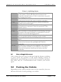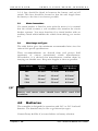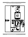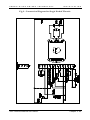
1
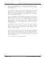
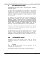
Solo Series Motor Controller OPERATION AND INSTALLATION SK74484/1 1998 Penny & Giles Drives Technology Ltd. P E N N Y + G I L E S D R I V E S T E C H N O L O G Y C O N T E N T S CONTENTS CONTENTS ....................................................... iii Chapter 1 OPERATION...................................................... 7 1.0 2.0 Introduction............................................................. 7 General...................................................................... 8 2.1 Handling .................................................................. 8 2.2 Operating Conditions............................................. 8 3.0 Controls.................................................................... 8 3.1 On/Off Switch ........................................................ 8 3.2 Status Indicator........................................................ 9 3.3 Throttle .................................................................... 9 3.3.1 Wig-wag (center off) Throttle....................9 3.3.2 Single-ended Throttle .................................9 3.4 Reverse Switch .......................................................... 9 3.5 Speed Limiting Control .......................................... 9 3.6 Slow/Fast Switch ................................................... 10 3.7 Freewheel Switch .................................................... 10 3.8 Reverse Alarm ........................................................ 10 4.0 Getting Ready to Drive.........................................10 5.0 Tips for Using Your Controller..........................11 5.1 Driving - General................................................... 11 5.2 Driving Technique................................................. 11 6.0 Precautions for Use...............................................11 6.1 Hazards .................................................................. 11 7.0 Safety Checks..........................................................12 7.1 Daily Checks........................................................... 12 7.2 Weekly Checks........................................................ 13 7.3 Servicing.................................................................. 13 8.0 Status Indication....................................................13 8.1 Status Indicator Steady.......................................... 14 8.2 Status Indicator Flashes Slowly ............................ 14 8.3 Status Indicator Flashes Rapidly........................... 14 8.4 Self-Help Guide..................................................... 14 Table 1 - Self Help Guide.............................................. 15 8.5 Slow or Sluggish Movement ................................ 15 9.0 Pushing the Vehicle..............................................15 9.1 Using Freewheel Switch ......................................... 16 9.2 Disengaging the Parking Brake............................. 16 Solo Technical Manual SK74484/1 iii C O N T E N T S P E N N Y & G I L E S D R I V E S T E C H N O L G Y 10.0 Battery Gauge.........................................................16 10.1 How To Read a Single Bulb (or LED) Battery Gauge..................................................................... 17 10.2 How To Read a TruCharge Battery Gauge...... 17 11.0 Programming.........................................................18 12.0 Controller Servicing .............................................18 Chapter 2 INSTALLATION...............................................21 1.0 Documentation ......................................................21 1.1 Solo Operation ...................................................... 21 1.2 Program Settings ................................................... 21 1.3 Other Information................................................ 22 2.0 Immobilizing the Vehicle................................... 22 2.1 Prevention of Unauthorized Use......................... 22 2.2 Charger Interlock ................................................... 22 3.0 Power Connections .............................................. 23 3.1 General ................................................................... 23 3.2 Battery Connections .............................................. 23 3.3 Motor Connections............................................... 24 3.4 Wire Gauge and Types .......................................... 24 4.0 Batteries.................................................................. 24 5.0 Motors..................................................................... 25 6.0 Control Connections............................................ 25 Fig 1 - Connection Diagram for Wig-Wag Throttle . 26 Fig 2 - Connection Diagram for Single Ended Throttle .................................................................................. 27 6.1 Throttle Potentiometer......................................... 28 6.1.1 Speed Limiting Potentiometer.................28 6.1.2 Alternative Throttle Inputs ......................28 6.2 0 Volts.................................................................... 28 6.3 On/Off Switch ...................................................... 29 6.4 Inhibit .................................................................... 29 6.5 Slow/Fast............................................................... 29 6.6 Freewheel................................................................ 29 6.7 Reverse.................................................................... 30 6.8 Batt+ (Soft Stop)................................................... 30 6.9 Reverse Alarm ........................................................ 31 6.10 Status Indicator................................................. 31 6.11 Solenoid Brake................................................... 31 7.0 Mounting................................................................ 32 7.1 Orientation............................................................. 32 7.2 Position.................................................................. 32 7.3 Cables ..................................................................... 32 8.0 Production Tests................................................... 32 8.1 Mounting............................................................... 32 iv Solo Technical Manual SK74484/1 P E N N Y + G I L E S D R I V E S T E C H N O L O G Y C O N T E N T S 8.2 Cables and Connectors.......................................... 32 8.3 Preset Settings........................................................ 33 8.4 Operational Test.................................................... 33 8.5 Test Drive............................................................... 33 9.0 Electromagnetic Compatibility (EMC) ......... 33 9.1 Emissions .............................................................. 34 9.1.1 Motor suppression.....................................34 9.1.2 Cables ..........................................................34 9.2 Immunity............................................................... 34 9.3 Electro-Static Discharge (E.S.D.).......................... 35 10.0 Battery Gauge........................................................ 35 Chapter 3 Tiller Module Installation ....................................37 1.0 2.0 Introduction........................................................... 37 Mounting................................................................ 37 2.1 Handling ................................................................ 37 2.2 Fixing...................................................................... 37 Fig 3 - Suggested fixing holes.......................................... 38 2.3 Sealing..................................................................... 38 3.0 Wiring..................................................................... 38 3.1 Soldering ................................................................ 39 3.2 Connectors ............................................................. 39 3.3 Wire Gauge............................................................ 39 4.0 Connections........................................................... 39 4.1 Connection Identification..................................... 39 Fig 4 - Connector Positions............................................. 40 4.2 Tiller Module Version - TruCharge Indicator and Diagnostics ............................................................. 40 4.3 Tiller Module Version - Momentary Switch Inputs 40 4.4 Tiller Module Version - TruCharge Indicator and Diagnostics and Momentary Switch Inputs........ 42 5.0 Electromagnetic Compatibility (EMC) .......... 42 5.1 Immunity and Emissions .................................... 42 5.2 Electro-Static Discharge (E.S.D.).......................... 43 6.0 Production Tests................................................... 43 6.1 Mounting............................................................... 43 6.2 Cables and Connections........................................ 44 6.3 Operational Tests .................................................. 44 6.3.1 TruCharge Display Function..................44 6.3.2 Switch and LED functions........................44 Solo Technical Manual SK74484/1 v P E N N Y + G I L E S D R I V E S T E C H N O L O G Y O P E R A T I O N Chapter 1 OPERATION 1.0 Introduction The relevant contents of this chapter may be included in the vehicle’s operating guide. Further copies are available from Penny & Giles in both written or disk (Word for Windows*) format. Copies should not be made without the express permission of Penny & Giles. The operation of the Solo series of controllers is simple and easy to understand. The controller incorporates state-of-the-art electronics, the result of many years of research, to provide you with ease of use and a very high level of safety. In common with other electronic equipment, correct handling and operation of the unit will ensure maximum reliability. Please read this user chapter carefully - it will help to keep the vehicle reliable and safe. *trademark gratefully acknowledged Solo Technical Manual SK74484/1 Chapter 1: 7 O P E R A T I O N P E N N Y 2.0 General 2.1 Handling & G I L E S D R I V E S T E C H N O L G Y Avoid knocking your controller, especially the connectors. Never drop the controller. When transporting, make sure that the controller is well protected. Avoid damage to cables. 2.2 Operating Conditions Your controller uses industrial-grade components throughout, ensuring reliable operation in a wide range of conditions. However, you will improve the reliability of the controller if you keep exposure to extreme conditions to a minimum. Do not expose your controller or its components to damp for prolonged periods. 3.0 Controls Depending on the specification of vehicle to which the Solo is fitted, some or all of the following controls will be used. 3.1 On/Off Switch The on/off switch applies power to the controller electronics, which in turn supply power to the motor. Do not use the on/off power switch to stop the vehicle unless there is an emergency. (If you do, you may shorten the life of the vehicle drive components). Note some vehicles may have a keyswitch in addition to the normal on/off switch, the function of the keyswitch is the same as the on/off switch. Chapter 1: 8 Solo Technical Manual SK74484/1 P E N N Y + G I L E S 3.2 D R I V E S T E C H N O L O G Y O P E R A T I O N Status Indicator Depending on the vehicle, the status indicator may be a single bulb (or LED) or a Penny & Giles TruCharge battery and diagnostics indicator. The status indicator shows you that the vehicle is switched on. It also indicates the operating status of the vehicle. Details are given in section 8.0. 3.3 Throttle The throttle controls the speed of the vehicle. The further you push the throttle, the faster the vehicle will move. When you release the throttle the brake is automatically applied. The throttle configuration may be one of two types - wig-wag (center off) or single-ended. 3.3.1 Wig-wag (center off) Throttle In this configuration, both the speed and the direction of the vehicle are controlled by the throttle. To drive forwards, push the throttle in one direction: to drive in reverse, push the throttle in the other direction. 3.3.2 Single-ended Throttle In this configuration, just the speed of the vehicle is controlled by the throttle. When the throttle is pushed depending on the position of the reverse switch (see section 3.4) - the vehicle will drive in either the forward or reverse direction. 3.4 Reverse Switch This switch will only be fitted to the vehicle if the throttle configuration is single-ended (see section 3.3.2). The switch is used to change between forward and reverse drive. 3.5 Speed Limiting Control This control sets the maximum speed of the vehicle. Turn the knob clockwise to increase the maximum speed setting or anticlockwise to decrease the maximum speed setting. Solo Technical Manual SK74484/1 Chapter 1: 9 O P E R A T I O N 3.6 P E N N Y & G I L E S D R I V E S T E C H N O L G Y Slow/Fast Switch This switch selects one of two driving modes - either ‘slow’ or ‘fast.’ You can use this switch to change the vehicle’s driving behavior in environments where that may be desirable or necessary, e.g. for working in confined areas, a slow acceleration and top speed mode can be set or if traveling long distances, high top speed and acceleration may be desirable. 3.7 Freewheel Switch This switch allows you to push the vehicle without having to mechanically disengage the parking brake. Whilst this switch is operated, the controller will not allow drive and the speed at which the vehicle can be pushed will be limited to 75% of the maximum driving speed. If you operate this switch whilst you are driving, the controller will stop the vehicle and signal a fault. 3.8 Reverse Alarm This provides an audible warning when the vehicle is being driven in the reverse direction. 4.0 Getting Ready to Drive Check that the speed limiting control is turned to a position which suits you. Operate the on/off switch. A TruCharge type status indicator will blink and turn on after half a second. A single bulb (or LED) type status indicator will turn on immediately. If the vehicle has a single-ended throttle, use the reverse switch to select the direction you want to drive and then push the throttle to control the speed. If the vehicle has a wig-wag throttle, push the throttle in the direction you want to drive. During the first half-second after the vehicle is switched on, the controller is performing important safety checks within itself and the rest of the vehicle’s electrical system. Therefore, if you push the throttle during this time, you will not be able to drive until you have returned the throttle to the rest position. This condition is Chapter 1: 10 Solo Technical Manual SK74484/1 P E N N Y + G I L E S D R I V E S T E C H N O L O G Y O P E R A T I O N indicated on a single bulb (or LED) type status indicator by a rapid flashing, or on a TruCharge type status indicator by a “rippling “ up and down of the battery gauge. If you do not push the throttle as you switch the vehicle on and the status indicator flashes rapidly, then there may be a fault. Refer to section 8.4 for details. 5.0 Tips for Using Your Controller 5.1 Driving - General Make sure that all the controls are within easy reach and are comfortable to operate. 5.2 Driving Technique The controller interprets the throttle movements and reverse switch setting (if fitted) and drives the vehicle in the correct direction at the appropriate speed. The further you push the throttle away from the rest position, the faster the vehicle will go. The intelligent speed control system minimizes the effects of slopes and different types of terrain. 6.0 Precautions for Use Note In the event of the vehicle moving in an unexpected way release the throttle. This action will stop the vehicle in any circumstances. 6.1 Hazards Do not drive the vehicle: Solo Technical Manual SK74484/1 Chapter 1: 11 O P E R A T I O N P E N N Y & G I L E S D R I V E S T E C H N O L G Y i) beyond restrictions indicated in the vehicle’s user manual. ii) in places or on surfaces where a loss of wheel grip could be hazardous, for example on wet or steep slopes. iii) if you know that the controller or other crucial components require repair. + WARNING Although the Solo is designed to be extremely reliable and each unit is rigorously tested during manufacture, the possibility of system malfunction always exists (however small the probability). Under some conditions of system malfunction the controller must (for safety reasons) stop the vehicle instantaneously. Penny & Giles accept no liability for losses of any kind arising from the unexpected stopping of the vehicle, or arising from the improper use of the vehicle or controller. 7.0 Safety Checks The electronic circuits in the Solo have been designed to be extremely safe and reliable. The on-board microcomputer carries out safety checks at up to 100 times per second. To supplement this safety monitoring you should carry out the following periodic checks. If the control system fails any of these checks, do not use the vehicle and contact your service agent. 7.1 Daily Checks Throttle: With the vehicle switched off, check that the throttle mechanism is not bent or damaged and that it returns to the rest position when you push and release it. If there is a problem do not continue with the safety checks and contact your service agent. Chapter 1: 12 Solo Technical Manual SK74484/1 P E N N Y + G I L E S 7.2 D R I V E S T E C H N O L O G Y O P E R A T I O N Weekly Checks Throttle: Put the throttle to the full speed forward position and switch the vehicle on. The vehicle should not move. To show you that you have switched the vehicle on with the throttle already pushed, a TruCharge type status indicator will “ripple” up and down, whereas a single bulb (or LED) type status indicator will flash rapidly. If the vehicle does move, contact your service agent. Parking brake: This test should be carried out on a level surface with at least one meter clear space around the vehicle: i) Switch the vehicle on. ii) Check that the status indicator remains on, or flashes slowly, after half a second. iii) Start to drive the vehicle slowly in the forwards direction until you hear the parking brake operate. The vehicle may start to move. iv) Immediately release the throttle. You must be able to hear the parking brake operate within a few seconds. v) Repeat the test in the reverse direction. Cables and connectors: Check that all connectors on the vehicle are securely mated, and ensure that all cables are free from damage. 7.3 Servicing To ensure continued satisfactory service, we suggest you have your vehicle and control system inspected by your service agent after a period of one year from commencement of service. Contact your service agent for details when the inspection is due. 8.0 Status Indication Depending on the vehicle, the status indicator may be a single bulb (or LED) or a TruCharge battery gauge and diagnostics display. Both types indicate the status of the controller. See section 10 for more details of TruCharge battery gauge. Solo Technical Manual SK74484/1 Chapter 1: 13 O P E R A T I O N P E N N Y & G I L E S D R I V E S T E C H N O L G Y Please note that a number of supposedly faulty controllers returned to Penny & Giles are subsequently found to operate correctly. This indicates that many faults are due to problems on the vehicle rather than within the controller. 8.1 Status Indicator Steady This indicates that all is well. 8.2 Status Indicator Flashes Slowly The controller is functioning correctly, but you should charge the batteries as soon as possible. 8.3 Status Indicator Flashes Rapidly The controller safety circuits have operated and the controller has been prevented from moving the vehicle. This indicates that there is a fault. Please follow this procedure: i) Switch off the vehicle. ii) Make sure that all connectors on the vehicle are mated securely. iii) Check the condition of the battery. iv) If you can’t find the problem, try using the self-help guide in section 8.4. v) Switch the vehicle on again and try to drive. If the safety circuits operate again, switch off and do not try to use the vehicle. Contact your service agent. 8.4 Self-Help Guide If a fault occurs and you have a vehicle fitted with a TruCharge display, you can find out what has happened by counting the number of bars that are flashing on the battery gauge. Here is a list of self-help actions. Try to use this list before you contact your service agent. Go to the number in the list which matches the number of flashing bars and follow the instructions. Chapter 1: 14 Solo Technical Manual SK74484/1 P E N N Y + G I L E S D R I V E S T E C H N O L O G Y O P E R A T I O N Table 1 - Self Help Guide 1 bar 2 bars 3 bars 4 bars 5 bars 6 bars 7 bars 8 bars 9 bars 10 bars 8.5 The battery needs charging or there is a bad connection to the battery. Check all connections between the controller and the battery. If the connections are good, try charging the battery. There is a bad connection to the motor. Check all connections between the motor and the controller. The motor has a short circuit to a battery connection. Contact your service agent. The freewheel switch or manual brake disengagement mechanism are operated. Check the position of the switch or lever. Not used. The controller is being inhibited from driving, this may be because the battery charger is connected or a seat (if fitted) is not in the driving position. A throttle fault is indicated. Make sure the throttle is in the rest position before switching on the vehicle. A controller fault has been indicated. Contact your service agent. There is a bad connection to the parking brake. Check all connections between the parking brake and the controller. An excessive voltage has been applied to the controller. This is usually caused by a poor battery connection. Check all connections between the battery and the controller. Slow or Sluggish Movement If the vehicle does not travel at full speed and the battery condition is good, check the position of the speed limiting control. If adjusting the speed limiting control does not remedy the problem, then there may be a non-hazardous fault. Contact your service agent. 9.0 Pushing the Vehicle Depending on the vehicle and the status of the controller, there are different methods of easily pushing your vehicle. Solo Technical Manual SK74484/1 Chapter 1: 15 O P E R A T I O N 9.1 P E N N Y & G I L E S D R I V E S T E C H N O L G Y Using Freewheel Switch If the vehicle is fitted with a freewheel switch then you can easily push the vehicle by operating this switch with the vehicle switched on. Whilst the switch is operated, the vehicle is prevented from driving and the freewheel speed is limited to 75% of the maximum driving speed. 9.2 Disengaging the Parking Brake If the vehicle does not have a freewheel switch or the controller has detected a fault, then to push the vehicle, you must mechanically disengage the parking brake. Your vehicle may be fitted with a special lever to do this. Depending on the gear ratio between the motor and the drive wheels, it may be difficult to push the vehicle. If it is, switch off the vehicle and less force will then be required. + WARNING If you have disengaged the brake and the controller has detected a fault or the vehicle is switched off, then it may be possible for the vehicle to freewheel at potentially dangerous speeds. Therefore, do not push the vehicle up or down inclines on which you cannot stop or hold the vehicle. Never sit on the vehicle when the parking brake is disengaged. Penny & Giles accept no liability for losses of any kind arising from the vehicle being moved with the parking brake disengaged. 10.0 Battery Gauge Depending on the type of vehicle, the battery gauge may be a single bulb (or LED) or a TruCharge display. How to read each type is described in the following sections. The battery gauge is included to let you know how much charge is left in your batteries. The best way for you to use the gauge is to learn how it behaves as you drive the vehicle. Like the fuel gauge in a car, it is not completely accurate, but it will help you avoid running out of “fuel”. The battery gauge works in the following way: Chapter 1: 16 Solo Technical Manual SK74484/1 P E N N Y + G I L E S D R I V E S T E C H N O L O G Y O P E R A T I O N When you switch on the controller, after half a second, the battery gauge shows an estimate of the remaining battery charge. The battery gauge gives you a more accurate reading about a minute after you start driving the vehicle. Note: When you replace worn out batteries, fit the type recommended by the vehicle manufacturer. If you use another type, the battery gauge may be inaccurate. The amount of charge in your batteries depends on a number of factors, including the way you use the vehicle, the temperature of the batteries, their age and the way they are made. These factors will affect the distance that can be traveled. All electric vehicle batteries will gradually lose their capacity as they age. The most important factor that reduces the life of your batteries is the amount of charge you take from the batteries before you recharge them. Battery life is also reduced by the number of times you charge and discharge the batteries. To make your batteries last longer, do not allow them to become completely discharged. Always recharge your batteries promptly after they are discharged. If your battery gauge reading seems to fall more quickly than usual, your batteries may be worn out. 10.1 How To Read a Single Bulb (or LED) Battery Gauge If the battery gauge is steady then you have more than 20% battery charge remaining. If the battery gauge is flashing slowly then you have less than 20% battery charge remaining and you should charge the batteries as soon as possible. 10.2 How To Read a TruCharge Battery Gauge If the battery gauge shows red, yellow and green, the batteries are charged. If the battery gauges show just red and yellow, then you should charge the batteries as soon as you can. Solo Technical Manual SK74484/1 Chapter 1: 17 O P E R A T I O N P E N N Y & G I L E S D R I V E S T E C H N O L G Y If the battery gauge shows just red, either steady or flashing slowly, then you should charge the batteries immediately. 11.0 Programming If you find that you cannot find a position of the speed limiting control that suits you, the controller can be programmed to meet your needs. The SP1 is a small hand-held unit which can be plugged into your controller to alter the program. An SP1 may be included with your vehicle. If an SP1 is not included, your vehicle distributor or service agent or vehicle manufacturer will be able to program your controller for you. If you have an SP1, read the SP1 user guide before you use it. If you re-program your controller, make sure that you observe any restrictions given in your vehicle’s user manual. Note any changes you make for future reference. The SP1 programmer should not be connected to a Solo when the vehicle batteries are being charged. The high voltages present during charging may damage the SP1 programmer. + WARNING Programming should only be conducted by competent personnel with in-depth knowledge of Penny & Giles electronic controllers. Incorrect programming could result in an unsafe set-up of a vehicle for a user. Penny & Giles accept no liability for losses of any kind if the programming of the controller is altered from factory pre-set values. 12.0 Controller Servicing All repairs and servicing must be carried out by authorized service personnel. Opening or making any unauthorized adjustments or modifications to the controller or its components will invalidate any warranty and may result in hazards to yourself or other people, and is strictly forbidden. Chapter 1: 18 Solo Technical Manual SK74484/1 P E N N Y + G I L E S + D R I V E S T E C H N O L O G Y O P E R A T I O N WARNING Penny & Giles accept no liability for losses of any kind arising from unauthorized opening, adjustment or modifications to the Solo controller. Solo Technical Manual SK74484/1 Chapter 1: 19 P E N N Y + G I L E S D R I V E S T E C H N O L O G Y I N S T A L L A T I O N Chapter 2 INSTALLATION 1.0 Documentation 1.1 Solo Operation This chapter sets out the installation conditions and procedures for correct operation of a Solo digital speed controller for use with permanent magnet motors. 1.2 Program Settings Controllers are always supplied by Penny & Giles with the manufacturer’s programmed preset settings as shown on the data sheet. The preset settings are chosen in conjunction with the vehicle manufacturer to ensure safe operation and compliance with relevant legal requirements over the whole of the operating range of the throttle, and speed limiting control. The vehicle must stop within the maximum distance specified for the country and application in which the vehicle will be used. It is recommended that the vehicle’s user handbook states that it is the responsibility of the person programming the controller to make sure that any stopping distance requirement is satisfied. If the braking rate is low, the forward and reverse maximum speed settings may need to be re-programmed. To assist the person in this task, a graph could be included in the vehicle user handbook showing the relationship between the maximum forward/reverse speed settings and the forward/reverse braking rate which is required to ensure the correct stopping distance. It may be possible to program settings which compromise the stability of the vehicle. Perform suitable tests to establish which Solo Technical Manual SK74484/1 Chapter 2: 21 I N S T A L L A T I O N P E N N Y & G I L E S D R I V E S T E C H N O L G Y programming restrictions are needed to prevent instability. State any programming restrictions in the vehicle user handbook. It is recommended that the vehicle’s user handbook states that it is the responsibility of the person programming the controller to make sure that the settings are safe and to note any programming changes that they make. + WARNING Programming should only be conducted by competent personnel with in-depth knowledge of Penny & Giles electronic controllers. Incorrect programming could result in an unsafe set-up of a vehicle. Penny & Giles accept no liability for losses of any kind if the programming of the controller is altered from factory pre-set values. Penny & Giles accept no liability for losses of any kind if the drive or stability characteristics of the vehicle are altered without prior notification and discussion with Penny & Giles. 1.3 Other Information It is recommended that a diagram be provided in the vehicle user handbook showing the user controls. In addition, you should include a brief specification of operating supply voltage range and operating temperature range. 2.0 Immobilizing the Vehicle 2.1 Prevention of Unauthorized Use Some safety requirements state that a means of preventing unauthorized use should be provided. This typically means fitting a keyswitch which can prevent the controller from being switched on. 2.2 Charger Interlock Some safety requirements state that a means of preventing the use of the vehicle while the batteries are being charged, should be provided. The Solo includes an inhibit input which can be used to provide this function. Refer to section 6.4 for details. Chapter 2: 22 Solo Technical Manual SK74484/1 P E N N Y + G I L E S D R I V E S T E C H N O L O G Y I N S T A L L A T I O N Contact Penny & Giles if you need advice. 3.0 Power Connections 3.1 General Study the data sheet for the controller to identify: i) the output current, ratings and restrictions ii) the connector pin assignments Recommendations for the cross-sectional area, ratings and materials for wiring are given in the table in section 3.4. These depend on the application. You are responsible for establishing the suitability of the particular wiring arrangement used on the vehicle. Penny & Giles can make general recommendations for wiring to Solo controllers, but Penny & Giles accepts no responsibility for the wiring arrangement used. Make sure that the connectors you use are reliable under all operating conditions and correctly wired with no short circuits. Do not use unsuitable components - it may result in poor vehicle reliability. 3.2 Battery Connections The controller incorporates sophisticated current limiting circuitry as protection for the circuits in the controller. Protection should be provided against short circuits in the battery wiring and the power loom or the extremely unlikely event of a short circuit in the controller. Place a suitable circuit breaker in series with the battery supply, and the B+ battery terminals of the controller. The rating of the circuit breaker must match the capacity of the wiring specified in section 3.4. For Solo 60 and 70A models the circuit breaker rating should not exceed a 40A maximum rating. For Solo 110A and 130A models the circuit breaker rating should not exceed 70A. These ratings refer to the MP16 series of circuit breakers manufactured by Mechanical Products Inc. Solo Technical Manual SK74484/1 Chapter 2: 23 I N S T A L L A T I O N P E N N Y & G I L E S D R I V E S T E C H N O L G Y A 1A fuse should be fitted in between the battery and on/off switch. This fuse should be located so that the wire length from the battery to the fuse is as short as possible. 3.3 Motor Connections If a circuit breaker is fitted in series with the motor, it is essential that the vehicle assumes a safe condition the moment the circuit breaker operates. You must therefore fit a circuit breaker with an auxiliary switch which inhibits the vehicle from driving, see section 6.4. 3.4 Wire Gauge and Types The table below gives the minimum recommended wire sizes for various Solo power specifications. These recommendations are derived from well proven field experience of various international vehicle manufacturers. Nevertheless, it is advised that manufacturers confirm them by carrying out suitable tests. Keep wire lengths as short as possible. + Solo Model Battery Wires Motor Wires Control Wires (inc. Brakes) 60A 2.5 mm2 2.5 mm2 0.22 mm2 70A 4.0 mm2 4.0 mm2 0.22 mm2 110A 5.0 mm2 5.0 mm2 0.22 mm2 130A 5.0 mm2 5.0 mm2 0.22 mm2 Note Battery and motor wires should have 105ºC rated PVC insulation. 4.0 Batteries The controller is designed for operation with 24 V or 36 V lead acid batteries. The batteries may be wet or gel electrolyte types. Contact Penny & Giles if you need advice on battery selection. Chapter 2: 24 Solo Technical Manual SK74484/1 P E N N Y + G I L E S 5.0 D R I V E S T E C H N O L O G Y I N S T A L L A T I O N Motors The controller is designed to be connected to a permanent magnet DC motor, fitted with a suitable gearbox and solenoid brake. In order to optimize the performance of the vehicle, the controller must be matched to the motor terminal impedance. The data sheet may define a motor compensation value (normally 70% of the total motor, cable and connector resistance). Failure to match the controller with the motor may result in poor control characteristics, in particular speed stability may be affected on gradients, for example. (See Programming and Fault Finding Technical Manual for more information). If you have any doubts about the suitability of a particular motor type or you need advice on measuring motor impedance, contact Penny & Giles. 6.0 Control Connections The control connections are via a 14 way pin header, known as P2. The mating connector is manufactured by Stocko, type MKF13274-1-0-1414. Penny & Giles can supply these parts or details of Stocko distributors world-wide. Each control connection is described hereafter. Refer also to the connection diagrams on the following pages and the controller data sheet. Solo Technical Manual SK74484/1 Chapter 2: 25 I N S T A L L A T I O N P E N N Y & G I L E S D R I V E S T E C H N O L G Y Fig 1 - Connection Diagram for Wig-Wag Throttle Chapter 2: 26 Solo Technical Manual SK74484/1 P E N N Y + G I L E S D R I V E S T E C H N O L O G Y I N S T A L L A T I O N Fig 2 - Connection Diagram for Single Ended Throttle Solo Technical Manual SK74484/1 Chapter 2: 27 I N S T A L L A T I O N 6.1 P E N N Y & G I L E S D R I V E S T E C H N O L G Y Throttle Potentiometer The throttle potentiometer is connected to P2-1, P2-2 and P2-3. Both wig-wag (center off) and single-ended throttle configuration can be used but you should ensure the controller is programmed to the correct type, refer to the SP1 Programming and Fault Finding Technical Manual and the controller data sheet. The value of the potentiometer should be between 2kΩ and 10kΩ ± 20%. If the full electrical span of the potentiometer is not used, a throttle gain can be programmed such that full speed can be achieved. Please refer to the SP1 Programming and Fault Finding Technical Manual for details. If the vehicle has a wig-wag (center off) throttle configuration it is possible, by programming, to reverse the polarity of operation of the throttle. For single ended throttles the polarity of operation of the reverse switch can be selected, refer to the SP1 Programming and Fault Finding Technical Manual. 6.1.1 Speed Limiting Potentiometer A speed limiting potentiometer may be connected between the throttle potentiometer wiper connection and P2-3 of the controller. A resistance of 25 kΩ will limit the speed to 30% of the maximum programmed speed. It is possible to use a different value potentiometer and to achieve different speed reductions, contact Penny & Giles for details. 6.1.2 Alternative Throttle Inputs Other factory programmed throttle inputs are available such as a voltage input that accepts signals in the range of 0-5V or a unipolar wig-wag input using the reverse switch to change direction. Please contact Penny & Giles for details. 6.2 0 Volts P2-4 provides the battery negative connection to the vehicle tiller. Chapter 2: 28 Solo Technical Manual SK74484/1 P E N N Y + G I L E S 6.3 D R I V E S T E C H N O L O G Y I N S T A L L A T I O N On/Off Switch P2-5 is the battery positive supply to the controller from the on/off switch. The maximum power consumption of the controller via this connection will not exceed 1A. The connection from the battery must be fused, refer to section 3.2. 6.4 Inhibit This input can be used to prevent the controller from driving the vehicle, such as when the charger is connected or when a seat (if fitted) is not in the driving position. The polarity of the input is programmable between low and high (see Programming and Fault Finding Technical Manual): low means the controller will not allow drive if P2-6 is connected to 0V. high means the controller will not allow drive if P2-6 is disconnected. 6.5 Slow/Fast This input can be used to limit the forward and reverse speeds, the forward and reverse acceleration and the forward and reverse deceleration of the vehicle. Typical uses are: to limit the vehicle’s speed and acceleration when operating in confined areas or to increase the top speed and acceleration when traveling long distances, for example. If P2-7 is connected to 0V the controller will drive using the programmed slow speeds and rates (see Programming and Fault Finding Technical Manual). 6.6 Freewheel This input can be used to release the solenoid brake so that the vehicle can be freewheeled. To release the solenoid brake P2-8 should be connected to 0V. As a safety feature, whilst this input is active the vehicle’s freewheel speed is limited to 75% of the maximum driving speed. Solo Technical Manual SK74484/1 Chapter 2: 29 I N S T A L L A T I O N P E N N Y & G I L E S D R I V E S T E C H N O L G Y Depending on the vehicle specification, the freewheel switch can be fitted in one of two positions: firstly, on the tiller (or at another convenient point) so it can be operated directly by the person wishing to push the vehicle, or, secondly, in a position such that it is operated by the solenoid brake manual disengagement mechanism. If the controller has detected a fault in either itself or elsewhere on the vehicle’s electrical system, then it is not possible to release the solenoid brake with the freewheel switch. In this instance, less force is required to push the vehicle if it is switched off. + WARNING If you have disengaged the brake and the vehicle is switched off, then it may be possible for the vehicle to freewheel at potentially dangerous speeds. Therefore, do not push the vehicle up or down inclines on which you cannot stop or hold the vehicle. Never sit on the vehicle when the parking brake is disengaged. Penny & Giles accept no liability for losses of any kind arising from the vehicle being moved with the parking brake disengaged. 6.7 Reverse If the controller is being used with a single-ended throttle configuration, this input is used to select reverse drive. The polarity of the input is programmable and can be changed using the Invert Throttle Polarity command (see Programming and Fault Finding Technical Manual). With Invert Throttle set to No, the drive will be in reverse if P2-9 is connected to 0V. With Invert Throttle set to Yes, the drive will be forwards if P2-9 is connected to 0V. 6.8 Batt+ (Soft Stop) If you require a soft-stop function, i.e. if the vehicle is switched off whilst driving it will stop with a deceleration rate equivalent to programmed value of 10 (see Programming and Fault Finding Technical Manual), then P2-10 should be connected to battery positive via the 1A fuse described in section 3.2. Chapter 2: 30 Solo Technical Manual SK74484/1 P E N N Y + G I L E S D R I V E S T E C H N O L O G Y I N S T A L L A T I O N If the soft-stop function is used you must ensure that the vehicle stops within the maximum distance specified for the country and application in which the vehicle will be used. 6.9 Reverse Alarm This output can be used to control a 24V sounder (36V with Solo36) which will operate when the vehicle is being driven in reverse. The positive terminal of the sounder should be connected, via the on/off switch, to battery positive. The negative terminal of the sounder should be connected to P2-11. The maximum current rating of the output is 50mA, you must ensure that the sounder does not draw more than this value. The controller can be programmed to give either a continuous alarm or a pulsed alarm. This can be selected by programming, see Programming and Fault Finding Technical Manual. 6.10 Status Indicator This output controls either a Penny & Giles TruCharge type status indicator or a single bulb (or LED) type status indicator. If you are using a bulb, this must be 12V with a maximum rating of 600mW: the bulb can be connected directly between P2-12 and 0V. If you are using an LED, it is connected between the same points but you must provide a series connected current limiting resistor. For details of connection to a TruCharge type status indicator, refer to the relevant data sheet. 6.11 Solenoid Brake The solenoid brake is connected between P2-13 and P2-14 and should have a maximum current rating of 2A. If the controller switches the solenoid brake and the current is less than 12mA or greater than 5A, the controller will detect a solenoid brake fault. Solo Technical Manual SK74484/1 Chapter 2: 31 I N S T A L L A T I O N P E N N Y 7.0 Mounting 7.1 Orientation & G I L E S D R I V E S T E C H N O L G Y The function of the controller is not sensitive to mounting orientation: however, to minimize the effect of water and dust, fix the controller with the metal base-plate as the underside. The controller has an IP40 dust and water resistance rating. 7.2 Position The controller must be mounted in a position where it is not exposed to water or dust, or subject to excessive shock or vibration. The controller has excellent thermal performance but, to improve this further, the base-plate may be secured against a metal part of the vehicle chassis. To provide even better thermal performance, a non-silicone thermally conductive paste or pad may be applied between the base-plate and the vehicle chassis. Contact Penny & Giles if you need further advice. 7.3 Cables The cables to the controller must be routed and secured in such a way as to prevent damage to them, for example by cutting or crushing. 8.0 Production Tests It is recommended that the following tests be performed: 8.1 Mounting Make sure that the controller is securely mounted. Do not overtighten any securing screws. 8.2 Cables and Connectors Check all cables and connectors for damage. Make sure that all connectors are securely mated. Chapter 2: 32 Solo Technical Manual SK74484/1 P E N N Y + G I L E S 8.3 D R I V E S T E C H N O L O G Y I N S T A L L A T I O N Preset Settings Make sure that the controller is using the preset settings. Refer to the chapter on programming or the Programmer User Guide for detailed instructions. Controllers are always supplied with the settings shown on the relevant data sheet. 8.4 Operational Test This test should be carried out on a level floor with at least one meter clear space around the vehicle. i) Switch on the vehicle. ii) Check that the status indicator remains on, or flashes slowly, after half a second. iii) Start to drive the vehicle slowly in the forwards direction until you hear the solenoid brake operate. The vehicle may start to move. iv) Immediately release the throttle. You must be able to hear the solenoid brake operate within a few seconds. v) Repeat the test in the reverse direction. 8.5 Test Drive Drive the vehicle and make sure that it operates correctly for all positions of the user controls. 9.0 Electromagnetic Compatibility (EMC) The Solo controller series has been tested for compliance with EC directive 89/336/EEC. The guidelines in this section will help you to make sure that your vehicle installation will easily meet the requirements of the directive. You should consider EMC and perform relevant tests as early as possible in the design phase. Solo Technical Manual SK74484/1 Chapter 2: 33 I N S T A L L A T I O N 9.1 P E N N Y & G I L E S D R I V E S T E C H N O L G Y Emissions A typical vehicle and Solo installation have been type tested and have passed the requirements of CISPR 11 and FCC CFR47 part 15. Observe the following recommendations to minimize radio frequency emissions: 9.1.1 Motor suppression Solder a suitable suppression capacitor between the brush holders of the motor, inside the motor case. Keep the lead length as short as possible. We recommend a value of 4n7F 250V AC ceramic. The maximum value you should use is 10nF. A typical type is Roderstein WY0472MCMCF0K. 9.1.2 Cables You do not need to use screened battery and motor looms, but: i) Keep the length of all wiring to a minimum. ii) Make sure the loop area of the wiring is minimized. Route the positive and negative wires to each motor together. Route the battery positive and negative wires together. Where possible, route the battery and motor looms together. iii) Secure the motor and battery looms to the vehicle chassis over as much of their length as is practical. iv) Do not use the controller connectors as junction points for the battery connections. Separate junction points away from the Solo should be provided for the other vehicle electrical functions. 9.2 Immunity The Solo controller has been stringently tested for susceptibility to electromagnetic radiation over the frequency range 26MHz to 1GHz. Follow the recommendations in section 9.1.2 to ensure maximum immunity to electromagnetic radiation. Chapter 2: 34 Solo Technical Manual SK74484/1 P E N N Y + G I L E S 9.3 D R I V E S T E C H N O L O G Y I N S T A L L A T I O N Electro-Static Discharge (E.S.D.) There are various international standards currently under development for this aspect of the system’s performance. Tests are carried out at 8kV air discharge (to non-conductive surfaces) and 6kV contact discharge (to conductive surfaces). E.S.D. produces very fast pulses of electrical energy which, if allowed to enter an electronic system, may cause disruption of operation or even permanent damage. The Solo controller incorporates extensive protection against E.S.D., however, you should take the following precautions to prevent high levels of energy entering the controller. The area where E.S.D. is most likely to enter the system is the tiller. Users who have become “charged”, for example by walking on a nylon carpet, can impart a significant discharge to the vehicle via the first point they touch. The best method of protection against such a discharge is to make all user controls and tiller enclosures nonconductive. Switch manufacturers should be able to provide appropriate advice and design rules. Where controls and enclosures are conductive, a low impedance electrical connection to the main mass of the vehicle’s metalwork should be provided. If such a connection is used, it should be kept as short as possible to minimize its electrical inductance. If there is an electrical terminal which may be vulnerable to E.S.D. but cannot be connected to the vehicle’s metalwork because of electrical isolation requirements, then an electrical connection can be provided via a varistor. The varistor should be connected between the electrical terminal and battery negative. Charger socket, battery and motor terminals do not normally require protection. If you need advice please contact Penny & Giles. 10.0 Battery Gauge Refer to Chapter 1 sections 10.1 and 10.2 for how to read the battery gauge. The battery gauge typically starts to flash slowly when the battery voltage falls below 23.3V whilst the vehicle is driving on a level Solo Technical Manual SK74484/1 Chapter 2: 35 I N S T A L L A T I O N P E N N Y & G I L E S D R I V E S T E C H N O L G Y surface. The controller can be programmed to inhibit the low battery flash, please refer to SP1 Programming and Fault Finding Technical Manual. For optimum accuracy of the battery gauge and low battery indicator, the controller should be programmed with the approximate nominal capacity of the vehicle battery. However, accuracy is not greatly affected if the programmed type and capacity do not closely match the battery. The most important factor affecting the accuracy of the battery gauge is the resistance of the cable and connections between the battery and the controller. The controller must be matched approximately to the cable resistance of the vehicle to make the battery gauge accurate, see Programming and Fault Finding Technical Manual. As a guide, 2.5 mm2 cable has a resistance of about 8 mΩ per meter; 4 mm2 cable has about 5 mΩ per meter and 6 mm2 has about 3.3 mΩ per meter. Circuit breakers and connectors usually account for about 15 mΩ. These values will be chosen at the time the controller is being specified by the vehicle manufacturer. Like the preset acceleration rates, once the values for the battery are decided, they are programmed into controllers during manufacture and should never need changing. If you need advice, contact Penny & Giles. Chapter 2: 36 Solo Technical Manual SK74484/1 P E N N Y + G I L E S D R I V E S T E C H N O L O G Y T I L L E R M O D U L E Chapter 3 Tiller Module Installation 1.0 Introduction This chapter will help you to install the range of Tiller Modules for use with the Solo series of controllers. Please read this chapter carefully as it will help to ensure the Tiller Module operates safely and reliably. It will also help you to meet the relevant safety requirements of TÜV Product Service (Germany) and ISO standards depending on the application. Study also Chapter 1: Operation and Chapter 2: Installation of this manual. There are 3 versions of the Tiller Module - TruCharge Indicator and Diagnostics, Momentary Switch Inputs and a combination of both. Depending on the version with which you are working, not all of the sections in this chapter may be applicable. Refer to the data sheet for the exact Tiller Module you have to identify which functions are present. 2.0 Mounting 2.1 Handling The Tiller Module contains electronic components which may be sensitive to static electricity. Always store the modules in the original packaging until they are ready to be used. When the modules are removed from the packaging, ensure correct anti-static precautions are taken. 2.2 Fixing The vehicle's control panel should be fitted with holes as suggested in Fig 3 shown below Solo Technical Manual SK74484/1 Chapter 3: 37 T I L L E R M O D U L E P E N N Y & G I L E S D R I V E S T E C H N O L G Y Fig 3 - Suggested fixing holes 'A' holes = 0.14" 3.3mm diameter The height of the display from the printed circuit board is 0.31" 8.0mm. Suitable spacers should be used so that the display is fixed slightly below the vehicle's control panel. Ensure that the metallic fixing hardware (nuts, washers etc.) do not touch the conductive tracks on the printed circuit board. 2.3 Sealing The module should be sealed against the ingress of water and dust by placing an adhesive waterproof overlay over the display cut-out. The overlay should contain a suitably sized transparent window and the overall dimensions should be at least 1.41" 36.0mm x 0.81" 20.5mm. 3.0 Wiring You are responsible for establishing the suitability of the particular wiring arrangement used on the vehicle. Penny & Giles can make general recommendations for wiring to Tiller Modules, but Penny & Giles accepts no responsibility for the wiring arrangement used. Chapter 3: 38 Solo Technical Manual SK74484/1 P E N N Y + G I L E S 3.1 D R I V E S T E C H N O L O G Y T I L L E R M O D U L E Soldering Wires can be soldered directly into the Tiller Module connection solder holes (see connection diagram in section 4.1), alternatively suitable solder connectors can be fitted. A good quality temperature controlled soldering iron with a suitable range of tips is required. For all soldering, to ensure long term reliability, only halide free, low residue low melting point solder containing 2% silver, should be used. No other type of solder is acceptable. All work must be carried out at an anti-static work-station with suitable operator grounding straps. The soldering equipment must also be fitted with grounded tips. 3.2 Connectors If you fit connectors to the tiller module, ensure the types you use are reliable under all operating conditions. Do not use unsuitable components as it may result in poor reliability. 3.3 Wire Gauge The minimum recommended wire size is 0.22mm2 for all connections. 4.0 Connections There are three versions of the Tiller Module - the momentary switch version, the TruCharge display version and a combination of both. Connections to each type are described in the sections 4.2 to 4.4. 4.1 Connection Identification There are two rows of solder holes for connections to the momentary switches/LEDs and the Solo controller/24V(36V)/horn. The rows are identified as CON1 and CON2 respectively. In addition, there is a solder hole to provide a static drain path for ESD purposes (see section 5.2). Fig 4 below shows the position of each connector. Solo Technical Manual SK74484/1 Chapter 3: 39 T I L L E R M O D U L E P E N N Y & G I L E S D R I V E S T E C H N O L G Y Fig 4 - Connector Positions 4.2 Tiller Module Version - TruCharge Indicator and Diagnostics For this version the following connections should be made. CON 2 Pin Connect to Function 1 Switched 24V(36V) Switched 24V(36V) 3 Solo P2-12 Status Indicator signal 7 0V or Solo P2-4 0V For connection to the ESD pin, see section 5.2. 4.3 Tiller Module Version - Momentary Switch Inputs The switches may be in the form of a membrane or conductive rubber keypad or individual pushbuttons. The input is activated by being connected to 0V (normally CON1 pin 1). Although CON1 pin 1 is 0V, it is only a low current supply and must not be used for any purpose other than tiller module input connections. Chapter 3: 40 Solo Technical Manual SK74484/1 P E N N Y + G I L E S D R I V E S T E C H N O L O G Y T I L L E R M O D U L E All LED outputs are "low side drivers", this means the LEDs must be connected between "switched 24V(36V)" (normally CON1 pin 12) and the relevant output pin. The LED current is 10mA: this is set by resistors on the tiller module, consequently, LEDs with integral series resistors should not be used. Although CON1 pin 12 is "switched 24V(36V)", it is only a low current supply and must not be used for any purpose other than the LED anode connections. The following connections should be made. CON 1 Pin Connect to Function 1 All switches Switch supply 2 On/Off switch On/Off switch input 3 Freewheel switch Freewheel switch input 4 Slow/Fast switch Slow/Fast switch input 5 Reverse switch Reverse switch input 6 Horn switch Horn switch input 7 Spare 100mA 0V supply 8 On/Off LED cathode On/Off LED output 9 Reverse LED cathode Reverse LED output 10 Slow/Fast LED cathode Slow/Fast LED output 11 Freewheel LED cathode Freewheel LED output 12 All LED anodes 24V(36V) supply for LEDs CON 2 Pin Connect to Function 1 Solo P2-5 Solo On/Off switch input 2 24V(36V) via 1A fuse 24V(36V) Solo Technical Manual SK74484/1 Chapter 3: 41 T I L L E R M O D U L E P E N N Y & G I L E S D R I V E S T E C H N O L G Y 3 Not connected Status Indicator signal 4 Solo P2-7 Solo Slow/Fast input 5 Solo P2-9 Solo Reverse input 6 Solo P2-8 Solo Freewheel input 7 Solo P2-4 Solo 0V 8 Horn -ve Horn -ve For connection to the ESD pin, see section 5.2. 4.4 Tiller Module Version - TruCharge Indicator and Diagnostics and Momentary Switch Inputs Refer to section 4.3, with the following exception. CON 2 Pin Connect to Function 3 Solo P2-12 Status Indicator signal For connection to the ESD pin, see section 5.2. 5.0 Electromagnetic Compatibility (EMC) The Solo controller series has been tested for compliance with EC directive 89/336/EEC, and the EMC requirements of prEN12184, the FDA and the FCC. The guidelines in this section will help you to make sure that your vehicle installation will easily meet the requirements of the directive. You should consider EMC and perform relevant tests as early as possible in the design phase. 5.1 Immunity and Emissions Refer to the Electromagnetic Compatibility section in Chapter 2: Installation, especially the sub-section Cables. Chapter 3: 42 Solo Technical Manual SK74484/1 P E N N Y + G I L E S 5.2 D R I V E S T E C H N O L O G Y T I L L E R M O D U L E Electro-Static Discharge (E.S.D.) In addition to this section, refer to the Electro-Static Discharge section in Chapter 2. The tiller is the most vulnerable area on the vehicle to electro-static discharges. These discharges may cause disruption of operation or even permanent damage. The tiller module incorporates extensive protection against E.S.D., however, you should take the following precautions to prevent high levels of energy entering the vehicle's electronic system. The highest degree of protection can be achieved by making the tiller enclosure, switches and other controls non-conductive. Membrane keypads in particular provide good E.S.D. protection, keypad manufacturers will be able to give appropriate design rule guidance. It should also be considered that high voltages can jump through gaps in enclosures, thereby gaining access to the electronics. Enclosures should therefore be as closed as possible. If controls or enclosures are conductive, a low impedance electrical connection to the vehicle's metalwork should be provided. If such a connection is used, it should be kept as short as possible to minimize its electrical inductance. The tiller module has a connection point, ESD: this can be used to provide an ESD drain path. The path should be via a varistor connected between the ESD pin and the vehicle's metalwork. A suitable device is manufactured by Harris, type GE-MOV V82ZA2. 6.0 Production Tests Depending on the tiller module version and the throttle configuration (wig-wag or single-ended), not all tests will be applicable. 6.1 Mounting Make sure that the tiller module is securely mounted. Do not overtighten any securing screws. Ensure that the adhesive sealing overlay is fully pressed down. Solo Technical Manual SK74484/1 Chapter 3: 43 T I L L E R M O D U L E 6.2 P E N N Y & G I L E S D R I V E S T E C H N O L G Y Cables and Connections Check all cables and connections to the tiller module for damage. Ensure there are no dry solder joints. 6.3 Operational Tests The following tests, where applicable, should be carried out on a level floor with at least one meter of clear space around the vehicle. Some of these tests can be combined with those described in chapter 2, section Production Tests. 6.3.1 TruCharge Display Function With the vehicle switched off, displace the throttle and then switch the vehicle on. The TruCharge display should "ripple" up and down. When you have observed that all the bars light then release the throttle, the display should now become steady and indicate the battery condition. 6.3.2 Switch and LED functions i) Depress and release the On/Off pushbutton. Only the status indicator should illuminate and it should be possible to drive the vehicle in the forwards direction at the programmed forward speed. ii) Depress and release the Reverse pushbutton. The Reverse LED should illuminate and it should be possible to drive the vehicle in the reverse direction at the programmed reverse speed. iii) Depress and release the Reverse pushbutton. The Reverse LED should extinguish and forward drive should again be possible. iv) Depress and release the Slow/Fast pushbutton. The Slow/Fast LED should illuminate and it should be possible to drive the vehicle in the forwards direction but only at the programmed "slow" speed. v) Depress and release the Slow/Fast pushbutton. The Slow/Fast LED should extinguish and full speed forward drive should again be possible. Chapter 3: 44 Solo Technical Manual SK74484/1 P E N N Y + G I L E S D R I V E S T E C H N O L O G Y T I L L E R M O D U L E vi) Depress and release the Freewheel pushbutton. The Freewheel LED should illuminate and it should be possible to freewheel the vehicle. vii) Depress and release the Freewheel pushbutton. The Freewheel LED should extinguish and it should not be possible to freewheel the vehicle. viii)Depress and release the Reverse, Slow/Fast and Freewheel pushbuttons, so that all the corresponding LEDs are illuminated. Depress and release the On/Off pushbutton, all LEDs should extinguish and the vehicle should be switched off. ix) Depress and release the On/Off pushbutton again. Only the status indicator should illuminate and it should be possible to drive the vehicle. x) Depress and release the On/Off pushbutton. The vehicle should now be switched off. ______________________________ Solo Technical Manual SK74484/1 Chapter 3: 45