1
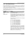
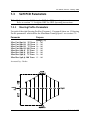
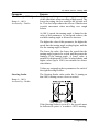
No. 60027, Issue 4. January 1998
TM
DX Servo Lighting Module (SLM)
Installation Manual
Order/Part Number for this Manual : GBK60027 issue 4
Important Notes
1.
Read this Manual carefully before installing or operating your DX control system.
2.
Due to continuous product improvement Dynamic reserves the right to update this Manual.
This Manual supersedes all previous issues which must not continue to be used.
3.
Any attempt to gain access to or in any way abuse the electronic components and
associated assemblies that make up the wheelchair control system renders the
Manufacturer’s Warranty void and the Manufacturer free from liability.
No. 60027, Issue 4. January 1998
Contents
1 Introduction . . . . . . . . . . . . . . . . . . . . . . . . . . . . . . . . . . . 1
2 Related Documentation . . . . . . . . . . . . . . . . . . . . . . . . . . . 2
3 General Description . . . . . . . . . . . . . . . . . . . . . . . . . . . . . . 3
3.1 General Features . . . . . . . . . . . . . . . . . . . . . . . . . . . . . . . . . . . . . . . . 4
3.2 Safety and Protection Features . . . . . . . . . . . . . . . . . . . . . . . . . . . . . . 4
4 Specification . . . . . . . . . . . . . . . . . . . . . . . . . . . . . . . . . . 6
4.1 Electrical Specifications . . . . . . . . . . . . . . . . . . . . . . . . . . . . . . . . . . . 6
4.2 Mechanical Specifications . . . . . . . . . . . . . . . . . . . . . . . . . . . . . . . . . 8
4.3 Environmental Specifications . . . . . . . . . . . . . . . . . . . . . . . . . . . . . . . 9
5 Installation . . . . . . . . . . . . . . . . . . . . . . . . . . . . . . . . . . . 10
5.1 Introduction . . . . . . . . . . . . . . . . . . . . . . . . . . . . . . . . . . . . . . . . . . .
5.2 Mounting . . . . . . . . . . . . . . . . . . . . . . . . . . . . . . . . . . . . . . . . . . . . .
5.3 SLM Connection with the DX System . . . . . . . . . . . . . . . . . . . . . . .
5.3.1 DXBUS Connections . . . . . . . . . . . . . . . . . . . . . . . . . . . . . . .
5.3.2 DX Module Interconnection Topology . . . . . . . . . . . . . . . . . .
5.3.3 DXBUS Length and Voltage Drop Restrictions . . . . . . . . . . .
5.4 SLM 21 Way Connector . . . . . . . . . . . . . . . . . . . . . . . . . . . . . . . . .
5.4.1 21 Way Connector Pin Definitions . . . . . . . . . . . . . . . . . . . . .
5.4.2 21 Way Connector Wires and Terminations . . . . . . . . . . . . . .
5.4.3 Power Supply from the DXBUS . . . . . . . . . . . . . . . . . . . . . . .
5.4.4 Power Supply form the Battery . . . . . . . . . . . . . . . . . . . . . . .
5.5.5 SLM Connection to Lights . . . . . . . . . . . . . . . . . . . . . . . . . . .
5.5 SLM Servo Connector . . . . . . . . . . . . . . . . . . . . . . . . . . . . . . . . . . .
5.5.1 Servo Connector Pin Definitions . . . . . . . . . . . . . . . . . . . . . .
5.5.2 Servo Connector Wires and Terminations . . . . . . . . . . . . . . .
5.5.3 SLM Connection to Servo Devices . . . . . . . . . . . . . . . . . . . .
10
10
12
12
13
15
18
18
18
19
20
21
24
24
24
25
6 Operation . . . . . . . . . . . . . . . . . . . . . . . . . . . . . . . . . . . . 26
6.1 SLM Activation . . . . . . . . . . . . . . . . . . . . . . . . . . . . . . . . . . . . . . . . 26
No. 60027, Issue 4. January 1998
7 Programming . . . . . . . . . . . . . . . . . . . . . . . . . . . . . . . . . 27
7.1 Introduction . . . . . . . . . . . . . . . . . . . . . . . . . . . . . . . . . . . . . . . . . . .
7.1.1 Adding an SLM to the DX System . . . . . . . . . . . . . . . . . . . . .
7.2 DX Remote PCD Parameters . . . . . . . . . . . . . . . . . . . . . . . . . . . . . .
7.2.1 Lighting Parameters . . . . . . . . . . . . . . . . . . . . . . . . . . . . . . . .
7.2.2 Drive Program Parameters . . . . . . . . . . . . . . . . . . . . . . . . . . .
7.3 SLM PCD Parameters . . . . . . . . . . . . . . . . . . . . . . . . . . . . . . . . . . .
7.3.1 Steering Profile Parameters . . . . . . . . . . . . . . . . . . . . . . . . . .
7.3.2 Other PCD Parameters . . . . . . . . . . . . . . . . . . . . . . . . . . . . . .
7.4 Using the PCD . . . . . . . . . . . . . . . . . . . . . . . . . . . . . . . . . . . . . . . .
7.5 Calibrating the SLM using the HHP . . . . . . . . . . . . . . . . . . . . . . . . .
7.5.1 Initial Operation . . . . . . . . . . . . . . . . . . . . . . . . . . . . . . . . . . .
7.5.2 Calibrating Parameters . . . . . . . . . . . . . . . . . . . . . . . . . . . . . .
27
28
29
29
30
32
32
35
43
44
44
46
8 Diagnostics . . . . . . . . . . . . . . . . . . . . . . . . . . . . . . . . . . 48
8.1 Troubleshooting . . . . . . . . . . . . . . . . . . . . . . . . . . . . . . . . . . . . . . . .
8.2 Flash Codes . . . . . . . . . . . . . . . . . . . . . . . . . . . . . . . . . . . . . . . . . . .
8.3 PCD Diagnostics . . . . . . . . . . . . . . . . . . . . . . . . . . . . . . . . . . . . . . .
8.3.1 Status Report . . . . . . . . . . . . . . . . . . . . . . . . . . . . . . . . . . . . .
8.3.2 Fault History . . . . . . . . . . . . . . . . . . . . . . . . . . . . . . . . . . . . .
48
48
53
53
54
9 Maintenance . . . . . . . . . . . . . . . . . . . . . . . . . . . . . . . . . . 57
10 Safety and Misuse Warnings . . . . . . . . . . . . . . . . . . . . . . . 58
11 Warranty . . . . . . . . . . . . . . . . . . . . . . . . . . . . . . . . . . . . 59
12 Sales and Service Information . . . . . . . . . . . . . . . . . . . . . 60
No. 60027, Issue 4. January 1998
1
Introduction
The Servo Steering and Lighting Module (SLM) controls the steering and lighting
for servo steered power wheelchairs. It is part of a DX System also comprising a
DX Power Module and a DX Remote as a minimum system.
Side Lights
Left
Indicator
Lights
Right
Indicator
Lights
Drive
o p tio n al
Motor 2
D X B US
DX
R emote
S LM
S e rvo
Mo to r
DX BU S
DX -PM -(S )
24 V
Battery
Drive
Motor 1
Example of Minimum DX System with the SLM
The servo wheelchair has one motor for steering, and either one or two motors to
provide the driving power of the wheelchair. Both functions are controlled by the
DX Remote. If two drive motors are used then a dual channel DX Power Module
(DX-PM) is required. If only one drive motor is used then a single channel DX
Power Module (DX-PM-S) is required.
The lighting consists of side lights and turn indicators. The indicators can be flashed
together to provide a hazard warning. The lights are also controlled by the DX
Remote.
The SLM has two standard DXBUS connectors so that it may be connected to the
DX System.
This manual and others listed in Section 2 must be read and understood. For more
information contact Dynamic Controls Ltd or an agent as listed in section 12.
1 Introduction
1
No. 60027, Issue 4. January 1998
2
Related Documentation
A DX based wheelchair control system may comprise between two and sixteen DX
compatible modules depending on the application. Each DX compatible module has
its own Installation Manual which describes the installation requirements of that
particular module.
This manual describes the installation of the SLM only and must be read in
conjunction with the :
!
Relevant DX Remote Installation Manual
!
DX Power Module (PM) Installation Manual
!
DX Hand Held Programmer (HHP) Manual
!
DX Programming Configuration Diagnostic (PCD) Manual
!
Installation Manuals for all other DX modules to be used in your system.
2
2 Related Documentation
No. 60027, Issue 4. January 1998
3
General Description
The SLM is designed to enable the DX System to run on a servo steered power
wheelchair, with lights. The wheelchair will have: a servo motor, a position sense
potentiometer, a steering release microswitch, one or two drive motors with integral
park brakes, a 24 V battery supply, and optional lights.
There are two versions of the SLM. The SLM utilises 24 V lights while the SLMTÜV utilises 12 V lights and has an internal voltage regulator.
The DX system will comprise of a minimum of a DX Remote, a DX Power Module,
a SLM and may also have up to 13 other DX modules.
The DXBUS is used to control and monitor all DX Modules. The DX Power
Module has two identical DXBUS connectors and is connected in a chain type
arrangement with the SLM. The SLM can be powered from an independent 24 V
power supply, but low power steering requirements can be powered from the
DXBUS 24 V supply. The lighting can also be supplied from: the DXBUS, an
internal or external regulated 12 V supply, or from the 24 V wheelchair battery. See
section 5.4.3 and 5.4.4.
In a servo system the speed and direction data from a DX Remote is passed to the
SLM rather than directly to the DX Power Module. The SLM processes the speed
data and then sends it directly to the DX Power Module. The direction signal is
processed by the SLM and applied to the servo steering motor. A position sense
potentiometer tells the SLM the steering position.
A microswitch is attached to the steering clutch so that when the clutch is released
for manual wheelchair manoeuvring, the system is inhibited and will not drive.
When the clutch is restored, the system must be turned off then on again to drive.
The DX System allows up to five preset Drive Programs to be selected, depending
on the type of remote. Each Drive Program contains an associated Steering Program
that defines the maximum steering lock available at different speeds, for safe
driving. The SLM controls the steering lock to conform to the Steering Program,
and also controls the speed output so that the speed can not exceed that allowable
for a particular lock.
The SLM can control a full lighting system of side lights (front and rear) and
indicator lights (left and right). The activation of the lights is via the DX Remote.
The SLM can be used with a two channel (60 A per channel) DX Power Module
(DX-PM) or a single channel 120 A DX Power Module (DX-PM-S). If only one
drive motor is used in the system then the DX-PM-S will be used.
3 General Description
3
No. 60027, Issue 4. January 1998
3.1
General Features
The SLM has the following general features:
!
Servo output capable of supplying 5 A continuous and 30 A peak to a 24 V
servo actuator.
!
Fully DXBUS compatible.
!
Two identical DXBUS sockets for Daisy Chain connection to the DX System.
!
Powered by a 24 V wheelchair battery via the DXBUS connection, or directly
from the battery for high current applications.
!
Fully programmable for optimum driving performance.
!
Lighting outputs are TÜV approved when fitted with approved regulated power
supply (SLM-TÜV).
!
Electromagnetically compatible:
- not susceptible to high levels of RFI
- emitting low levels of RFI
- protected against high levels of ESD.
!
Compact case for mounting under the wheelchair seat.
3.2
Safety and Protection Features
The SLM has the following safety and protection features:
!
Motor current limit and current limit timeout set to prevent overheating of
motors.
!
Thermal protection to reduce current limit.
!
Short circuit protection of all inputs and outputs except between motor and
battery negative while driving.
!
Open circuit motor detection when not driving.
!
Driving is inhibited if steering clutch is disengaged.
!
Over voltage, under voltage and reverse battery protected.
4
3 General Description
No. 60027, Issue 4. January 1998
!
Detection of broken steering position feedback potentiometer connections or
short circuit of the potentiometers` terminals.
!
Driving inhibit if Steering Module is not connected and responding.
!
Compliance with ISO 7176 requirements.
!
Controlled power down in event of DXBUS disconnection or communication
failure.
!
Hazard lights can be operated by an external switch.
!
Hazard lights will operate automatically if communication with the DX Remote
is lost while turned on.
!
Indicator flash rate will double if a rear indicator bulb has failed.
!
Side lights will come on if battery charger is over-charging the batteries or
during regenerative braking if the battery cannot absorb the regenerated power.
3 General Description
5
No. 60027, Issue 4. January 1998
4
Specifications
4.1 Electrical Specifications
Power Supply Input
Symbol
Parameter
Conditions
Min
Nom Max
VBAT
IQ
IO
IDXBUS
Battery voltage
Quiescent Current
Operating Current
DXBUS Current
18.0 24.0
No servo load
+ servo load
RMS Continuous to entire system
Units
32.0
150
250
12
V
mA
mA
A
Nom Max
Units
Servo Motor + / - Output
Symbol
Parameter
Conditions
SM+
IAV
Output Voltage
Continuous
Average Current
Peak Output Current
When not in current limit VBAT-1.2V
Over programmable
5
time period
For up to 5 sec.
Î
Min
VBAT
V
A
30
A
Servo Pot Input / Output
Symbol
Parameter
SP+
Pot Supply +
Open circuit
Output Voltage
Pot Supply Output Voltage
SP+ Output impedance
SP- Output Impedance
Acceptable Pot
Impedance
SPZSP+
ZSPZSP
6
Conditions
Min
Nom Max
4.5
5.0
0.0
950
4K
5.5
Units
V
V
1 K 1050 Ohms
10
Ohms
10 K 12 K Ohms
4 Specifications
No. 60027, Issue 4. January 1998
Steering Clutch Switch
Symbol
Parameter
Conditions
VLO
VHI
Low level switch voltage Microswitch closed
High level switch voltage Microswitch open
Min
0
3.5
Nom Max
0.5
5.0
Units
V
V
Lighting Specification
Symbol Parameter
Conditions
Min Nom Max Units
Turn Indicator Outputs (each output)
VTIO
VTIO
ITIO
Output Voltage
Output Voltage
Continuous Output
Current
13.5 V regulator fitted
13.1 13.5 13.9
13.5 V regulator not fitted VBAT-1 VBAT-0.1 VBAT
2.3
2.5
V
V
A
Sidelight (Head / Tail Light) Output
VSLO
VSLO
ISLO
Output Voltage
Output Voltage
Continuous Output
13.5 V regulator fitted
13.1 13.5 13.9
13.5 V regulator not fitted VBAT-1 VBAT-0.1 VBAT
2.3
2.5
V
V
A
13.5 V Regulated Power Supply (SLM TÜV only)
VREG
IMAX
Output voltage
Maximum output
current
Voltage In 18-32V
Max. total lighting
load (Note 1)
13.1
7.5
13.6 14.0
9.0 11.0
V
A
Note 1 The nominal lighting current corresponds to the sidelights and hazard
flashing. The supply will current limit at 9 A (nominal) to blow fuses. It is not
intended to be used at this level for any extended period of time.
4 Specifications
7
No. 60027, Issue 4. January 1998
4.2
Mechanical Specifications
Size:
210 * 123 * 38 mm
Weight:
0.530 Kg
Mounting:
M5 screws four places, or placed in tray
Case material:
Aluminium sheet, powder coat finish
Case sealing:
Tamper proof, IP54 if mounted as per mounting instructions
SLM Configuration
8
4 Specifications
No. 60027, Issue 4. January 1998
4.3
Environmental Specifications
Parameter
Minimum
Operating ambient temperature range
Storage temperature range
Operating and storage humidity
Maximum
-25
-25
0
50
70
90
Units
C
EC
%RH
Electromagnetic Compatibility
Specification (EMC)
prEN12184 : 1997 (pending)
Durability
Vibration Specification
ISO7176 part 14
120 minutes @ 4 g’s random vibration without
damage.
4 Specifications
9
No. 60027, Issue 4. January 1998
5
Installation
5.1
Introduction
Installing a SLM requires the following steps:
1. Mounting the SLM
Refer Section 5.2
2. SLM Connection with the DX system
Refer Section 5.3
3. SLM 21 Way Connector
Refer Section 5.4
4. SLM Servo Connector
Refer Section 5.5
5. Programming the SLM related parameters
Refer Section 7.0
5.2
Mounting
Optimum mounting orientation
Fit the SLM with the top label facing up.
Unacceptable Mounting Orientation
Do not mount with connectors facing up.
Do not mount with the top label facing down.
Other orientations are acceptable.
10
5 Installation
No. 60027, Issue 4. January 1998
Securing the SLM
The SLM can be mounted using the four mounting holes and mounting screws
provided, or placed in a suitable tray. Do not use screws which protrude into the
SLM case by more than 12 mm.
The SLM must be mounted in a position which offers the maximum protection from
water and mechanical abuse. Since there are no user accessible controls on the
SLM, it can be mounted in a position which is inaccessible to the user e.g. under the
seat.
Note For ease of diagnosis, it is recommended that the SLM be mounted where
the SLM Status LED can be seen without having to remove covers.
5 Installation
11
No. 60027, Issue 4. January 1998
5.3
SLM Connection with the DX System
5.3.1
DXBUS Connections
2 x DXBUS Connectors
Note If only one DXBUS connector is used on the SLM and the remaining
connector is accessible to the wheelchair user, a dummy DXBUS plug should be
fitted to the unused connector. This will comply with ISO 7176.
A dummy DXBUS plug can be made from:
DXBUS Connector Boot
DXBUS Connector Housing
Part/Order Number GCN 0789
Part/Order Number GCN 0792
Like all other DX Modules the SLM is connected to the DX system using the
DXBUS. Cables are available in the following standard lengths:
DXBUS CABLE, Straight,
DXBUS CABLE, Straight,
DXBUS CABLE, Straight,
DXBUS CABLE, Straight,
DXBUS CABLE, Straight,
0.1 M
0.3 M
0.5 M
1.0 M
1.5 M
Part/Order Number GSM 63001
Part/Order Number GSM 63003
Part/Order Number GSM 63005
Part/Order Number GSM 63010
Part/Order Number GSM 63015
DXBUS cables are also available with ferrites fitted.
Note The order and positioning of the SLM within the DX system is important and
must be based on the rules discussed in section 5.3.2 and 5.3.3.
12
5 Installation
No. 60027, Issue 4. January 1998
5.3.2
DX Module Interconnection Topology Options
The battery and DX Power Module combination are always considered the heart of
a DX system. Other DX Modules can be arranged in several ways:
Splitter Box
DX
Power
Module
DX
M o d u le
DX
M o d u le
Battery
24V
Splitter Box
Note :
DX
M o d u le
D X B U S C a b le
Star DXBUS Topology
DX
R e mo t e
B a tte r y
24V
DX
Power
Mo d u le
DX
M o d u le
DX
M o d u le
DX
M o d u le
DX
M o d u le
DX
M o d u le
In-line DXBUS Topology
5 Installation
13
No. 60027, Issue 4. January 1998
Splitter Box
DX
Pow er
M o d u le
B a tte r y
24V
DX
M o d u le
DX
M o d u le
DX
M o d u le
DX
M o d u le
DX
M o d u le
DX
M o d u le
Mixed DXBUS Topology
DX modules normally have one or two DXBUS sockets for system
interconnections. Smaller DX modules may have a permanently mounted cable
terminated in a DXBUS plug, rather than DX sockets.
The star and mixed topologies both require the use of one or more DX Splitter
Boxes. A Splitter Box is a separate panel of four DXBUS sockets that may be
purchased from Dynamic or a Dealer.
The DX Splitter Box Part/Order Number is: DX-SKT-X4.
For lowest cost and simplicity the In-line topology is generally preferred, provided
the DXBUS length and voltage drop requirements described below can be met.
Warning If the SLM is between the PM and the Battery Charger:
1. Have as few as possible DXBUS cables between the SLM and the PM.
2. The DXBUS cables between the SLM and the PM must not total more
than 1 metre.
This will avoid unintended interaction between the SLM and the Battery Charger.
14
5 Installation
No. 60027, Issue 4. January 1998
5.3.3
DXBUS Length and Voltage Drop Restrictions
Due to signal distortion that increases with increasing DXBUS length, the total
length of all DXBUS cables must not exceed 15 metres in any topology.
Two of the DXBUS's four cores (DXB+ and DXB-) are used to supply power to the
modules and to the loads connected to them. A Positive Temperature Coefficient
(PTC) device in the Power Module limits the total DXBUS current to 12 A, to
protect the DXBUS wiring and connectors. The topology and cable lengths used
may reduce the DXBUS's upper limit to below 12 A.
For correct DX System operation the voltage drop on the DXBUS's DXB- wire due
to return currents, must not exceed 1.0 V between any two modules within the DX
System. Use a topology and module placement that reduces this voltage drop as low
as reasonably possible.
Voltage drops occur along the DXBUS due to the return of current back to the
battery through the small but finite resistance of the DXBUS cable and connectors.
A DXBUS connector can be modelled as:
Rct
Rca
Rct
Rca
DXBUS Cable Model
Rct = contact resistance = 5 mOhm
Rca = cable resistance = 12 mOhm / metre
5 Installation
15
No. 60027, Issue 4. January 1998
Example:
Consider a Power Module connected to an SLM via five other DX Modules using
1 metre cables.
DX Power Module
I
DX
Module
DX
Module
DX
DX
Module Module
DX
Module
SLM
Battery
24V
Servo Motor
Example of DX Module interconnection
The total resistance of the 0 V return path, between the Power Module and SLM is:
6 X (2 * Rct + Rca) = 132 mOhms
This means that the maximum load that the SLM can drive and not exceed the
1.0 V drop requirement is 1 / 0.132 = 8 A.
If, for example, the servo motor and lighting that the SLM is required to drive has
a peak current of 10 A the interconnection order of the DX modules will have to be
changed to place the SLM closer to the Power Module.
The above example illustrates a fundamental rule of DX Module interconnection
All DX Modules that connect to high current loads (e.g. actuators / motors and
lights) must be connected as close to the Power Module as possible.
The above example is simplified and does not include current to other DX Modules.
The DXBUS maximum current rating of 12 A is for the entire DX System.
Operation of the SLM at its maximum rating of 30 A peak current is not possible
from the DXBUS supply. To supply greater than the 12 A DXBUS current, see
section 5.4.4.
16
5 Installation
No. 60027, Issue 4. January 1998
This favours topologies such as:
Ba tt e ry
24V
DX
Po w e r
M o d u le
H
H
H
L
L
Low Current Modules
Furthest away from
Power Module
H ig h C u r r e n t Mo d u l e s
N e a re s t Po w e r Mo d u le
Rationalised In-line Topology
B a tt er y
24V
H
L
L
H
L
L
DX
Po w e r
M od u le
Two way star Topology
B atte ry
2 4V
H
Splitter Box
DX
Po w e r
M od u le
H
H
H
L
L
Multi Star Topology
5 Installation
17
No. 60027, Issue 4. January 1998
5.4
SLM 21 Way Connector
5.4.1
21 Way Connector Pin Definitions
1
2
8
9
15
16
3
4
5
6
Pin
7
14
Function
1
2
DXBUS Side Lights -
3
Left Indicator -
4
5
Right Indicator 13.5 V
6
Hazard In
7
8
Hazard Out
Battery -
9
Steering Power +
14
15
Battery - (spare)
DXBUS +
16
Lighting +
Note : Other pins unused.
5.4.2
21 Way Connector Wires and Terminations
To build a matching connector
To build a matching connector to fit to the 21 way connector, the parts are :
DX 21W Plug Housing
DX 21W Boot
DX Positronics Contact, FC114N2 (Lge)
DX Positronics Contact, FC116N2 (Med)
DX Positronics Contact, FC120N2 (Sml)
Part/Order Number GCN 0796
Part/Order Number GCN 0795
Part/Order Number GCN 0793
Part/Order Number GCN 0797
Part/Order Number GCN 0794
The DX Positronics Contacts are crimp terminals.
18
5 Installation
No. 60027, Issue 4. January 1998
Wire Sizes
The minimum wire sizes that must be used are :
Function
DXBUS Side Lights Left Indicator Right Indicator 13.5 V
Hazard In
Hazard Out
Battery Steering Power +
DXBUS +
Lighting +
5.4.3
Wire Size (minimum)
Terminal Part
1.0 mm²
0.5 mm²
0.5 mm²
0.5 mm²
1.0 mm²
0.5 mm²
0.5 mm²
1.0 mm² motors < 10 A
2.0 mm² motors > 10 A
1.0 mm² motors < 10 A
2.0 mm² motors > 10 A
1.0 mm²
1.0 mm²
Positronic
Industries Ltd
FC116N2
FC120N2
FC120N2
FC120N2
FC116N2
FC120N2
FC120N2
FC116N2
FC114N2
FC116N2
FC114N2
FC116N2
FC116N2
Power Supply from the DXBUS
The DXBUS is suitable for powering low speed servo motors and non TÜV
lighting, where the DX System current requirement is less than the 12 A DXBUS
rating. The DXBUS is not suitable for powering the SLM if TÜV compliance is
required.
To power the lighting and servo motor from the DXBUS, links must be inserted to
short the DXBUS - pin to the Battery - pin, and the DXBUS + pin to the Steering
Power and Lighting + pins.
5 Installation
19
No. 60027, Issue 4. January 1998
5.4.4
Power Supply from the Battery
When the servo motor and lighting require more current than the 12 A DXBUS
current rating has available, the SLM must be powered directly from the battery.
Both battery negative terminals on the SLM must be used to achieve TÜV
compliance.
Note Heavy lines denote 3 mm² or heavier wire. All other wires from the 21 way
connector as specified in section 5.4.2.
20
5 Installation
No. 60027, Issue 4. January 1998
Thermal circuit breakers must be installed in the battery wiring to protect the
batteries, wiring loom and SLM from external short circuits. If the two batteries are
permanently wired together (single battery box), the best position for this circuit
breaker is between the two batteries. If the batteries are individually plugged
together (separate battery boxes), each battery requires a circuit breaker. Separate
lighting and driving circuit breakers are used, so that a fault which causes a circuit
breaker to operate, will not disable both lighting and driving.
Battery - has two connections to the SLM. This is to ensure that a break in one
battery will not disable driving or lights.
Battery Type
The DX System is designed to perform optimally with either Lead-Acid or Gel Cell
deep cycle batteries. Consult Dynamic Controls for other battery types. It is
recommended that two 12 V batteries with capacity greater than 20 A hours be
used.
5.4.5
SLM Connection to Lights
There are three lighting outputs : Pin 2 Side Lights Pin 3 Left Indicators Pin 4 Right Indicators -
The Side Light Output
This output is used to power head and tail lights. Multiple bulbs can be connected
to the output in parallel, as shown in the following diagram. The output is active
pull-down when the light is turned on.
The Left and Right Indicator Outputs
These outputs are also active pull-down when the light is turned on. Again, multiple
bulbs can be connected to each output.
5 Installation
21
No. 60027, Issue 4. January 1998
Power Source
Wiring of the lights is dependant on the source of the power. When the regulated
13.5 V Power Supply is fitted (SLM-TÜV), the lights are wired to Pin 5. When not
fitted (SLM), the lights are wired to Pin 16.
For convenience, the standard SLM which has no such regulator, has Pin 5
connected to Pin 16 internally. This allows the lights to be wired to Pin 5.
Pin 16 supplies the power to operate the lighting control circuits and also the
13.5 V regulator if fitted.
Example of Lighting Wiring
22
5 Installation
No. 60027, Issue 4. January 1998
SLM-TÜV Lighting Connections
The three lighting outputs are:
Pin 2 Side Lights
Pin 3 Left Indicators
Pin 4 Right Indicators
Note : The SLM-TÜV is designed to blow fuses leading to shorted lamps. When
wired as shown, a blown fuse will not prevent other lamps on the same circuit from
continuing to operate.
Right
Side
Lights
Left
Side
Lights
Left
Indicator
Right
Indicator
6W
6W
10W
10W
10W
10W
21W
21W
2A
2A
2A
2A
Rear
2A
Side
Left
Right
13.5V
2A
Front
SLM
Connector
Hazard Switch
An external Hazard Switch can be
connected between Pins 6 and 7. When
this switch is closed, both indicator
outputs will flash synchronously at a rate
of 75 flashes per minute.
5 Installation
23
No. 60027, Issue 4. January 1998
5.5
SLM Servo Connector
5.5.1
Servo Connector Pin Definitions
3
2
1
6
5
4
front view
5.5.2
Pin
1
2
3
4
5
6
Function
Motor Common Ground
Position Sense Pot +
Motor +
Clutch Switch
Position Sense Wiper
Servo Connector Wires and Terminations
To build a matching connector
To build a matching connector to fit the Servo Connector, the parts are :
AMP Mate-N-Lok Connector Housing
AMP Part Number 1-480-704-0
(DCL Part Number GCN 0201)
Amp Universal Mate-N-Lok Contact
For 0.5 mm² wires
AMP Part Number 350690-1
(DCL Part Number GCN 0202)
Amp Universal Mate-N-Lok Contact
For 1.0 and 2.0 mm² wires *
AMP Part Number 350547
(Solid pin)
AMP Part Number 350705
(Split pin)
24
5 Installation
No. 60027, Issue 4. January 1998
Wire Sizes
The minimum wire sizes that must be used are :
Function
Wire Size (minimum)
Terminal Part
Motor -
1.0 mm² motors < 10 A
2.0 mm² motors > 10 A
Common Ground
0.5 mm²
Position Sense Pot +
0.5 mm²
Motor +
1.0 mm² motors < 10 A
2.0 mm² motors > 10 A
Clutch Switch
0.5 mm²
Position Sense Pot Wiper 0.5 mm²
*
*
AMP 350690
AMP 350690
*
*
AMP 350690
AMP 350690
* AMP Split pin or Solid pin part numbers given above.
5.5.3
SLM Connection to Servo Devices
When the steering wheels are centred, there should be equal resistance between the
Position Sense Pot wiper and each end of the pot. Small differences can be
overcome during calibration (refer to the Programming section).
To SLM Servo Connector
AMP Mate - N - Lok Connector
The motor wiring should be
such that when pin 4 is positive
with respect to pin 1, the servo
motor turns the pot so that the
pot wiper (pin 6) is driven
towards pot + (pin 3).
(AMP P/N 1-480-704-0)
4
2
5
6
3
Clutch
1
Servo
steering
motor
5 Installation
5 - 10 K Ω
potposition
sense
25
No. 60027, Issue 4. January 1998
6
Operation
6.1
SLM Activation
The SLM is operated by a DX Remote. Each DX Remote has different facilities and
not all support a full lighting system. The operation of the lighting is therefore very
dependent on what remote it is used with.
Please consult the User Manual for the DX Remote used in your SLM application.
26
6 Operation
No. 60027, Issue 4. January 1998
7
Programming
Warning
Incorrect or inappropriate programming of a DX System may put the wheelchair
into a dangerous state.
Dynamic Controls accept no responsibility or liability for accidents caused by
incorrect programming.
This chapter must be read and understood before attempting to program a DX
System containing an SLM.
7.1
Introduction
The driving performance of an SLM is dependant on its programming. An SLM can
be adjusted for a particular application and the driving performance defined to suit
the requirements of an individual.
The SLM is programmed at the time of manufacture with factory settings defined
by the wheelchair manufacturer (OEM) and Dynamic Controls Ltd. Some
parameters may be modified later using the HHP, for individual user requirements.
If more than one type of wheelchair is to be used by the customer, each wheelchair
type may have its own set of optimum settings.
Non module specific programming of a DX System is contained in the PM and DX
Remote Installation Manuals. A servo steered DX System with one drive motor,
uses a single channel DX-PM-S, a two drive motor system a DX-PM, which are
programmed appropriately at the time of manufacture : see the PM Installation
Manual.
The DX Remote can access as many as five drive programs which are treated
differently in a servo steered DX System. The settings contained in these programs
must be selected with reference to this SLM Installation Manual. There are also
three lighting parameters that must be set up in the DX Remote program if lighting
functions are required.
7 Programming
27
No. 60027, Issue 4. January 1998
7.1.1
Adding an SLM to the DX System
Any DX Remote can be used to control either conventional or servo steered DX
Systems. While it is possible to edit a conventional wheelchair program to a servo
application using the PCD, the complexity of the operation makes it inadvisable.
When changing to a servo steered system, select a servo wheelchair program and
modify to suit the requirements of the wheelchair type.
Similarly, to change a DX Remote from a servo to a conventional application, select
a conventional wheelchair program to edit as required and download to the DX
Remote.
28
7 Programming
No. 60027, Issue 4. January 1998
7.2
DX Remote PCD Parameters
Note Refer to section 7.4 ‘Using the PCD’ for PCD operating instruction.
Parameters related to the SLM contained in the DX Remote program fall into two
categories : lighting parameters and Drive Program parameters.
7.2.1
Lighting Parameters
The lighting parameters must be enabled so that lights will operate (SLM-TÜV).
Parameter
Purpose
Side Lights Enable
If set to ‘yes’, sidelights (front and rear) are enabled.
State yes / no
Accessed by : OEM
If set to ‘no’, there will be no response to a DX
Remote sidelight button being pressed (other than a
beep for some varieties of remotes).
Indicators Enable
As for the Side Lights Enable parameter
State yes / no
Accessed by: OEM
Hazard Enable
As for the Side Lights Enable parameter
State yes / no
Accessed by: OEM
7 Programming
29
No. 60027, Issue 4. January 1998
7.2.2
Drive Program Parameters
The DX System supports up to five Drive Programs. The Drive Programs are
defined in the DX Remote programming as factory settings specified by the
customer. The Drive Programs govern the driving performance of the wheelchair as
suitable for different environmental conditions.
The DX Remote Drive Programs are covered in the relevant DX Remote Installation
Manual. Three Drive Program Parameters are however treated differently in the
servo steered DX System.
Parameter
Maximum Turning
Speed
Purpose
The maximum speed available when the joystick is
fully deflected left or right.
Range 10 - 100 %
Accessed : DCL
The value assigned to Maximum Turning Speed is not
a single performance setting, but a pointer to select one
of eight Steering Programs : see section 7.3.1. The
Steering Programs are defined by the PCD in the SLM
wheelchair program.
The Maximum Turning Speed value selects a Steering
Program as follows :
10 - 49 % selects Steering Program 1
50 - 54 % selects Steering Program 2
55 - 59 % selects Steering Program 3
60 - 64 % selects Steering Program 4
65 - 69 % selects Steering Program 5
70 - 74 % selects Steering Program 6
75 - 79 % selects Steering Program 7
80 - 100 % selects Steering Program 8
The Steering Programs values can be conventionally
assigned so that Steering Program 1 causes the slowest
possible turning, progressing up to Steering Program 8
causes the fastest possible turning. If this
recommendation is followed, Maximum Turning Speed
appears to have the same affect in a servo steering
application as in a conventional system.
30
7 Programming
No. 60027, Issue 4. January 1998
7 Programming
31
No. 60027, Issue 4. January 1998
Parameter
Turning Acceleration
Range 10 - 70 %
Accessed by : DCL
Purpose
The rate of response when the joystick is deflected left
or right from neutral. A value of 10% gives slow
response, 70% gives fast response.
This defines the rate at which the SLM attempts to
respond to a large increase in steering lock. A small
increase in lock demand is approached at the maximum
possible acceleration. The lock demand at which this
parameter is used is set by the PCD in the SLM
wheelchair program by the Turning Accel Pt
parameter.
Turning Deceleration
Range 15 - 100 %
Accessed by : DCL
The rate of response when the joystick is deflected left
or right towards neutral. A value of 15% gives slow
response, 100% gives fast response.
This defines the rate at which the SLM attempts to
respond to a large decrease in steering lock. A small
decrease in lock demand is approached at the
maximum possible deceleration. The lock demand at
which this parameter is used is set by the PCD in the
SLM wheelchair program, also by the Turning Accel Pt
parameter.
Note The Turning Deceleration value is normally set as high or higher than the
Turning Acceleration value. An inadequate Turning Deceleration value can result
in an unsafe wheelchair condition.
7 Programming
32
5 Installation
No. 60027, Issue 4. January 1998
7.3
SLM PCD Parameters
Note Refer to section 7.4 Using the PCD for PCD operating instruction.
Refer to section 7.5 Using the HHP for HHP operating instructions.
7.3.1
Steering Profile Parameters
For each of the eight Steering Profiles (Program 1 - Program 8) there are 12 Steering
Profile parameters which define the Maximum Turning Speed : see section 7.2.
Parameter
Purpose
Range (%)
Max Fwd Spd @ 25 Turn
Max Fwd Spd @ 50 Turn
Max Fwd Spd @ 75 Turn
Max Fwd Spd @ 100 Turn
Max Rev Spd @ 25 Turn
Max Rev Spd @ 50 Turn
Max Rev Spd @ 75 Turn
Max Rev Spd @ 100 Turn
35 - 100
25 - 100
20 - 100
15 - 100
35 - 100
25 - 100
20 - 100
15 - 100
Accessed by : Dealer
5 Installation
33
No. 60027, Issue 4. January 1998
Parameter
Purpose
The first eight parameters define the maximum
forward and reverse speeds for four non-zero turning
positions : 25, 50, 75 and 100% turning. The greater
+the turning %, the less the assigned speed value
should be. It is assumed that a safe speed is the same
for left and right turning.
Wheelchairs with a lower maximum speed should
have higher Max Fwd Spd and Max Rev Spd
settings than faster wheelchairs as they are less risk
of tipping over. It is reasonable, for slower
wheelchairs, to set Max Fwd and Rev Spd @ 25%
(and possibly 50%) Turn to 100%.
As a general guide: speed at 25% turn should be
twice that at 100% turn; speed at 50% turn should
be 1.4 times that at 100% turn; and speed at 75%
turn should be 1.2 times that at 100% turn.
Values are assigned to these eight parameters for
each of the eight Steering Profiles.
The maximum forward and reverse speeds at zero
turning are defined by the standard Drive Program
parameters.
Turning Accel Pt
Range 0 - 100 %
Accessed by : Dealer
Defines the minimum error between the turning
demand and the actual turning angle at which the
Turning Acceleration and Turning Deceleration
parameters apply.
Max Servo Motor Spd
The maximum servo motor speed possible.
Range 10 - 100 %
Accessed by : Dealer
Values are assigned to this parameters for each of
the eight Steering Profiles.
7 Programming
34
No. 60027, Issue 4. January 1998
Parameter
Max Turn @ 100% Speed
Range 0 - 100 %
Accessed by : Dealer
Purpose
The purpose of this parameter is to give finer control
of the wheelchair when travelling at high speed. The
lower the setting, the less sensitive the joystick will
be. This also helps reduce the effects of inadvertent
joystick movement when travelling over rough
terrain.
At 100 % speed, the turning angle is limited to the
value of this parameter. As the speed reduces, the
available turning angle is allowed to increase.
The higher the value of this parameter, the higher the
speed that the turning angle scaling begins, and the
less the turning angle is limited.
The lower the value, the lower the speed that the
turning angle begins to be scaled, and the greater the
limiting of the turning angle. A lower value is
suitable for high speed (10 km / h) wheelchairs, and
higher values (up to 100%) are suitable for slower
wheelchairs.
Values are assigned to these parameters for each of
the eight Steering Profiles.
Steering Scalar
The Steering Scalar value scales the % turning so
that 100% turning occurs closer to neutral.
Range 0 - 100 %
Accessed by : Dealer
If the Steering Scalar is set to 0%, the joystick must
be deflected to point ‘a’ to achieve 100 % turning.
7 Programming
35
No. 60027, Issue 4. January 1998
Parameter
Purpose
A Steering Scalar value of 100% will double the %
turning so that 100% turning will occur at point ‘b’,
mid way between neutral and point ‘a’. Further
deflection towards point ‘a’ will not give any
increase in turning.
A higher value is more suitable for diamond shape
joystick restrictor plates, a lower value for square,
round or octagonal restrictor plates.
The purpose of this adjustment is to allow full lock
to be achieved with some wheelchair speed,
therefore higher values are more suitable for slower
wheelchairs and lower values for high speed
wheelchairs.
7.3.2
Other PCD Parameters
Parameter
Purpose
Enable Lighting
If set to ‘en’, lighting functions are enabled.
State en / dis
Accessed by : OEM
If set to ‘dis’, there will be no response to a DX
Remote lighting button being pressed (other than a
beep for some varieties of remotes).
Current Limit
The current limit for the servo motor. The SLM will
ensure that no more than the stated current will go
through the servo motor.
Range 4 - 40 amperes
Accessed by : OEM
PM Dir Scalar
Range 0 - 100 %
Accessed by : OEM
7 Programming
36
For use with two drive motor DX Systems and
compensates for different drive wheel spacing.
Determine how much one motor increases and the
other decreases in speed when the wheelchair is
turning. If this parameter is set to 100 %, the inner
drive wheel will have zero speed when turning.
This value has no effect when a DX-PM-S is used.
No. 60027, Issue 4. January 1998
Parameter
Purpose
Squared Dir Output
Set to ‘on’ if the Power Module (DX-PM) drives a
front motor and a rear motor.
Set to ‘off’ if the Power Module (DX-PM) drives a
left motor and a right motor.
State on / off
Accessed by : Dealer / OEM
A single channel Power Module (DX PM-S) does
not use this parameter.
Speed Scalar
The Speed Scalar value scales the speed so that
100% speed occurs closer to neutral.
Range 0 - 100 %
Accessed by : Dealer
If the Speed Scalar is set to 0%, the joystick must be
deflected to point ‘c’ to achieve 100 % forward or
reverse speed.
A Speed Scalar value of 100% will double the speed
demand so that 100% speed will occur at point ‘d’,
mid way between neutral and point ‘c’.
The purpose of this adjustment is to allow full speed
to be achieved with some turning deflection.
Veer (right +)
Range ± 127
Accessed by : Dealer / User
HHP Calibrated
The adjustment of the neutral steering position so
that the wheelchair does not veer when the joystick
is pushed directly forwards or backwards.
The veer adjustment is to correct small offsets in the
straight-ahead position of the position feedback
potentiometer. Large offsets should be corrected
mechanically first. See section 5.5.3.
7 Programming
37
No. 60027, Issue 4. January 1998
Parameter
Purpose
Physical Pot Limits
Actual Lock Limits
Lock Margin
Lock Margin
Pot Voltage Tolerance
Right Lock
Left Lock
Min Pot End V
0V
0%
100%
SP+
Max Pot End V
Position
Sense
Pot
Left Lock
Range 5 - 95 %
Accessed by : Dealer / User
HHP calibrated
Right Lock
Range 5 - 95 %
Accessed by : Dealer / User
HHP calibrated
The ratio of the Position Sense Pot Wiper voltage to
the full pot voltage when the steering wheels are
moved as far left as is mechanically possible.
A physical limitation calibrated using the HHP - refer
to section 7.5.
The ratio of the Position Sense Pot Wiper voltage to
the full pot voltage when the steering wheels are
moved as far right as is mechanically possible.
A physical limitation calibrated using the HHP - refer
to section 7.5.
Note: The Left and Right Lock parameters must not both be above nor both be
below 50%. Typically one will be around 25% and the other around 75%, so that
the total will be around 100%.
7 Programming
38
No. 60027, Issue 4. January 1998
Parameter
Purpose
Pot Voltage Tol
Specifies the tolerance of the Left Lock and Right
Lock, in % of total pot travel. If the pot position
falls within this tolerance then a Steering Fault
(SLM Flash Code 3) is displayed by the SLM (refer
to Diagnostics section 8).
Range 0 - 50 %
Accessed by : DCL
This value is typically set to half the Lock Margin
Value.
Lock Margin
Range 0 - 50 %
Accessed by : DCL
The lock margin voltage ratio, added or subtracted to
Left Lock and Right physical Locks. It should be
set so that the SLM will target the positions of
maximum steering deflection when the joystick is
deflected fully left or right.
It must be set higher than the Pot Voltage Tol
parameter to avoid an error when the wheelchair is in
full left or right lock.
Warning: Setting Max Pot End V too high or Min Pot End V too low may
prevent some position sense potentiometer faults being detected.
Max Pot End V
Range 3200 - 5000 mV
(3.2 - 5V)
Accessed by : DCL
Min Pot End V
Range 3000 - 4900 mV
(3 - 4.9 V)
Accessed by : DCL
Parameter
The maximum allowable voltage at the + end of
the position sense potentiometer. If the voltage
exceeds this value, a Steering Fault (SLM Flash
Code 3) is displayed by the SLM.
A suggested value is 4.75V for a 10K ohm
potentiometer.
(Refer to Diagnostics section 8)
The minimum allowable voltage at the + end of the
position sense potentiometer. If the voltage is less
than this value, a Steering Fault (SLM Flash
Code 3) is displayed by the SLM.
A suggested value is 4.3V for a 10K ohm
potentiometer.
(Refer to Diagnostics section 8)
Purpose
10 Safety and Miisuse Warnings
39
No. 60027, Issue 4. January 1998
Motor Speed
Range 20 - 5,100 ms
(0.02 - 5.1 sec.)
Accessed by : Dealer / User
HHP calibrated
The time taken for the servo motor to travel the full
range from left lock to right lock, and visa
versa.
This is calibrated using the HHP.
Motor Damping Factor
The speed of response of the servo motor.
Range 0 - 100 %
Accessed by : DCL
For slow motors this value should be low and for
fast motors the damping should be high.
Warning An unsuitably high or low value can
make the wheelchair unstable.
Restrict Fwd Spd 25 %
Restrict Fwd Spd 50 %
Restrict Fwd Spd 75 %
Restrict Fwd Spd 100 %
Restrict Rev Spd 25 %
Restrict Rev Spd 50 %
Restrict Rev Spd 75 %
Restrict Rev Spd 100 %
Accessed by : Dealer / User
HHP calibrated
Range (%)
60 - 100
40 - 100
20 - 100
0 - 100
60 - 100
40 - 100
20 - 100
0 - 100
The maximum forward and reverse speeds for four
non-zero lock positions : 25, 50, 75 and 100 %
turning lock.
The physical restrictor plate fitted to the DX
Remote is calibrated with these parameters, using
the HHP.
If the DX Remote is replaced, these parameters
must be recalibrated.
Parameter
7 Programming
40
Plate parameters are grouped and calibrated in one
operation of the HHP.
Purpose
No. 60027, Issue 4. January 1998
Stall Time
Range 5 - 50 seconds
Accessed by : DCL
Stall Timeout
State yes / no
Accessed by : DCL
The stall timeout delay. If the current limit is
exceeded for more than this time a Stall Timeout
Fault (SLM Flash Code 11) will be displayed by
the SLM (refer to Diagnostics section 8).
If set to ‘yes’, driving is disabled after Stall Time if
in current limit.
A Stall Timeout Fault (Flash Code 11) is displayed
by the SLM (refer to Diagnostics section 8).
I²T
If set to ‘on’, motor I²T is enabled.
State on / off
Accessed by : DCL / OEM
I²T parameters define the thermal characteristics of
the motors used in wheelchair.
The OEM must provide sample motors or detailed
motor specifications to Dynamic Controls Ltd.
Dynamic will provide recommended setting to
ensure correct motor protection against
overheating.
I²T Threshold
I²T parameter, see above.
Range 10 - 90 %
Accessed by : DCL / OEM
Motor Time Scale
I²T parameter, see above.
Range 10 - 200
Accessed by : DCL / OEM
Max Motor Temp
Range 70 - 200 EC
Accessed by : DCL / OEM
The maximum motor temperature used for I²T
protection of the motor.
I²T parameter, see above.
7 Programming
41
No. 60027, Issue 4. January 1998
Parameter
Purpose
High Voltage Roll/b Start
Above this battery voltage, the wheelchair speed
will be progressively reduced. The purpose is to
reduce excessive battery voltage when the
wheelchair is driven down a slope.
Range 24 V - 33 V
Accessed by : DCL
When the battery voltage exceeds this voltage, the
SLM will automatically turn on the side lights to
prevent the battery being over charged.
Note A value of 29 V or greater is recommended
to avoid the side lights coming on when the battery
is charging.
High Voltage Roll/b End
Range 28 V - 33 V
Accessed by : DCL
Above this battery voltage, no driving speed will
be available.
This value should be greater than the High Voltage
Roll/b Start value.
Waggle Time
The time taken to perform (and thereby the
severity of) the Waggle Test. Refer to the Waggle
Range 20 - 5100 ms (5.1 sec.) Test parameter.
Accessed by : DCL
Waggle Test
State : on / off
Accessed by : DCL
Straighten at Start
State : yes / no
Accessed by : DCL
7 Programming
42
If set to ‘on’, a Waggle Test is performed when the
DX System is turned on,. This test involves the
steering wheels turning one way, then the other,
before returning to the original position. If the
Straighten at Start parameter is set to ‘yes’, then
the wheels will return to the centre position.
If set to ‘yes’, the steering wheels will straighten
when the DX System is turned on.
No. 60027, Issue 4. January 1998
Parameter
Purpose
Steer Err Reduce
Every 20 msec. the voltage at the Position Sense
Pot is checked and any error added to a
Cumulative steering Error value. Prior to this
addition, the Cumulative Steering Error is scaled
by the Steer Err Reduce value.
Range 50 - 95 %
Accessed by : DCL
The higher the Steer Err Reduce value, the more
quickly the Cumulative Steering Error is likely to
accumulate. If it goes above a preset threshold
(refer to the Steer Err Threshold parameter) a
Steering Error (SLM Flash Code 3) is produced
(refer to Diagnostics section 8).
Steer Err Threshold
If the Cumulative Steering Error reaches the Steer
Err Threshold, a Steering Error (SLM Flash
Range : 10 - 100 %
Code 3) is displayed by the SLM (refer to Accessed
by : DCL Diagnostics section 8).
Steer Clutch Active
State : high / low
Accessed by : OEM
Set to ‘low’ if clutch input is active low, i.e. input
is low if steering disengaged.
Set to ‘high’ if clutch input is active high.
7 Programming
43
No. 60027, Issue 4. January 1998
7.4
Using the PCD
Programmable parameters relating to the SLM are contained in the DX Remote
(UCM Remote) and the SLM programs. These programs can be modified using
the PCD (Programming Configuration Diagnostic) tool.
To view and / or edit these parameters:
1. Enter the PCD's Main Menu screen as described in the PCD Manual.
2. Select the "Edit Wheelchair Library" menu option.
3. Select either "Edit Standard Wheelchair Program" or "Edit Custom
Wheelchair Program" where appropriate.
4. Select the chair program that you wish to view or edit.
5. Select the "Edit Module Parameters" menu option.
6. Select "SLM" or "UCM Remote".
7. Scroll through the list of parameters. See sections 7.2 and 7.3 for the list of
parameters that require programming and their functions. Adjust parameters
as required.
8. Press 'ENTER' to accept the changes or 'ESC' to exit without saving. Select
"Write Program to Library" option and press 'ENTER'. These values will now
be part of the Standard Wheelchair Program for this type of wheelchair and
be automatically downloaded to the DX Remote and the SLM when using the
"Program Wheelchair" option.
7 Programming
44
No. 60027, Issue 4. January 1998
7.5
Calibrating the SLM using the HHP
There are twelve SLM parameters that must be calibrated to the individual
wheelchair system using the HHP. These parameters are all described in section
7.3.
The first four parameters calibrated by the HHP are approached sequentially. The
eight Restrictor Plate parameters are grouped and calibrated in one operation of
the HHP.
7.5.1
Initial Operation
1. Plug HHP into the Programmer Socket on the DX Remote and turn the DX
System on. The initial screen appears for two seconds.
Dynamic DX
Programmer
VERSION 1.10
2. Then the main menu screen reads :
* * MAIN MENU * *
View or edit?
Program : 1 ?
NEXT
YES
3. Press 'NEXT' until the Technician Mode screen appears :
* * MAIN MENU * *
Technician Mode
disabled. Enable ?
NEXT
YES
7 Programming
45
No. 60027, Issue 4. January 1998
4.
Press 'YES' and a screen will appear to enter the three digit password.
Technician Mode
Enter Password
000
D1
D2
EXIT
D3
Press the D1, D2 and D3 buttons to cycle each digit through to the correct
password. When the password reads correctly, press the 'EXIT' button.
5.
The screen now reads :
* * MAIN MENU * *
Technician Mode
enabled. Disable ?
NEXT
YES
Step four toggles this screen between Technician Mode Enabled to
Technician Mode Disabled.
6.
Press 'NEXT" until the screen reads :
ì
* * MAIN MENU * *
View or edit Servo
Steering Module ?
NEXT
YES
Press 'YES'.
7.
Press 'YES'. The display reads:
VIEW/EDIT SERVO MOD
Veer compensation
Right 39
EXIT
NEXT
LEFT RIGHT
7 Programming
46
No. 60027, Issue 4. January 1998
7.5.2
Calibrating Parameters
Pressing ‘EXIT’ at any point during the calibration procedure will return you to
screen
.
ì
1.
Calibrate the Veer Compensation (Veer (right +)) Parameter.
í
VIEW/EDIT SERVO MOD
Veer compensation
Right 39
EXIT
NEXT
LEFT RIGHT
Press 'LEFT' and ‘RIGHT’ to adjust the value. The range is ± 127.
Selecting the correct value will require experimentation. When calibration
is completed test drive the wheelchair. Select a Veer Compensation value
so that the wheelchair does not veer when the joystick is pushed directly
forwards or backwards. If the wheelchair veers right, press ‘LEFT’; if the
wheelchair veers left, press ‘RIGHT’.
If a large compensation value is required, the mechanical position of the
position sense potentiometer may require adjustment - see section 5.3.3.
2.
Calibrate the Right Lock Parameter. The range is 0 - 100 %.
VIEW/EDIT SERVO MOD
Right Lock
84%
EXIT
NEXT
UP
DOWN
Press 'UP' and ‘DOWN’ until steering wheels are moved as far right as is
mechanically possible. Press the HHP buttons slowly and firmly, and
pause between each press.
Press ‘NEXT’.
3.
Calibrate the Left Lock Parameter as per the Right Lock Parameter.
7 Programming
47
No. 60027, Issue 4. January 1998
4.
Calibrate the Motor Speed Parameter.
VIEW/EDIT SERVO MOD
Max motor speed
calibration
EXIT
NEXT
START
Press 'START'. The steering wheels move to left and right extremes, then
return to centre.
Press ‘NEXT’.
This calibration should be performed with the normal weight on the chair
i.e. while sitting on the chair.
5.
Calibrate the Restrictor Plate (Restrict Fwd/Rev Spd) Parameters.
This procedure calibrates the speed for four forward and four reverse
turning positions.
VIEW/EDIT SERVO MOD
Restrictor plate
calibration
EXIT
NEXT
START
Press 'START'.
VIEW/EDIT SERVO MOD
Trace joystick
outline
EXIT
SAVE
Move the joystick around the outer physical extremities of the restrictor
plate. Ensure that all corners are pressed into.
Press ‘SAVE’ to return to the previous screen.
6.
í or if calibration has been completed,
press 'EXIT' to return to
ì , then ‘NEXT’.
Note ‘NEXT’ must be pressed in screen
ì so that the calibration
Press ‘NEXT’ to return to
settings are saved to both the SLM and the DX Remote.
Unplug the HHP and turn off the DX System.
7 Programming
48
No. 60027, Issue 4. January 1998
8 Diagnostics
SLM diagnostics can be examined from two platforms : from the Flash Codes
displayed by the SLM (and DX Remote), and from the PCD (Programming
Configuration Diagnostic) tool. The PCD can provide more detailed information
about the nature of the fault.
8.1
Troubleshooting
! The SLM may not run at all, or operate in an unexpected way, if the
programmable parameters are not set up correctly. Using the PCD, examine
all the parameters detailed in section 7 to ensure they are correctly set up for
your application.
! The side lights may come on while the battery charger is plugged in. This
may be caused by:
1. The Battery Charger may be overcharging or charging at too high a rate.
2. The SLM is between the Battery Charger and the PM and the DXBUS
cables are too long. See section 5.3.2.
3. The PCD parameter High Voltage Roll/b Start may be set too low.
! Chair starts to veer, but no flash codes are reported.
1. Mechanical slipping of the body or shaft of the steering position sense
potentiometer.
2. Mechanical slipping of the steering assembly.
These may not be severe enough to generate a stepping feedback fault but
will require mechanical adjustment.
8.2 Flash Codes
Any fault condition on the DX system will cause the DX Remote's System Status
LED (generally the Power On indicator) to flash. Flashing occurs in bursts of
flashes separated by a two second pause. The number of flashes in each burst is
referred to as the Flash Code and indicates the nature of the fault.
8 Diagnostics
49
No. 60027, Issue 4. January 1998
The SLM also detects faults, which it then conveys to the DX Remote. Flash
codes are always displayed on the DX System Status LED but in most cases the
SLM will also display a flash code on its Status LED. Some SLM flash codes are
just a reflection of the flash code on the DX Remote, while others give additional
information. Refer to the table following.
Faults that affect the safety of the wheelchair will cause the wheelchair to stop,
while less critical ones will be indicated but allow the wheelchair to continue
driving. Some faults will automatically clear when the fault condition is removed
(non-latched) while others are latched and must be cleared by turning the DX
System off and then on again.
If the suggested action does not remove the fault, contact a Dynamic Sales and
Service Centre (refer to section 12).
DX System
Status LED
Flash Code
1
SLM Status Likely Cause of Fault and Possible Action
LED Flash
Code
1
Module Fault
Cause: Connections between DX Modules may be
faulty, or there may be an internal fault in
the SLM.
Action < Check DXBUS connections and replace
where necessary.
< Replace SLM.
< Consult an approved Dynamic Service
Agent
2
Motor Fault
Cause: A servo motor fault has been detected.
Action: < Check wiring to motor.
< Check servo motor for a short or open
circuit.
8 Diagnostics
50
No. 60027, Issue 4. January 1998
DX System
Status LED
Flash Code
2
SLM Status Likely Cause of Fault and Possible Action
LED Flash
Code
3
Steering Fault
Cause: The Position Sense Pot is faulty or cannot
track the requested steering position.
Action: < Check the Pot Shaft is not slipping, or the
Pot. Body turning.
< Check the Pot For short and open circuits
between pins.
< Ensure that the clutch is engaged and not
slipping.
< Ensure that there is no excessive load on
the steering system.
< Check the servo motor connector and
wiring.
Note: If this problem only occurs when large
steering movements are requested, the SLM`s motor
speed parameter may need to be recalibrated using
an HHP.
2
4
Lighting Fault
Cause: 1. A fault is detected in the lighting circuits
or the internal regulator (if fitted).
2. Indicator lights are flashing faster than
Action: < Check the lighting circuitry for shorts and
open circuits.
< Check side and indicator bulbs.
5
Clutch Released
Cause: The clutch switch is or has been in the
released position.
Action: < Re-engage the clutch if necessary and turn
the DX System off then on.
< Check the servo motor connector and
wiring.
< Check the operation of the clutch switch.
8 Diagnostics
51
No. 60027, Issue 4. January 1998
DX System
Status LED
Flash Code
7
SLM Status Likely Cause of Fault and Possible Action
LED Flash
Code
7
Low Battery Voltage Fault
Cause: The battery voltage has fallen below 17 V.
Action: < Check battery connections and terminals.
< Check fuses have not blown or circuit
breakers tripped.
< Replace battery if worn out.
9
9
CANL Fault
Cause: 1.An invalid voltage has been detected on
the DXBUS CANL line.
2. Communication is not possible using the
CANL wire.
Action: < Check the continuity of the DXBUS
cable.
< Check for shorts between DXBUS pins.
An open or short circuit on another DX
module can cause this fault.
8 Diagnostics
52
No. 60027, Issue 4. January 1998
DX System
Status LED
Flash Code
10
SLM Status Likely Cause of Fault and Possible Action
LED Flash
Code
10
CANH Fault
Cause: 1. An invalid voltage has been detected on
the DXBUS CANH line.
2. Communication is not possible using the
CANH wire.
3. Hazard lights were turned on when the
DX System was turned on.
Action: < Check the continuity of the DXBUS cable.
< Check for shorts between DXBUS pins.
An open or short circuit on another DX
module can cause this fault.
< If the Hazard Lights were already
switched on when the DX System was
turned on, Flash Code 10 and Limp Mode
(slow driving) may result.
To clear this fault, turn the Hazard Lights
off, then turn the DX System off then on
again.
11
11
Stall Timeout Fault
Cause: The servo motor current has been at or close
to current limit for longer than the Stall
Timeout parameter value.
Action: < Turn the DX System off then on again.
8 Diagnostics
53
No. 60027, Issue 4. January 1998
8.3 PCD Diagnostics
The PCD (Programming Configuration Diagnostic) tool can be used to provide
diagnostics for the SLM.
To view diagnostics :
1. Enter the PCD's Main Menu screen as described in the PCD Manual.
2. Select ‘Diagnose Faults’.
The PCD displays the following menu :
Status Report
Fault History
Erase Fault History
Print Fault History
Terminal Emulation
8.3.1 Status Report
To view the Status Report :
1. Perform steps 1. and 2. above.
2. Select ‘Status Report’.
3. From the ‘Modules Attached’ menu, select ‘SLM’.
8 Diagnostics
54
No. 60027, Issue 4. January 1998
8.3.2 Fault History
To view the Fault History :
1. Enter the PCD's Main Menu screen as described in the PCD Manual.
2. Select ‘Diagnose Faults’.
3. Select ‘Fault History’.
4. From the ‘Modules Attached’ menu, select ‘SLM’.
Below are listed the Fault History codes and probable causes of these faults. If
the suggested action does not remove the fault, contact a Dynamic Sales and
Service Centre (refer to section 12).
Message
Possible Cause and Action
CPU / General
Fault
Cause : Internal Fault
Action: < Replace SLM.
< Consult an approved Dynamic Service Agent.
Hall / Overtemp /
ADC Fault
Cause: Internal Fault
Action: < Replace SLM.
< Consult an approved Dynamic Service Agent.
Relay / Precharge
Fault
Cause : 1. Short between a motor terminal and Battery +.
2. Internal Fault
Action: < Repair fault if found.
< Consult an approved Dynamic Service Agent.
Port Feedback
Fault
Cause: Internal Fault
Action: < Consult an approved Dynamic Service Agent.
Motor Summation
Fault
Cause : 1. External motor terminal short circuit.
2. A short circuit between a motor terminal
and: a battery terminal, a Position
Sense Pot terminal, or a clutch switch
terminal.
Action :
< Check for the above and repair if
necessary.
8 Diagnostics
55
No. 60027, Issue 4. January 1998
Message
Fault and Possible Cause
Steering Fault
Cause : 1. Position Sense Pot may have mechanical
fault such as the pot turning or the shaft
slipping.
2. Clutch may be slipping.
3. The steering may be excessively loaded.
4. Incorrect motor speed calibration.
Action : < Check the Position Sense Pot for mechanical
failure.
< Ensure that the clutch is properly engaged
< Ensure that there is nothing impeding the
movement of the steering wheels.
< Recalibrate SLM using an HHP.
Pot Wiper Voltage Cause : 1. The Position Sense Pot Wiper may be open
circuit.
2. The Position Sense Pot Wiper may be
shorted to: a battery terminal, an end
terminal on the pot, the clutch switch, or a
motor terminal.
3. Faulty Pot.
Action : < Check for the above and repair if necessary.
< Check voltage on Position Sense Pot + end
terminal.
Pot Res Fault
Cause : 1. A Position Sense Pot end terminal may be
open circuit.
2. Any Position Sense Pot terminal may be
shorted to: a battery terminal, another
terminal on the pot, the clutch switch, or a
motor terminal.
3. Faulty Pot.
4. Incorrect setting of Pot End Min. Voltage
Or
Pot End Max. Voltage
Action : < Check for the above and repair if necessary.
< Check voltage on Position Sense Pot + end
terminal.
< Correct programming and reprogram chair.
Motor O/C Fault
Cause : Servo motor or wiring may be open circuit.
Action : < Check motor and wiring.
8 Diagnostics
56
No. 60027, Issue 4. January 1998
Message
Fault and Possible Cause
Stall Timeout
Fault
Cause : The servo motor current has been at or close to
current limit for longer than the Stall Timeout
parameter value.
Action : < Turn the DX System off then on again. Allow
to cool down if necessary.
< Check that steering wheels can turn freely.
Battery Low
Cause : The battery voltage is less than 17 V
Action : < Recharge or replace battery.
Battery High
Cause : The battery voltage is greater than 32 V
Action : < Check that battery charger is operating
correctly.
< May be caused by continuous braking down a
hill at too higher speed. The problem will
occur when batteries are fully charged, fully
discharged or worn out.
Lighting SMPS
Fault
Cause : 1. A short circuit between the 13.4 V regulated
supply (if fitted) and battery + or -.
2. There is no power supplied to the lighting.
Action : < Check all lighting circuitry.
< Check wiring as per section 5.4.3 and 5.4.4.
Head Light Fault
Cause : The circuitry for the Side Lights (front and rear)
is faulty.
Action : < Check for an open circuit, or a short circuit
from the Side Lights to battery + or -.
< Check for blown headlight bulbs.
Left Indicator
Fault
Cause : The circuitry for the Left Indicator Light is
faulty.
Action : < Check for an open circuit, or a short circuit
from the Left Indicator Light to battery + or < Check for blown left indicator bulbs.
Right Indicator
Fault
Cause : The circuitry for the Right Indicator Light is
faulty.
Action : < Check for an open circuit, or a short circuit
from the Right Indicator Light to battery +
or -.
< Check for blown right indicator bulbs.
10 Safety and Miisuse
8 Diagnostics
Warnings
57
No. 60027, Issue 4. January 1998
9 Maintenance
1. The DX System should be regularly checked for integrity. Loose, damaged or
corroded connectors or terminals, or damaged cabling should be replaced.
2. All switchable functions on the DX System should be regularly tested to
ensure they function correctly.
3. All DX system components should be kept free of dust, dirt and liquids. If
necessary wipe with a cloth dampened with warm water or alcohol. Do not
use solvents or abrasive cleaners.
4. Where any doubt exists, consult your nearest Service Centre or Agent.
5. There are no user-serviceable parts in any DX System component - do not
attempt to open any case.
Warning If any DX component is damaged in any way, or if internal damage
may have occurred (for example by being dropped), have it checked by qualified
personnel before operating
9 Maintenance
58
No. 60027, Issue 4. January 1998
10
Safety and Misuse Warnings
All warnings throughout this Installation Manual must be read and understood. If
in doubt ask for advice.
This DX component must not be used other than in the manner described in this
Installation Manual.
The completed installation must be thoroughly checked, and all programmable
options must be correctly adjusted for safe operation prior to use.
Pass on to user:
A warning must be conveyed to the wheelchair user that the controller could
cause the chair to come to a sudden stop. In situations where this may affect
the safety of the user, this will require the fitting and wearing of a seat belt.
The DX control system is fully programmable to optimise performance and
safety. Do not operate the wheelchair unless you have full control. Ensure
that the chair is correctly programmed for your needs and environment and
ask your dealer to adjust if necessary. Always choose a Drive Program that
you feel safe with and that is compatible with your environment.
Do not operate the DX System if it behaves erratically, or shows abnormal
response heating, smoke or arcing. Turn the system off, disconnect the
battery or open the battery overload switch, and consult your Service Agent.
Do not operate the DX System if the battery is nearly flat as a dangerous
situation may result due to loss of power in an inopportune place.
Ensure the controller is turned off when not in use.
No connector pins should be touched, as contamination or damage due to
electrostatic discharge may result. Dummy sockets in unused DXBUS
connectors should be left in place unless a new module is added to the
system.
Report any malfunctions immediately to your Service Agent.
10 Safety and Miisuse Warnings
59
No. 60027, Issue 4. January 1998
11
Warranty
All equipment supplied by Dynamic Controls Ltd is warranted by the company to
be free from faulty materials or workmanship. If any defect is found within 15
months (three months allowable for shelf life) of the date of purchase, the
company will repair the equipment, or at its discretion, replace the equipment
without charge for materials and labour.
The Warranty is subject to the provisions that the equipment:
! Has been correctly installed.
! Has been used solely in accordance with this manual.
! Has been properly connected to a suitable power supply in accordance with
this manual.
! Has not been subjected to misuse or accident, or been modified or repaired
by any person other than someone authorised by Dynamic Controls Ltd.
! Has been used solely for the driving of electrically powered wheelchairs in
accordance with the wheelchair manufacturer's recommendations.
11 Warranty
60
No. 60027, Issue 4. January 1998
12
Sales and Service Information
For Sales and Service advice, or in case of any difficulty, please contact:
Head Office
Dynamic Controls Limited
Print Place
Christchurch
New Zealand
Telephone: Int. 64 3 338 0016
Fax:
Int. 64 3 338 3283
Australia
Electronic Mobile Service (EMS)
46 Berripa Close
North Ryde, Sydney
NSW Australia 2113
Telephone: Int. 61 2 887 2824
24 hours:
Int. 61 2 963 1778
Fax:
Int. 61 2 887 2114
North America
Rosstron Inc
1521 W. 259th St
Harbor City, CA 90710
USA
Telephone: Int. 1 310 539 6293
Fax:
Int. 1 310 539 4078
Europe
Controls Dynamic Ltd
Lisle Avenue
Kidderminster
DY11 7DL
United Kingdom
Telephone
Fax:
Int. 44 1562 820 055
Int. 44 1562 742 720
Note : The controller should be clearly labelled with the manufacturer's service
agent's telephone number.
12 Sales and Service Information
61