1
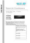
Installation and Operation Manual
Room Air Conditioners
Portable Range
Local Air Conditioners
ECO12P
Register your air conditioner
Re
Model information can be found on the CE
label.
Please register your product online at
www.ecoair.org. For your future
convenience, record the model information
below.
____________________________________
MODEL NUMBER
____________________________________
SERIAL NUMBER
____________________________________
PURCHASE DATE
Congratulations!
You have purchased the very latest in room air conditioner technology. Your
new EcoAir high efficiency room air conditioner will give you many years of
dependable service. Many features have been built into your EcoAir air
conditioner to assure quiet operation, the best circulation of cool, heat, fan & dry
functional controls, and the most economical operation.
CONTENTS
Operation and maintenance
■BS PLUG WIRING ....................................................................................... 1
■SPECIFICATION ........................................................................................ 2
■SUMMARY ................................................................................................ 3
■WORKING PRINCIPLE ............................................................................... 3
■USER NOTICES ......................................................................................... 4
■BEFORE USE .............................................................................................. 5
■STRUCTURE .............................................................................................. 6
■OPERATION METHODS .....,...................................................................... 7
■ NAMES AND FUNCTIONS OF THE REMOTE CONTROL ........................ 10
■OPERATION OF THE REMOTE CONTROL ............................................ 12
■ACCESSORIES AND INSTALLATION OF HEAT EXHAUST HOSE .......... 15
■INSTALLATION INSTRUCTIONS ............................................................... 18
■INSTALLATION OF DRAINAGE HOSE ..................................................... 27
■CARE AND MAINTENANCE ...................................................................... 28
■ELECTRICAL SCHEMETIC DIAGRAM ..................................................... 29
■TROUBLESHOOTING ................................................................................. 30
■AFTER SALES SERVICE ........................................................................... 31
■ORDER FORM ............................................................................................ 32
■SERVICE AND WARRANTY ....................................................................... 33
You must not dispose of this appliance as unsorted waste
or with domestic household waste.
Please observe local regulation for disposal.
Most Local authorities have specific collection systems for
appliances where disposal is free of charge to the end user.
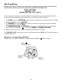
BS Plug Wiring
Wiring Instructions: Should it be necessary to change the plug please note the wires
in the mains lead are coloured in accordance with the following code:
BLUE - NEUTRAL
BROWN - LIVE
GREEN AND YELLOW - EARTH
As the colours of the wires in the mains lead of this appliance may not correspond with the
coloured markings identifying the terminals in your plug, proceed as follows:
1. The BLUE wire is the NEUTRAL and must be connected to the terminal which is marked
with the letter N or coloured BLACK.
2. The BROWN wire is the LIVE and must be connected to the terminal which is marked
with the letter L or coloured RED.
3. The GREEN/YELLOW is the EARTH and must be connected to the terminal which is
marked with the letter E or
or coloured GREEN OR GREEN/YELLOW.
4. Always ensure that the cord grip is positioned and fastened correctly.
If a 13A (BS 1363) fused plug is used it must be fitted with a 13A fuse. If in doubt consult a
qualified electrician.
Wiring for a 13 Amp Plug (BS1363)
Please note. The Earth Terminal is marked with the letter E or
-1-
Earth Symbol.
2
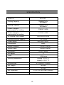
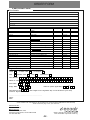
SPECIFICATION
Model no.
ECO12P
Cooling Capacity
12000 BTU/hr
3520watts
Heating Capacity
12000 BTU/hr
3520watts
Power / Ampere
consumption for cooling
1350 W / 6.0A
Power / Ampere
consumption for heating
1170 W / 5.2A
Air Volume (max. speed)
420/380/320 m3/h
Humidity removal capacity
1.00 L/hour
Power supply
220-240V~50Hz
Compressor
rotary
Sound Pressure
55/53/51 dB(A)
Sound Power
65/63/61 dB(A)
Refrigerant
R410A (980g)
Fan speed
3
Timer
1~24 hours
Working temperature
Cooling: 16~35 °C
Heating: 10~27 °C
Exhaust pipe
Ø 150mm x 1500mm
Net Weight
40 Kgs
Gross Weight
45 Kgs
Net Dimension
375 x 755 x 442 mm (WxHxD)
Gross Dimension
437 x 885 x 555 mm (WxHxD)
-2-
SUMMARY
This compact and energy efficient air conditioning unit can be moved to different locations within
your home or office. With its multiple functions of COOL, HEAT, DRY and FAN, this versatile appliance
is the perfect addition to any large space. Its low noise makes it an especially good choice.
Note: Please read this manual carefully before operating the unit. the technical parameters are subject
to change without notice.
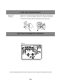
WORKING PRINCIPLE
With the help of the upper motor, the airflow passes through the evaporator and is cooled. With the help
of the lower motor, the airflow passes through the condenser and becomes heated. There is a two duct
system, the heated air is discharged by the rear outlet and the cooled air is discharged from the front.
The flow is guided by the louvre.
The Working Principle
evaporator
cool air
fan motor
capillary
heat air
condenser
-3-
USER NOTICES
Location
Install the unit in a well ventilated area, do not cover the unit.
Do not keep the unit in direct sunlight.
To avoid electrocution, do not install the unit in a damp area and keep away from water.
Make sure the unit is at least 1m away from any television sets.
If the mains lead is damaged, it must be replaced by the manufacturer, its service agent
or a similarly qualified person.
Position the appliance so that its plug is accessible.
Do not use the unit near any gas, fire or oil.
Others
This unit is not to be operated by children, vulnerable people or anyone under the influence
of alcohol or any substance that could cause impairment.
Do not rest anything on top of the unit.
Take care not to stand directly in front of the unit for prolonged periods of time when it is in
COOL mode.
Do not let the air inlet/outlet become blocked, this will lead to the unit malfunctioning.
NEVER insert your hands or stick any object into the air inlet or outlet. .
Make sure the power cord is not damaged as this can be hazardous. If the cord is damaged
it must be replaced by the manufacturer, its service agent or a similarly qualified person.
Do not place the unit on an incline or lay it flat. If the unit is knocked over, pull out the plug
from the wall immediately and inform the seller to arrange a service.
Static press in pipeline ranged from 0Pa to 25Pa.
Ɣ
Ɣ
Do not use insecticide or other sprays near the unit as these can damage the surface
Check the User Manual for instructions on how to dispose of this unit.
-4-
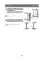
BEFORE USE
GENERAL SAFETY
21/<86(,17+(835,*+7
326,7,2121$)/$7/(9(/
685)$&($1'$7/($67FP
)520$1<2%-(&76)LJ
'21273/$&(2%-(&76217+(
81,7255(675,&7$,5,1/(7287/(7
),*
&/26(/<683(59,6($1<
&+,/'5(1$1'3(76:+(17+(81,7
,6,186(
7+,6$33/,$1&(,6127,17(1'('
)2586(%<3(56216,1&/8',1*
&+,/'5(1:,7+5('8&('
3+<6,&$/6(1625<250(17$/
&$3$%,/,7,(625/$&.2)
(;3(5,(1&($1'.12:/('*(
81/(667+(<+$9(%((1*,9(1
683(59,6,2125,16758&7,21
&21&(51,1*86(2)7+(
$33/,$1&(%<$3(5621
5(63216,%/()257+(,56$)(7<
&+,/'5(16+28/'%(683(59,6('
72(1685(7+$77+(<'2127
3/$<:,7+$33/,$1&(
X
),*
X
),*
ELECTRICAL SAFETY
)25,1'22586(21/<
6:,7&+2))$1'813/8*:+(1
127,186(
'212786(,1+80,'25:(7
(19,5210(176),*
'212738//7+(81,7$/21*%<
7+(&25'
,)7+(6833/<&25',6
'$0$*(',70867%(5(3/$&('
%<$1(/(&75,&,$1256,0,/$5/<
48$/,),('3(562172$92,'
+$=$5'
X
),*
-5-
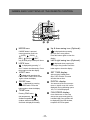
STRUCTURE
Front
Control Panel
Air outlet
Remote control
receiver
Rear
Handle
Upper air inlet grille
Heat air exhaust vent
Lower air inlet grille
Power cord
-6-
OPERATING METHODS
※. USAGE NOTICE
The working range of COOL mode and DRY mode: +16 ćto +35 ć
The working range of HEAT mode: +10 ć to +27 ć
Unpack the Air Conditioner
WARNING
Excessive Weight Hazard
Two or more people are required to move and install the air conditioner.
Failure to do so can result in back or other injuries.
Remove packaging materials
Remove unit from box (Packaging). Remove tape and glue residue from surfaces before turning on
the air conditioner. Rub a small amount of liquid detergent over the adhesive with your fingers.
Wipe with warm water and dry it.
Do not use sharp instruments, alcohol, flammable liquids, or abrasive cleaners to remove tape
or glue. These products can damage the surface of your air conditioner.
Placement requirements:
The appliance shall be installed in accordance with national wiring regulations.
The appliance is for indoor use only,but should not be installed in a laundry.
Place the air conditioner on a smooth level floor that is strong enough to support the unit.
Allow at least 12 inches (50 cm) of air space on all sides of the unit for good air ventilation.
ƎFP
min.
ƎFP
min.
Place the unit in an area where the temperature will not fall below 16℃(61°F). The coils will be covered
with frost at temperatures below 16℃(61°F), and this may reduce performance. (For Cooling)
NOTE: The air conditioner has wheels for easy movement, but it should only be rolled on smooth
and flat surfaces. Do not attempt to roll the air conditioner on carpet or over objects.
-7-
OPERATING METHODS
Names and functions of the control panel
4
2
3
1
5
6
Control panel and functions
1.Power ON / OFF:
Press once to start and press once more to stop the unit.
2.Mode:
Press this button to change the operation mode in order of:
&22/ĺ'5<ĺ)$1ĺ+($7
3."
" " ":
In "COOL" or "HEAT" mode, press" " once, the temperature. will decrease 1 .
Press" " once, the temperature will increase 1℃.The temperature can be selected from 16 ℃
(61°F) ~ 30℃(86°F)
4.Fan:
3UHVVWKLVEXWWRQWRFKDQJHWKHRSHUDWLRQIDQLQRUGHURI/2:ĺ0('ĺ785%2ĺ$872
5. Timer:
Press the timer button to enter the timer setting mode. In this mode, press
arrow or
arrow buttons to adjust the timer settings. The timer setting will increase or decrease by 1 hour
increments. After the timer is set, the unit will display the temperature, if theres no operation for
5 seconds. If the timer function has started, the upper indicator will keep the display status.
Otherwise, it wont be displayed. If the timer mode is active the LED light above the switch
will be illuminated. Press the timer button again to cancel.
6. Sleep:
Press the sleep button to enter into sleep mode. If the controller operates in cooling mode, after
sleep mode is activated, the preset temperature will increase by 2C within 2 hours and then the unit
will operate at this temperature all the time. The sleep function is not available for the fan mode,
drying and auto modes. If sleep function is activated, the LED above the switch will be illuminated.
-8-
OPERATING METHODS
COOL mode 1). Select a place near a door or window, install the exhaust duct.
2). Press "MODE" key to select "COOL" mode.
3). Press"
"or "
" key to set the suitable temp.16℃( 61°F )~30℃(86°F).
HEAT mode
1). Press MODE key to select HEAT mode.
2). Press" "or " " key to set the suitable temp.16℃( 61°F )~30℃(86°F).
DRY mode
Please close the door and windows to obtain the best dehumidifying effect:
Press "MODE" key, select the "DRY" mode, the unit will run in the "DRY" mode, at
the same time, the upper motor is running at the low speed, it is not adjustable.
FAN mode
When the unit runs in FAN mode, you can select 3 speeds.
-9-
NAMES AND FUNCTIONS OF THE REMOTE CONTROL
1
ON/OFF
Press it to start or stop operation.
FAN
2
AUTO
OPER
Press to select operation mode
(AUTO/COOL/DRY/FAN/HEAT).
AIR HEALTH X-FAN
HUMIDITY
FILTER
3
TURBO
MODE
- : Press to decrease temperature
setting.
HOUR
ON/OFF
4
+ : Press to increase temperature
setting.
2
1
ON/OFF
MODE
5
FAN
Press to set fan speed.
3
4
6
Press it to set up & down swing angle. (Optional)
6
5
FAN
8
7
7
HEALTH SAVE ( page 10)
Press it to turn on or off health function. (Optional)
9
10
X-FAN
TEMP
12 TURBO13 SLEEP
TIMER
LIGHT
11
8
14
Press it to set left & right swing angle. (Optional)
9
X-FAN ( page 10)
10
TEMP( page 10)
11
TIMER
Press it to set timer ON/ timer OFF
12
TURBO( page 10)
13
SLEEP( page 11)
14
LIGHT
Press to turn the light on or off
-10-
NAMES AND FUNCTIONS OF THE REMOTE CONTROL
24
FAN
AUTO
OPER
AIR HEALTH X-FAN
HUMIDITY
FILTER
15
23
TURBO
HOUR
16
17
ON/OFF
22
21
18
19
15
20
MODE icon:
20
If MODE button is pressed,
current operation mode icon
(AUTO),
( COOL),
(DRY),
(FAN) or (HEAT
only for heat pump models) will show.
16
is displayed when pressing
the up & down swing button.
Press this button again to clear the
display.
21
LOCK icon:
LIGHT icon:
22
ON or OFF will blink.This area
will show the set time.
SLEEP icon :
23
DIGITAL display:
This area will show the set temperature. In SAVE mode,"SE" will be
is displayed by pressing
the SLEEP button. Press this
button again to clear the display.
19
SET TIME display:
After pressing TIMER button,
is displayed by pressing the
LIGHT button. Press LIGHT button
again to clear the display.
18
Left & right swing icon (Optional):
is displayed when pressing the
left & right swing button.Press this
button again to clear the display.
is displayed by pressing "+"
and - buttons simultaneously. Press
them again to clear the display.
17
Up & down swing icon (Optional):
displayed. During defrosting operation, H1 will be displayed.
TEMP icon:
24
Pressing TEMP button,
(indoor
(set temperature),
ambient temperature)
(outdoor ambient temperature)
and blank is displayed circularly.
FAN SPEED display:
Press FAN button to select the
desired fan speed setting(AUTO-
Low-Med-High).Your selection will
be displayed in the LCD windows,
except the AUTO fan speed.
-11-
OPERATION OF THE REMOTE CONTROL
Remote control description
1
ON/OFF :
Press this button to turn on the unit. Press this button again to turn off the unit.
2
MODE :
Each time you press this button,a mode is selected in a sequence that goes from AUTO,
COOL, DRY, FAN,and HEAT *, as the following:
FAN
HEAT *
COOL
AUTO
DRY
*Note: Only for models with heating function.
After turning on, AUTO mode is defaulted. In AUTO mode, the set temperature will not be
displayed on the LCD, and the unit will automatically select a suitable operation mode in
accordance with the room temperature to make the room comfortable.
3
-:
Press this button to decrease set temperature. Hold it down for above 2 seconds to
rapidly decrease set temperature. In AUTO mode, set temperature is not adjustable.
4
+:
Press this button to increase set temperature. Hold it down for above 2 seconds to
rapidly increase set temperature. In AUTO mode, set temperature is not adjustable.
5
FAN :
This button is used for setting fan speed in the sequence that goes from AUTO,
, to
,
, then back to Auto.
Auto
Low speed
Medium speed
High speed
When setting HIGH fan speed,unit will display TURBO fan speed.
6
(Optional) :
Ɣ Press
button to start or stop up & down swing function.The remote controller
defaults to simple swing condition.(This function is not applicable for some models).
Ɣ Press + button and
button at the same time at unit OFF to switch between
simple swing and static swing;
Ɣ In static swing condition, pressing
changes as below:
blinks for 2 seconds.
button, the swing angle of up & down louver
Ɣ If the unit is turned off during swing operation,the louver will stop at present position.
-12-
OPERATION OF THE REMOTE CONTROL
7 HEALTH SAVE (Optional):
Press the HEALTH part of this button to turn the HEALTH function on or off.
SE is displayed and the unit goes into SAVE operation mode. Press ,
is displayed and
the unit goes into SAVE operation mode. Press SAVE part of the button again to cancel
SAVE function. During SAVE operation, the temperature and fan speed is not adjustable.
※ This function is not available for this unit.
8
(Optional):
Ɣ Press
button to start or stop left and right swing function. The remote control defaults
to simple swing condition.
Ɣ Press + button and
button at the same time at unit OFF to switch between
blinks for 2 seconds.
simple swing and static swing;
Ɣ In static swing condition, pressing
button, the swing angle of left & right louver
changes as below:
Ɣ If the unit is turned off during swing operation,the louver will stop at present position.
※ This function is not available for this unit.
9 X-FAN:
Pressing X-FAN button in COOL or DRY mode,the icon X-FAN is displayed and the
indoor fan will continue operation for 10 minutes in order to dry the indoor unit even though
you have turned off the unit.
After energization, X-FAN OFF is defaulted. X-FAN is not available in AUTO, FAN and
HEAT mode.
10 TEMP:
Pressing this button will give you the options of displaying the indoor setting temperature
or the indoor ambient temperature. When the unit first powers on it will display the indoor
setting temperature. If the temperatures display status is changed it will display the
ambient temperature
. On or within 5 seconds, it will revert to the setting temperature
display.
11 TIMER:
Press TIMER button at unit ON to set TIMER OFF; HOUR OFF blinks. Press TIMER
button at unit OFF to set TIMER ON; HOUR ON blinks. In this case, pressing + or -
button changes time setting. Holding down either button rapidly changes time setting
(time setting range 0.5-24hours). Press TIMER button again to confirm setting; HOUR
ON/OFF stops blinking. If there is not any operation of button within 5 seconds during
HOUR ON/OFF blinking, TIMER setting will be cancelled.
12 TURBO:
Press this button to activate/deactivate the turbo function which enables the unit to
reach the preset temperature in the shortest time. In COOL mod the unit will blow
cooled air at a super high fan speed. In HEAT mode, the unit will blow heated air
at a super high fan speed.
-13-
OPERATION OF THE REMOTE CONTROL
13 SLEEP :
Press this button to go into the SLEEP operation mode. Press it again to cancel this
function. This function is available in COOL, HEAT (Only for models with heating
function) or DRY mode to maintain the most comfortable temperature for you.
14 LIGHT:
Press LIGHT button to turn on the display's light and press this button again to turn off
the display's light. If the light is turned on ,
is displayed. If the light is tunrned off,
disappears.
15 Combination of "+" and "-" buttons: About lock
Press " + " and " " buttons simultaneously to lock or unlock the keypad. If the remote
controller is locked,
is displayed. In this case, pressing any button,
blinks
three times.
16 Combination of MODE and - buttons: to switch between Fahrenheit and centigrade.
At unit OFF, press "MODE " and "- " buttons simultaneously to switch between ć and ̧.
Replacement of Batteries
1.Remove the battery cover plate from the rear of the remote controller.
(As shown in the figure)
2.Take out the old batteries.
3.Insert two new AAA1.5V dry batteries, and pay attention to the polarity.
4. Reinstall the battery cover plate.
ȝ Notes:
Ɣ
When replacing batteries, make sure the ones you are replacing them
with are new and of the right type
Ɣ
If you are not going to use the remote control for a long period of time,
remove the batteries before storing.
Ɣ
Ɣ
Ɣ
The operation should be performed in its receiving range.
It should be kept at least 1 meter away from TV and audio systems
If the wireless remote control stops working, remove the batteries,
wait 30 seconds and then reinsert them. If the control still does not
work, replace the batteries.
-14-
Sketch map for
replacing batteries
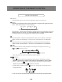
ACCESSORIES AND INSTALLATION OF HEAT EXHAUST HOSE
Ɣ
Length range of the exhaust pipe should be 50 150cm.
It is recommended to use it with the shortest length.
Ɣ
When installing, the exhaust pipe should be as flat as possible.
Do not stretch the pipe or connect it with another exhaust pipe.
This would course abnormal operation.
100cm
Correct installation is as shown in figure (When installing it on
wall, height of hole should be about 40 -100cm from floor).
-15-
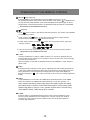
ACCESSORIES AND INSTALLATION OF HEAT EXHAUST HOSE
If the pipe has to be bent, please consider the following
dimensions when installing
55cm
65cm
55cm
An incorrect installation is shown in the following figure
(if the pipe is bent too much, it could easily cause a
malfunction).
-16-
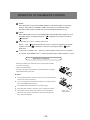
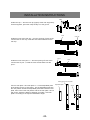
ACCESSORIES AND INSTALLATION OF HEAT EXHAUST HOSE
PARTS INCLUDED ECO12P UNIT & THE FOLLOWING ACCESSORIES:
Remote Control
Flexible Exhaust Hose
Back Plate
Baffle Plate
Installation and Operation Manual
Window Exhaust Adapter
Adjusting Plate
Drain Hose
-17-
Front Plastic Pipe End
Real Grill
Back Plate
INSTALLATION INSTRUCTIONS
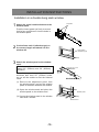
Installation in a double-hung sash window
1
Projection
Attach the guard combined above to the
window panel
Push the insect guard net firmly to ensure
that its four projections fit into the holes in
the window panel.
the foam seal A (adhesive type) to
2 Cut
the correct length and attach it to the
Foam seal A
(adhesive type)
window sill.
the window panel to the window
3 Attach
stool.
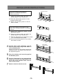
If the inner width of the window is between 22" (559mm) and 24" (609mm)
inclusive.
Cut
The window panel cannot be installed in
windows less than 22" (559mm) wide,
as you will be unable to shut the exhaust
cover.
(1) Remove the adjustment panel from
the window panel, and cut the window
panel to the same width as the window.
(2) Open the window sash and place the
window panel on the window stool
(3) Secure the window panel to the window
stool with 2 screws.
Window panel
22"~ 24"
Window stool
-18-
INSTALLATION INSTRUCTIONS
Adjustment panel
If the inner width of the window is
between 24" (609mm) and 36.8"
(934mm) inclusive.
(1) Open the window sash and place the
window panel on the window sill.
(2) Slide the adjustment panel to fit the
window frame width.
(3) Secure the window panel to the sill
with 3 screws.
If the inner width of the window is between 36.8" (934mm) and 48" (1219mm)
inclusive.
24"~36.8"
Extension panel
(1) Attach the extension panel to the
adjustment panel.
(2) Open the window sash and place the
window panel on the window sill.
(3) Slide the adjustment and extension panels
to fi t the window frame width.
(4) Secure the window panel to the window
stool with 4 screws.
4
Cut the foam seals (adhesive type) A
and B to the proper length and attach it
to the window panel.
Attach foam seal A to the window panel and
extension panel, and attach foam seal B to
the adjustment panel.
36.8"~48"
Foam seal A
(adhesive type)
the window sash securely against
5 Close
the Window panel.
the foam seal to an appropriate
length and seal the opening between the
6 Cut
top of the inner window sash and the
outer window sash.
7 Attach a bracket with the screw.
Bracket
-19-
INSTALLATION INSTRUCTIONS
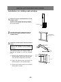
Installation in a sliding sash window
the guard combined above to the
window panel.
1 Attach
Push the insect guard net firmly to ensure
that its four projections fit into the holes in
the window panel.
Projection
the foam seal A (adhesive type) to
the correct length and attach it to the
2 Cut
window frame.
Foam seal A
(adhesive type)
the window panel into the window
3 Install
frame.
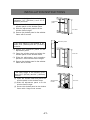
If the inner height of the window is
between 22" (559mm) and 24" (609mm)
inclusive.
Cut
The window panel cannot be installed in
windows less than 22" (559mm) high, as
you will be unable to shut the exhaust
cover.
(1) Remove the adjustment panel from the
window panel, and cut the window panel to the same height as the window.
Window
panel
22"~24"
(2) Open the window sash and place the
window panel on the window frame.
(3) Secure the window panel to the window
frame with 2 screws.
-20-
INSTALLATION INSTRUCTIONS
If the inner height of the window is
between 24" (609mm) and 36.8"
(934mm) inclusive.
Adjustment
panel
(1) Open the window sash and place the
window panel on the window frame.
(2) Slide the adjustment panel to fit the
window frame height.
24"~36.8"
(3) Secure the window panel to the window
frame with 3 screws.
Extension panel
If the inner height of the window is between 36.8" (934mm) and 48" (1219mm)
inclusive.
(1) Attach the extension panel to the
adjustment panel.
(2) Open the window sash and place the
window panel on the window frame.
36.8"~48"
(3) Slide the adjustment and extension
panels to fit the window frame height.
(4) Secure the window panel to the window
frame with 4 screws.
If the inner height of the window is between 36.5" (927mm) and 64" (1625mm)
inclusive.
(1) Open the window sash and place the
window panel on the window frame.
(2) Slide the adjustment panel to ¿t the
window frame height.
(3) Secure the window panel to the window
frame with 4 large wood screws.
-21-
Window slider
bracket
36.5"~64"
INSTALLATION INSTRUCTIONS
the foam seals (adhesive type) A and
B to the proper length and attach them
4 Cut
to the window panel.
Attach foam seal A to the window panel and
extension panel, and attach foam seal B to
the adjustment panel.
the window sash securely against
5 Close
the Window panel.
Foam seal A
(adhesive type)
the foam seal to an appropriate
length and seal the opening between the
6 Cut
side of the inner window sash and the
outer window sash.
7 Attach a bracket with the screw.
Bracket
-22-
INSTALLATION INSTRUCTIONS
clasp
Install rear clip aim the rear clip (upper) at the rear clip (lower),
fix them together, press the clasp forcibly in to the groove.
hose
rear clip
Install the hose at the rear clip aim the opening of hose at the
round mouth of rear clip, rotate the hose anticlockwise into the
rear clip.
joint 1
hose
Install the hose at the joint 1 aim the opening of hose at the
round mouth of joint 1, rotate the hose anticlockwise into the
joint 1.
sliding groove of rear plate
Connect rear plate 1 and rear plate 2 fix the adjustable plate adjustable plate
at the sliding groove of rear plate 1, put the adjustable plate into
the rear plate to enable the adjustable plate slide inside the rear
plate, then connect the rear plate 2 and fix the rear plate 1 and 2
with screw. Adjust the distance between rear plate 1 and rear
plate 2 according to the required installation height.
-23-
screw
INSTALLATION INSTRUCTIONS
screw
The length of rear plate 1 and rear plate 2 can be
adjusted according to users requirement. Loosen
the screws fixing the rear plate 1, rear plate 2 and
adjustable plate to move the rear plate 2 and
adjustable plate (can slide freely in the sliding
groove of rear plate 1 and rear plate 2) to the
required length, and then fix the rear plate 1 and
rear plate 2 with screws.
rear plate 2
screw
This length can be adjusted according
to users requirement
adjustable plate
(can slide in the
sliding groove of
rear plate 1 and
rear plate 2)
rear plate 1
screw
Install protective grille aim the protective grille at
the air outlet of rear plate 1 and then press the clasp
of protective grille inwards to fasten the rear plate 1.
clasp of protective
grille
Install the exhaust hose assembly at the rear
plate aim the rear clip of exhaust hose
assembly at the air outlet of rear plate 1 and
then press the clasp of rear clip into the groove
of protective grille firmly.
screw
clasp of protective grille
rear clip
-24-
screw
INSTALLATION INSTRUCTIONS
Install exhaust hose assembly to the rear as in Picture 1. Simply slot Joint 1 downwards on the air
outlet Picture 2.
air outlet groove of back plate
Picture 1
joint 1
Picture 2
When the unit is not in use and using the window kit remove hose and close the grille with the
"baffle plate" over the hole.
clasp of protective grille
screws
baffle (air outlet)
-25-
INSTALLATION INSTRUCTIONS
Filter 2 hold the buckle of filter 2 to pull it outwards.
filter 2
buckle of filter 2
Install cable hook press the clasp at the upper side of back plate, assemble the first cable hook
downwards into the groove of upper clasp; press the clasp at the lower side of back plate, assemble
the second cable hook upwards into the groove of lower clasp.
clasp
wire hook
Install remote control boxthe opening of remote control box is upward, aim the groove of the
back side at the groove of the left side plate, and then assemble the remote controller box.
remote controller box
groove
-26-
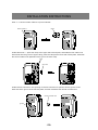
INSTALLATION OF DRAINAGE HOSE
Installation of drainage hose (as shown in the following figure):
Note: The drainage hose must be installed before operating the unit otherwise a
blockage may occur affecting the normal operation of the unit.
1. Remove drain cap (A) from drain port (B).
A. Drain cap
B. Drain port
A
B
2. Attach the drain hose clamp (C) to the back panel of the air conditioner near the drain port (B) with the
screw provided.
B. Drain port
C. Drain hose clamp
C
A
B
3. A ttach one end of the drain hose (D) to the drain port (B) with the clip (E). Make sure the hose is
fully inserted into the drain port (B).
B. Drain Port
C. Drain hose clamp
D. Drain hose
E. Drain hose clips
F . Rubber plug
C
E
F
B
D
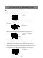
4. Insert the rubber plug (F) into the other end of the drain hose (D) and secure with clip (E).
5. Snap the free end of the drain hose (D) into the drain hose clamp (C).
6. During the process of cooling , excess condensation will occur inside the unit, Although the water will be
evaporated by the coil for maximum efficiency. In very warm temperature or high humidity condition, it will
require water drianage. This will be indicated as an "H8" error.
7. Remove the drain hose (D) from the clamp (C) and release the excess water at downward slope by removing the
rubber plug (F).
8. Completely drain water and the unit should resume operation. Secure the plug and hose back in position
B. Drain Port
C. Drain hose clamp
D. Drain hose
C
D
B
F
-27-
F. Rubber plug
CARE AND MAINTENANCE
Mobile unit
Casters underneath the unit enable
it to be moved easily within a
room.
Air inlet grille
WARNING
Before maintenance, please
pull out the plug and cut
off power supply to avoid
electric shock.
Clean the air filter
Performance of the unit will be affected if there is constant gathering
dust on the air filter. You will need to clean this every two weeks
if this is the case.
Filter supporter
Disassembly
Clean
Ɣ
Draw out filter supporter and take out filter
Ɣ
Wash the filter with a soapy spray.
and shake it, or immerse it into gentle soapy water,
then drip it in the shade.
-28-
CARE AND MAINTENANCE
Clean the air
conditioner
Please use a cloth that is slightly moistened with water at a temperature
below 40 °C . Do not use gasoline, diesel oil or a congeneric substance
to clean the unit. Before cleaning, please pull out the power plug.
S
GA
ELECTRIC SCHEMATIC DIAGRAM
ECO12P:
The circuit diagrams above are only for reference, which are subject to change without notice.
-29-
TROUBLESHOOTING
If malfunctions occur, please check the following before maintenance:
Troubles
Possible Causes
The air conditioner doesn't
start.
Solutions
The power supply is not connected
1.Insert the power plug tightly.
properly.
The power plug is not inserted tightly. 2.Replace the power plug or socket.
There is a the malfunction of the
power plug or socket.
The fuse is blown.
3.Have an electrician replace the
fuse.
Although it was set to COOL
mode, there is no cool air.
1. The room temp. is lower
than the set temp.
2. The evaporator frosts.
1.This is normal.
2.Unit is running in defrosting operation, it will resume running in
original operation after defrosting.
Although it was set to DRY
mode, there is no cool air.
1. The evaporator has
frosted.
1.Unit is running in defrosting
operation, it will resume running in
original operation after defrosting.
The LED displays"
".
1. Low voltage over current
protection.
Cut off power supply, after 10
minutes, turn on the unit, if " "
is still displayed, please contact
your dealer for technical advice.
The LED displays"
".
High humidity causing exce- 1. Drain excess water from drianage
ssive condensation inside the hose (see installation instructions)
2.If the malfunction still persists,
unit.
please contact your dealer for
technical advise.
The LED displays"
".
Malfunction of evaporator te- Check if indoor room temperature
sensor is connected properly
mperature sensor.
The LED displays"
".
Malfunction of evaporator te- Check if the evaporator temperature
mperature sensor.
is connected properly.
The LED displays"
".
1. The wiring terminal between
outdoor condenser temperature
sensor and controller was loosened or poorly connected;
2. Theres short circuit due to the
trip-over of the parts on controller;
3.Outdoor condenser temperature
sensor was damaged .
4. Main board was broken.
- 30-
1.Remove the temperature sensor,
then re-insert it to make it stable.
2.Check the circuit on the controller.
3.Replace the temperature sensor.
4.Replace the main board after
repair.
Ɣ Meaning of crossed-out wheeled unit: Do not dispose of electrical appliances
as unsorted municipal waste, use separate collection facilities.
Ɣ Contact you local council for information regarding the collection systems
available.
Ɣ If electrical appliances are disposed of in landfills or dumps, hazardous substances
can leak into the ground water and get into the food chain,damaging your health and
well-being.
Ɣ When replacing old appliances with new ones,the retailer is legally obligated to
take back your old appliance for disposal at least free of charge.
Ɣ It is prohibited to dispose of this appliance in domestic household waste.
For disposal there are several possibilities:
a) The councils have has established collection systems, where electronic waste can
be disposed of at least free of charge to the user.
b) When buying a new product, the retailer will take back the old product at least
free of charge.
c) The manufacturer will take back the old appliance for disposal at least free of
charge to the user.
d) As old products contain valuable resources, they can be sold to scrap metal dealers.
Wild disposal of waste in forests and landscapes endangers your health when hazardous
substances leak into the ground-water and find their way into the food chain.
AFTER SALES SERVICE
Ɣ If any quality problems or any other problems exist, please contact your dealer.
-31-
ORDER FORM
Post Order Form
Your Details
Company Name:
Name:
Address:
Post code:
Telephone:
Mobile:
Fax / Email:
Model Number
Description of Item
Quantity
£Amount
Unit Price
Filters
12P-58
Real Filter & Fixer
£15.00
12P-54
Side Filter
£15.00
12P-68
Remote Control
£29.94
Exhaust Accessories
12P-78
Exhaust Host (1.5m)
£24.96
12P-80
Tube for continuous drainage
£6.96
Other Accessories
12P-41
Caster Wheels
£5.94
12P-71 & 12P-72 & 12P-73 &12P-74
PVC window Kit Assy
£29.94
12P-76 & 12P-77
Window Exhaust Adapter Assy
£15.00
12P-79
Front Plastic Pipe End
£12.96
12P-75
Real Grill
£12.96
Sub Total
Standard Delivery (Free)
Next Day Delivery (Call)
Total
Payment Details (Please tick one below)
Credit
Visa
or Debit Card
Master Card
or Cheque
Solo
Visa Electron
Card Number:
Name on card:
Issue Date:
Expiry Date:
Card Security No:
/
/
Issue No (where applicable):
/
(Last 3 digits on the signature strip on the reverse of your card)
Customer Signature:
...............................................................
Name:
Date:
* Price includes VAT and shipping to UK mainland only (except Scottish Highlands and remote areas)
*Note: Please see page 17 for your reference.
Fax Form To Us
Fax: 0845 388 9313
Mail Form To Us
EcoAir Unit 7 Propeller Park,
400 North Circular Road, London NW10 0AB
Tel: 0845 388 0005
Order Today By Fax, Post Or Via Online
More Information: http://www.ecoair.org
-32-
SERVICE AND WARRANTY
ONE (1) YEAR LIMITED WARRANTY
Save This Warranty Information
EcoAir guarantees this product free from defects in materials and workmanship for a period
of one (1) year from the date of purchase. Coverage is valid only with proof of purchase.
This unit must be operated under conditions as recommended, within the voltage range
indicated on the unit. Any attempts made to service or modify the unit, will render this
WARRANTY VOID. The actual product may differ slightly from the illustration. This warranty
is in addition to, and does not affect, your statutory rights.
If the unit is modified or mis-used, this could void the warranty.
For further information, please contact 0845 388 0007.
This product has been manufactured to comply with the EC Directives 2006/95/EC and
2004/108/EC.
/
ments
WEE/EC2601UR
Copyright Reserved
C174
-33-