1
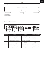
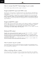
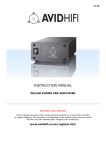
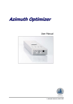
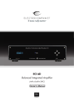
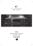
12 11 10 9
8 7 6 5
4 3 2 1
1 2 3 4
5 6 7 8
9 10 11 12
ECP 2
High Performance Balanced Phono Stage
Owner's Manual
Version 1.0
EN
ENGLISH
ENG
Welcome to the world of Electrocompaniet!
We thank you for choosing an Electrocompaniet high-end product.
At Electrocompaniet we are relentlessly focused on developing audio
equipment that is capable of bringing the fabulous experience of the
concert hall into the very heart of your home.
Our aim when developing and testing new products is to ensure that
the wonderful richness of tone and every nuance of feeling and emotion of a piece of music is delivered to you just as the artist intended.
We continually strive to give you the very best musical listening experience available whatever your preferred musical genre.
Sincerely yours
Mikal Dreggevik
CEO
2
ENG
Precautions
• Before connecting the AC power cord to the appliance, make sure the voltage designation of the
appliance corresponds to the local electrical supply. If you are unsure of your power supply, contact your
local power company. The acceptable power input range is AC ~100V-240V, 50/60Hz.
• Unplug the power cord if you are not going to use the product for an extended period of time. Hold the
power when unplugging. Do not pull on the cord.
• To ensure proper ventilation around this product, do not place this product on a sofa, bed or rug. When
installing this product on a wall or bookshelf, you need to provide appropriate space: we recommend leaving 3 - 5 cm (1 - 2 inches) of free space at the top, the sides and the rear.
• High temperature will lead to abnormal operation of this unit. Do not expose this unit or batteries to direct
sunlight or near other heating objects.
• Condensation may occur when moving the ECP 2 from a cold location to a warm one, or vice versa. Should
this occur, the ECP 2 may not operate properly. In such a case please turn the unit on for 1-2 hours to facilitate
moisture evaporation.
Important Safety Instructions
1)
2)
3)
4)
5)
6)
7)
Read these instructions.
Keep these instructions.
Heed all warnings.
Follow all instructions.
Do not use this device near water.
Clean only with dry cloth.
Install in accordance with the manufacturer’s instructions.
Do not install the unit in a small and closed rack or shelf.
8) Do not install near any heat sources such as radiators, heat registers, stoves, or other apparatus
(including amplifiers) that produce heat.
9) Do not defeat the safety purpose of the polarized or grounding-type plug. A polarized plug has two
blades with one wider than the other. A grounding type plug has two blades and a third grounding prong.
The wide blade or the third prong is provided for your safety. If the provided plug does not fit into your
outlet, consult an electrician for replacement of the obsolete outlet.
10) Protect the power cord from being walked on or pinched, particularly at plug, receptacle, and the point
where it exits from the apparatus.
11) Only use attachments/accessories specified by the manufacturer.
12) Unplug this device during lightning storms or when unused for long periods of time.
13) Refer all servicing to qualified service personnel. Servicing is required when the device has been damaged in any way, such as power-supply cord or plug is damaged, liquid has been spilled or objects have
fallen into the device, the device has been exposed to rain or moisture, does not operate normally, or has
been dropped.
3
ENG
Warning:
To avoid risk of fire or electric shock, do not expose this appliance to rain or moisture. Verify line
voltage before use. Do not remove cover. No user serviceable parts inside. Refer servicing to qualified
service personal. The warranty is void if the product is tampered with by non-authorised personnel.
Use only authorized Electrocompaniet service center.
The contents of the carton
•
•
•
•
•
1
1
1
1
1
pc.
pc.
pc.
pc.
pc.
Electrocompaniet ECP 2 phono stage
AC main cord
Inspection card
Spare main fuse
Owner’s manual
Set up procedure
Before connecting the ECP 2 phono stage to the AC Power outlet, check that the main voltage indicated
on the rear panel corresponds to the line voltage in the country were you intend to use the unit.
How to avoid damages
Do not under any circumstances connect or disconnect equipment when power is turned on. The design
of the RCA plug generates a huge transient when inserted. Connecting or disconnecting equipment with
the power on can result in severe damage to the phonostage, amplifier(s) and loudspeakers.
How to avoid noise problems
The ECP 2 phonostage contains delicate circuits that are to magnetic stray fields. The unit should not be
placed near power voltage transformers, TV sets etc. Care should also be taken regarding placement of
the interconnect and earth cable(s). Do not run interconnect and earth cable(s) in parallel with main cords
or speaker cables. Keep interconnect and earth cable(s) as short as possible.
How to avoid possible antenna problems
In some set-ups hum may occur when you connect the radio, VCR or TV to your system. The problem is
caused by DC voltage coming from your antenna. Please contact your cable network operator.
4
ENG
Front panel
1
2
1. Power button
2. Power indicator
12 11 10 9
8 7 6 5
4 3 2 1
1 2 3 4
5 6 7 8
9 10 11 12
Rear panel connections
12 11 10 9
1
8 7 6 5
2
4 3 2 1
1 2 3 4
3
5 6 7 8
9 10 11 12
4
5
6
7
8
Connector
Name
Used for
1
Ground screw
Grounding wire
2
DIP switch array - Right channel
Adjusting the phono stage
3
RCA input Left/Right channel
Turntable connection
4
DIP switch array - Left channel
Adjusting the phono stage
5
XLR balanced output - Right channel
Balanced Turntable
connection
XLR / balanced audio
cable
6
RCA line output Left/Right channel
Unbalanced Turntable
connection
RCA / 75-ohm coaxial
cable
7
XLR balanced output - Left channel
Balanced Turntable
connection
XLR / balanced audio
cable
8
AC power cord socket
Input power
Supplied power cable
5
Connection type/Cable
RCA / 75-ohm coaxial
cable
ENG
How to connect the ECP 2 phonostage to your system
Please read this page carefully and refer to page 5 as reference.
Single ended RCA input and GND screw
The RCA input connects the phono cartridge through the arm cable and fixed or detachable RCA
interconnects, to your ECP 2 phono stage. Be sure to use high quality shielded interconnect cables
for this purpose.
In addition, most turntables is equipped with a separate grounding wire. This connects the earth
plane of the turntable chassis, the tone arm and the phono cartridge to the earth plane (GND) of
the phono stage. As a default, connect the grounding wire (if there is one) to the phono stage, but
be aware that in some (very rare) instances you may experience less noise (hum) with the grounding wire detached.
Single ended RCA output
The RCA output connects your ECP 2 phono stage to your line stages, pre amplifier, or integrated amplifier. Use a high quality interconnect cable for best result. If your line stage, pre amplifier or integrated
amplifier have a XLR input option, use the optional XLR output instead, for better sound quality.
The ECP 2 has a fixed (high) output, so DO NOT connect it directly to a power amplifier. This may
cause damage to your power amplifier and loudspeakers.
Balanced XLR output
The XLR output connects your ECP 2 phono stage to your line stages, pre amplifier, or integrated
amplifier. Use a high quality interconnect cable for best result.
The balanced output can only be used with line stages, pre amplifiers and integrated amplifiers
that have this input option. Use an XLR interconnect with GND on pin 1, + on pin 2 and – on pin
3. If your line stage, pre amplifier or integrated amplifier does not have a XLR input option use the
optional RCA output instead.
The ECP 2 has a fixed (high) output, so DO NOT connect it – directly - to a power amplifier. This
may cause damage to your power amplifier and loudspeakers.
How to power up your system
You should always power up your system the following way: Signal sources (CD players, tuners
DACs, phono stages etc.) first. Then turn on line stage / preamplifier / integrated amplifier. Finally
turn on potential power amplifier(s).
When switching off your system
Follow the procedure for powering up in reverse. Start by turning off potential power amplifier(s),
then turn off line stage / preamplifier / integrated amplifier before finally turning off signal sources.
6
ENG
Adjusting the ECP 2 phono stage for best performance
The ECP 2 phono stage is built to work with a majority
of the phono cartridges made today. High- and low-output Moving Coil (MC), Moving Magnet (MM), Moving
Micro Cross (MMC) and Moving Iron (MI) cartridges will
all work well with this unit. To give every different cartridge optimal working conditions the ECP 2 phono stage
is highly adjustable. All adjustments can be performed
on the DIPswitch array (mouse piano) on the rear panel.
12 11 10 9
8 7 6 5
4 3 2 1
1 2 3 4
5 6 7 8
9 10 11 12
Operating the DIPswitch array
A DIPswitch is a small mechanical switch. It is often placed together with other DIPswitches, in an array.
On the ECP 2 there are two arrays of 12 switches, one for each channel. In the down position the
switch is ON and in the up position the switch is OFF. It is not easy to operate the DIPswitches with
your fingers, so some sort of pencil should be used. There are actually special tools for this purpose,
but a pencil or a pen will do the job just as well.
A tip before we get started
Since all the variable settings are located in the DIPswitch array on the rear panel of the phono stage, it
is practical to place the ECP 2 so you have access to these switches, during the initial “tuning” period.
If the phono stage is to be placed in a rack, simply place it with the rear panel pointing to the front of
the rack. Make sure to turn the volume all the way down, or change the input on your line stage / pre
amplifier / integrated amplifier, when operating the DIP swiches!
When you are content with the settings and the sound quality of your turntable playback system, simply
turn the phono stage back around. And enjoy!
7
ENG
Gain settings - DIPswitches 10 - 11 -12
The output of different phono cartridges may vary a lot. There are low output moving coil cartridges with as little as 0,05 mV output and there are high output moving magnet cartridges with
up against 10,00 mV output. The ECP 2 will work with both of these extremes, and everything in
between. With cartridges having very low output, you simply have to crank up the volume on your
amplifier a little more.
“To find the amplification factor (ratio) you need - divide 1,0 V RCA (2,0 V XLR) (to match most
modern line sources) with the output of your cartridge. Go for the closest gain setting (above (if your
line stage can handle the voltage) or below) that result.”
Example:
If your cartridge have an output on 2,2 mV –
you will need; 1,0 V / 2,2 mV = 454 x amplification.
Go up to 944x/59,5 dB gain, or down to 372x/51,4 dB.
The phono stage will then amplify the signal to:
2,2 mV x 944x = 2,08 V (RCA) or
2,2 mV x 372x = 0,81 V (RCA).
The gain of the ECP 2 phono stage is set by adjusting the tree DIPswitches labeled GAIN (number
10 - 11 -12) on the back of your unit. With these tree switches, you may get a variety of different
gain settings. (For XLR output – add 6 dB gain).
X
Gain
dB
Amplification
factor (ratio)
DIPswitch 10
( +20 dB)
DIPswitch 11
( -10 dB)
DIPswitch 12
( -5 dB)
71,4
3.715 x
X
-
-
66,4
2.089 x
X
-
X
61,4
1.175 x
X
X
-
59,5
944 x
X
X
X
51,4
372 x
-
-
-
46,4
209 x
-
-
X
41,4
120 x
-
X
-
39,8
98 x
-
X
X
= ON (Down)
- = OFF (Up)
Resistance loading (RL) - DIPswitches 4 - 5 - 6 - 7 - 8 - 9
Like output, the internal resistance of cartridges may vary a lot. Check the cartridges specifications
sheet for the cartridges internal resistance/coin resistance in Ohms, and the manufacturer’s recommendations for loading in Ohms.
Theoretically a cartridge should “be loaded” with an input resistance 10 -20 times greater than its own
internal resistance / coin resistance. The input resistance, divided by the output resistance of the source,
is called damping factor. Like all things theoretical, this setting may not necessarily give you the best
sound quality - or the sound quality you are looking for. Some cartridges sound better with a dampening
factor greater than 20. Fortunately, you may “play around” with the resistance settings without causing
damage to the cartridge or the phono stage. Find the setting that suits you the best.
The resistance loading (RL) of the ECP 2 phono stage is set by adjusting the six DIPswitches labeled
RL (number 4 - 5 - 6 - 7 - 8 - 9) - on the back of your unit. With six DIPswitches - and six fixed values of resistors - you get a variety of different usable settings:
8
ENG
X
Resistance
Ω (Ohm)
DIPswitch 4
(2k7 Ω)
DIPswitch 7
(100 Ω)
DIPswitch 8
(220 Ω)
DIPswitch 9
(470 Ω)
47.000
-
-
2.553
X
-
832
-
X
-
-
-
-
786
-
X
X
-
-
-
636
X
X
-
-
-
-
618
-
X
-
X
-
-
609
X
X
X
-
-
-
573
-
X
X
-
X
-
521
-
X
-
X
X
-
503
X
X
-
X
-
-
475
-
X
X
X
X
-
473
X
X
X
-
X
-
437
X
X
-
X
X
-
404
X
X
X
X
X
-
384
-
X
-
-
-
X
336
X
X
-
-
-
X
328
-
X
X
-
-
X
292
X
X
X
-
-
X
275
-
X
-
X
-
X
250
X
X
-
X
-
X
211
X
X
X
X
-
X
229
-
X
X
X
-
X
156
-
X
-
-
X
X
147
X
X
-
-
X
X
110
-
X
X
-
X
X
106
X
X
X
-
X
X
56
-
X
-
X
X
X
55
X
X
-
X
X
X
10
-
X
X
X
X
X
10
X
X
X
X
X
X
= ON (Down)
DIPswitch 5 DIPswitch 6
(H/L)
(47 Ω)
- = OFF (Up)
For high output cartridges, the standard input resistance (RL) - set by the “Recording Industry
Association of America (RIAA)” - is 47 kOhms. This value will work very well with a large majority of
the Moving Magnet (MM), Moving Iron (MI), Moving Micro Cross (MMC) and high output Moving Coil
cartridges out there. However, some cartridges especially high output MCs and some MMCs will sound
better with a harder (lower) resistance loading. The ECP 2 is therefore equipped with an optional 2,5k
Ohm loading on its MM input.
The input resistance (RL) for high output cartridges is set by adjusting the DIPswitch labeled MM RL 4.
DIP 5 is set in the OFF position to disables the low value resistor array - so the setting of DIP 6 - 7 - 8 9 becomes without importance. Se the top two lines in the table above.
9
ENG
Capacitance loading (CL) - DIPswitches 1 - 2 - 3
To compensate for the high inductance in MM, MI and MMC cartridges, arm cables and interconnect cables (that will cause peaks in the high frequency range), the ECP 2 is equipped with capacitive loading on its input. Check the cartridges instruction manual for the recommended setting for
your cartridge. Like the resistor loading above, the capacitive loading is a subjective setting. You
may “play around” with the capacitive loading without causing damage to the cartridge or the
phono stage. Find the setting that suits you the best.
With DIPswitches 1, 2 and 3 one can adjust the input capacitance from 0 to 350 pF (picoFarad).
Low output cartridges using low resistance loading do not need to be capacitance loaded. In these
cases, set capacitance to zero (DIP 1-2-3 = OFF).
Capacitance
pF
DIPswitch 1
(50 pF)
DIPswitch 2
(100 pF)
DIPswitch 3
(200 pF)
0
-
-
-
50
X
-
-
X
-
100
X
150
X
X
-
200
-
-
X
250
X
-
X
300
-
X
X
350
X
X
X
= ON (Down)
- = OFF (Up)
Using your ECP 2 phono stage
Press the power button on the front panel to turn the unit on. The blue E power indicator will ignite.
Press the power button one more time to turn the unit off.
The phono stage will sound slightly better after a warm up period, so do not turn it off for short
pauses in your listening. Some users leave their phono stages turned on permanently, but we recommend turning the unit off when leaving the residence.
Power indicator
Power button
Thank you for your attention.
12 11 10 9
8 7 6 5
4 3 2 1
1 2 3 4
5 6 7 8
9 10 11 12
10
ENG
Technical specifications ECP 2
The following technical data were measured on randomized test objects and are typical data.
All measurements are made at 120V / 240V // 50Hz / 60Hz
Gain @ 1 kHz RCA:............................................................................Adjustable 39,8 – 71,4 dB
Gain @ 1 kHz XLR:..............................................................................Adjustable 45,8 – 76,4 dB
Resistance loading (RL):........................................................................Adjustable 10 Ω – 47 kΩ
Capacitive loading (CL):.......................................................................Adjustable 0 – 350 pF
Maximum output level: ............................................17.5 V rms (+ 25 dB V)
Overload margin:...................................................> 31 dB @ 1 kHz
Output impedance:.................................................100 Ω single-ended, 200 Ω balanced
Frequency response:................................................20 – 20 kHz +/- 0.2 dB
RIAA Correction Accuracy:.......................................+/- 0.1 dB
Subsonic filter:........................................................-3dB @ 11 Hz, 24 dB/octave
Channel separation:................................................> 85 dB, 20 – 20 kHz
THD + Noise:.........................................................< 0.003 % @ 1 kHz
S/N-R:...................................................................96 dB, 1 kHz, A-weighted, ref. 10 dB V output
S/N-R:..................................................................91 dB, 1 kHz, A-weighted, ref. 5 mV input
S/N-R:...................................................................67.4 dB, 1 kHz, A-weighted, ref. 500 µV input
Dimensions
Width ....................................................................................................465 mm / 18.3 inches
Depth ....................................................................................................371 mm / 14.6 inches
Height ..........................................................................................................78 mm / 3 inches
Weight..............................................................................................................9 kg / 19.8 lbs
*The manufacturer reserves the right to alter these specifications without further notice.
11
ENG
Product registration
Please consider registering your product with Electrocompaniet.
Registering will make sure you are informed about important information about your Electrocompaniet
product, including notifications when a new firmware version is available for your system.
Please go to http://members.electrocompaniet.no register your product.
If Service is needed
Your dealer will have all relevant information regarding the service centers in your area, and will ensure that
your unit is serviced with minimum delay. It is our general policy to have your unit returned to you within five
working days. This is an average time, and can vary locally, depending on the workload at that particular
service station. If, for some reason, there are no service facilities available in your country, please ship the
unit to the following address:
Electrocompaniet as,
Breivikveien 7,
N-4120 Tau,
Norway
Web: www.electrocompaniet.no
Service department: www.electrocompaniet.no/support
The end user is responsible for all shipping charges, insurance, re-importation and duty charges.
When shipping a product to the factory for service, always include the following:
1.
2.
3.
4.
A sales slip or other proof of purchase if repair is claimed under warranty.
A proforma invoice with value of goods, stating that the ECP 2 is returned to Norway for repair.
An accompanying letter describing faults, symptoms, or problems with the unit.
Always ship the unit in its original carton and packaging material to prevent damage in transit.
Electrocompaniet will not cover damages incurred in transit. If you require further information concerning the
operation of the unit, or if you have any questions related to service, please do not hesitate to contact your
dealer or your national distributor.
User Manual Updates Online
An updated version of the User Manual may be available online at the Electrocompaniet web site.
Occasional updates are needed to reflect new features added to the player since the User Manual was
printed. As future firmware updates bring in new features and functions, the online version of the User
Manual will be updated accordingly.
12
ENG
13
ENG
14
ENG
15
DEALER
STICKER
HERE
LOCAL DEALER
Warning!
To avoid risk of fire or electric shock, do not expose this appliance to rain or moisture.
Verify line voltage before use.
Do not remove cover. No user serviceable parts inside.
Refer servicing to qualified service personal.
The warranty is void if the product is tampered with by non-authorised personnel.
Use only authorized Electrocompaniet service center.
Made in Norway
www.electrocompaniet.no