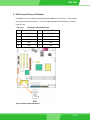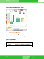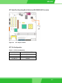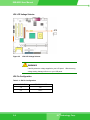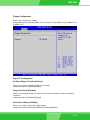
1
IEI Technology Corp.
IMB-8550
Micro-ATX Intel® Pentium® M Embedded
Motherboard
User Manual
Rev. 1.0 January 2006
IMB-8550
Revision History
Title
IMB-8550 Micro-ATX Pentium M Embedded
Motherboard User Manual
Revision Number
Description
Date of Issue
1.0
Initial release
February 2006
Copyright Notice
The information in this document is subject to change without prior notice in order to improve
reliability, design and function and does not represent a commitment on the part of the manufacturer.
In no event will the manufacturer be liable for direct, indirect, special, incidental, or consequential
damages arising out of the use or inability to use the product or documentation, even if advised of
the possibility of such damages.
This document contains proprietary information protected by copyright. All rights are reserved. No
part of this manual may be reproduced by any mechanical, electronic, or other means in any form
without prior written permission of the manufacturer.
Trademarks
IBM PC is a registered trademark of International Business Machines Corporation. INTEL is a
registered trademark of INTEL Corporation. AMI is registered trademarks of American Megatrends
Inc. Other product names mentioned herein are used for identification purposes only and may be
trademarks and/or registered trademarks of their respective owners.
Page 22
Page
IEI® Technology, Corp.
IMB-8550
Table of Contents
Revision History ·························································································································· 2
Motherboard User Manual ·········································································································· 2
Copyright Notice ·························································································································· 2
Trademarks··································································································································· 2
Table of Contents ························································································································· 3
List of Tables ································································································································ 7
List of Figures ······························································································································ 8
CHAPTER 1 INTRODUCTION
Product Overview ·····················································································································1-2
The IMB-8550 Embedded Motherboard················································································· 1-2
IMB-8550 Board Overview ······································································································· 1-4
Technical Specifications ·········································································································1-5
System Monitoring ··························································································································· 1-8
Package Contents ··························································································································· 1-9
Optional Accessory Items ················································································································ 1-9
CHAPTER 2 FUNCTIONAL DESCRIPTION
2.1
CPU, Memory, and Intel Chipsets ·················································································· 2-2
CPU ················································································································································· 2-2
Memory ··········································································································································· 2-3
Intel 855GME Chipset ····················································································································· 2-3
Block Diagram···························································································································2-4
Important Features ···················································································································2-5
2.2
External Interfaces ··········································································································2-7
List of All Interface Connectors ········································································································ 2-8
2.2.1 Internal Connectors ······································································································2-10
Page 3
IMB-8550
2.2.2 Rear Panel Connectors ································································································2-35
2.3
Onboard LED ·················································································································2-39
CHAPTER 3 INSTALLATION
3.1
Considerations Prior to Installation ·············································································· 3-2
Preparing Your Motherboard············································································································ 3-2
Installation Notices ·························································································································· 3-2
Unpacking Precautions ············································································································3-3
3.2
Jumper Settings ··············································································································3-4
JP1 (Clear CMOS)··························································································································· 3-4
JP1 Pin Configuration ······················································································································ 3-5
JP4 (Compact Flash Master/Slave Setting) ····················································································· 3-6
JP4 Pin Configuration ······················································································································ 3-6
JP7 Serial Port Operating Mode Selection (RS-232/422/485 Converter) ········································ 3-7
JP7 Pin Configuration ······················································································································ 3-7
JP8 LCD Voltage Selector ··············································································································· 3-8
JP8 Pin Configuration ······················································································································ 3-8
3.3
External Switches and Indicators ················································································· 3-9
CN3 (PWR/HDD LED/SW/SPK/RST Pins) ······················································································ 3-9
CN3 Pinouts ·································································································································· 3-10
3.3
Installation ····················································································································· 3-11
CPU Installation ······················································································································ 3-11
Cooling Kit (CF-518) Installation ···························································································3-14
DIMM Installation ····················································································································3-17
Connections to the Peripherals ····························································································3-17
IDE Disk Drive and CDROM Connector (IDE1 & IDE2)································································· 3-18
Floppy Drive Connector (FDD1) ···································································································· 3-18
Compact Flash Disk ······················································································································ 3-18
Parallel Port Connector (LPT1)······································································································ 3-19
Audio Interface ······························································································································ 3-19
COM Port Connectors (COM1 to COM6) ······················································································ 3-19
LCD Panel Connection (VGA1 and CN13) ···················································································· 3-19
Page 44
Page
IEI® Technology, Corp.
IMB-8550
PCI Bus Interface ·························································································································· 3-20
Ethernet Connection (LAN Port on CN2) ······················································································· 3-20
USB Connection (USB1 and USB Ports on CN2)·········································································· 3-20
CHAPTER 4 AMI BIOS SETUP
Introduction ·····························································································································4-2
Starting Setup ·························································································································4-2
Using Setup ····························································································································4-2
Getting Help····························································································································4-3
BIOS Menu Bar ······················································································································4-4
4.1
Main ·································································································································· 4-5
4.2
Advanced ·························································································································4-6
CPU Configuration ·················································································································4-7
IDE Configuration ···················································································································4-8
Configuration SATA Channels [Before PATA/Behind PATA] ·················· 4-9
Primary and Secondary, Third IDE 0/1 ·················································· 4-9
Floppy Configuration ············································································································ 4-11
Super IO Configuration ········································································································· 4-11
Hardware Health Configuration ····························································································4-13
H/W Health Function·············································································································4-13
ACPI Configuration ···············································································································4-14
ACPI Aware O/S···································································· 4-14
Remote Access Configuration ······························································································4-19
USB Configuration ················································································································4-22
PCIPnP ····································································································································· 4-24
Clear NVRAM ·······················································································································4-24
Plug & Play O/S ····················································································································4-24
PCI Latency Timer ················································································································4-25
Allocate IRQ to PCI VGA ······································································································4-25
Palette Snooping ··················································································································4-25
PCI IDE BusMaster···············································································································4-25
OffBoard PCI/ISA IDE Card ··································································································4-25
IRQ#
4-25
DMA Channel# ·····················································································································4-26
Reserved Memory Size ········································································································4-26
Page 5
IMB-8550
Boot ········································································································································ 4-27
Bootup Num-Lock [On] ·········································································································· 4-29
Boot Device Priority ······················································································································· 4-29
Hard Disk Drives···························································································································· 4-29
Removable Drives ························································································································· 4-29
CD/DVD Drives······························································································································ 4-30
Security···································································································································· 4-31
Chipset ····································································································································· 4-32
North Bridge Configuration ···································································································4-33
South Bridge Chipset Configuration ·····················································································4-34
Spread Spectrum Configuration ···························································································4-35
Power Management - APM Configuration ············································································4-36
Power Button Mode [On/Off] ································································································4-37
Exit
········································································································································ 4-39
CHAPTER 5 SOFTWARE DRIVERS
5.1
Folder Structure ··············································································································5-2
5.2
Driver Installation ············································································································5-3
5.2.1
AUDIO IC
········································································································5-3
5.2.2
JG82855GME (Intel Chipset) ···················································································· 5-7
Intel AGP Driver ······························································································································· 5-9
LAN Driver ····································································································································· 5-12
SATA-ALiRAID Driver ···················································································································· 5-14
APPENDIX A WATCHDOG TIMER
APPENDIX B ADDRESS MAPPING
B.1
IO Address Map ·········································································································· B-2
B.2
1st MB Memory Address Map ····················································································· B-2
B.3
IRQ Mapping Table ····································································································· B-3
B.4
DMA Channel Assignments························································································· B-3
APPENDIX C ALI® RAID FOR SATA
1. Introduction ························································································································ C-2
2. Features and Benefits ······································································································· C-2
Page 66
Page
IEI® Technology, Corp.
IMB-8550
3. Accessing the ALi RAID Utility ··························································································· C-3
List of Tables
Table 1-1
Technical Specifications ........................................................................8
Table 2-1
Supported CPUs ...................................................................................2
Table 2-2
Important Features ................................................................................5
Table 2-3
Interface Connectors.............................................................................8
Table 2-4
COM Port (Internal) Pinouts................................................................10
Table 2-5
USB (Internal) Port Pinouts.................................................................12
Table 2-6
CN1 CFII Socket Pinouts ....................................................................13
Table 2-7
FAN1 and FAN2 Pinouts .....................................................................14
Table 2-8
AUX1 Pinouts ......................................................................................15
Table 2-9
CD_IN1 Pinouts...................................................................................16
Table 2-10
CN3 System Panel Connector Pinouts ...............................................17
Table 2-11
DIO1 Digital I/O Header Pinouts .........................................................19
Table 2-12
DIO Port Pin Connection to W83627HF LPC I/O Chip .......................20
Table 2-13
IDE Connector Pinouts........................................................................21
Table 2-14
FDD Port Pinouts ................................................................................23
Table 2-15
IR1 IrDA Interface Port Pinouts ...........................................................25
Table 2-16
CN12 Pinouts ......................................................................................26
Table 2-17
LVDS Connector Pinouts.....................................................................27
Table 2-18
J1 Inverter Connector Pinouts.............................................................29
Table 2-19
CN8 Audio Output Pinouts ..................................................................30
Table 2-20
CN9 Audio Output Pinouts ..................................................................31
Table 2-21
CN7 SPDIF Input Pinouts ...................................................................31
Table 2-22
Serial ATA Port Pinouts .......................................................................33
Table 2-23
PS/2 Keyboard/Mouse Port Pinouts....................................................35
Table 2-24
USB Port Pinouts ................................................................................36
Table 2-25
Parallel Port Pinouts............................................................................36
Table 2-26
Ethernet Port Pinouts ..........................................................................37
Table 2-27
LAN Port LED Indications ...................................................................38
Table 3-1
JP1 Pin Configuration ...........................................................................5
Table 3-2
JP4 Pin Configuration ...........................................................................6
Page 7
IMB-8550
Table 3-3
JP7 Pin Configuration ...........................................................................7
Table 3-4
JP8 Pin Configuration ...........................................................................8
Table 3-5
CN3 Pinouts ........................................................................................10
Table 3-6
Cables Included in Kit .........................................................................17
Table 4-1
BIOS Function Keys..............................................................................3
Table A-1
AH-6FH Sub-function ............................................................................2
Table B-1
IO Address Map ....................................................................................2
Table B-2
1st MB Memory Address Map ................................................................2
Table B-3
IRQ Mapping Table................................................................................3
Table B-4
DMA Channel Assignments...................................................................3
List of Figures
Page 88
Page
Figure 1-1
IMB-8550 Board Overview....................................................................4
Figure 2-1
IMB-8550 System Block Diagram .........................................................4
Figure 2-2
External Interface Locations..................................................................7
Figure 2-3
COM Port Locations............................................................................10
Figure 2-4
USB (Internal) Port..............................................................................12
Figure 2-5
FAN1/FAN2 Connector........................................................................14
Figure 2-6
AUX1 Connector .................................................................................15
Figure 2-7
CD_IN1 Connector..............................................................................16
Figure 2-8
CN3 Front Panel Connector................................................................18
Figure 2-9
DIO1 Digital I/O Header ......................................................................19
Figure 2-10
IDE Connectors...................................................................................22
Figure 2-11
FDD1 Port ...........................................................................................24
Figure 2-12
IR1 IrDA Interface Port ........................................................................25
Figure 2-13
CN12 Serial Port Connector................................................................26
Figure 2-14
LVDS LCD Panel Connection Port......................................................28
Figure 2-15
J1 Inverter Control...............................................................................29
Figure 2-16
CN8 and CN9 Audio Output Locations ...............................................30
Figure 2-17
CN7 SPDIF Input ................................................................................32
Figure 2-18
Serial ATA Port ....................................................................................33
Figure 2-19
Rear Panel Connectors.......................................................................35
Figure 2-20
PS/2 Keyboard/Mouse Port.................................................................35
IEI® Technology, Corp.
IMB-8550
Figure 2-21
USB Port .............................................................................................36
Figure 2-22
Parallel Port.........................................................................................37
Figure 2-23
GbE Ethernet LAN (RJ-45) Port..........................................................37
Figure 2-24
LED1 Location.....................................................................................39
Figure 3-2
JP1 Jumper Location ............................................................................4
Figure 3-3
JP4: Compact Flash Master/Slave Setting ...........................................6
Figure 3-4
JP7 Jumper Location ............................................................................7
Figure 3-5
JP8 LCD Voltage Selector.....................................................................8
Figure 3-6
CN3 Connector Location.......................................................................9
Figure 3-7
479-pin Socket ....................................................................................12
Figure 3-8
Securing CPU by Rotating the Retention Screw.................................13
Figure 3-9
IEI CF-518 Cooling Kit ........................................................................14
Figure 3-10
Securing Heatsink through the PCB through-holes ............................15
Figure 3-11
Connecting FAN1 Connector ..............................................................16
Safety Notice
Electrical shock hazards might occur while proceeding with the installation, repair and
maintenance of this product. Therefore, the following precaution measures should be carefully
observed:
1. All sorts of operations on this product must be carried out by certified technicians.
2. The chassis into which the CPU board and its associated backplane are installed should
provide stable and sufficient power supply, and be properly grounded.
3. Power off the motherboard and unplug its power cord before handling.
4. Before connecting any signal cables, make sure that all power cords are disconnected.
5. Consult qualified technicians before adding an adapter or extension cord.
6. When handling the motherboard, avoid touching any metal leads or connectors.
7. Set your power supply to the correct voltage range.
8. Please verify that the power supply is switched off before unplugging the power supply
connector from the motherboard.
9. Contact your local dealer if any item you received in the package appears to have been
Page 9
IMB-8550
damaged.
ESD Precautions
Observe all conventional anti-ESD methods while handling the CPU board. The use of a
grounded wrist strap and an anti-static work pad is recommended. Avoid dust and debris or other
static-accumulating materials in your work area.
Page 10
10
Page
IEI® Technology, Corp.
IMB-8550
Conventions Used in This Manual
Naming
From this point on and throughout the rest of this manual, the IMB-8550 is referred to as
simply the “motherboard” or the “board.”
WARNING!
Warnings appear where overlooked details may cause damage to the equipment or result
in personal injury. Warnings should be taken seriously. Warnings are easy to recognize.
The word “warning” is written as “WARNING,” both capitalized and bold and is followed by
text in italics. The italicized text is the warning message.
CAUTION!
Cautionary messages should also be heeded to help you reduce the chance of losing data
or damaging the system. Cautions are easy to recognize. The word “caution” is written as
“CAUTION,” both capitalized and bold and is followed by text in italics. The italicized text is
the cautionary message.
NOTE:
These messages inform the reader of essential but non-critical information. These
messages should be read carefully as any directions or instructions contained therein can
help you avoid making mistakes. Notes are easy to recognize. The word “note” is written as
“NOTE,” both capitalized and bold and is followed by text in italics. The italicized text is the
cautionary message.
Lists
Bulleted Lists: Bulleted lists are statements of non-sequential facts that can be read in any
order. Each statement is preceded by a round black dot “•.”
Numbered Lists: Numbered lists describe sequential steps you should follow in order.
Page 11
IMB-8550
Software and Firmware Updates
Please contact your system vendor or visit IEI website (www.iei.com.tw) for the latest
software or firmware updates. NOTE that the BIOS version and associated drivers installed
on your system should provide the complete functionality listed in the specification
sheet/user’s manual. We provide special revisions for various application purposes.
Therefore, DO NOT upgrade your BIOS unless you fully understand what a firmware
revision will do.
Problems that occur during the updating process may cause unrecoverable errors and
system down time. Always consult technical personnel before proceeding with any BIOS
upgrade.
Page 12
12
Page
IEI® Technology, Corp.
IMB-8550
Chapter
1
Introduction
1-1
1-1
IMB-8550 User Manual
Product Overview
The IMB-8550 Embedded Motherboard
The IMB-8550 is a highly-integrated embedded system board designed to support Pentium® M or
Celeron® M processors, which was originally design for mobile PC architecture boosted by a
dedicated stack manager, micro-ops fusion technology and Enhanced Intel SpeedStep technology.
Combined with Intel® 855GME chipset and the ICH4 controller hub, the IMB-8550 delivers high
performance through perfect integration of the latest technologies. The embedded board supports
Pentium M CPUs with the speed up to 2GHz.
The motherboard comes with the connectivity to a variety of external interfaces including six (6)
USB 2.0 ports, six (6) COM ports, two (2) SATA ports, one (1) CFII socket for compact size
bootable device, and dual displays through the VGA/LVDS interface.
As a continuance to IEI’s well-acclaimed line of industrial motherboards, the IMB distinguishes
itself from users’ products in the following aspects:
1.
2.
3.
4.
5.
6.
Tested and proved reliable through tests conducted in harsh
environments with temperatures ranging from 0 to 60°C.
High-quality components to withstand punishing working conditions.
RoHS compliance.
Long-term support to protect your investment.
Customization service.
Flexible interface configuration to peripheral devices for continuous
monitoring, wireless and simultaneous communications with storage
or terminal devices.
The IMB-8550 provides the following for the connections to a wide variety of peripheral devices:
One (1) GbE Ethernet port
Six (6) USB 2.0 ports
Six (6) COM ports
Two (2) SATA ports
Two (2) IDE ports
One (1) CFII socket
1-2
1-2
IEI® Technology, Corp.
IMB-8550
One (1) 30-pin LVDS LCD panel connector
Intel Graphics embedded in the 855GME chipset through one (1) 15-pin VGA
connector.
Various interfaces for Infrared, LPT, floppy, PS/2 keyboard/mouse, Digital I/O, etc.
The IMB-8550 is built in accordance with Micro-ATX form factors. With interface connectors
carefully aligned to the edges of PCB, airflow travel clear of obstructions through board surface
and thus the chance of overheating is reduced. Carefully tuned using the IR Thermograph
technology, reliability of operation is guaranteed.
The IMB-8550 features a significant improvement of CPU processing power and interface
expandability. The motherboard also takes advantages from a sophisticated Windows CE OS
system which features stable operation, real-time responsiveness, and cost-saving appliances.
As the result, the integration of the board is ideal for GPS, Automation devices, transaction
terminals, MMI, etc.
OSes tested and proved compliant include: DOS 6.22, Windows 2000, Windows XP, Windows CE,
Red Hat 9.0, and SuSe 9.0. For a more updated list of supported OSes, please check on IEI
website or contact our technical support.
1-3
1-3
IMB-8550 User Manual
IMB-8550 Board Overview
Figure 1-1
IMB-8550 Board Overview
NOTE:
There are no configuration jumpers or connectors on the soldering side.
1-4
1-4
IEI® Technology, Corp.
IMB-8550
Technical Specifications
Supports Intel® Pentium® M Prescott/Celeron M socket 479
CPU (mPGA479M)
CPUs.
Supports FSB (Front Side Bus) up to 400MHz.
L1/L2 cache varies with CPU processor.
Northbridge: Intel® 855GME Chipset
Chipset
Southbridge: Intel® ICH4
Supports 333/266/200 MHz unbuffered DDR with a maximum of
Memory
two double-sided DIMMs for a total of 2GB of system memory
128Mbit, 256Mbit, and 512Mbit DDR device technology support
Supports PCI Revision 2.2 Specification at 33 MHz
133 MB/sec maximum throughput
PCI Bus Interface
Supports up to six master devices on PCI (3 implemented)
One PCI REQ/GNT pair can be given higher arbitration priority
(intended for external 1394 host controller)
Support for 44-bit addressing on PCI using DAC protocol
Up to 4 (four) PCI Enhanced IDE hard drives or CD-ROMs. The
Ultra DMA 100 IDE can handle data transfer up to 100MB/s.
IDE interface
Compatible with existing ATA IDE specifications with its best
advantages, so there is no need to do any changes with users’
current accessories.
Supports Ultra ATA /100 / 66 / 33, BMIDE and PIO modes
Intel’s Extreme Graphics 2 Technology32-bit 3D core at 133MHz
APG 4X support
Dual independent pipe display support: an embedded VGA and a
LVDS interface
Graphics
Concurrent: different images and native display timings on each
display device.
Simultaneous: same images and native display timings on each
display device.
Dedicated Local Flat Panel (LFP) LVDS interface
Internal Graphics Features
1-5
1-5
IMB-8550 User Manual
Core frequency:
Display core frequency of 133MHz
Render core frequency of 133MHz
Compliant with DVI Specification 1.0
Floppy disk drive
interface
Serial ports
Supports up to two floppy disk drives, 5.25”(360KB and 1.2MB)
and/or 3.5” (720KB, 1.44MB, and 2.88MB)
6 (six) RS-232 ports with 16C550 UART (or compatible) with
16-byte FIFO buffer. Support up to 115.2Kbps. Ports can be
individually configured to COM1 to COM6 respectively.
1 (one) parallel port supporting Normal/EPP/ECP mode
- Provides one 26 Pin Printer port header.
- Supports EPP and ECP.
1 (one) VGA port.
1 (one) LVDS via 20-pin connector,
6 (six) USB 2.0/1.1 ports (bracket x 4, pin header (2x5) x 2 via
adapter cable)
6 (six) RS-232 COM ports (one D-SUB on the real panel)
2 (two) PS/2 keyboard / Mouse port.
2 (two) SATA -150 ports.
Peripherals
1 (one) IrDA header supports IrDAs version 1.0 SIR protocol with
maximum baud rate up to 115.2K bps.
1 (one) Digital IO header: provides one 10Pin header for four GPI
and four GPO.
1 (one) CFII Compact Flash socket
2 (two) IDE ports
1 (one) Floppy drive connector
1 (one) GbE Ethernet RJ-45 connector
1 (one) SPDIF output
2 (two) internal fan connectors
NOTE:
There is one I/O bracket included in kit.
1-6
1-6
IEI® Technology, Corp.
IMB-8550
Realtime Clock
256-byte battery-back CMOS RAM
System voltage detection
Hardware Monitor
CPU temperature detection
CPU / System fan speed detection
Enhanced clock control, local and global monitoring support for 14
individual devices, and various low-power (suspend) states; e.g.,
Suspend-to-DRAM and Suspend-to-Disk.
Power Management
Hardware-based thermal management circuit.
Software-independent entrance to low-power states.
Compliant with Advanced Configuration and Power Interface
(ACPI) Specification, Rev. 2.0.
IrDA port
USB 2.0/1.1 port
Serial ATA
Supports Serial Infrared (SIR) and Amplitude Shift Keyed IR
(ASKIR) interface
Supports six (6) USB 2.0/1.1 ports for future expansion
Supports Four independent serial ATA channels. Serial ATA
generation 1 transfer rate of 3Gb/s.
Realtek RTL8100S
Triple-speed IEEE 802.3 compliant
Media Access Controller (MAC) with a triple-speed Ethernet
transceiver
32-bit PCI bus controller with embedded memory.
Ethernet
State-of-the-art DSP technology and mixed-mode signal
technology
High-speed transmission over CAT 5 UTP or CAT 3 UTP (10Mbps
only) cable.
Crossover Detection & Auto-Correction, polarity correction,
adaptive equalization, cross-talk cancellation, echo cancellation,
timing recovery, and error correction.
I/O Controller
BIOS
ICH4
Use of licensed AMI BIOS
1-7
1-7
IMB-8550 User Manual
Operating
temperature
-10 to 70°C
(*CPU needs Cooler & silicone heat sink paste)
Form Factor
Micro-ATX
AC ’97 interface
AC-Link for Audio and Telephony Codecs
(by Realtek ALC655)
Provides an auxiliary 10-pin Audio header
AC ’97 implementation delivers 20-bit audio for enhanced sound
quality and full surround sound capability
Line IN, Line Out, MIC IN in phone jacks and CD IN on PCB header
Table 1-1
Technical Specifications
System Monitoring
The IMB-8550 embedded board is capable of self-monitoring various aspects of its operating
status including:
CPU, chipset, and battery voltage, +3.3V, +5V, and +12V
RPM of cooling fans
CPU and board temperatures (by the corresponding embedded sensors)
1-8
1-8
IEI® Technology, Corp.
IMB-8550
Package Contents
1 x IMB-8550 motherboard
1 x SATA power cable
2 x SATA cables
1 x Mini jumper pack
3 x RS-232 cable (2 x 2 kit; 1 x 1 kit)
2 x ATA-66/100 flat cable
1 x rear panel I/O bracket
1 x Driver and Utility CD
1 x QIG (Quick Installation Guide)
Optional Accessory Items
CF-518 CPU Cooler kit
32200-000017-RS FDD cable
1-9
1-9
IMB-8550 User Manual
This page is intentionally left blank
1-10
1-10
IEI® Technology, Corp.
IMB-8550
Chapter
2
Functional Description
2-1
2-1
IMB-8550 User Manual
This chapter provides a functional description of the IMB-8550 motherboard designed for the
integration with communications, transaction terminals, interactive clients, and industrial control
applications. This chapter includes information about main processors, interface connectors,
implementation options, and signal description.
2.1 CPU, Memory, and Intel Chipsets
CPU
The IMB-8550 comes with an mPGA479M socket for Intel Pentium® M or Celeron® M processors
running at the speed up to 2.0GHz. The CPU applied requires active cooling by a heatsink and
cooler. A cooling kit by IEI is available as a separately purchased item. Please refer to Chapter
3 for details on the cooling kit.
Shown below are some of the key features of the Intel processors (taking Pentium M as an
example):
High performance and low power consumption.
Enhanced Intel SpeedStep technology for low power consumption.
Large L1/L2 caches; up to 2MB L2 for faster I/O turnarounds.
Advanced branch prediction for faster program execution.
Micro-op fusion for excellent load and store data manipulation.
Intel 855GME chipset, on-chip graphics, and dual display.
The table below provides information on the Intel processors supported on the IMB-8550
motherboard.
Table 2-1 Supported CPUs
2-2
Mfg.
Model
Capacity/Speed
L2
Description
Intel
760
Pentium M 2.0GHz
2MB
FSB: 533MHz
Intel
745
Pentium M 1.8GHz
2MB
FSB: 400MHz
Intel
738
Pentium M 1.4GHz
2MB
FSB: 400MHz
Intel
370
Celeron M 1.5GHz
1MB
FSB: 400MHz
IEI® Technology, Corp.
2-2
IMB-8550
Memory
The IMB-8550 provides two (2) DDR SDRAM sockets without ECC support for building a large
buffer size of up to 2GB (1GB x2). The memory is automatically identified. The memory speed
can range from DDR-200, DDR-266, to DDR-333.
Intel 855GME Chipset
The Intel 855GME chipset is comprised of the following devices:
Intel 855GME Graphics and Memory Controller Hub
Intel ICH4 I/O Controller Hub
The north bridge 855GME controller hub provides processor and memory bus interfaces with
an embedded graphics controller. The chipset provides high-bandwidth interfaces and
integrated graphics support utilizing Intel Extreme Graphics 2 technology. The chipset also
features a dramatic improvement on peripheral device connection offering three (3) USB host
controllers with 480 Mbps of bandwidth, and thus enabling support for up to six (6) USB 2.0
ports. The chipset is especially ideal for embedded systems in terms of its support for
multiple programmable configurations and Dual independent displays.
2-3
2-3
IMB-8550 User Manual
Block Diagram
Figure 2-1
2-4
IMB-8550 System Block Diagram
IEI® Technology, Corp.
2-4
IMB-8550
Important Features
The key functionalities provided by the chipset and IEI’s implementations can be summarized as
follows:
Table 2-2 Important Features
Intel long term support product
Support Intel Pentium M and Celeron M processors with the Front System
Bus speed at up to 400MHz (e.g., Pentium M 750)
Interface: Micro-ATX form factors with added external interfaces, AGP 4X
graphics and PCI expansion slots
Low power consumption and high performance
Low Voltage Display Signaling (LVDS) and standard VGA provide a
dual-display solution for a wide variety of applications; e.g., kiosks as
customer interaction stations or medical equipment showing diagnostics
and patient’s records simultaneously.
High reliability operating within the -10-to-70°C wide temperature range
System Memory: DDR 200/266/333 modules, 2GB memory
addressability.
Interface connectors aligned to the edges of PCB for ease of connectivity
and the optimized airflow through board surface.
Flexible and increased number of interfaces.
Benefits:
Speedy communications among terminals through GbE
Ethernet
Capacity to communicate with diverse storage devices
Efficiency in data processing and multi-stream MPEG2
demonstration
Freedom of wireless communication
Six (6) PCI masters (3 PCI slots implemented) provides generous system
expandability
Environmental friendly with RoHS compliance
2-5
2-5
IMB-8550 User Manual
Hardware Monitor: Built-in to monitor CPU Vcore, VCC, CPU/System fan
speed, and temperature detection functionalities.
Compact Flash type II connectivity for applications without external
storage.
Independent DMA audio engines via Realtek ALC655.
Ethernet: Realtek 8110S Gigabit Ethernet.
2-6
IEI® Technology, Corp.
2-6
IMB-8550
2.2 External Interfaces
For the locations of external interfaces, please refer to the diagram below:
Figure 2-2 External Interface Locations
NOTE:
The configuration options through jumper settings will be discussed in
Chapter 3: Installation.
2-7
2-7
IMB-8550 User Manual
List of All Interface Connectors
Table 2-3 Interface Connectors
Connector
No. Type
VGA
1
15-pin VGA
COM
6
1 in DB-9, others in 2x5 pin headers; (RS-232/RS-422/RS-485
configurable through jumpers)
USB
6
4 on the rear panel, 2 via adapter cable
KB/MS (PS/2)
2
PS/2 Keyboard/Mouse connector
LPT
1
25-pin D SUB parallel port
FAN1
1
3-pin header to CPU or chassis fan
FAN2
1
3-pin header to CPU or chassis fan
AUX1
1
4-pin header through an adapter cable to an optical drive
CD_IN
1
4-pin header through an adapter cable to audio source such as
CD-ROM or DVD player
DIO1
1
2x5 pin digital I/O connector
IDE
2
ATA-100 40-pin connectors
FDD
1
34-pin floppy connector
IrDA
1
1 x 5 pin header for Infrared connection
J1
1
LCD backlight (Inverter control)
CN1
1
CF II Compact Flash socket
CN2
1
A combo connector assembly providing access to one GbE Ethernet
(RJ-45) port and two USB ports.
CN3
1
14-pin pin header provides the connectivity to Power LED, Hard Disk
Activity LED, Power switch, and the reset pins.
CN6
1
3 phone jacks for audio line_in, line_out, and mic_in connections
CN7
1
SPDIF input
CN8
1
Analog audio output
CN9
1
Digital audio output
CN12
1
Auxiliary RS-232 serial port
CN13
1
30-pin LVDS LCD panel connection
CN14
1
SATA disk drive port
CN15
1
SATA disk drive port
2-8
IEI® Technology, Corp.
2-8
IMB-8550
NOTE:
The interface description is divided into two sections, internal connectors
mounted on the motherboard and the connectors interfaced through the
board-edge rear panel.
2-9
2-9
IMB-8550 User Manual
2.2.1
Internal Connectors
1. COM Ports (COM2 to COM6)
The IMB-8550 offers two high speed NS16C550 compatible UART’s with 16-byte
Read/Receive FIFO serial ports.
Table 2-4 COM Port (Internal) Pinouts
PIN
DESCRIPTION
PIN
DESCRIPTION
1
DCD-
2
SIN
3
SOUT
4
DTR-
5
GND
6
DSR-
7
RTS-
8
CTS-
9
RI
10
GND
Figure 2-3
2-10
COM Port Locations
IEI® Technology, Corp.
2-10
IMB-8550
NOTE:
There is one D SUB COM port (COM1) on the rear panel. The rest of the
COM ports are interfaced through the 2x5 pin headers located on the
motherboard.
2-11
2-11
IMB-8550 User Manual
2. USB (Internal) Ports
This 2x4 pin connector provides the connectivity to additional two USB 2.0 ports. In addition
to the four (4) USB ports on the rear panel, the internal USB ports are provided in one (1) 2x4
pin header.
Table 2-5
PIN
DESCRIPTION
PIN
DESCRIPTION
1
PWR(+5V)
2
GND
3
USBPA-
4
USBPB+
5
USBPA+
6
USBPB-
7
GND
8
PWR(+5V)
Figure 2-4
2-12
USB (Internal) Port Pinouts
USB (Internal) Port
IEI® Technology, Corp.
2-12
IMB-8550
3. CN1: CFII Compact Flash Socket
The Compact Flash socket provides an alternative to hard disk drives in applications where
hard disk drives may consume too much space and storage capacity is not a requirement.
The CF card behaves like a Secondary IDE Master disk drive.
Table 2-6
2-13
CN1 CFII Socket Pinouts
PIN
DESCRIPTION
PIN
DESCRIPTION
1
GND
26
CD1
2
SDD3
27
SDD11
3
SDD4
28
SDD12
4
SDD5
29
SDD13
5
SDD6
30
SDD14
6
SDD7
31
SDD15
7
SDCS#1
32
SDCS#3
8
N/C
33
N/C
9
N/C
34
SDIOR#
10
N/C
35
SDIOW#
11
N/C
36
VCCCOM
12
N/C
37
IRQ15
13
N/C
38
VCCCOM
14
N/C
39
To JP 4, IDE Master/Slave control
15
N/C
40
N/C
16
N/C
41
IDERST#1
17
N/C
42
SIORDY
18
SDA2
43
SDREQ
19
SDA1
44
SDDACK#
20
SDA0
45
IDEACTS#
21
SDD0
46
CF2
22
SDD1
47
SDD8
23
SDD2
48
SDD9
24
N/C
49
SDD10
25
GND
50
GND
2-13
IMB-8550 User Manual
4. FAN1 and FAN2
Fan1: CPU fan connector
Fan2: Chassis fan connector
Table 2-7 FAN1 and FAN2 Pinouts
PIN
DESCRIPTION
1
GND
2
VCC
3
DETECT
Figure 2-5 FAN1/FAN2 Connector
2-14
IEI® Technology, Corp.
2-14
IMB-8550
5. AUX1
This AUX port connects to the audio input of a CD-ROM or DVD optical drives.
Table 2-8 AUX1 Pinouts
PIN
DESCRIPTION
1
AUXL
2
GND
3
GND
4
AUXR
Figure 2-6 AUX1 Connector
2-15
2-15
IMB-8550 User Manual
6. CD_IN1
This ports connects to a CD-ROM or DVD drive’s audio output.
Table 2-9 CD_IN1 Pinouts
PIN
DESCRIPTION
1
AUXL
2
GND
3
GND
4
AUXR
Figure 2-7 CD_IN1 Connector
2-16
IEI® Technology, Corp.
2-16
IMB-8550
7. CN3: System Panel Connector
This connector provides the connectivity to the system chassis front panel LEDs, a chassis
speaker, a power switch, and a reset button.
Table 2-10 CN3 System Panel Connector Pinouts
2-17
PIN
DESCRIPTION
PIN
DESCRIPTION
1
+5V
2
SPEAKER+
3
N/C
4
N/C
5
GND
6
N/C
7
ATX PIN1
8
SPEAKER-
9
ATX PIN2
10
N/C
11
HDD LED+
12
RESET PIN1
13
HDD LED-
14
RESET PIN2
2-17
IMB-8550 User Manual
Figure 2-8 CN3 Front Panel Connector
2-18
IEI® Technology, Corp.
2-18
IMB-8550
8. DIO1 General Purpose I/O Header
This Digital I/O port is managed through a Winbond W83627HF LPC I/O chip. The first table
below shows the DIO port pinouts. The second table displays the referential pin connection
to the I/O chip.
Table 2-11
DIO1 Digital I/O Header Pinouts
PIN
DESCRIPTION
PIN
DESCRIPTION
1
GND
2
PWR(+5V)
3
XOUT0
4
XOUT1
5
XOUT2
6
XOUT3
7
XIN0
8
XIN1
9
XIN2
10
XIN3
Figure 2-9 DIO1 Digital I/O Header
2-19
2-19
IMB-8550 User Manual
Table 2-12
DIO Port Pin Connection to W83627HF LPC I/O Chip
DIO Pins
2-20
W83627HF I/O Chip Pins
PIN
PIN NAME
PIN
PIN NAME
DESCRIPTION
1
GND
-
-
-
2
PWR(+5V)
-
-
-
3
XOUT0
124
GPY2/P16/G14
General purpose I/O port 1 bit 4
4
XOUT1
123
GPY1/GP15
General purpose I/O port 1 bit 5
5
XOUT2
122
GPSB2/GP16
General purpose I/O port 1 bit 6
6
XOUT3
121
GPSA2/GP17
General purpose I/O port 1 bit 7
7
XIN0
125
GPX2/P15/G13
General purpose I/O port 1 bit 3
8
XIN1
126
GPX1/P14/G12
General purpose I/O port 1 bit 2
9
XIN2
127
GPSB1/P13/G11
General purpose I/O port 1 bit 1
10
XIN3
128
GPSA1/P12/G10
General purpose I/O port 1 bit 0
IEI® Technology, Corp.
2-20
IMB-8550
9. IDE Connectors (IDE1 & IDE2)
Two (2) IDE connectors provide the connectivity to up to four (4) IDE devices. If the Compact
Flash module is configured to operate as the Secondary IDE master, the secondary IDE
connector will then be disabled.
Table 2-13
2-21
IDE Connector Pinouts
PIN
DESCRIPTION
PIN
DESCRIPTION
1
RESET#
2
GND
3
DATA 7
4
DATA 8
5
DATA 6
6
DATA 9
7
DATA 5
8
DATA 10
9
DATA 4
10
DATA 11
11
DATA 3
12
DATA 12
13
DATA 2
14
DATA 13
15
DATA 1
16
DATA 14
17
DATA 0
18
DATA 15
19
GND
20
(KEY)
21
DRQ
22
GND
23
IOW#
24
GND
25
IOR#
26
GND
27
CHRDY
28
GND
29
DACK
30
GND
31
INTERRUPT
32
N/C
33
SA1
34
P66DET
35
SA0
36
SA2
37
HDC CS0#
38
HDC CS1#
39
HDD ACTIVE#
40
GND
2-21
IMB-8550 User Manual
Figure 2-10
2-22
IDE Connectors
IEI® Technology, Corp.
2-22
IMB-8550
10. FDD1 (Floppy) Port
The FDD 1connector is used to connect a floppy cable while the other end of the cable
connects to the FDD drive(s). The types of FDD drives supported are: 360KB, 720KB, 1.2MB,
1.44MB and 2.88MB. Please connect the red power connector wire to the pin1 position.
Table 2-14
2-23
FDD Port Pinouts
PIN
DESCRIPTION
PIN
DESCRIPTION
1
GND
2
RWC0-
3
GND
4
NC
5
NC
6
NC
7
GND
8
INDEX-
9
GND
10
MO-A
11
GND
12
DS-B
13
GND
14
DS-A
15
GND
16
MO-B
17
GND
18
DIR-
19
GND
20
STEP-
21
GND
22
WD-
23
GND
24
WGATE-
25
GND
26
TRK0-
27
GND
28
WP-
29
GND
30
RDATA-
31
GND
32
HEAD-
33
GND
34
DSKCHG-
2-23
IMB-8550 User Manual
Figure 2-11
2-24
FDD1 Port
IEI® Technology, Corp.
2-24
IMB-8550
11. IR1 (IrDA Infrared) Interface Port
The IMB-8550 comes with an integrated IrDA port which supports either a Serial Infrared (SIR)
or an Amplitude Shift Keyed IR(ASKIR) interface.
Table 2-15
IR1 IrDA Interface Port Pinouts
PIN
DESCRIPTION
PIN
DESCRIPTION
1
VCC1
2
N/C
3
IR-RX
4
GND
5
IR-TX
6
VCC2
Figure 2-12 IR1 IrDA Interface Port
2-25
2-25
IMB-8550 User Manual
12. CN12
CN12 is an optional RS-232 mode serial port connector. An adapter cable is required.
Table 2-16 CN12 Pinouts
PIN
DESCRIPTION
1
TX3+
2
TX3-
3
RX3+
4
RX3-
Figure 2-13
2-26
CN12 Serial Port Connector
IEI® Technology, Corp.
2-26
IMB-8550
13. CN13: LCD PANEL 18-/24-/36-/48-bit Single/Dual-channel Connector
2x15 pin header 1.25mm (DF13-30P-1.25V)
Table 2-17 LVDS Connector Pinouts
PIN
DESCRIPTION
PIN
DESCRIPTION
1
GND
2
GND
3
LVDS_Y0+
4
LVDS_Y0-
5
LVDS_Y1+
6
LVDS_Y1-
7
LVDS_Y2+
8
LVDS_Y2-+
9
LVDS_CLK+
10
LVDS_CLK-
11
LVDS_Y3+
12
LVDS_Y3-
13
GND
14
GND
15
LVDSB_Y0+
16
LVDSB_Y0-
17
LVDSB_Y1+
18
LVDSB_Y1-
19
LVDSB_Y2+
20
LVDSB_Y2-
21
LVDSB_CLK+
22
LVDSB_CLK-
23
LVDSB_Y3+
24
LVDSB_Y3-
25
GND
26
GND
27
PVDD
28
PVDD
29
PVDD
30
PVDD
NOTE:
For the inherent limitation by Intel chipset, currently the 24-bit and 48-bit IEGD (Intel
Embedded Graphics Drivers) modes are not supported.
2-27
2-27
IMB-8550 User Manual
Figure 2-14
2-28
LVDS LCD Panel Connection Port
IEI® Technology, Corp.
2-28
IMB-8550
14. JP8: LCD Voltage 5V/3.3V Selector
For details on the JP8 selector, please refer to Chapter 3. Please carefully select the correct
voltage for an LCD panel. Damage will occur if the wrong voltage is selected.
15. J1: Inverter Control
This connector comes as a 1x5 pin Wafer 2mm connector. Pin 5 enables power on/off
backlight during the power saving mode.
Table 2-18
PIN
DESCRIPTION
PIN
DESCRIPTION
1
VCC+5V
2
GND
3
VCC+12V
4
GND
5
LCD_BKLEN
Figure 2-15
2-29
J1 Inverter Connector Pinouts
J1 Inverter Control
2-29
IMB-8550 User Manual
16. CN8: Analog Audio Output
CN8 is a 2x5 9-pin pin header for interfacing analog audio signals with external audio devices.
Table 2-19
PIN
DESCRIPTION
PIN
DESCRIPTION
1
RFMIC
2
GND
3
VREFOUT
4
VCC5
5
OUTR
6
ROUT
7
N/C
8
N/C
9
OUTL
10
LOUT
Figure 2-16
2-30
CN8 Audio Output Pinouts
CN8 and CN9 Audio Output Locations
IEI® Technology, Corp.
2-30
IMB-8550
17. CN9: Digital Audio Output
CN8 is a 2x4 7-pin pin header for interfacing digital audio signals with external audio devices.
Table 2-20
CN9 Audio Output Pinouts
PIN
DESCRIPTION
PIN
DESCRIPTION
1
SUROUTL
2
CENOUT
3
GND
4
GND
5
SUROUTR
6
LFEOUT
7
GND
8
N/C (keyed)
Please refer to the previous page for its location.
18. CN7: SPDIF Input
CN7 is a 5-pin pin header for connecting an adapter cable for receiving SPDIF signals.
Table 2-21
2-31
CN7 SPDIF Input Pinouts
PIN
DESCRIPTION
PIN
DESCRIPTION
1
VCC5
2
N/C (keyed)
3
SPDIFOUT
4
GND
5
SPDIFIN
2-31
IMB-8550 User Manual
Figure 2-17
2-32
CN7 SPDIF Input
IEI® Technology, Corp.
2-32
IMB-8550
19. Serial ATA Ports (CN14 & CN15)
These two (2) connectors provide the connectivity to Serial ATA disk drives using the Serial
ATA signal cables. These ports support serial ATA data transfer rate up to 150MB/s.
Table 2-22
Serial ATA Port Pinouts
PIN
DESCRIPTION
PIN
DESCRIPTION
1
GND
2
STXP
3
STXN
4
GND
5
SRXN
6
SRXP
7
GND
CAUTION!
Your SATA hard drives may come with both a 4P power connector and a SATA power
interface. Attach either the 4P connector or the included SATA power cable to your
SATA hard drives. DO NOT attach both types of power connectors to your SATA
hard drives all at the same time! Doing so will cause damage.
Figure 2-18
2-33
Serial ATA Port
2-33
IMB-8550 User Manual
NOTE:
1. The Serial ATA has its limitations with the operating systems. Serial ATA
is supported by Windows 2000 SP4, Windows XP SP1, Windows 2003,
or later versions.
2. Older OSes, such as Windows 98SE or ME, do not support Serial ATA
interface.
2-34
IEI® Technology, Corp.
2-34
IMB-8550
2.2.2
Rear Panel Connectors
Figure 2-19 Rear Panel Connectors
1: PS/2 KB/MS Port.
This port connects a PS/2 mouse or keyboard.
Table 2-23
PIN
DESCRIPTION
PIN
DESCRIPTION
1
KB Data
2
N/C
3
GND
4
+5V
5
Clock
6
N/C
Figure 2-20
2-35
PS/2 Keyboard/Mouse Port Pinouts
PS/2 Keyboard/Mouse Port
2-35
IMB-8550 User Manual
2 & 4: USB Ports
Table 2-24
USB Port Pinouts
PIN
DESCRIPTION
PIN
DESCRIPTION
1
+5V
2
DATA-
3
DATA+
4
GND
Figure 2-21
USB Port
3: Parallel Port
Table 2-25
2-36
Parallel Port Pinouts
PIN
DESCRIPTION
PIN
DESCRIPTION
1
RSTROBE
14
ALF#
2
RPD0
15
ERROR#
3
RPD1
16
PAR_INI#
4
RPD2
17
SLCTIN#
5
RPD3
18
GND
6
RPD4
19
GND
7
RPD5
20
GND
8
RPD6
21
GND
9
RPD7
22
GND
10
ACK#
23
GND
11
BUSY
24
GND
12
PE
25
GND
13
SLCT
IEI® Technology, Corp.
2-36
IMB-8550
Figure 2-22
Parallel Port
5: GbE Ethernet LAN (RJ-45) Port
This port allows Gigabit connection to Local Area Network (LAN) through a network hub.
Refer to the table below for the LAN port LED indication.
Table 2-26
PIN
DESCRIPTION
PIN
DESCRIPTION
1
TXD+
8
GND
2
TXD-
9
GRN+
3
RXD+
10
GRN-
4
CT_TXD
11
YEL-
5
CT_RXD
12
YEL+
6
RXD-
13
S GND
7
N/C
14
S GND
Figure 2-23
2-37
Ethernet Port Pinouts
GbE Ethernet LAN (RJ-45) Port
2-37
IMB-8550 User Manual
LAN Port LED Indications
Table 2-27
6:
LAN Port LED Indications
STATUS
DESCRIPTION
STATUS
DESCRIPTION
GREEN
Activity
YELLOW
Linked
Audio Phone Jacks
Line In port (Light Blue): This port connects a CD-ROM, DVD player, or other audio
devices.
Line Out port (Lime):
This port connects a headphone or a speaker. With
multi-channel configurations, this port can also connect to
front speakers.
Microphone (Pink):
7:
This port connects a microphone.
VGA Port
The standard 15-pin VGA connector connects to a CRT or LCD display monitor.
8:
COM1 Serial Port
This is a D SUB serial port COM1.
2-38
IEI® Technology, Corp.
2-38
IMB-8550
2.3 Onboard LED
The LED1 lights up when power is supplied to the motherboard.
Figure 2-24
2-39
LED1 Location
2-39
IMB-8550 User Manual
This page is intentionally left blank
2-40
IEI® Technology, Corp.
2-40
IMB-8550
Chapter
3
Installation
3-1
3-1
IMB-8550 User Manual
3.1
Considerations Prior to Installation
Preparing Your Motherboard
The Motherboard contains numerous delicate electronic circuits and components, which can
become damaged as a result of electrostatic discharge (ESD). Thus, prior to installation, please
follow the instructions below:
1. Please turn off the computer and unplug its power cord.
2. When handling the motherboard, avoid touching any metal leads or connectors.
3. It is best to wear an electrostatic discharge (ESD) cuff when handling electronic components
(CPU, RAM).
4. Prior to installing the electronic components, please have these items on top of an antistatic
pad or within an electrostatic shielding container.
5. Please verify that the power supply is switched off before unplugging the power supply
connector from the motherboard.
Installation Notices
1. Prior to installation, please do not remove the stickers on the PCB board. These stickers are
required for warranty validation.
2. Prior to the installation of the Motherboard or any hardware, please first carefully read the
information in the provided manual.
3. Before using the product, please verify that all cables and power connectors are connected.
4. To prevent damage to the PCB board, please do not allow screws to come in contact with the
PCB circuit, connector pins, or its components.
5. Please make sure there are no leftover screws or metal components placed on the
motherboard or within the computer casing.
6. Please do not place the computer system on an uneven surface.
7. Turning on the computer power during the installation process can lead to damage to system
components as well as physical harm to the user.
8. If you are uncertain about any installation steps or have a problem related to the use of the
product, please consult a certified computer technician.
3-2
3-2
IEI® Technology, Corp.
IMB-8550
WARNING!
Never run the motherboard without an appropriate heatsink and cooler
that can be ordered from IEI Technology or purchased separately.
Unpacking Precautions
Some components on the IMB-8550 are very sensitive to static electric charges and can be
damaged by a sudden rush of power. To protect it from unintended damage, be sure to follow
these precautions:
Ground yourself to remove any static charge before touching your IMB-8550
motherboard. You can do so by using a grounded wrist strap at all times or by
frequently touching any conducting materials that is connected to the ground.
Handle your motherboard by its edges. Do not touch IC chips, leads or circuitry if not
necessary.
Do not plug or unplug any connector or jumper while the power is on.
Do not place a PCB on top of an anti-static bag. Only the inside of the bag is safe
from static discharge.
3-3
3-3
IMB-8550 User Manual
3.2
Jumper Settings
NOTE:
A jumper is a metal bridge that is used to
close an electrical circuit. It consists of
two metal pins and a small metal clip
(often protected by a plastic cover) that
slides over the ins to connect them. To
CLOSE/SHORT a jumper means
connecting the pins of the jumper with
the plastic clip and to OPEN a jumper
means removing the plastic clip from a
Figure 3-1 Jumper
jumper.
JP1 (Clear CMOS)
Figure 3-2 JP1 Jumper Location
3-4
3-4
IEI® Technology, Corp.
IMB-8550
In case the motherboard fails to boot due to user’s improper BIOS setting, this jumper can
be used to clear the CMOS data and reset the system BIOS information. To clear the
CMOS contents, shunt pins 2 and 3 for a few seconds, and then reinstall the jumper clip
back to pins 1 and 2.
If the “CMOS Settings Wrong” message displays during the boot up process, you may
then try to correct the fault by pressing the F1 to enter the CMOS Setup menu. You may
then enter the correct CMOS setting, Load Optimal Defaults, or Load Failsafe Defaults.
Save your changes and exit the CMOS Setup menu.
JP1 Pin Configuration
Table 3-1 JP1 Pin Configuration
JP1
CLEAR CMOS
1-2 closed
Normal (default)
2-3 closed
CLEAR CMOS
CAUTION!
1. In normal condition, pins 1 and 2 must always stay in CLOSED
condition.
2. Power must be turned OFF before clearing CMOS data.
3-5
3-5
IMB-8550 User Manual
JP4 (Compact Flash Master/Slave Setting)
Figure 3-3
JP4: Compact Flash Master/Slave Setting
JP4 Pin Configuration
Table 3-2 JP4 Pin Configuration
3-6
3-6
JP4
CONFIGURATION
Closed
Enabling CF II as a Secondary IDE Master device
Open
CF II as a slave device
IEI® Technology, Corp.
IMB-8550
JP7 Serial Port Operating Mode Selection (RS-232/422/485 Converter)
Figure 3-4
JP7 Jumper Location
JP7 Pin Configuration
Table 3-3 JP7 Pin Configuration
PIN COMBINATION
OPERATION MODE
1-3
RS-232
2-4 and 3-5
RS-422
3-5 and 4-6
RS-485
3-7
3-7
IMB-8550 User Manual
JP8 LCD Voltage Selector
Figure 3-5
JP8 LCD Voltage Selector
WARNING!
Carefully select the voltage supplied to your LCD panel. With the wrong
voltage setting, damage will occur to your LCD panel.
JP8 Pin Configuration
Table 3-4 JP8 Pin Configuration
PIN COMBINATION
OPERATION MODE
1-2
+5V
2-3
+3.3V
3-8
3-8
IEI® Technology, Corp.
IMB-8550
External Switches and Indicators
CN3 (PWR/HDD LED/SW/SPK/RST Pins)
Figure 3-6
CN3 Connector Location
3-9
3-9
IMB-8550 User Manual
CN3 Pinouts
Table 3-5 CN3 Pinouts
PIN
DESCRIPTION
PIN
DESCRIPTION
1
+5V
2
SPEAKER+
3
N/C
4
N/C
5
GND
6
N/C
7
ATX PIN1
8
SPEAKER-
9
ATX PIN2
10
N/C
11
HDD LED+
12
RESET PIN1
13
HDD LED-
14
RESET PIN2
3-10
3-10
IEI® Technology, Corp.
IMB-8550
3.3
Installation
CPU Installation
WARNING!
1.
Please note that the installation instructions described in this manual
should be carefully followed in order to avoid damage to the board
components.
2.
Static-free installation environment: The IMB-8550 must be installed in a
static-free environment to minimize the possibility of electrostatic
discharge (ESD) damage. Use of an anti-static work pad or a grounded
anti-static wrist strap is strongly recommended. To avoid damaging the
board components due to static electricity, never place your board
directly on a surface that is not static-free, e.g., a carpet.
3.
Always hold components by the edges and do not touch the ICs and
connector pins.
4.
Do not remove a component from its anti-static bag before installation.
5.
Before you proceed with the installation process, check the CPU surface
and check for bent pins on the socket.
6.
While installing the CPU, do not use force, serious damage to the CPU or
CPU socket might occur.
To install Intel 479-pin CPU onto your motherboard, follow the steps below:
Step 1.
Check if the retention screw on your CPU socket (mPGA479M) is turned to the unlock
position. The CPU socket should arrive in the unlock condition; however, it is better
you check the retention screw before you proceed with the rest of the procedure.
The CPU installation process requires a flathead screwdriver to complete.
3-11
3-11
IMB-8550 User Manual
Figure 3-7
Step 2.
479-pin Socket
Inspect the CPU socket for bent pins and make sure that the socket contacts are free
of foreign material. Inspect socket contacts with one eye closed and from different
angles. If debris should be found, remove them using the compressed air.
Step 3.
Orient the CPU so that the pin 1 mark matches the cut edge on the CPU socket
and carefully place it on top of the socket. When properly placed, the socket
should receive the CPU pins properly.
Note the following when installing the CPU:
Hold the CPU by the edges.
Orient the CPU with the IHS (Integrated Heat Sink) side facing upward.
Locate pin 1 mark on CPU.
Carefully place the CPU into the socket with a gentle and vertical motion.
Step 4.
3-12
3-12
Use a flathead screwdriver to rotate the retention screw to the locked position.
IEI® Technology, Corp.
IMB-8550
Figure 3-8
Step 5.
Securing CPU by Rotating the Retention Screw
Now you have completed the CPU installation process. For details on installing the
CPU heatsink and cooler, please refer to the next section.
3-13
3-13
IMB-8550 User Manual
Cooling Kit (CF-518) Installation
Figure 3-9 IEI CF-518 Cooling Kit
IEI provides a cooling kit designed for socket 479 CPU. The cooling kit is comprised of a CPU
heatsink, and a cooling fan.
NOTE:
The CF-518 heatsink comes with a sprayed layer of thermal paste. Make
sure you do not accidentally wipe away the thermal paste while unpacking
or installing the heatsink. Thermal paste between the CPU and the heatsink
is important for optimum heat dissipation.
Installation Steps:
Step 1.
Place the heatsink onto the CPU. Make sure that the CPU cable can be properly
routed when the heatsink is installed.
Step 2.
Align the heatsink so that its four (4) threaded screw fasteners can pass through the
through holes on PCB.
Step 3.
From the other side of PCB, align the provided nut caps to the heatsink’s screw
threads that come through the PCB holes.
3-14
3-14
IEI® Technology, Corp.
IMB-8550
Figure 3-10
Step 4.
Securing Heatsink through the PCB through-holes
Use a flathead screwdriver to tighten the four (4) fasteners on the heatsink. Tighten
each nut caps a few turns at a time, and do not over-tighten the screws for that may
cause damage to the PCB.
Step 5.
Connect the fan cable on the cooler fan to the FAN1 CPU fan connector on the
motherboard. Carefully route the cable and avoid heat generating chips and fan
blades.
3-15
3-15
IMB-8550 User Manual
Figure 3-11
Step 6.
3-16
3-16
Connecting FAN1 Connector
You are done with heatsink installation.
IEI® Technology, Corp.
IMB-8550
DIMM Installation
The IMB-8550 provides two (2) DIMM sockets for a maximum total memory module up to 2GB
DDR SDRAM.
To install memory module, first make sure the two white clips on the DIMM socket are in the “open”
position (the handles lean outward).
Verify the orientation of the module by checking the notch on the memory module. Slowly slide
the DIMM module along the plastic guide on both ends of the socket, then press the DIMM module
down into the socket, until you hear a “click” sound. This is when the two clips have automatically
locked the module into the correct position of the DIMM socket. To remove the DIMM module,
push both handles outward, and the memory module should be ejected by the mechanism in the
socket.
Connections to the Peripherals
IEI provides the following cables to facilitate connections to your peripheral devices. For more
information on the locations of the connectors, please refer to Chapter 2. Cables not included in
kit are user supplied items and should be separately purchased.
No.
Type
2
ATA 66/100 flat cable
2
SATA cables
1
SATA power cable
3
RS-232 cable (2 x 2 kit; 1 x 1 kit)
1
Rear panel I/O bracket
Table 3-6
Cables Included in Kit
3-17
3-17
IMB-8550 User Manual
IDE Disk Drive and CDROM Connector (IDE1 & IDE2)
The IMB-8550 provides two IDE channels which allow the connection to two Enhanced Integrated
Device Electronics hard disk drives or CDROM. The IDE controller is attached to a PCI interface.
The advanced IDE controller supports PIO mode 3, mode 4 and up to UDMA/100 in transfer
speed.
Connecting Hard Disk Drives
IDE bus devices are daisy-chained using a standard 44-pin IDE cable. The connection is made
by connecting one end of the cable to the IDE connectors. The connector has a keyed pin which
prevents you from inserting the connector in a wrong direction. The read wire corresponds to pin
1 on the connector.
Plug the other end of the cable into the Enhanced IDE hard drive, with pin 1 on the cable
corresponding to pin 1 on the hard drive.
Note that when connecting two IDE disk drives you will have to configure one as the master and
the other slave. The configuration is done by setting the back-end jumpers on the disk drives.
Floppy Drive Connector (FDD1)
This connector provides access to two externally mounted floppy drives (3.5”-profile, 720 KB, 1.44
MB, and 2.88 MB types floppy drives.
Connecting the Floppy Drives
1. Make sure that the red wire of your floppy cable corresponds to pin one on the connector.
2. Attach the appropriate connector on the other end of the cable to the floppy drive(s). You can
use only one connector in the set. The connection sequence determines which of the two
connected floppy drives is drive A: and which is drive B.
Compact Flash Disk
When appropriately formatted, a compact Flash disk can serve as a bootable hard drive in
applications where installation space is limited. The Compact Flash card occupies a secondary
IDE channel. Configuration options can be found through the configuration jumpers and BIOS
3-18
3-18
IEI® Technology, Corp.
IMB-8550
configuration utility.
Parallel Port Connector (LPT1)
Parallel port connects to a printer. The IMB-8550 comes with a multi-mode (ECP/EPP/SPP)
parallel port. The LPT1 parallel port interface features a traditional DB-25 connector. The
parallel interface can be re-assigned to LPT2 or LPT3 through the BIOS configuration utility.
The default interrupt channel is IRQ7. Select ECP or EPP DMA mode using the BIOS
configuration utility.
Audio Interface
Audio Connector (CN6)
AC’97 Audio signals are interfaced through the phone jacks combined into the CN6 connector.
These signals include Microphone line-in, line-in stereo, and line-out stereo. In addition to the
phone jacks, the IMB-8550 is also equipped with separate connectors for Analog/Digital outputs
and SPDIF inputs.
COM Port Connectors (COM1 to COM6)
The IMB-8550 provides six (6) serial ports, and the serial port operation mode can be configured
through an onboard jumper set (RS-232/422/485). The COM1 port is interfaced through one
DB-9 connector and the rest of the COM ports are interfaced through individual 10-pin male
headers. These serial ports facilitate the connection to serial devices or a communication
network, e.g., terminal console.
LCD Panel Connection (VGA1 and CN13)
The APG SVGA interface on the IMB-8550 connects conventional CRT displays and flat panel
displays including passive LCD and active LCD displays. There are two connectors onboard for
display connections:
1. CRT VGA monitors
2. LVDS type LCD panels
3-19
3-19
IMB-8550 User Manual
One CRT display connector (VGA1) is provided as a 15-pin, female D-SUB to connect
conventional CRT displays. Pin assignments can be found in Chapter 2 Functional
Description.
LVDS Connector (CN13):
The graphics display is powered by the north-bridge chipset that supports Dual-channel up to
48-bit or 36-bit (2 x 18-bit) LVDS LCD panel displays, either an 18-bit, 36-bit, or 48-bit LVDS can
be connected to the CN13 LVDS 30-pin connector.
PCI Bus Interface
The main features include:
Rev. 2.1 compliant implementation
Integrated PCI arbitration interface
Translation of PCI cycles to ISA bus master
Translation of ISA initiated cycles to PCI
Support for burst Read/Write from PCI master
33MHz PCI clock
Ethernet Connection (LAN Port on CN2)
The onboard 32-bit PCI-bus Ethernet interface is fully compliant with IEEE 802.3 1000Mbps
standard, 100BaseT_TX, and 10BaseT applications (802.3, 802.3u, and 802.3ab). The
10/100/1000BaseT connector (LAN1) connections are made via the RJ-45 connector on the front
edge.
USB Connection (USB1 and USB Ports on CN2)
The combo USB header (USB1) provides the connectivity of two (2) USB (Universal Serial Bus)
ports. CN2 provides another two (2) USB ports. USB2 on the motherboard, an 8-pin header,
provides the connectivity of another two (2) USB ports. The USB interface features complete
Plug and Play, and hot attach/detach for up to 127 external devices, compliance with USB
specification Rev. 2.0. An adapter 10-pin-to-USB cable is provided in kit. The USB interface is
accessed through either through the USB connectors on the rear panel or the pin connector. The
3-20
3-20
IEI® Technology, Corp.
IMB-8550
adapter cable has one (1) 4x2-pin connector on one end and a standard USB connector on the
other.
3-21
3-21
IMB-8550 User Manual
This page is intentionally left blank
3-22
3-22
IEI® Technology, Corp.
IMB-8550
Chapter
4
AMI BIOS Setup
4-1
4-1
IMB-8550 User Manual
Introduction
This chapter discusses AMI's Setup program built into the ROM BIOS. The Setup program
allows users to modify the basic system configuration. This special information is then stored in
battery-backed RAM so that it retains the Setup information when the power is turned off.
Starting Setup
The AMI BIOS is immediately activated when you first power on the computer. The BIOS reads
the system information contained in the CMOS and begins the process of checking out the system
configuration. When it finishes, the BIOS will seek an operating system on one of the disks and
then launch and turn control over to the operating system.
While the BIOS is in control, the Setup program can be activated in one of two ways:
1.
By pressing <Del> immediately after switching the system on, or
2.
By pressing the <Del> key when the following message appears briefly at the bottom of
the screen during the POST.
Press DEL to enter SETUP.
If the message disappears before you respond and you still wish to enter Setup, restart the system
to try again by turning it OFF then ON or pressing the "RESET" button on the system case. You
may also restart by simultaneously pressing <Ctrl>, <Alt>, and <Delete> keys.
Using Setup
In general, you use the arrow keys to highlight items, press <Enter> to select, use the PageUp and
PageDown keys to change entries, press <F1> for help and press <Esc> to quit. The following
table provides more detail about how to navigate in the Setup program using the keyboard.
Key
Function
Up arrow
Move to previous item
Down arrow
Move to next item
Left arrow
Move to the item on the left hand side
Right arrow
Move to the item on the right hand side
4-2
4-2
IEI® Technology, Corp.
IMB-8550
Esc key
Main Menu – Quit and not save changes into CMOS
Status Page Setup Menu and Option Page Setup
Menu -- Exit current page and return to Main Menu
Page Up key
Increase the numeric value or make changes
Page Dn key
Decrease the numeric value or make changes
F1 key
General help, only for Status Page Setup Menu and
Option Page Setup Menu
F2 /F3 key
Change color from total 16 colors. F2 to select color
forward.
F10 key
Save all the CMOS changes, only for Main Menu
Table 4-1 BIOS Function Keys
Getting Help
Press F1 to pop up a small help window that describes the appropriate keys to use and the
possible selections for the highlighted item.
To exit the Help Window press <Esc> or the F1 key
again.
If, after making and saving system changes with Setup, you discover that your computer no longer
is able to boot, the AMI BIOS supports an override to the CMOS settings which reset your system
to its defaults.
The best advice is to only alter settings which you thoroughly understand. To this end, we
strongly recommend that you avoid making any changes to the chipset defaults. These defaults
have been carefully chosen by both AMI and your systems manufacturer to provide the absolute
maximum performance and reliability. Even a seemingly small change to the chipset setup has
the potential for causing you to use the override.
4-3
4-3
IMB-8550 User Manual
BIOS Menu Bar
The menu bar on top of the screen has the following main items:
Main
For changing the basic system configuration.
Advanced
For changing the advanced system settings.
PCIPnP
For changing the advanced PCI/PnP Settings
Boot
For changing the system boot configuration.
Security
Use this menu to set User and Supervisor Passwords.
Chipset
For changing the chipset setting.
Power
For changing the power management setting.
Exit
For selecting the exit options and loading default settings.
4-4
4-4
IEI® Technology, Corp.
IMB-8550
4.1 Main
When you enter the BIOS Setup program, the Main menu screen appears giving you an overview of
the basic system information.
AMI BIOS
This item displays the auto-detected BIOS information.
Processor
System Memory
System Time [xx:xx:xx]
This item displays the auto-detected CPU specification.
This item displays the auto-detected system memory.
This item allows you to set the system time.
System Date [Day xx/xx/xxxx]
This item allows you to set the system date.
4-5
4-5
IMB-8550 User Manual
4.2 Advanced
The Advanced menu items allow you to change the settings for the CPU and other system
devices.
4-6
4-6
IEI® Technology, Corp.
IMB-8550
CPU Configuration
This menu contains items shown in the CPU-related information window that are automatically
detected by BIOS.
Max CPUID Value Limit
This item should be disabled for Windows XP.
Configuration options: [Disabled] [Enabled]
Intel SpeedStep™ Technology [Maximum Speed]
If set to “Automatic” here in the BIOS configuration utility, you can make use of the Power
saving feature in your operating system. If set to “Maximum” or “Disabled,” the Enhanced Intel
SpeedStep Technology (EIST) feature will be disabled in your OS. The EIST feature allows
CPU to step down on its internal frequency when the workload is light.
Configuration options: [Maximum] [Disabled] [Automatic] [Minimum]
4-7
4-7
IMB-8550 User Manual
IDE Configuration
The items in this menu allow you to set or change the configurations for the IDE devices installed
in the system. Select an item then press Enter if you wish to configure the item.
NOTE:
1. Due to the limitations by system BIOS integration, the SATA control (ALi M5283) drivers
should be manually installed.
2. To enable Serial ATA drive connectivity, the SATA ROM option should also be enabled in
the “Chipset” -> “Southbridge Configuration” menu.
3. The SATA drivers can be found in the Utility CD shipped with the motherboard. Please
refer to Chapter 5 for more information.
ATA/IDE Configuration [Disable/Combined/Enhanced]
Disabled:
Disable this function.
Compatible:
You can use up to 6 HDDs on the motherboard; 2 for SATA and the other for PATA
4-8
4-8
IEI® Technology, Corp.
IMB-8550
IDE disk drives.
Enhanced:
The motherboard allows up to 6 HDDs to use. The Enhanced mode triggers one
advanced option which allows you to configure your SATA drives into RAID
volumes. The RAID configuration also requires Intel or ALi’s (depending on the
chipset applied) software utilities installed on your operating system.
When set to the Enhanced mode, a different option for SATA drives, “Configure
SATA as,” will appear. This option allows you to configure your disk drives into
RAID volumes or make them behave like ordinary IDE disk drives.
NOTE:
1.
There are ways to access Intel’s or other chip provider’s (e.g., ALi)
proprietary RAID configuration utility such as pressing the Ctlr+I or Ctlr+A
keys together during POST. The access may vary and it is recommended
to refer to the chip provider’s documentation for more information.
2.
RAID configurations protect your data and increase access performance by
spinning disk drives together. However, you should consider the
drawbacks of using RAID. For example, RAID 0 boosts performance but
does not provide protection to your data. With RAID 1, you can only use
half of the capacity of your disk drives.
Legacy IDE Channels
Available options are: [SATA Only] [PATA Pri, SATA Sec] [SATA Pri, PATA Sec] [PATA Only]
Primary and Secondary, Third IDE 0/1
The values opposite the dimmed items (Device, Vendor, Size, LBA Mode, Block Mode, PIO Mode,
Async DMA, Ultra DMA, and SMART monitoring) are auto-detected by BIOS and are not
user-configurable. These items show N/A if no IDE device is installed in the system.
Type [Auto]
Selects the type of IDE drive. Setting to Auto allows automatic selection of the appropriate IDE
device type. Select CDROM if you are specifically configuring a CD-ROM drive. Select ARMD
(ATAPI Removable Media Device) if your device is either a ZIP, LS-120, or MO drive.
4-9
4-9
IMB-8550 User Manual
Configuration options: [Not Installed] [Auto] [CDROM] [ARMD].
LBA/Large Mode [Auto]
Enables or disables the LBA mode. Setting to Auto enables the LBA mode if the device
supports this mode, and if the device was not previously formatted with LBA mode disabled.
Configuration options: [Disabled] [Auto]
Block (Multi-Sector Transfer) [Auto]
Enables or disables data multi-sectors transfers. When set to Auto, the data transfer from and
to the device occurs multiple sectors at a time if the device supports multi-sector transfer
feature. When set to Disabled, the data transfer from and to the device occurs one sector at a
time.
Configuration options: [Disabled] [Auto]
PIO Mode [Auto]
Selects the PIO mode.
Configuration options: [Auto] [0] [1] [2] [3] [4]
DMA Mode [Auto]
Selects the DMA mode.
Configuration options: [Auto] [SWDMA0] [SWDMA1] [SWDMA2] [MWDMA0] [MWDMA1]
[MWDMA2] [UDMA0] [UDMA1] [UDMA2] [UDMA3] [UDMA4] [UDMA5]
SMART Monitoring [Auto]
Sets the Smart Monitoring, Analysis, and Reporting Technology.
Configuration options: [Auto] [Disabled] [Enabled]
32Bit Data Transfer [Disabled]
Enables or disables 32-bit data transfer.
Configuration options:[Disabled] [Enabled]
Hard Disk Write Protect
This item allows you to disable/enable device write protection. This will be effective only if device
is accessed through BIOS.
Configuration options: [Disabled] [Enabled]
IDE Detect Time Out (Sec)
This item allows you to select the timeout value for detecting ATA/ATAPI devices. Default is
recommended unless particular cases occur, e.g., with a slow-initiating device.
Configuration options: [0] [5] [10] [15] [20] [25] [30] [35]
ATA(PI) 80Pin Cable Detection
This item allows you to select the mechanism for detecting 80-pin ATA(PI) cables.
Configuration options: [Host & Device] [Host] [Device]
4-10
4-10
IEI® Technology, Corp.
IMB-8550
Floppy Configuration
Sets the type of floppy drive installed.
Configuration options: [Disabled][360KB, 5.25 in.][1.2MB, 5.25 in.][720KB, 3.5 in.] [1.44MB, 3.5 in.]
[2.88MB, 3.5in.]
Super IO Configuration
On Board Floppy Controller [Enabled]
Allows you to enable or disable the floppy disk controller.
Configuration options: [Disabled] [Enabled]
Floppy Drive Swap [Disabled]
Allows you to designate a floppy drive letter as A or B without making a change to its physical
connection.
Configuration options: [Disabled] [Enabled]
Serial Port1 Address [3F8/IRQ4]
Allows you to select the Serial Port1 base address.
Configuration options: [Disabled] [3F8/IRQ4] [3E8/IRQ4] [2E8/IRQ3]
4-11
4-11
IMB-8550 User Manual
Serial Port2 Address [2F8/IRQ3]
Allows you to select the Serial Port2 base address.
Configuration options: [Disabled] [2F8/IRQ3] [3E8/IRQ4] [2E8/IRQ3]
Parallel Port Address [378]
Allows you to select the Parallel Port base addresses.
Configuration options: [Disabled] [378] [278] [3BC]
Parallel Port Mode [Normal]
Allows you to select the Parallel Port mode.
Configuration options: [Normal] [Bi-directional] [EPP] [ECP] [ECP & EPP]
Parallel Port IRQ [IRQ7]
Configuration options: [IRQ5] [IRQ7]
For the options available with other serial ports, scroll the pull-down menu using the arrow keys.
4-12
4-12
IEI® Technology, Corp.
IMB-8550
Hardware Health Configuration
H/W Health Function
The only configurable option here allows you to enable or disable the hardware health monitoring
function.
Available options are: [Disabled] [Enabled]
4-13
4-13
IMB-8550 User Manual
ACPI Configuration
Allows you to change the settings for the Advanced Configuration and Power Interface (ACPI) and
Power Management (APM). Select an item then press Enter to display the configuration options.
ACPI Aware O/S
The configuration of this option depends on whether your OS complies with the ACPI standard.
Default is Yes and is the Fail-safe option. Windows 98, Windows 2000, and Windows XP all
complies with ACPI.
Configuration options:
4-14
4-14
[Yes] [No]
IEI® Technology, Corp.
IMB-8550
General ACPI (Advanced Configuration and Power Interface) Configuration
Allows you to select the ACPI state to be used for system suspend.
Suspend Mode:
Configuration options:
[S1 (POS)]
4-15
4-15
IMB-8550 User Manual
Advanced ACPI Configuration
Use this section to configure additional ACPI options.
ACPI APIC support
Includes ACPI APIC table pointer to RSDT pointer list.
Configuration options:
[Enabled] [Disabled]
AMI OEMB table
Includes OEMB table pointer to R(X)SDT pointer lists
Configuration options:
[Enabled] [Disabled]
Headless mode
Enables or disables headless operation mode through ACPI.
Configuration options:
4-16
4-16
[Enabled] [Disabled]
IEI® Technology, Corp.
IMB-8550
Chipset ACPI Configuration
Use this section to configure Chipset ACPI related configuration options.
APIC ACIP SCI IRQ
Configuration options:
[Enabled] [Disabled]
USB Device Wakeup From S3
Configures the system wakeup by USB devices from the S3 sleep mode (no power to CPU,
DRAM in slow refresh, power supply in reduced power mode). Specific power supply current
capability is required.
Configuration options:
[Enabled] [Disabled]
4-17
4-17
IMB-8550 User Manual
MPS Configuration
Configure the Multi-Processor table
MPS Revision [1.4]
Configuration options: [1.1] [1.4]
4-18
4-18
IEI® Technology, Corp.
IMB-8550
Remote Access Configuration
Configure the Remote Access type and parameters. This is an AMIBIOS feature which allows a
remote host running a terminal program to display and configure BIOS settings. The following
configuration options (as shown on the next page) will only appear when Remote Access is set to
Enabled.
Remote Access [Disabled]
Configuration options: [Disabled] [Enabled]
4-19
4-19
IMB-8550 User Manual
Serial Port Number [COM1]
Selects the serial port number through which the system can be remotely accessed. Please make
sure the selected COM port is enabled through the Super I/O configuration menu.
Configuration options: [COM1] [COM2]
Serial Port Mode [115200 8,n,1]
Select the serial port baud rate (transmitted bits per second) through which the console redirection
is made.
Configuration options: [115200 8,n,1] [57600 8,n,1] [38400 8,n,1] [19200 8,n,1] [09600 8,n,1]
NOTE:
Identical baud rate setting must be set to the host (a management computer
running a terminal software) and slave (the IMB-8550 system being remotely
accessed)
4-20
4-20
IEI® Technology, Corp.
IMB-8550
Flow Control [None]
Selects the way of flow control.
Configuration options: [Disabled] [Hardware] [Software]
Redirection After BIOS POST [Always]
Selects the redirection after BIOS POST.
Configuration options: [Disabled] [Boot Loader] [Always]
Terminal Type [ANSI]
Select the terminal type.
Configuration options: [ANSI] [VT100] [VT-UTF8]
VT-UTF8 Combo Key Support [Disabled]
Selects the VT-UTF8 key combinations for VT100 or ANSI terminals.
Configuration options: [Disabled] [Enabled]
4-21
4-21
IMB-8550 User Manual
USB Configuration
The items in this menu allow you to change the USB-related features.
Select an item then press Enter to display the configuration options.
USB Function [6 USB Ports]
Allows you to set the number of USB ports to activate.
Configuration options: [Disabled] [2 USB Ports] [4 USB Ports] [6 USB Ports]
USB 2.0 Controller [Enabled]
Allows you to enable or disable the USB 2.0 controller.
Configuration options: [Disabled] [Enabled]
Legacy USB Support [Enable]
Enable support for legacy USB.
Configuration options: [Auto] [Disabled] [Enabled]
4-22
4-22
IEI® Technology, Corp.
IMB-8550
USB2.0 Controller Mode [Hi Speed]
This item configures the mode of USB 2.0 controller. It won’t appear if USB 2.0 controller is disabled.
This item configures the USB 2.0 controller in HiSpeed (480Mbps) or FullSpeed (12Mbps)
BIOS EHCI Hand-Off [Enabled] [Disabled]
This is a workaround for OSes without EHCI hand-off support. The EHCI ownership change
should claim by EHCI driver.
4-23
4-23
IMB-8550 User Manual
PCIPnP
The PCIPnP menu items allow you to change the advanced PCI/PnP options. Select
an item then press Enter to display the sub-menu.
Clear NVRAM
Clear NVRAM during system boot
Clear NVRAM [No]
Configuration options: [No] [Yes]
Plug & Play O/S
NO: lets the BIOS configure all the devices in the system.
YES: lets the operating system configure Plug and Play (PnP) devices not required for boot if your
system has a Plug and Play operating system.
Plug & Play O/S [No]
Configuration options: [No] [Yes]
4-24
4-24
IEI® Technology, Corp.
IMB-8550
PCI Latency Timer
Value in units of PCI clocks for PCI device latency timer register
PCI Latency Timer [64]
Configuration options: [32] [64] [96] [128] [160] [192] [224] [248]
Allocate IRQ to PCI VGA
NO: Does not assign IRQ to PCI VGA card even if card requests an IRQ
YES: Assigns IRQ to PCI VGA card if card requests IRQ
Allocate IRQ to PCI VGA [Yes]
Configuration options: [No] [Yes]
Palette Snooping
Enabled: informs the PCI devices that an ISA graphics device is installed in the system so the card
will function correctly.
Palette Snooping [Disabled]
Configuration options: [Disabled] [Enabled]
PCI IDE BusMaster
Enabled: BIOS uses PCI busmastering for reading/writing to IDE drives.
PCI IDE BusMaster [Disabled]
Configuration options: [Disabled] [Enabled]
OffBoard PCI/ISA IDE Card
Some PCI IDE cards may require this to be set to the PCI slot number that is holding the card.
OffBoard PCI/ISA IDE Card [Auto]
Configuration options: [Auto] [PCI Slot1] [PCI Slot2] [PCI Slot3] [PCI Slot4] [PCI Slot5] [PCI Slot6]
IRQ#
Available: Specified IRQ is available to be used by PCI/PnP devices.
Reserved: Specified IRQ is reserved for use by Legacy ISA devices.
4-25
4-25
IMB-8550 User Manual
IRQ [Available]
Configuration options: [Available] [Reserved]
DMA Channel#
Available: Specified DMA is available to be used by PCI/PnP devices.
Reserved: Specified DMA is reserved for use by Legacy ISA devices.
DMA [Available]
Configuration options: [Available] [Reserved]
Reserved Memory Size
Size of memory block to reserve for legacy ISA devices
Reserved Memory Size [Disabled]
Configuration options: [Disabled] [16K] [32K] [64K]
4-26
4-26
IEI® Technology, Corp.
IMB-8550
Boot
The Boot menu items allow you to change the system boot options. Select an item then press
Enter to display the sub-menu.
4-27
4-27
IMB-8550 User Manual
Boot Settings Configuration
Quick Boot [Enabled]
Enabling this item allows BIOS to skip some power on self tests (POST) while booting to
decrease the time needed to boot the system. When set to [Disabled], BIOS performs all the
POST items.
Configuration options: [Disabled] [Enabled]
Boot From LAN Support [Enabled]
Disable/Enable Boot from LAN support
Configuration options: [Disabled] [Enabled]
OnBoard SATA ROM [Disabled]
This allows you to enable or disable the onboard SATA connectivity.
Configuration options: [Disabled] [Enabled]
Quiet Boot [Disabled]
This allows you to enable or disable the full screen logo display feature.
Configuration options: [Disabled] [Enabled]
4-28
4-28
IEI® Technology, Corp.
IMB-8550
AddOn ROM Display Mode [Force BIOS]
Sets the display mode for option ROM.
Configuration options: [Force BIOS] [Keep Current]
Bootup Num-Lock [On]
Allows you to select the power-on state for the NumLock.
Configuration options: [Off] [On]
PS/2 Mouse Support [Enabled]
Select support for PS/2 mouse.
Configuration options: [Disabled] [Enabled]
Wait For ‘F1’ If Error [Enabled]
Wait for F1 key to be pressed if error occurs.
Configuration options: [Disabled] [Enabled]
Hit ‘DEL’ Message Display [Enabled]
Displays “Press DEL to run Setup” in POST.
Configuration options: [Disabled] [Enabled]
Interrupt 19 Capture [Enabled]
Enabled: Allows option ROMs to trap interrupt 19.
Configuration options: [Disabled] [Enabled]
Boot Device Priority
1st Boot Device [HDD: xxx-xxxxx]
Specifies the boot sequence from the available devices. A device enclosed in parenthesis
has been disabled in the corresponding type menu. Press Enter on the 1st Boot Device to
display a selection window. Use the arrow keys to scroll the menu and select a device you
wish to choose as the first boot device by pressing Enter again. Use the same method to
select other devices in the boot sequence.
Configuration options: displayed in a pull-down list.
Hard Disk Drives
1st Drive [HDD: xxx-xxxxx]
Specifies the boot sequence from the available devices.
Configuration options: displayed in a pull-down list.
Removable Drives
1st Drive [FLOPPY: xxx-xxxxx]
4-29
4-29
IMB-8550 User Manual
Specifies the boot sequence from the available devices.
Configuration options: displayed in a pull-down list.
CD/DVD Drives
1st Drive [CD/DVD: xxx-xxxxx]
Specifies the boot sequence from the available devices.
Configuration options: displayed in a pull-down list.
4-30
4-30
IEI® Technology, Corp.
IMB-8550
Security
The Security menu items allow you to change the system security settings.
Select an item then press Enter to display the configuration options.
Change Supervisor Password
Select this item to set or change the supervisor password. The Supervisor Password item on top of
the screen shows the default Not Installed. After you have set a password, this item shows
Installed.
Change User Password
Select this item to set or change the user password. The User Password item on top of the screen
shows the default Not Installed. After you have set a password, this item shows Installed.
Boot Sector Virus Protection [Disabled]
Allows you to enable or disable the boot sector virus protection.
Configuration options: [Disabled] [Enabled]
4-31
4-31
IMB-8550 User Manual
Chipset
The Chipset menu items allow you to change the advanced chipset settings. Select an item then
press Enter to display the sub-menu.
4-32
4-32
IEI® Technology, Corp.
IMB-8550
North Bridge Configuration
Configure DRAM Timing by SPD [Enabled]
When this item is enabled, the DRAM timing parameters are set according to the DRAM SPD
(Serial Presence Detect). When disabled, you can manually set the DRAM timing parameters
through the DRAM sub-items.
Configuration options: [Disabled] [Enabled]
Initiate Graphic Adapter Priority [AGP/Int-VGA]
Allows selection of the graphics controller to use as primary boot device.
Configuration options: [Internal VGA] [AGP/Int-VGA] [AGP/PCI [PCI/AGP] [PCI/Int-VGA]
Graphics Aperture Size [128MB]
Allows selection of the graphics aperture size.
Configuration options: [64MB] [128MB] [256MB]
Internal Graphics Mode Select [Enable, 32MB]
Select the amount of system memory used by the internal graphics device.
Configuration options: [Disabled] [Enable, 1MB] [Enable, 4MB] [Enable, 8MB] [Enable, 16MB]
[Enable, 32MB]
4-33
4-33
IMB-8550 User Manual
Boot Display Device [CRT+LFP]
Allows you to select a boot display device at the system initialization process.
Configuration options: [CRT+LFP] [CRT] [LFP]
Flat Panel Type [800x600LVDS]
Allows you to select the display resolution of the LCD panel connected through the CN13 interface.
Configuration options: [640x480LVDS] [800x600LVDS] 1024x76824bits] [1280x1024LVDS]
[1400x1050LVDS] [1024x768LVDS 18bits] [1600x1200LVDS] [1280x1024 48bits] [800x60024bits]
[800x60018bits] [1024x768 36bits]
South Bridge Chipset Configuration
Onboard LAN Controller [Enabled]
Enable or Disable the onboard LAN.
Configuration options: [Disabled] [Enabled]
Onboard SATA [Disabled]
Enable or Disable the onboard SATA ports.
4-34
4-34
IEI® Technology, Corp.
IMB-8550
Configuration options: [Disabled] [Enabled]
Onboard AC’97 Audio [Auto]
Specify whether to disable or enable the onboard AC’97 audio for your system.
Configuration options: [Auto] [Disabled]
Restore on AC Power Loss [Last State]
When set to Power Off, the system goes into off state after an AC power loss. When set to Power
On, the system goes on after an AC power loss.
When set to Last State, the system goes into either off or on state
Whatever was the system state before the AC power loss.
Configuration options: [Power Off] [Power On] [Last State]
Spread Spectrum Configuration
Allows you to enable or disable the clock generator spread spectrum.
Configuration options: [Enabled] [Disabled]
Restore on AC Power Loss [Last State]
When set to Power Off, the system goes into off state after an AC power loss. When set to Power
On, the system goes on after an AC power loss.
When set to Last State, the system goes into either off or on state whatever was the system state
before the AC power loss.
Configuration options: [Power Off] [Power On] [Last State]
4-35
4-35
IMB-8550 User Manual
Power Management - APM Configuration
Power Management/APM [Enabled]
Allows you to enable or disable the Advanced Power Management (APM) feature. Configuration
options: [Disabled] [Enabled]
Video Power Down Mode [Disabled]
Allows the system to power down video in Suspend or Standby mode.
Configuration options: [Disabled] [Suspend]
Hard Disk Power Down Mode [Disabled]
Allows the system to power down hard disk in Suspend or Standby Mode.
Configuration options: [Disabled] [Suspend]
Standby Time Out [Disabled]
Allows the system to enter a standby state in the specified time.
Configuration options: [Disabled] [1 Min] [2 Min] [4 Min] [8 Min] [10 Min] [20 Min] [30 Min] [40 Min]
[50 Min] [60 Min]
4-36
4-36
IEI® Technology, Corp.
IMB-8550
Suspend Time Out [Disabled]
Allows the system to suspend the operation of certain components in the specified time.
Configuration options: [Disabled] [1 Min] [2 Min] [4 Min] [8 Min] [10 Min] [20 Min] [30 Min] [40 Min]
[50 Min] [60 Min]
Keyboard & PS/2 Mouse [Monitor]
Allows the system to monitor KBC Ports 60/6.
Configuration options: [Disabled] [Monitor]
FDC/LPT/COM Ports [Monitor]
Allows the system to monitor FDC/LPT/COM port activities.
Configuration options: [Disabled] [Monitor]
Primary Master IDE [Monitor]
Allows the system to monitor Primary Master IDE activities.
Configuration options: [Disabled] [Monitor]
Primary Slave IDE [Monitor]
Allows the system to monitor Primary Slave IDE activities.
Configuration options: [Disabled] [Monitor]
Secondary Master IDE [Monitor]
Allows the system to monitor Secondary Master IDE activities.
Configuration options: [Disabled] [Monitor]
Secondary Slave IDE [Monitor]
Allows the system to monitor Secondary Slave IDE activities.
Configuration options: [Disabled] [Monitor]
Power Button Mode [On/Off]
Allows the system to go into On/Off mode or suspend mode when the power button is pressed.
Configuration options: [On/Off] [Suspend]
Advanced Resume Event Controls
Resume On Ring [Disabled]
Allows you to enable or disable RI to generate a wake event.
Configuration options: [Disabled] [Enabled]
Resume On LAN [Disabled]
Allows you to enable or disable LAN GPI to generate a wake event.
4-37
4-37
IMB-8550 User Manual
Configuration options: [Disabled] [Enabled]
Resume On PME# [Disabled]
Allows you to enable or disable PCI PME# to generate a wake event.
Configuration options: [Disabled] [Enabled]
Resume On RTC Alarm [Disabled]
Allows you to enable or disable RTC to generate a wake event. When this item is set to
Enabled, the items RTC Alarm Date, RTC Alarm Hour, RTC Alarm Minute, and RTC Alarm
Second appear with set values.
Configuration options: [Disabled] [Enabled]
4-38
4-38
IEI® Technology, Corp.
IMB-8550
Exit
The Exit menu items allow you to load the optimal or failsafe default values for the BIOS items, and
save or discard your changes to the BIOS items.
Save Changes and Exit
Once you are finished making your selections, choose this option from the Exit menu to ensure the
values you selected are saved to the CMOS RAM. The CMOS RAM is sustained by an onboard
backup battery and stays on even when the PC is turned off. When you select this option, a
confirmation window appears.
Select [Yes] to save changes and exit.
Discard Changes and Exit
Select this option only if you do not want to save the changes that you made to the Setup program.
If you made changes to fields other than system date, system time, and password, the BIOS asks
for a confirmation before exiting.
Discard Changes
This option allows you to discard the selections you made and restore the previously saved values.
After selecting this option, a confirmation appears. Select [Yes] to discard any changes and load the
previously saved values.
4-39
4-39
IMB-8550 User Manual
Load Optimal Defaults
This option allows you to load optimal default values for each of the parameters on the Setup
menus. F9 key can be used for this operation.
Load Failsafe Defaults
This option allows you to load failsafe default values for each of the parameters on the Setup
menus. F8 key can be used for this operation.
4-40
4-40
IEI® Technology, Corp.
IMB-8550
Chapter
5
Software Drivers
5-1
IMB-8550 User Manual
5.1 Folder Structure
The motherboard comes with drivers and utilities that facilitate system features. Shown below is
the folder structure of the utility CD that came with the IMB-8550 motherboard. You can easily
locate an installation program using the men-driven and browser-based features of the product
Utility CD.
5-2
IEI® Technology, Corp.
IMB-8550
NOTE:
The contents of the CD may vary throughout the life cycle of the product
and are subject to change without prior notice. You may visit IEI’s
website or contact technical support for the latest updates.
The drivers included support the following devices or configurations: the onboard AC’97 audio chip,
the Northbridge Intel chipset, Ethernet controller, and the ALi® SATA RAID controller chip/RAID
configuration.
NOTE:
The ALi RAID configuration utility is accessed through a proprietary
utility after BIOS and before OS is load. The ALi folder contains
drivers, system files, and a detailed readme that provides necessary
information.
5.2 Driver Installation
5.2.1 AUDIO IC
This folder contains the installation programs for Realtek’s AC’97 audio functions and configuration
utility, which allows you to configure the functionalities provided by the onboard Realteck audio
chip.
To install the utility, locate and run the “WDM_A380” installation program under the “REALTEK” ->
“AC655” sub-folder. An installation wizard will guide your through the rest of the installation
steps.
The A3.64 folder contains the installation program for Realtek Media Player, which is an optional
feature and will not be discussed in the following discussions.
5-3
IMB-8550 User Manual
When the InstallShield is loaded, click on the Next button to proceed.
5-4
IEI® Technology, Corp.
IMB-8550
The installation program will then start to configure software installation.
When prompted by the Windows Logo Testing message, click “Continue Anyway” to proceed.
5-5
IMB-8550 User Manual
Upon the completion of the installation process, you will be prompted with a request to reboot your
system.
After reboot, you should be able to find the sound effect configuration utility in Windows Control
Panel; and if peripheral speakers have been properly connected, hear the sound effects.
5-6
IEI® Technology, Corp.
IMB-8550
5.2.2 JG82855GME (Intel Chipset)
This folder contains two sub-folders used for Intel chipset and the embedded AGP controller
drivers.
Intel Chipset INF Update Program
This sub-folder provides an execution file that installs the Intel chipset INF update program. This
driver enables Plug and Play INF support for the Intel chipset components. The driver then can
be used to configure the chipset components. Installing the up-to-date chipset INF guarantees
the optimal system performance and avoids compatibility issues.
To install the driver, select and open the specific OS sub-folder, e.g., XP, under the “INF” folder.
Double-click the “infinst_auto1” execution file to start the installation process.
Click Next on the Welcome message prompt.
5-7
IMB-8550 User Manual
Read the License Agreement and then click on Yes to proceed.
The License Agreement is followed by the readme message. You may scroll the txt contents using
your mouse pointer. Click on Next to proceed.
5-8
IEI® Technology, Corp.
IMB-8550
When setup starts, progress will be indicated.
Upon the completion of software installation, you will be prompted to select when to reboot for the
installation change to take effect. Select an option by clicking the check circle and click Finish to
end the installation process.
Intel AGP Driver
This sub-folder provides an execution file that installs the Intel graphics controller driver. The
driver then can be used to configure the graphic display.
To install the driver, select and open the specific OS sub-folder, e.g., WinXP, under the
“JG82855GME” -> “AGP” folder. Double-click the “win2k_xp1418” execution file to start the
installation process.
5-9
IMB-8550 User Manual
Once the installation wizard is started, a readme message will be displayed. Scroll the contents
using the scroll bar on the right of the message screen.
The progress indicator then appears showing the installation wizard has started extracting
package contents.
5-10
IEI® Technology, Corp.
IMB-8550
When the welcome message prompts, click on Next to proceed.
The installation completes within seconds. Select when to reboot for the installation change to
take effect.
Select an option by clicking the check circle and click Finish to end the installation
process.
5-11
IMB-8550 User Manual
LAN Driver
This sub-folder provides an execution file that installs the Intel or Realtek Ethernet controller driver.
The driver enables Gigabit Ethernet network connection.
To install the driver, select and open the Realtek sub-folder, the 81xx sub-folder, the WINDOWS
sub-folder (e.g., WinXP), and then doub-click the Setup program.
The initialization progress will be indicated.
Once the installation wizard is ready, you will be prompted by a welcome message. Click Next to
proceed.
5-12
IEI® Technology, Corp.
IMB-8550
The installation progress is indicated.
The completion of the process requires you to click on the Finish button.
5-13
IMB-8550 User Manual
Select when to reboot for the installation change to take effect. Select an option by clicking the
desired check circle and click Finish to end the installation process.
SATA-ALiRAID Driver
CAUTION!
Because of the inherent limitations by Intel’s ICH4 chipset, the ALi M5283
SATA and RAID controller is implemented as a device that requires you to
provide device driver during the Windows installation process. To
successfully install the device driver, please carefully read the following
instructions.
The ALi driver is especially required if SATA drives are the only hard disk drives in your IMB-8550
system. Otherwise the Windows installation program may fail to locate your hard drives whether
you configure your SATA disk drives into RAID volumes or use them as individual disk drives.
The system BIOS can identify SATA disk drives, but cannot control their operation. The separately
installed driver therefore is necessary.
ALi SATA Controller Driver Installation Steps
- During Windows XP Installation
Step 1.
Enable SATA ROM using the BIOS configuration utility. The SATA ROM option is
provided in the Southbridge chipset menu. The process has been detailed in
Chapter 4.
5-14
IEI® Technology, Corp.
IMB-8550
Step 2.
Locate the ALi installation driver folder within the Utility CD that came with your
motherboard.
Step 3.
Copy files under a sub-directory named “SATA50XX” (taking Windows XP installation
as the example) to the root directory of floppy diskette (labeled driver diskette). The
file names are listed below:
disk1
5283096D.bin
txtsetup.oem
Also copy the OS option directory “win98_me”, “win_nt”, or “win_xp”, and related
driver files in each directory.
Step 4.
Boot from Windows installation CD-ROM (this requires you to set CD-ROM as the 1st
Boot Device), when the Windows XP Setup blue screen appears and prompts users to
Press F6 if you need to install third-party SCSI or RAID driver, please press the F6
key.
Step 5.
The setup program will continue, later when the setup program prompts users to
specify additional adapters, please press the S key.
Step 6.
Then the setup program will prompt user to insert the driver diskette. Please insert
the driver diskette your prepared previously, and then press ENTER to continue.
Step 7.
The follow-up window will list out the installation choices, please select ALi
SATA/RAID Controller for Windows XP and press ENTER to continue.
Step 8.
The follow-up window will list out the devices to be installed, in which selected ALi
controller(s) should be included.
Step 9.
Repeat step 5, but select ALi ATA/RAID Controller at step 7. If both controllers are
installed, go to next step.
Step 10.
If users want to install other devices, please operate at this time. If all devices have
been successfully installed, please go to next step.
5-15
IMB-8550 User Manual
Step 11.
Press Enter to continue Windows XP setup.
Installation Steps under Existing Windows XP
After Windows XP is started, Windows system will automatically find the newly installed adapter
and prompt user to install its driver. Please follow these steps to install the driver:
Step1.
When the Found New Hardware Wizard windows appear(Mass Storage Controller),
select Install from a list or specify location(Advanced) and click Next to continue.
Step 2.
In the follow-up window, please select "Don't search, I will choose the driver to install",
then click Next to continue.
Step 3.
In the follow-up window, please select SCSI and RAID controllers, and then click Next
to continue.
Step 4.
In the follow-up window, click Have Disk..., then insert the driver diskette and type in
the driver location: e.g., a CD-ROM, then click OK to continue.
Step 5.
In the follow-up window, select ALi SATA/RAID Controller, then click Next to continue.
Step 6.
Confirm the follow-up windows and click the Finish button to continue.
Step 7.
Please "confirm" the Digital Signature Not Found window when it appears, when
finished, please restart the computer.
Step 8.
5-16
Repeat step 1, but select ALi ATA/RAID Controller at step 4.
IEI® Technology, Corp.
IMB-8550
Appendix
A
Watchdog Timer
A-1
A-1
IMB-8550 User Manual
NOTE:
The following discussion applies to DOS environment. It is recommended
you contact IEI support or visit our website for specific drivers for more
sophisticated operating systems, e.g., Windows and Linux.
The Watchdog Timer is provided to ensure that standalone systems can always recover from
catastrophic conditions that cause the CPU to crash. This condition may have occurred by external
EMI or a software bug. When the CPU stops working correctly, Watchdog Timer will either perform
a hardware reset (cold boot) or a Non-Maskable Interrupt (NMI) to bring the system back to a
known state.
A BIOS function call (INT 15H) is used to control the Watchdog Timer:
INT 15H:
AH – 6FH Sub-function:
AL – 2:
Sets the Watchdog Timer’s period.
BL:
Time-out value (Its unit-second is dependent on the item “Watchdog
Timer unit select” in CMOS setup).
Table A-1 AH-6FH Sub-function
You have to call sub-function 2 to set the time-out period of Watchdog Timer first. If the time-out
value is not zero, the Watchdog Timer will start counting down. While the timer value reaches zero,
the system will reset. To ensure that this reset condition does not occur, calling sub-function 2
must periodically refresh the Watchdog Timer. However, the Watchdog timer will be disabled if you
set the time-out value to be zero.
A tolerance of at least 10% must be maintained to avoid unknown routines within the operating
system (DOS), such as disk I/O that can be very time-consuming.
A-2
A-2
IEI® Technology, Corp.
IMB-8550
NOTE:
When exiting a program it is necessary to disable the Watchdog Timer,
otherwise the system will reset.
Example program:
; INITIAL TIMER PERIOD COUNTER
;
W_LOOP:
MOV
AX, 6F02H
MOV
BL, 30
INT
15H
;setting the time-out value
;time-out value is 48 seconds
;
; ADD YOUR APPLICATION PROGRAM HERE
;
CMP
EXIT_AP, 1
JNE
W_LOOP
;is your application over?
;No, restart your application
MOV
AX, 6F02H
;disable Watchdog Timer
MOV
BL, 0
;
INT
15H
;
; EXIT ;
A-3
A-3
IMB-8550 User Manual
This page is intentionally left blank
A-4
A-4
IEI® Technology, Corp.
ICPMB-8550
Appendix
B
Address Mapping
B-1
B-1
ICPMB-8550 User Manual
B.1 IO Address Map
I/O address
Description
Range
000-01F
DMA Controller
020-021
Interrupt Controller
040-043
System time
060-06F
Keyboard Controller
070-07F
System CMOS/Real time Clock
080-09F
DMA Controller
0A0-0A1
Interrupt Controller
0C0-0DF
DMA Controller
0F0-0FF
Numeric data processor
1F0-1F7
Primary IDE Channel
2F8-2FF
Serial Port 2 (COM2)
378-37F
Parallel Printer Port 1 (LPT1)
3B0-3BB
Intel(R) 82915 Graphics Controller
3C0-3DF
Intel(R) 82915 Graphics Controller
3F6-3F6
Primary IDE Channel
3F7-3F7
Standard floppy disk controller
3F8-3FF
Serial Port 1 (COM1)
3E8h
Serial Port 3 (COM3)
2E8h
Serial Port 4 (COM4)
2F0
Serial Port 5 (COM5)
2E0
Serial Port 6 (COM6)
Table B-1 IO Address Map
B.2 1st MB Memory Address Map
Memory address
Description
00000-9FFFF
System memory
A0000-BFFFF
VGA buffer
F0000-FFFFF
System BIOS
1000000-
Extend BIOS
Table B-2 1st MB Memory Address Map
B-2 B-2
IEI® Technology, Corp.
ICPMB-8550
B.3 IRQ Mapping Table
IRQ0
System Timer
IRQ8
RTC clock
IRQ1
Keyboard
IRQ9
Available/ACPI
IRQ2
Available
IRQ10
COM4/COM6
IRQ3
COM2
IRQ11
COM3/COM5
IRQ4
COM1
IRQ12
PS/2 mouse
IRQ5
SMBus Controller IRQ13
FPU
IRQ6
FDC
IRQ14
Primary IDE
IRQ7
Available
IRQ15
Secondary IDE
Table B-3 IRQ Mapping Table
B.4 DMA Channel Assignments
Channel
Function
0
Available
1
Available
2
Floppy disk (8-bit transfer)
3
Available
4
Cascade for DMA controller 1
5
Available
6
Available
7
Available
Table B-4 DMA Channel Assignments
B-3
B-3
ICPMB-8550 User Manual
This page is intentionally left blank
B-4 B-4
IEI® Technology, Corp.
PCIE-9450
Appendix
C
ALi® RAID for SATA
C-1
C-1
PCIE-9450 User Manual
1. Introduction
The ALi M5283 is a highly integrated disk drive controller that is capable of managing Parallel-ATA
and Serial-ATA interface hard disk drives. The ALi controller supports PATA UDMA transfer mode
up to mode 6 and SATA 1.0 disk drives. The ALi M5283 also comes with cost-effective RAID
functionalities that can be used to increase data read/write speed and to provide protection to data
by distributing mirrored duplicates of data onto two disk drives (RAID1).
CAUTION!
You must properly configure the associated BIOS settings before the Ctlr+A
key combination can take effect. Please refer to Chapter 4 AMI BIOS
Setup, the discussions of the associated configurations for more details.
SATA disk drive support must be initiated under the following two BIOS
sub-menus.
1. Boot -> Onboard SATA ROM
2. Chipset -> Southbridge Chipset Configuration
You will not be able to access the ALi configuration utility unless you have
properly initiated the SATA disk drive support in the AMI BIOS configuration
utility.
2. Features and Benefits
Supports RAID levels 0, 1, and JBOD
Supports the connectivity to two disk drives
The supported Operating Systems include: Windows 98/Me, Windows 2000, and
Windows XP
Windows-based software for RAID management
C-2 C-2
IEI® Technology, Corp.
PCIE-9450
3. Accessing the ALi RAID Utility
If the SATA ROM configuration options in system BIOS have been properly configured, the RAID
BIOS version and disk drive information should appear after system POST screen.
The BIOS disk drive information should look like the following:
ALi RAID BIOS V1.XX
(c) ALi Corporation 2005, All Rights Reserved.
Identifying IDE drives…
Channel 1 Master: Maxtor xxxxxx
Channel 2 Master: Maxtor xxxxxx
Press Ctrl-A to enter ALi RAID BIOS setup utility
To enter the RAID configuration utility, press ‘Ctrl’ and ‘A’ keys simultaneously.
C-3
C-3
PCIE-9450 User Manual
1.
RAID BIOS Setup Menu:
The Serial ATA RAID volume may be configured using the RAID Configuration utility stored
within the ALi RAID controller ROM. The BIOS configuration screen is divided into three
major functional areas: Main Functional Menu, Drive Selection Menu, and a list for the
configured RAID arrays.
2.
RAID Options:
2.1 Create RAID0 Striping for Performance
Step 1.
To create a RAID0 array, use your arrow keys to highlight and press Enter to
activate this item.
An ‘S’ flashing character will appear at the Drive
Selection Menu where you can choose the member drives to be included in
the RAID0 array.
Step 2.
Use the Space key to select members of the RAID0 RAID configuration.
The flashing cursor should change to a lower case ‘s’ character once any of
the connected disk drives has been selected. Follow the same method to
select another member drive.
C-4 C-4
IEI® Technology, Corp.
PCIE-9450
Step 3.
You should then be prompted by a “Create RAID0(Y/N)” confirm box.
Step 4.
Press Y and then some necessary information will be written to the selected
disk drives.
WARNING!
All data previously stored on the member drives of a RAID configuration will
be destroyed during the RAID initialization process. If you use “used” drives
to create a RAID array, make you have moved or backed up your data before
creating a RAID array out of these disk drives.
Step 5.
Next you will be prompted to enter a nickname for the created array.
Upper and lower case alphabetic, numeric, space, and underscore
characters are all applicable for naming an array.
Step 6.
Once an array is successfully created, it will be listed in the list of the
configured arrays.
C-5
C-5
PCIE-9450 User Manual
NOTE:
1. To reduce the chance of losing data, ALi imposed certain limitations on the
RAID configuration options. For example, Parallel-ATA drives connected
on the same IDE channel cannot be selected as the members of a RAID0
array. Mixing Parallel- and Serial-ATA disk drives in a RAID0 array should
also be avoided.
2. Always use disk drives of the same capacity to create a RAID array. The
excessive capacity of a larger disk drive cannot be utilized because data
stripes are equally distributed across all members of a RAID array. The
operational concept is diagrammed below.
C-6 C-6
IEI® Technology, Corp.
PCIE-9450
2.2 Create RAID1 Mirroring for Reliability
Step 1.
To create a RAID1 array, use your arrow keys to highlight and press Enter to
activate this item.
An ‘M’ flashing character will appear at the Drive
Selection Menu where you can choose the member drives to be included in
the RAID1 array.
Step 2.
Use the Space key to select members of the RAID1 RAID configuration.
The flashing cursor should change to a lower case ‘m’ character once any
of the connected disk drives has been selected. Follow the same method
to select another member drive.
Step 3.
You should then be prompted by a “Create RAID1(Y/N)” confirm box.
Step 4.
Press Y and then some necessary information will be written to the selected
disk drives.
WARNING!
All data previously stored on the member drives of a RAID configuration will
be destroyed during the RAID initialization process. If you use “used” drives
to create a RAID array, make you have moved or backed up your data before
creating a RAID array out of these disk drives.
Step 5.
Next you will be prompted to provide a nickname for the created array.
Upper and lower case alphabetic, numeric, space, and underscore
characters are all applicable for naming an array.
Step 6.
Once an array is successfully created, it will be listed in the list of the
configured arrays.
Step 7.
Lastly a prompt will require you to proceed with drive copy. The Source
and Destination drives will be indicated as “M” and “m” in the Drive
Selection Menu.
C-7
C-7
PCIE-9450 User Manual
NOTE:
1.
To reduce the chance of losing data, ALi imposed limitations on the
RAID configuration options.
For example, Parallel-ATA drives
connected on the same IDE channel cannot be selected as the
members of a RAID1 array. Mixing Parallel- and Serial-ATA disk drives
in a RAID1 array should also be avoided.
2.
Always use disk drives of the same capacity to create a RAID array.
The excessive capacity of a larger disk drive cannot be utilized because
data mirrors are equally distributed across corresponding members of
drive pairs within a RAID array.
The operational concept is
diagrammed below.
2.3 Create JBOD for Integrated Capacity
Step 1.
JBOD stands for “Just a Bunch of Drives.”
JBOD provides neither
performance gains nor data redundancy. To create a JBOD array, use
your arrow keys to highlight and press Enter to activate this item. A ‘J’
C-8 C-8
IEI® Technology, Corp.
PCIE-9450
flashing character will appear at the Drive Selection Menu where you can
choose the member drives to be included in the JBOD.
Step 2.
Use the Space key to select members of the JBOD configuration. The
flashing cursor should change to a lower case ‘j’ character once any of the
connected disk drives has been selected.
Follow the same method to
select another member drive. The maximum number of member drives in
a JBOD is four and the minimum is two.
Step 3.
You should then be prompted by a “Create RAID1(Y/N)” confirm box.
Step 4.
Press Y and then some necessary information will be written to the selected
disk drives.
WARNING!
All data previously stored on the member drives of a RAID configuration will
be destroyed during the RAID initialization process. If you use “used” drives
to create a RAID array, make you have moved or backed up your data before
creating a RAID array out of these disk drives.
Step 5.
Next you will be prompted to provide a nickname for the created array.
Upper and lower case alphabetic, numeric, space, and underscore
characters are all applicable for naming an array.
Step 6.
Once an array is successfully created, it will be listed in the list of the
configured arrays.
C-9
C-9
PCIE-9450 User Manual
NOTE:
To reduce the chance of losing data, ALi imposed limitations on the RAID
configuration options. For example, Parallel-ATA drives connected on the
same IDE channel cannot be selected as the members of a RAID1 array.
Mixing Parallel- and Serial-ATA disk drives in a RAID1 array should also be
avoided.
2.4 Stripe Size
The change to stripe size takes effect on RAID0 arrays. Configurable options are:
64K (default), 32K, 16K, 8K, and 4K. If you can be certain that your I/Os to the hard
drives are small and randomly occurred, you can select a small stripe size. If your
I/Os are mostly large and come in sequential orders, e.g., A/V playback and editing
applications, choose a larger stripe size.
The default value, 64K, should be appropriate for most applications.
2.5 Delete RAID Setting & Partition
Step 1.
To delete an existing RAID configuration, use your arrow keys to highlight
and press Enter to activate this item.
An ‘E’ flashing character will appear
at the Drive Selection Menu where you can choose the member drives to be
removed from an existing configuration.
Step 2.
You should then be prompted by “Data on RAID drives will be erased
(Y/N)?”.
Step 3.
C-10
C-10
Press Y and then the RAID configuration will be invalidated.
IEI® Technology, Corp.
PCIE-9450
WARNING!
If you delete a RAID configuration, all data previously stored on the member
drives of the RAID configuration will be destroyed.
2.6 Delete All RAID Setting & Partition
Step 1.
To delete all existing RAID configurations, use your arrow keys to highlight
and press Enter to activate this item.
Step 2.
You should then be prompted by “Data on RAID drives will be erased
(Y/N)?”.
Step 3.
Press Y and then all existing RAID configurations will be invalidated.
WARNING!
If you delete a RAID configuration, all data previously stored on the member
drives of the RAID configuration will be destroyed.
C-11
C-11
PCIE-9450 User Manual
2.7 Rebuild RAID Array
This function allows you to rebuild a RAID array if a member of a RAID configuration
should fail. Neither RAID0 nor JBOD provides data redundancy. Therefore, this
option only applies to RAID1 arrays. This item takes effect when a member of a
RAID1 configuration has failed.
Step 1.
To delete all existing RAID configurations, use your arrow keys to highlight
and press Enter to activate this item.
Step 2.
An “R” flashing character should appear at the list of existing arrays.
Step 3.
The source and destination drives will be displayed.
Step 4.
Press Y to begin the rebuild process.
Step 5.
During the rebuild process, the rebuild progress will be indicated by a status
bar.
Rebuild consumes considerable system resources and the time
required for rebuilding a RAID array may vary depending on the size of
stored data, disk drive capacity, and drive performance.
2.8 Select Boot Drive
Step 1.
To select a Boot drive, use your arrow keys to highlight and press Enter to
activate this item.
C-12
C-12
Step 2.
An “A” flashing character should appear at the Drive Selection Menu.
Step 3.
Press Enter or the Space key to finish the configuration.
IEI® Technology, Corp.
IMB-8550
Index
I-1
IMB-8550 User Manual
1st Boot Device.............................. 4-29
Block Diagram................................. 2-4
1st Drive ......................................... 4-29
Boot ............................................... 4-27
32Bit Data Transfer....................... 4-10
Boot Device Priority....................... 4-29
855GME Chipset............................. 1-5
Boot Display Device ...................... 4-34
855GME Express............................ 2-3
Boot Drive .....................................C-12
Boot From LAN ............................. 4-28
A
Boot Sector Virus Protection ......... 4-31
ACPI APIC support ....................... 4-16
Boot Settings Configuration .......... 4-28
ACPI Configuration ....................... 4-14
Bootup Num-Lock ......................... 4-29
Add On ROM Display Mode.......... 4-29
C
Address Mapping ............................ B-1
Advanced ........................................ 4-6
Cables Included ............................ 3-17
Advanced ACPI Configuration ...... 4-16
CD/DVD Drives ............................. 4-30
Advanced Resume Event Controls4-37
CD_IN.............................................. 2-8
AGP Driver ...................................... 5-9
CD_IN1.......................................... 2-16
ALi ...................................................C-3
Celeron............................................ 1-2
Allocate IRQ to PCI VGA............... 4-25
CFII.................................................. 1-6
AMI BIOS ........................................ 4-5
Change Supervisor Password ...... 4-31
AMI OEMB table ........................... 4-16
Change User Password ................ 4-31
APIC ACIP SCI IRQ...................... 4-17
Chipset ................................... 1-5, 4-32
APM Configuration ........................ 4-36
Chipset ACPI Configuration .......... 4-17
ATA ................................................. 1-5
Clear CMOS.................................... 3-4
ATA(PI) 80Pin Cable Detection .... 4-10
Clear NVRAM................................ 4-24
ATA/IDE Configuration .................... 4-8
CN1 ........................................ 2-8, 2-13
Audio ...................................... 1-8, 3-19
CN12 ...................................... 2-8, 2-26
AUDIO IC ........................................ 5-3
CN13 .............................2-8, 2-27, 3-19
Audio Phone Jacks ....................... 2-38
CN14 ............................................... 2-8
AUX1...................................... 2-8, 2-15
CN15 ............................................... 2-8
CN2 ........................................ 2-8, 3-20
B
CN3 .................................2-8, 2-17, 3-9
I-2
BIOS......................................... 1-7, 4-1
CN6 ........................................ 2-8, 3-19
BIOS EHCI Hand-Off .................... 4-23
CN7 ........................................ 2-8, 2-31
BIOS Menu...................................... 4-4
CN8 ........................................ 2-8, 2-30
Block ............................................. 4-10
CN9 ........................................ 2-8, 2-31
IEI® Technology, Corp.
IMB-8550
COM......................................... 1-6, 2-8
Ethernet...........................1-7, 2-6, 3-20
COM Ports .................................... 2-10
Example program............................ A-3
COM1............................................ 3-19
Exit ................................................ 4-39
COM6............................................ 3-19
external interfaces........................... 2-7
Compact Flash....................... 2-13, 3-6
External Switches............................ 3-9
Compact Flash Disk...................... 3-18
F
Configure DRAM Timing by SPD.. 4-33
cooler .............................................. 3-3
fan ................................................... 1-6
Cooler kit ......................................... 1-9
FAN ............................................... 2-14
Cooling Kit..................................... 3-14
FAN1 ...................................... 2-8, 3-16
CPU.......................................... 1-5, 2-2
FAN2 ............................................... 2-8
CPU Configuration .......................... 4-7
FDC/LPT/COM Ports .................... 4-37
CPU Installation ............................ 3-11
FDD ................................................. 2-8
CPU socket ................................... 3-12
FDD (Floppy)................................. 2-23
CPU speed...................................... 1-2
FDD1 .................................... 2-23, 3-18
CPU-related information ................. 4-7
Flat Panel ........................................ 1-5
CRT VGA ...................................... 3-19
Flat panel display .......................... 3-19
Flat Panel Type ............................. 4-34
D
Floppy..................................... 1-6, 3-18
D SUB ........................................... 2-11
Floppy Configuration ..................... 4-11
DDR ......................................... 1-5, 2-5
Floppy Drive Swap ........................ 4-11
Device Wake from S3 ................... 4-17
Form Factor..................................... 1-8
Digital I/O ...................................... 2-19
form factors ..................................... 1-3
Digital IO ......................................... 1-6
FSB ................................................. 1-5
DIMM............................................. 3-17
G
DIO1....................................... 2-8, 2-19
DMA Channel# .............................. 4-26
GbE Ethernet ..................1-2, 1-6, 2-37
DMA Mode .................................... 4-10
General ACPI Configuration ......... 4-15
DOS environment ........................... A-2
Graphics .......................................... 1-5
Dual-Channel ................................ 2-27
H
DVI .................................................. 1-5
H/W Health Function ..................... 4-13
E
Hard Disk Drives .................. 3-18, 4-29
electrostatic discharge ........... 3-2, 3-11
Hard Disk Power Down Mode....... 4-36
Embedded Motherboard ................. 1-2
Hard Disk Write Protect................. 4-10
Enhanced Mode.............................. 4-9
Hardware Health Configuration..... 4-13
I-3
IMB-8550 User Manual
Hardware monitor ........................... 1-7
JP4 .................................................. 3-6
Hardware Monitor ........................... 2-6
JP7 .................................................. 3-7
Headless mode ............................. 4-16
JP8 ......................................... 2-29, 3-8
heat dissipation ............................. 3-14
Jumper Settings .............................. 3-4
heatsink........................................... 3-3
K
Heatsink ........................................ 3-15
Hit ‘DEL’ Message Display............ 4-29
I
Keyboard & PS/2 Mouse............... 4-37
L
I/O bracket....................................... 1-6
L2 cache.......................................... 1-5
I/O Controller................................... 1-7
LAN Driver..................................... 5-12
ICH4 ................................................ 1-2
LAN Port LED................................ 2-38
IDE .........................1-6, 2-8, 2-21, 3-18
LBA/Large Mode ........................... 4-10
IDE Configuration............................ 4-8
LCD Panel..................................... 3-19
IDE Detect Time Out..................... 4-10
LCD PANEL .................................. 2-27
IDE interface ................................... 1-5
LCD Voltage.................................... 3-8
Indicators......................................... 3-9
LED1 ............................................. 2-39
INF Update...................................... 5-7
Legacy IDE Channels...................... 4-9
Initiate Aperture Size..................... 4-33
Legacy USB Support..................... 4-22
Initiate Graphic Adapter ................ 4-33
locked position .............................. 3-12
Installation Notices.......................... 3-2
LPT.................................................. 2-8
Intel Chipset .................................... 5-7
LPT1.............................................. 3-19
Interface Connectors....................... 2-8
LVDS ........................1-5, 1-6, 2-5, 3-20
Internal Graphics Mode Select...... 4-33
LVDS type LCD............................. 3-19
Interrupt 19 Capture...................... 4-29
M
IR1................................................. 2-25
IrDA ................................................. 2-8
Main................................................. 4-5
IrDA Infrared.................................. 2-25
Max CPUID Value Limit .................. 4-7
IrDA port.......................................... 1-7
Memory .................................... 1-5, 2-3
IRQ................................................ 4-26
MPEG2............................................ 2-5
IRQ#.............................................. 4-25
MPS Configuration ........................ 4-18
MPS Revision................................ 4-18
J
Multi-Sector Transfer..................... 4-10
J1 ........................................... 2-8, 2-29
N
JBOD...............................................C-8
JP1 .................................................. 3-4
I-4
North Bridge Configuration............ 4-33
IEI® Technology, Corp.
IMB-8550
O
PS/2.................................1-6, 2-8, 2-35
PS/2 Mouse Support ..................... 4-29
OffBoard PCI/ISA IDE Card .......... 4-25
On Board Floppy Controller .......... 4-11
Q
Onboard AC’97 Audio ................... 4-35
Quick Boot..................................... 4-28
Onboard LAN Controller ............... 4-34
Quiet Boot ..................................... 4-28
Onboard SATA.............................. 4-34
OnBoard SATA ROM.................... 4-28
R
Operating temperature.................... 1-8
RAID................................................C-1
OSes ............................................... 1-3
RAID0..............................................C-4
P
RAID1..............................................C-7
Rear Panel .................................... 2-35
Palette Snooping ........................... 4-25
Rebuild ..........................................C-12
Parallel ............................................C-6
Remote Access Configuration....... 4-19
parallel port ..................................... 1-6
Removable Drives......................... 4-29
Parallel Port.......................... 2-36, 3-19
Reserved Memory Size ................. 4-26
Parallel Port Address .................... 4-12
Restore on AC Power Loss........... 4-35
Parallel Port IRQ ........................... 4-12
Resume On LAN ........................... 4-37
Parallel Port Mode ........................ 4-12
Resume On PME# ........................ 4-38
PCI Bus Interface............................ 1-5
Resume On Ring........................... 4-37
PCI IDE BusMaster ....................... 4-25
Resume On RTC Alarm ................ 4-38
PCI Latency Timer......................... 4-25
RJ-45............................................. 2-37
PCI masters .................................... 2-5
PCIE Ports Configuration.............. 4-35
PCIPnP ......................................... 4-24
Pentium® M .................................... 1-2
Peripherals ............................. 1-6, 3-17
PIO Mode ...................................... 4-10
Plug & Play O/S............................. 4-24
Power Button Mode ...................... 4-37
Power Management........................ 1-7
Power Management/APM ............. 4-36
Primary and Secondary .................. 4-9
Primary Master IDE....................... 4-37
Primary Slave IDE......................... 4-37
Processor ........................................ 4-5
S
SATA ............................................... 1-6
SATA-ALiRAID.............................. 5-14
Secondary Master IDE .................. 4-37
Secondary Slave IDE .................... 4-37
Security ......................................... 4-31
Serial ATA .....................1-7, 2-33, 2-34
Serial Port ............................ 2-38, 4-20
serial port operating mode .............. 3-7
Serial Port1 Address ..................... 4-11
Serial ports ...................................... 1-6
Serial-ATA.......................................C-6
SMART Monitoring........................ 4-10
I-5
IMB-8550 User Manual
Software Drivers ............................. 5-1
U
South Bridge Chipset Configuration
Unpacking ....................................... 3-3
...................................................... 4-34
USB .............. 1-6, 2-8, 2-12, 2-36, 3-20
SPDIF..................................... 1-6, 2-31
USB 2.0 ........................................... 1-7
SpeedStep Technology................... 4-7
USB 2.0 Controller ........................ 4-22
Standby Time Out ......................... 4-36
USB Configuration ........................ 4-22
static free installation environment 3-11
USB Function ................................ 4-22
Stripe Size.....................................C-10
USB2.0 Controller Mode ............... 4-23
Super IO Configuration ................. 4-11
Supported CPUs ............................. 2-2
V
Suspend Time Out ........................ 4-37
VGA.......................................... 1-6, 2-8
System Date.................................... 4-5
VGA Port ....................................... 2-38
System Memory .............................. 4-5
VGA1............................................. 3-19
System Monitoring .......................... 1-8
Video Power Down Mode.............. 4-36
System Time ................................... 4-5
W
T
Terminal Type ............................... 4-21
through holes ................................ 3-14
Wait For ‘F1’ If Error...................... 4-29
Watchdog Timer...................... A-1, A-2
Type ................................................ 4-9
I-6
IEI® Technology, Corp.