1
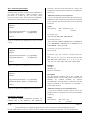
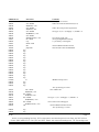
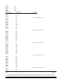
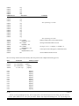
Engineer To Engineer Note
EE-48
Technical Notes on using Analog Devices’ DSP components and development tools
Phone: (800) ANALOG-D, FAX: (781) 461-3010, EMAIL: [email protected], FTP: ftp.analog.com, WEB: www.analog.com/dsp
Copyright 1999, Analog Devices, Inc. All rights reserved. Analog Devices assumes no responsibility for customer product design or the use or application of customers’ products
or for any infringements of patents or rights of others which may result from Analog Devices assistance. All trademarks and logos are property of their respective holders.
Information furnished by Analog Devices Applications and Development Tools Engineers is believed to be accurate and reliable, however no responsibility is assumed by Analog
Devices regarding the technical accuracy of the content provided in all Analog Devices’ Engineer-to-Engineer Notes.
Converting Legacy 21xx Systems
To A 218x System Design
Last Modified: 3/31/99
Introduction
This EE-Note will explain how to convert an existing 21xx
family processor design to a 218x compliant design. The
main differences are with the system builder and
architecture files, the prom splitter, and the actual booting
process of the DSP. Some example code will be shown for
both the legacy 21xx systems and for the updated 218x
system, as well as an example of how the prom splitter
utility (spl21.exe) is utilized to generate a bootable image
for a 218x system. The examples included in this
application note are built using version 6.1 of the 2100
family development tools, which currently is the latest
version.
The System Builder
The system builder (as we all know) is where we define the
memory map for our processor. An important fact to point
out at this time, is that the system builder only knows
about a maximum of 16k words of PM and DM, since the
processor is limited to 14 bits of internal addressing in the
DAG registers.
So, for a 21xx system, you would declare both your
internal and external memory in the *.sys file. For a 218x
system, the *.sys file declares internal memory locations
only; the external memory locations are not declared here.
The use of hardware memory overlays on the 218x
processors is utilized during runtime only. (Currently, the
2100 family development tools work with a maximum of 16k
words of declared PM and DM memory.)
For a 218x system, the development tools do not require
the declaration of EPROM boot pages in the system files
and assembly source. This is contrary to the 21xx designs,
in which it was necessary to define your boot segments in
the source and system files to generate a bootable image
file.
Figure 1 shows an example 2111 system file that declares
2k words of PM memory and 1k words of DM, and a boot
page, which contains 2k bytes of information. Figure 2
shows an example 2187L system file. Note that although
the 2187L has 32k words of internal PM and DM
respectively, only 16k words of each is declared in this
system file. The additional on-chip memory is located in
overlays, which will be explained later in this application
note. For more information on hardware overlays, please
refer to the appropriate 218x datasheet.
.system
Example_2111_System_File;
.adsp2111;
.mmap0;
.seg/pm/ram/code/data/abs=0
int_pm[0x800];
.seg/pm/ram/code/data/abs=0x800 ext_pm[0x37ff];
.seg/dm/ram/data/abs=0x3800
.seg/dm/ram/data/abs=0
int_dm[0x3ff];
ext_dm[0x3800];
.seg/rom/boot=0
.port/dm/abs=0x0400
.port/dm/abs=0x0401
boot0[2048];
a_d_sample_in;
a_d_sample_out;
.endsys;
Figure 1: Example 2111 system file
.system
.adsp2181;
.mmap0;
Example_2187L_System_File;
.seg/pm/ram/code/data/abs=0
int_pm[0x2000];
.seg/pm/ram/code/data/abs=0x2000 ovl_pm[0x2000];
.seg/dm/ram/data/abs=0
.seg/dm/ram/data/abs=0x2000
.endsys;
ovl_dm[0x2000];
int_dm[0x1FE0];
a
{System File Excerpt}
.port/dm/abs=0x0400
Figure 2: Example 2187L system file
For the 2187L system example, please note the omission of
the boot page declarations, “.port” declarations, and the
omission of the upper 32 DM memory locations
(DM0x3fe0-0x3fff) for the memory-mapped control
registers. For more information on these registers, please
refer to the 2100 family user’s manual. We’ll discuss the
negation of the .port directive in a 218x system design later
in this application note.
a_d_sample_in;
{Assembly File Excerpt}
ax0=dm(a_d_sample_in);
Figure 3: 2111’s use of “.port” declaration
{218x Assembly File Excerpt}
.const a_d_sample_in=0x400;
.
.
ax0=io(a_d_sample_in);
Assembly Source Changes
Figure 4: 218x use of memory mapped I/O
Now that you’ve seen the differences in the system
builder, let’s delve further into this and look at the
changes in the assembly source code for a 218x system.
The main differences here are that again, boot pages need
not be declared for a 218x system design
Please note the omission of any “.port” references in the
218x system file. The development tools will generate an
error message when trying to generate a build with “.port”
declarations in a 218x system file. For more information on
the I/O assembly instruction, please refer to page 15-74 of
the 2100 family user’s manual, third edition, or the
appropriate adsp218x datasheet.
Let’s start off with the “.module” declaration, which
signifies the beginning of an assembly file. Here is a listing
for a 2111 assembly source file:
.module/ram/abs=0/boot=0
.module/ram/abs=0/boot=0
Example_2111_Program;
Example_2111_Program;
Here, we notice the inclusion of the boot page qualifier.
Since the 2100 family tools do not use boot pages for a
218x system, we can easily see the changes needed:
.module/ram/abs=0
Example_2187L_Program;
.module/ram/abs=0
Example_2187L_Program;
Memory Mapped I/O Ports
The 218x family processors use a different scheme for
defining memory mapped I/O than the rest of the 21xx
family processors. The addition of the I/O memory space,
with its 2048 memory locations, allows for the mapping of
multiple memory-mapped devices (with different access
speeds) instead of mapping the I/O device using external
data memory. This scheme allows you to use the full 16k
words of on-chip PM and DM and still have the additional
2k locations of 16-bit I/O memory.
For example, here’s an excerpt from our 2111 system and
source files;
EE-48
ADSP-218x Memory Variants
Since the system builder is ignorant to any of the 218x
memory variant processors, we need to “trick” the tools to
work for us when dealing with these processors. Here is a
listing of all of the 218x processors currently available:
Figure 5: Listing of 218x Memory Variant Processors
Processor
adsp2181
adsp2183
adsp2184
adsp2184L
adsp2185
adsp2185L
adsp2186
adsp2186L
adsp2187L
adsp2189M
Memory (PM/DM)
16k/16k
16k/16k
4k/4k
4k/4k
16k/16k
16k/16k
8k/8k
8k/8k
32k/32k
32k/48k
#Pins Volts
128
5v
128
3.3v
100
5v
100
3.3v
100
5v
100
3.3v
100
5v
100
3.3v
100
3.3v
100
2.5/3.3v*
Basically, all we need to do in our system file is to declare
the appropriate memory segments for our specific
processor, while still using the “.adsp2181;” directive. For
Page 2
Technical Notes on using Analog Devices’ DSP components and development tools
Phone: (800) ANALOG-D, FAX: (781) 461-3010, EMAIL: [email protected], FTP: ftp.analog.com
example, let’s define a system file for a 2186 processor,
which has 8k words of internal PM and DM respectively.
.system Example_2186_System_file;
.adsp2181;
.mmap0;
.seg/pm/ram/code/data/abs=0x0000
int_pm[0x2000];
.seg/dm/ram/data/abs=0x2000
int_dm[0x1fe0];
.endsys;
Again we see that there are no memory declarations for
the external overlay memory that is supported by the 218x
processors. The system file should only contain
declarations for on-chip memory; no external memory
should be declared. (Please note here that the “memory
variant” directive, MV, is not supported by the v6.1
development tools. When using a 2181 memory variant
processor, simply use the “.adsp2181;” qualifier.)
This is contrary to the other 21xx processors, because
these processors contained up to 2k words of on-chip
memory. This allowed the addressing capability of the
DAG registers to access internal and external memory as a
“flat” memory model., meaning no memory overlays were
needed to access the additional memory with only 14-bits
of addressing capability. (Remember, 214=16,384 or 16k.)
For more information on memory overlays, please refer to
sections 10.6.1 and 10.6.2 of the 2100 family user’s manual,
third edition.
The PROM Splitter Utility
The latest PROM splitter for the 2100 family development
tools (v6.1) includes what is called a loader, which is a 32word kernel that gets booted initially into the DSP. To
configure a 218x DSP for EPROM boot mode, the DSP’s
MMAP and BMODE pins should be set to zero for the
2181/3 processors, and the MODEA and MODEB pins
should be set to zero for the 2184/5/6/7/9 processors. (For
more information on the configuration of these pins,
please refer to the appropriate processor data sheet.)
is a listing of the complete 113-word loader. If there is no
PM or DM code for a particular page, the 9-word loader
code for that specific page is replaced with NOP
instructions. The loader then initializes data memory by
loading the high-order byte (of the 16-bit DM word) first,
then the low-order byte is loaded. For program memory
initialization, the DSP loads PM memory in the following
order, high-byte, middle-byte, low-byte. Included in the
appendix of this engineer’s note will be an example output
of the PROM splitter highlighting the format of the loader
routine.
32-word loader code
9-word loader code for DM page 0
9-word loader code for DM page 1
9-word loader code for DM page 2
9-word loader code for PM page 5
9-word loader code for PM page 4
9-word loader code for PM page 3
9-word loader code for PM page 2
9-word loader code for PM page 1
9-word loader code for PM page 0
Again, this feature is different from the rest of the 21xx
family, where you had to explicitly define which boot page
your code or data segment resided in your source code.
To generate an EPROM image file from your executable,
invoke the PROM splitter utility with the following
command line switches:
spl21 input_file output_file –2181 -loader
Here, the file named input_file is the name of your
executable file (*.exe) and the output_file is the name of
the output file generated by the splitter utility, with a .bnm
prefix. For example, the following command line will
generate an EPROM image named fft_boot.bnm from the
executable file fft.exe;
Spl21 fft fft_boot –2181 -loader
After reset, the 218x processor is configured by default to
load in the first 96 bytes from the EPROM (which
corresponds to the first 32 program memory locations)
which is the loader kernel. This loader kernel configures
the appropriate BDMA registers to initialize all of the onchip memory locations used by your program.
The loader kernel performs the memory initialization by
loading in 81 program memory words that contain
initialization code for each of the 9 “page” loaders. Below
EE-48
The inclusion of the –2181 and –loader switches instructs
the PROM splitter utility to generate a 218x “friendly”
output file, which works in conjunction with the booting
process of the 218x processor. (There is also support for
the –loader switch for the rest of the 2100 family
processors. Please refer to the development tools release
notes for more information.)
Page 3
Technical Notes on using Analog Devices’ DSP components and development tools
Phone: (800) ANALOG-D, FAX: (781) 461-3010, EMAIL: [email protected], FTP: ftp.analog.com
More Architecture File Examples
Included below are some architecture file definitions for
the various 218x memory variant processors. These
processors are broken up into two main groups;
processors having at least 16k words of on-chip memory,
and processors with less than 16k words of memory.
.system
.adsp2181;
.mmap0;
Example_218x_System_File;
int_pm[0x4000];
int_dm[0x3fe0];
.endsys;
Figure 6: Architecture file definition for 2181/3/5/7L/9M
systems
Example_2186_System_File;
.seg/pm/ram/code/data/abs=0
.seg/pm/ram/data/abs=0
int_pm[0x2000];
int_dm[0x1fe0];
.endsys;
Figure 7: Architecture file definition for a 2186 system
.system
.adsp2181;
.mmap0;
Additional Constants for ALU Operations
A new set of numerical constants may be used in all nonmultifunction ALU operations (except DIVS) using both X
and Y operands. The instruction source code is specified
as follows:
Syntax:
[IF condition]
.seg/pm/ram/code/data/abs=0
.seg/pm/ram/data/abs=0
.system
.adsp2181;
.mmap0;
processors. The term “base instruction set” refers to the
computations and instructions available on all ADSP-21xx
processors.
| AR | = xop function | yop
|
| AF |
| constant |
Permissible xops:
AX0, AX1, AR, MR0, MR1, MR2, SR0, SR1
Permissible functions:
ADD, ADD with CARRY, SUBTRACT X-Y, SUBTRACT
X–Y with BORROW, SUBTRACT Y–X, SUBTRACT Y–X
with BORROW, AND, OR, XOR
Permissible yops (base instruction set)
AY0, AY1, AF
Permissible yops and constants (extended instruction
set)
AY0, AY1, AF, 0, 1, 2, 4, 8, 16, 32, 64, 128, 256, 512, 1024,
2048, 4096, 8192, 16384, 32767, -2, -3, -5, -9, -17, -33, -65,
-129, -257, -513, -1025, -2049, -4097, -8193, -16385, -32768
Examples:
AR=AR+1;
AR=MR1 - 33;
IF GT AF=AX1 OR 16;
Example_2184_System_File;
.seg/pm/ram/code/data/abs=0
.seg/pm/ram/data/abs=0x2000
int_pm[0x1000];
int_dm[0x1000];
.endsys;
Figure 8: Architecture file definition for a 2184 system
Description:
Test the optional condition and, if true, perform the
specified function. If false, then perform a no-operation.
Omitting the condition performs the function
unconditionally. The operands are contained in the data
registers specified in the instruction, or optionally a
constant may be used.
Additional Constants for ALU PASS Operation
A new set of numerical constants may be used in the
PASS instruction. The instruction source code is specified
as follows:
Extended ALU Operations
The following extended computation operations are
available only on the ADSP-2171 and ADSP-2181
EE-48
Syntax:
[IF condition]
| AR | = pass | yop
|
AF
| constant |
Page 4
Technical Notes on using Analog Devices’ DSP components and development tools
Phone: (800) ANALOG-D, FAX: (781) 461-3010, EMAIL: [email protected], FTP: ftp.analog.com
| AF | | SETBIT n of xop; |
| CLBIT n of xop; |
| TGBIT n of xop;
|
Permissible yops (base instruction set)
AY0, AY1, AF
Permissible xops
AX0, AX1, AR, MR0, MR1, MR2, SR0, SR1
Permissible yops and constants (extended instruction
set)
AY0, AY1, AF, 0, 1, 2, 3, 4, 5, 7, 8, 9, 15, 16, 17, 31, 32, 33,
63, 64, 65, 127, 128, 129, 255, 256, 257, 511, 512, 513, 1023,
1024, 1025, 2047, 2048, 2049, 4095, 4096, 4097, 8191, 8192,
8193, 16383, 16384, 16385, 32766, 32767, -1, -2, -3, -4, -5, -6,
-8, -9, -10, -16, -17, -18, -32, -33, -34, -64, -65, -66, -128, -129,
-130, -256, -257, -258, -512, -513, -514, -1024, -1025, -1026,
-2048, -2049, -2050, -4096, -4097, -4098, -8192, -8193, -8194,
-16384, -16385, -16386, -32767, -32768
Example:
IF GE AR = PASS AY0;
IF EQ AF = PASS -1025;
Description:
Test the optional condition and, if true, pass the source
operand unmodified through the ALU block and store in
the destination location. If the condition is not true,
perform a no-operation. Omitting the condition performs
the pass unconditionally. The source operand is contained
in the data registers specified in the instruction or optional
constant.
The PASS instruction performs the transfer to the AR
register and affect the status flag; this instruction is
different from a register move operation which does not
affect any status flags. PASS 0 is one method of clearing
AR. PASS 0 can also be combined in a multifunction
instruction in conjunction with memory reads and writes
to clear AR.
Note:
The ALU status flags (in the ASTAT register) are not
defined for the execution of this instruction when using
the constant values other than 0, 1, and -1.
Permissible n Values (0 = LSB)
0, 1, 2, 3, 4, 5, 6, 7, 8, 9, 10, 11, 12, 13, 14, 15
Examples:
AF=TSTBIT 5 of AR;
IF NE JUMP SET; /* JUMP TO SET IF BIT IS SET */
Definitions of Operations
TSTBIT is an AND operation with a 1 in the selected bit
SETBIT is an OR operation with a 1 in the selected bit
CLBIT is an AND operation with a 0 in the selected bit
TGBIT is an XOR operation with a 1 in the selected bit
Result-Free ALU Operations
The result-free ALU operations allow the generation of
condition flags based on an ALU operation but discard
the result. The source code for the instruction is specified
as follows:
Syntax:
NONE = <ALU>;
Where <ALU> is any unconditional ALU operation of the
21xx base instruction set (except DIVS or DIVQ). (Note
that the additional constant ALU operations of the 21xx
extended instruction set are not allowed.)
Examples:
NONE = AX0 – AY0;
NONE = PASS SR0;
Description:
Perform the designated ALU operation, set the condition
flags, then discard the result value. This allows the testing
of register values without disturbing the AR or AF register
values.
ALU Bit Operations
The additional constants for ALU operations allow you to
code bit test, set, clear, and toggle operations through
careful choice of the constant and ALU function. For
streamlined programming, the source code for these
operations can also be specified as:
Syntax:
EE-48
[IF condition] | AR | = | TSTBIT n of xop; |
Page 5
Technical Notes on using Analog Devices’ DSP components and development tools
Phone: (800) ANALOG-D, FAX: (781) 461-3010, EMAIL: [email protected], FTP: ftp.analog.com
Appendix A:
Example Source File Listing
Here is a simple assembly program that adds two numbers stored in data memory:
.module example1;
.var/dm/ram/abs=0x10 x;
.init x: 0x7;
.var/dm/ram/abs=0x11 y;
.init y: 0x21;
start:
ax0 = dm(x);
ay0 = dm(y);
ar = ax0 + ay0;
.endmod;
After the program is assembled and linked, the .BNM file generated in Intel S Record format by executing the PROM splitter
with the -2181 and -loader switches is shown below:
S22500000040060093FE2040020093FE1040000093FE3040087093FE403C008C0000003C0083EF
S22500002102800018020F0000000000000000000000000000000000000000000000000000000E
S2250000420000000000000000000000000000000000000A001F000000000000000000401F50C0
S22500006393FE2040010093FE1040001093FE3040002093FE4002800000000000000000000020
S22500008400000000000000000000000000000000000000000000000000000000000000000056
S2250000A500000000000000000000000000000000000000000000000000000000000000000035
S2250000C600000000000000000000000000000000000000000000000000000000000000000014
S2250000E7000000000000000000000000000000000000000000000000000000000000000000F3
S225000108000000000000000000000000000000000000000000000000000000000000000000D1
S225000129000000000000000000000000000000401F9093FE2040000093FE1040008093FE30AE
S22500014A40003093FE40028000000000000000000000000000000000000000000000000000CC
S22500016B0000000000000000000000000000000000000000000000000000000000000000006E
S22500018C0000000000000000000000000000000000000000000000000000000000000000004D
S2250001AD0000000000000000000000000000000000000000000000000000000000000000002C
S2250001CE0000000000000000000000000000000000000000000000000000000000000000000B
S2250001EF0000000000000007002180010080011422600FFFFFFFFFFFFFFFFFFFFFFFFFFFFF29
S9030000FC
The program and data words are shown in bold; the other characters are Intel S Record-related. In the following listing, the
program and data words are disassembled and described (please note the inclusion of only 2 boot pages; 1 PM page and 1
DM page):
EE-48
Page 6
Technical Notes on using Analog Devices’ DSP components and development tools
Phone: (800) ANALOG-D, FAX: (781) 461-3010, EMAIL: [email protected], FTP: ftp.analog.com
PM/DM Word
Instruction
400600
93FE20
400200
93FE10
400000
93FE30
400870
93FE40
3c008c
000000
3c0083
028000
18020F
000000
000000
000000
000000
000000
000000
000000
000000
000000
000000
000000
000000
000000
000000
000000
0A001F
000000
000000
000000
ax0 = 0x0060
dm(BEAD) = ax0
ax0 = 0x0020
dm(BIAD) = ax0
ax0 = 0x0000
dm(BDMAC) = ax0
ax0 = 0x0087
dm(BWCOUNT) = ax0
ifc = 0x008
nop
imask = 0x08
idle
jump 0x20
nop
nop
nop
nop
nop
nop
nop
nop
nop
nop
nop
nop
nop
nop
nop
rti
nop
nop
nop
401F50
93FE20
400100
93FE10
400010
93FE30
400020
93FE40
028000
ax0 = 0x01f5
dm(BEAD) = ax0
ax0 = 0x0010
dm(BIAD) = ax0
ax0 = 0x0001
dm(BDMAC) = ax0
ax0 = 0x0002
dm(BWCOUNT) = ax0
idle
000000
000000
nop
nop
EE-48
Comments
Start of 32 word loader
load in 96 words of loader kernel (32 x 3)
load in the code past the original boot
set btype = 0, bcr = 0, bmpage = 0, and bdir = 0
size of byte loader code
clears pending BDMA interrupt
1 cycle latency in setting IFC
wait for BDMA transfer to finish
start of loader code is at PM0x0020
BDMA interrupt vector
Start of DM Page 0 Loader
start of DM code
set btype = 1, bcr = 0, bmpage = 0, and bdir = 0
count of dm code on bm page 0
wait for BDMA transfer to finish
Start of DM Page 1 Loader
Page 7
Notes on using Analog Devices’ DSP components and development tools from the DSP Division
Phone: (800) ANALOG-D, FAX: (781) 461-3010, EMAIL: [email protected], FTP: ftp.analog.com
000000
000000
000000
000000
000000
PM/DM Word
nop
nop
nop
nop
nop
Instruction
000000
000000
nop
nop
000000
000000
000000
000000
000000
000000
000000
000000
000000
nop
nop
nop
nop
nop
nop
nop
nop
nop
000000
000000
000000
000000
000000
000000
000000
000000
000000
nop
nop
nop
nop
nop
nop
nop
nop
nop
000000
000000
000000
000000
000000
000000
000000
000000
000000
nop
nop
nop
nop
nop
nop
nop
nop
nop
000000
000000
000000
000000
000000
000000
000000
000000
000000
nop
nop
nop
nop
nop
nop
nop
nop
nop
000000
000000
nop
nop
Comments
Start of DM Page 2 Loader
Start of PM Page 5 Loader
Start of PM Page 4 Loader
Start of PM Page 3 Loader
Start of PM Page 2 Loader
EE-48
Page 8
Notes on using Analog Devices’ DSP components and development tools from the DSP Division
Phone: (800) ANALOG-D, FAX: (781) 461-3010, EMAIL: [email protected], FTP: ftp.analog.com
000000
000000
000000
000000
000000
PM/DM Word
nop
nop
nop
nop
nop
Instruction
000000
000000
nop
nop
000000
000000
000000
000000
000000
000000
000000
000000
000000
nop
nop
nop
nop
nop
nop
nop
nop
nop
401F90
93FE20
400000
93FE10
400080
93FE30
400030
93FE40
028000
ax0 = 0x01f9
dm(BEAD) = ax0
ax0 = 0x0000
dm(BIAD) = ax0
ax0 = 0x0008
dm(BDMAC) = ax0
ax0 = 0x0003
dm(BWCOUNT) = ax0
idle
Comments
Start of PM Page 1 Loader
Start of PM Page 0 Loader
address of PM code in external byte memory
starting internal PM address of code
set btype = 0, bcr = 1, bmpage = 0, and bdir = 0
count of pm code on bm page 0 (3-PM instructions)
wait for BDMA transfer to finish
Here is a listing of the actual code in memory after the processor has completed the booting process;
Data
800100
800114
22600F
uuuu
uuuu
uuuu
uuuu
uuuu
uuuu
uuuu
uuuu
uuuu
uuuu
uuuu
uuuu
EE-48
Instruction
ax0 = dm (0x0010)
ay0 = dm (0x0011)
ar = ax0 + ay0
Memory Location
pm[0x0]
pm[0x1]
pm[0x2]
dm[0x0]
dm[0x1]
dm[0x2]
dm[0x3]
dm[0x4]
dm[0x5]
dm[0x6]
dm[0x7]
dm[0x8]
dm[0x9]
dm[0xa]
dm[0xb]
Page 9
Notes on using Analog Devices’ DSP components and development tools from the DSP Division
Phone: (800) ANALOG-D, FAX: (781) 461-3010, EMAIL: [email protected], FTP: ftp.analog.com
uuuu
uuuu
uuuu
uuuu
0007
0021
EE-48
dm[0xc]
dm[0xd]
dm[0xe]
dm[0xf]
dm[0x10]
dm[0x11]
Page 10
Notes on using Analog Devices’ DSP components and development tools from the DSP Division
Phone: (800) ANALOG-D, FAX: (781) 461-3010, EMAIL: [email protected], FTP: ftp.analog.com