1
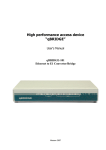
HCT-BERT/C(E1)
E1/Datacom BER Tester
LEGAL
The information in this publication has been carefully checked and is believed to be
entirely accurate at the time of publication. CTC Union Technologies assumes no
responsibility, however, for possible errors or omissions, or for any consequences
resulting from the use of the information contained herein. CTC Union Technologies
reserves the right to make changes in its products or product specifications with the
intent to improve function or design at any time and without notice and is not
required to update this documentation to reflect such changes.
CTC Union Technologies makes no warranty, representation, or guarantee regarding
the suitability of its products for any particular purpose, nor does CTC Union
assume any liability arising out of the application or use of any product and
specifically disclaims any and all liability, including without limitation any
consequential or incidental damages.
CTC Union products are not designed, intended, or authorized for use in systems or
applications intended to support or sustain life, or for any other application in which
the failure of the product could create a situation where personal injury or death may
occur. Should the Buyer purchase or use a CTC Union product for any such
unintended or unauthorized application, the Buyer shall indemnify and hold CTC
Union Technologies and its officers, employees, subsidiaries, affiliates, and
distributors harmless against all claims, costs, damages, expenses, and reasonable
attorney fees arising out of, either directly or indirectly, any claim of personal injury
or death that may be associated with such unintended or unauthorized use, even if
such claim alleges that CTC Union Technologies was negligent regarding the design
or manufacture of said product.
TRADEMARKS
Microsoft is a registered trademark of Microsoft Corp.
CTC Union Technologies Co., Ltd.
Far Eastern Vienna Technology Center (Neihu Technology Park)
8F, No. 60, Zhouzi St.
Neihu, Taipei, 114
Taiwan
Phone: +886-2-2659-1021
FAX: +886-2-2799-1355
MHCT-BERT/C
E1 / Data Communications Bit Error Rate Tester
User Manual
Version 1.2 December 2010
This manual supports the following models:
HCT-BERT/C
HCT-BERT/E1
Note: Model HCT-BERT/E1 supports E1 testing only (no Data Communications).
This document is the current official release manual. Please check CTC Union's
website for any updated manual or contact us by E-mail at [email protected]. Please
address any comments for improving this manual or to point out omissions or errors
to [email protected]. Thank you.
©2009-2010 CTC Union Technologies Co., Ltd.
All Rights Reserved
Th
t t
f thi d
t
bj t t
h
ith t
i
ti
Contents
Chapter 1 HCT-BERT/C(E1) Overview ...................................................................7
1.1 Introduction ....................................................................................................7
1.2 Function..........................................................................................................7
1.3 Overall Functions and Specifications ........................................................8
1.4 LED Status Display ....................................................................................11
1.5 Interface Panel ............................................................................................14
Chapter 2 E1 Test .....................................................................................................16
2.1 Parameter Setup .............................................................................................16
2.2 Parameter Explanations .................................................................................18
2.3 Time Slot Setup..............................................................................................21
Chapter 3 Result Analysis........................................................................................24
3.1 Introduction....................................................................................................24
Chapter 4 Data Test and Result Analysis .............................................................30
4.1 High-speed Data Test ................................................................................30
4.2 Low-speed Data Test.................................................................................34
Chapter 5 Document Management ........................................................................38
5.1 Introduction ..................................................................................................38
5.2 Configuration File........................................................................................38
5.3 Result File ....................................................................................................39
Chapter 6 Advanced Options ..................................................................................40
6.1 Introduction ..................................................................................................40
6.2 E1 Frequency Test .....................................................................................40
6.3 Pattern Editor ..............................................................................................41
6.4 Round Trip Delay........................................................................................41
6.5 Signal Bit Test .............................................................................................43
6.6 Signal Bit Editor ..........................................................................................45
Chapter 7 Device.......................................................................................................49
7.1 Introduction ..................................................................................................49
7.2 Version Information ....................................................................................49
7.3 Factory Default............................................................................................50
7.4 Language Select.........................................................................................50
7.5 Sound Setup................................................................................................51
7.6 Miscellaneous Setup ..................................................................................52
Chapter 8 Terminal ...................................................................................................56
Appendices: ..............................................................................................................57
HCT-BERT/C(E1)
Overview
Chapter 1 HCT-BERT/C(E1) Overview
1.1 Introduction
HCT-BERT/C(E1), a hand-held E1 data error-testing instrument with a
true-color screen and graphic and full-Chinese operating interface is used
in field maintenance and analysis of E1/G.703 line and error test of data
communicationg (V.35, V.24/RS232, RS449, RS530, X.21) (Only
HCT-BERT/C support). It features all-around functions and convenient
operations, and can analyze & display test results in conformity with
international standard such as G.821, G.826 and M.2100 and be able to
store and carry out a statistics & analysis on data results according to the
requirements of users as well, and is ideal tool in line quality measurement.
1.2 Function
z
True-color screen, graphic & full English/Chinese operating interface
z
More than one type of E1 error analysis, including E1 frame, pattern,
CRC and BPV analysis
z
Error performance analysis (G.821, G.826, M.2100)
z
E1 signal frequency offset test
z
Setup of various time slots of E1 line available (FAS, CAS)
z
Diversion & insertion of time slots in E1 channel (N × 64Kdata) available.
z
ABCD bit setting and display of CAS signaling.
z
Sa bit setup and display of 0 time slot.
z
Error test of data port (interface mode: V.35, V.24/RS232, RS449,
RS530, X.21).
z
OOS
(Out-of-Service)
&
ISM
(In-Service-Measurement)
error
performance analysis.
z
Storage of 100 config & test result documents available, which user can
store or call out.
z
Visual display in histogram.
z
More than one output modes of test results: internal storage result, LCD
screen display, and LPT print.
z
Embedded large-capacity rechargeable lithium battery, portable for field
use.
7
HCT-BERT/C(E1)
Overview
1.3 Overall Functions and Specifications
1.3.1 E1 Specifications:
1). E1 Receiving Interface
z Line code: HDB3/AMI
z Pulse characteristics: in conformity with ITU G.703
z Jitter tolerance: in conformity with ITU G.823
z Input port Type:
Coaxial twin: BNC (non-balance)
Symmetrical twin: RJ45 (balance)
z Input mode:
Terminal mode:
Coaxial Pair Impendance: 75ohm (unbalanced)
Symmetrical Pair Impendance: 120ohm (balanced)
Bridging mode:
Impedance: > 1000 ohm
2). E1 Transmission Interface
z Line code: HDB3/AMI
z Pulse characteristics: in conformity with ITU G.703
z Pulse amplitude: Nominal value of 2.37V for 75ohm of coaxial pair
Nominal value of 3.00V for 120 ohm of symmetrical pair
z Zero amplitude: ± 0.1 V at max
z Jitter tolerance: in conformity with ITU G.823
z Output port model:
Coaxial Pair: BNC (non-balance)
Symmetrical Pair: RJ45 (balance)
z Source of clock transmission:
Internal Timing: 2.048 MHz ±50ppm, ±100ppm.
External Timing: take clock from external clock interface
Recovery Timing: take clock from receiving terminal
3). E1 Frame Format
z PCM31
z PCM31+CRC
z PCM30
z PCM30+CRC
z Unframed
z Automatic detection
8
HCT-BERT/C(E1)
Overview
1.3.2 Error Rate Test (BERT Test):
1). BERT Pattern (Patterns)
511, 2047, 2E15-1, 2E15-1 (reverse), 2E20-1, 2E20-1 (reverse), QRSS,
2E23-1, 2E23-1 (reverse), all 1, all 0, alternate, 1100, 3 IN 24, 1 IN 16, 1 IN 8,
1 IN 4, User Programmble1, 2, 3, LIVE
2). BERT Display Format
z Error counting
z Alarm counting
z ITU G.821
z ITU G.826
z M.2100
z Histogram
3). BERT Transmission Error Rate
z Force Single Error
z Force 10-3-10-7 Error Rate
4). Quality Analysis:
z Receiving seconds
z Error seconds
z Alarm seconds
z Error Free seconds
z Error rate
z Available seconds
z Serious error seconds
z G.821 error seconds
z G.826 error seconds
z Unavailable seconds
5). Data Port BERT Test (Only HCT-BERT/C support)
z Data rate of the multiple of 64Kbps: N*64Kbps (N=1~36)
1.3.3 Other Functions:
1). Color Display Screen
z Character/graphic mode
2). Test Results Report
z 100 pieces of test results at max available in storage
z Direct display on LCD screen
z Print via printer port available
3). Portable for Field Use
4). Modular Design for Easy Update
9
HCT-BERT/C(E1)
Overview
5). Battery Supply: 4 hours
6). Temperature Range: 0 °C-50 °C (operating temperature)
-20 °C-60 °C (storage temperature)
7). Humidity: up to 95% without condensing
8). Power supply source: AC-230V / DC9V/2000mA power Switch
Adapter
9). Dimensions
178.5mm (L) × 133.5 mm (L) × 68 mm (H)
10). Weight
Less than 0.8kg (net weight)
1.3.4 Interface profile:
Figure 1-1 HCT-BERT/C(E1) Profile(HCT-BERT/E1 NO Data port)
z BNC * 2:
E1 transmission and receiving (Unbalanced)
z BNC:
External clock
z RJ45:
E1 transmission and receiving (balanced)
z HDB26 (female socket): data port (RS232/V.24, V.35, V.36, X.21, RS-449,
EIA-530 interface)
z HDB26 (female socket): printer port
z USB:
communication port between instrument and PC
z Power switch:
power on/off
z Power socket: DC-9V
10
HCT-BERT/C(E1)
Overview
1.4 LED Status Display
HCT-BERT/C LED is on the left side of front panel and displays as follows:
Digital signal
Name
Color
DTE
GREEN
DCE
GREEN
DATA PORT
GREEN
TD
RD
DCD
RTS
CTS
DTR
DSR
TC
RC
XTC
BIT ERR
LOP
GREEN
GREEN
GREEN
GREEN
GREEN
GREEN
GREEN
GREEN
GREEN
GREEN
RED
RED
Color
GREEN
GREEN
GREEN
RED
RED
RED
RED
RED
RED
RED
RED
RED
RED
RED
RED
RED
E1 signal
Name
Terminal
Bridge
E1
LOS
AIS
LOF
LOMF
LOCRC
RAI
MRAI
LOP
CODE ERR
FAS ERR
BIT ERR
CRC ERR
E BIT ERR
HCT-BERT/E1 LED is on the left side of front panel and displays as follows:
Color
GREEN
GREEN
GREEN
RED
RED
RED
RED
RED
RED
RED
RED
RED
RED
RED
RED
RED
E1 signal
Name
Terminal
Bridge
E1
LOS
AIS
LOF
LOMF
LOCRC
RAI
MRAI
LOP
CODE ERR
FAS ERR
BIT ERR
CRC ERR
E BIT ERR
11
HCT-BERT/C(E1)
Overview
Details of LED indicators are as follows:
1) Digital Signal Display
DTE:
Green LED means that the data port currently works in DTE mode.
DCE:
Green LED means that the data port currently works in DCE mode.
DATA PORT:
When data port is currently engaged, LED displays green.
TD:
Green LED means some data is under transmission.
RD:
Green LED means some data is being received.
DCD:
Green LED means Data Carrier Detect.
RTS:
Green LED means Request to send.
CTS:
Green LED means Clear to send.
DTR:
Green LED means Data terminal ready.
DSR:
Green LED means Data set ready.
TC:
Green LED means Transmit Clock.
RC:
Green LED means Receive clock.
XTC:
Green LED means DTE Transmit clock.
BIT ERR:
Red LED means bit error detected during the test of testing pattern.
LOP:
Red LED means Loss of Pattern synchronization.
2) E1 Signal Display
Terminal (terminal mode):
Green LED means that HCT-BERT/C E1 reception is set up in terminal
mode and the impedance may be E1 75 ohm or E1 120ohm.
Bridge (bridging mode):
Green LED means that HCT-BERT/C E1 reception is set up in
high-impedance bridging mode.
12
HCT-BERT/C(E1)
Overview
E1:
Green LED means that HCT-BERT/C works in E1 test mode.
LOS: (Loss of Signal):
Red LED means that the signal received via E1 receiving port is too
weak and is equal to or less than 35db, with detection time: 10≤code element
quantity ≤255.
AIS: (Receive Alarm Indication Signal, all are the frame of 1)
Red LED means that there is some criteria in ITU G.775 detected and
released by RAIS. In E1 mode, in case that there are two consecutive twin
frames (500us), each 512 bit contains two or less than two 0 and moreover,
FAS alignment doesn’t exist, the light will turn on; and release condition of
RAIS is that in two consecutive twin frames (500us), 512 bit contains three or
more 0 received, or FAS alignment resumes.
LOF:
Red LED means Loss of Frame Alignment
LOMF:
Red LED means Loss of CAS multi-frame alignment
LOCRC:
Red LED means Loss of CRC-4 multi-frame alignment
RAI: (Receive Remote Alarm Indication)
Red LED means that in E1 mode, if in two consecutive NFAS, TS0 bit
3=1, the light will turn on; and if in two consecutive NFAS frames, TS0 bit 3=0,
the light will turn off.
MRAI:
Red LED means Multi-frame Remote Alarm Indication
Multi-frame remote-end alarm indication
LOP:
Red LED means Loss of Pattern synchronization
CODE ERR:
Red LED means HDB3 code alternation-polarity error. We can find out
breakdown point firstly and check if the polarity of breakdown point is altered.
In case of no alternation, coding error should be confirmed.
FAS ERR:
Red LED means error in frame alignment signal (0011011)
BIT ERR:
Red LED means bit error detected in the test of testing pattern.
CRC ERR:
Red LED means that CRC-4 error is calculated
E-BIT ERR:
Red LED means that CRC-4 error occurs to remote and is indicated with
E bit.
13
HCT-BERT/C(E1)
Overview
1.5 Interface Panel
Figure 1-2 Front Panel of HCT-BERT/C(E1)(HCT-BERT/E1 NO Data port)
Description:
TX (BNC):
Unbalance transmission port of E1, and BNC Type
RX (BNC):
Unbalance receiving port of E1, BNC Type
RJ45:
Balance interface of E1 for transmission (TX) and receiving (RX)
G703-CLK (external clock):
Input interface of reference clock of external E1
DATA PORT:
Data port can be set up as RS232/V.24, V.35, V.36, X.21, RS-449 and
EIA-530 communication ports. Accessory connecting cables of the device
can be used for testing data port.
Figure 1-3 Side Panel of HCT-BERT/C(E1)
14
HCT-BERT/C(E1)
Overview
Description:
POWER ON:
Switch of power supply
REMOTE:
It is a communication port between instrument and PC (USB interface).
The user can configure the instrument or update its software in adoption of
PC via USB interface.
DC-9V:
When external power adapter (DC9V/2A adapter) is used, insert the
adapter into the socket for power supply. In case of inadequate electric
energy of battery, please use external power adapter for charging.
CHARGE UP:
It is indicator light of charging. When external power adapter is inserted,
LED turn-on means charging goes on and turn-off means adequate electric
energy of the battery.
Printer (printer):
If accessory printer cable of the device is used, it can be connected to
average printer port.
15
HCT-BERT/C(E1)
E1 Test
Chapter 2 E1 Test
2.1 Parameter Setup
When HCT-BERT/C(E1) is at the main menu, press Õ,Ö cursor keys to
select “E1 Analyzer”. The interface displays various configurations as in
Figure 2-1:
Figure 2-1 Configuration Setup Interface of E1 Analyzer
Four items i.e. ” User File, ”Default “, “Configuration and ” Run Test “ are
included, with meanings as follows:
User File: call a parameter setup file pre-stored in the instrument as in
Figure 2-2. The user can move the cursor by ×, Ø keys and select different
key.
parameter setup files by
Figure 2-2 User File Interface of E1 Test
Default: set up all parameters in E1 test as default values, and
enter ”Parameter setup“ interface rapidly to confirm if default setup
parameters are in conformity with test requirements or modify accordingly.
Configuration: enter ” Configuration interface as in Figure 2-3.
16
HCT-BERT/C(E1)
E1 Test
Figure 2-3 Configuration Interface of E1 Test
There are parameters available for setup in the interface. Move the
cursor by ×, Ø keys, and select relevant items by
key. Popup dialog box
will list out the options for a parameter as in Figure 2-4.
Figure 2-4 Parameter Value Selection Interface of E1 Test
In the interface of Figure 2-4, move the cursor by ×, Ø keys to select
key to confirm. For the meaning of
different parameter options, and use
each parameter, please refer to “2.2 Parameter Explanations”.
Run test: select the instrument, and enter test status. Various parameter
values of the instrument are the options set up last time.
The above is the setup for E1 test of HCT-BERT/C(E1). On the right side
of ” Configuration interface (Figure 2-3), there are four function keys i.e. ”
Mdfy, ”Default “, ”Save “ and ”Test“, which correspond with F1, F2, F3 and F4
keys. Press relevant keys to call corresponding functions rapidly.
Save: in ” Configuration interface, press F3 key, and select ”Save
“ function to save up current parameter setup in a file. In later operation, use
Mdfy function to call corresponding parameter setup as in Figure 2-2.
Select ”Save “ function interface as in Figure 2-5.
17
HCT-BERT/C(E1)
E1 Test
Figure 2-5 Parameter Setup Saving Interface of E1 Test
Move the cursor by Õ, Ö, × & Ø keys to the letter or digit in demand,
and press the key of letter or digit as file name. ” Enter, ” Ecs & “Backspace”
keys on the right side correspond with F1, F2 & F3 keys respectively.
2.2 Parameter Explanations
Valid parameter setups of HCT-BERT/C(E1) and meanings are as
follows:
Parameter
Option
Description
Connection
Type
Terminal
75ohm
120ohm
High
Low
HDB3
Set up HCT-BERT/C(E1) transmitting and receiving ports in
E1 terminal mode.
Set up HCT-BERT/C(E1) in E1 bridge mode. Receiving
terminal impedance ≥1Kohm .
Set up HCT-BERT/C(E1)port impedance as 75ohm.
Set up HCT-BERT/C(E1) port impedance as 120ohm.
Set up the highest receiving sensibility
Set up the lowest receiving sensibility
Set up line coding mode as HDB3.
AMI
Set up line coding mode as AMI.
PCM31
PCM31 mode.
When time slot is set up as FULL, all FAS+ time slots from
TS1-TS31 are set up as being engaged;
When time slot is set up as N*64, time slot is TS that FAS+
sets up as being engaged (other TS set up as being idle).
Note: TS: time slot
PCM30 mode.
When time slot is set up as FULL, the FAS+CAS+time slots
including TS1-TS15 and TS17-TS31 all are set up being
engaged;
When time slot is set up as N*64, FAS+CAS+TS are set up
as being engaged (other TS set up being idle).
PCM31 mode, CRC4 start-up.
When time slot is set up as FULL, FAS time slot TS1-TS31
all are set up being engaged;
When time slot is set up as N*64 时, time slot is TS that
FAS+ sets up being engaged (other TS being idle).
Bridge
Impedance
Sensibility
Code
Framing
PCM30
PCM31+CR
C
18
HCT-BERT/C(E1)
PCM30+CR
C
Non-framing
Automatic
detection
Time slot
setup
Full
N*64
Transmit
clock
E1 Test
PCM30 mode, CRC4 start-up.
When time slot is set up as FULL, FAS+CAS+time slot TS1TS15 and TS17-TS31 all are set up being engaged;
When time slot is set up as N*64, FAS+CAS+ sets up as
engaged TS (other TS being idle).
Non-framing mode. TS0-TS31 all are set up being engaged.
Automatic detection mode. HCT-BERT/C will automatically
identify framing model of E1 interface of terminal according
to the status of current line.
Select according to framing model, and set up all time slots
available as being engaged (see ”framing model”
description).
Select a time slot available, and set up as being engaged or
idle (see ”framing model” description). For detailed setup,
please refer to 3.3 Time Slot Setup.
Recovery
clock
Transmit clock, and take the clock from E1/T1 receiving port
(Recovery), and use it as reference clock.
Internal
clock
Transmit clock, and take the frequency produced by internal
External
clock
Transmit clock, and take clock input via external (reference
50ppm
Transmit clock, and take the frequency produced by internal
quartz vibrator of HCT-BERT/C(E1) i.e. 2048K bps.
clock) port of HCT-BERT/C(E1), and use as reference
clock.
quartz vibrator of HCT-BERT/C(E1) plus a deviant of
50ppm, and use as reference clock.
100ppm
Transmit clock, and take the frequency produced by internal
quartz vibrator of HCT-BERT/C(E1) plus a deviant of
100ppm, and use as reference clock.
-50ppm
Transmit clock, and take the frequency produced by internal
quartz vibrator of HCT-BERT/C(E1) plus a deviant of
-50ppm, and use as reference clock.
-100ppm
Transmit clock, and take the frequency produced by internal
quartz vibrator of HCT-BERT/C(E1) plus a deviant of
-100ppm, and use as reference clock.
Test
pattern
511
Pseudo-random sequence pattern: 2E9-1 (O.153)
2047
Pseudo-random sequence pattern: 2E11-1 (O.152 and
O.153)
2E15-1
Pseudo-random sequence pattern: 2E15-1 (O.151)
2E15-1
(reverse)
Pseudo-random sequence pattern: 2E15-1 (O.151 reverse)
2E20-1
Pseudo-random sequence pattern: 2E20-1 (O.153)
2E20-1
(reverse)
Pseudo-random sequence pattern: 2E20-1 reverse)
QRSS
Pseudo-random sequence pattern: 2E20-1 (O.151 QRSS)
2E23-1
Pseudo-random sequence pattern: 2E23-1 (O.151)
2E23-1
(reverse)
Pseudo-random sequence pattern: 2E23-1 (O.151 reverse)
All 1
Repetitive pattern: all 1 (11111...)
19
HCT-BERT/C(E1)
Test time
Idle code
E1 Test
All 0
Repetitive pattern: all 0 (00000...)
Alternate
Repetitive pattern: alternate 1 & 0 (10101010...)
1100
Repetitive pattern: all 1100
3 IN 24
Repetitive pattern: 3 ”1” in 24 bits
1 IN 16
Repetitive pattern: 1 ”1” in 16 bits
1 IN 8
Repetitive pattern: 1 ”1” in 8 bits
1 IN 4
Repetitive pattern: 1 ”1” in 4 bits
User pattern
1
User programmable pattern 1 with pattern length of 1-32 bit.
For detailed setup, please refer to 5.4 User Programmable
Test Pattern.
User pattern
2
User programmable pattern 2 with pattern length of 1-32 bit.
For detailed setup, please refer to 5.4 User Programmable
Test Pattern.
User pattern
3
User programmable pattern 3 with pattern length of 1-32 bit.
For detailed setup, please refer to 5.4 User Programmable
Test Pattern.
Consecutive
15 minutes
30 minutes
1 hour
24 hours
7E
Execute BERT test all the time
Execute BERT test for 15 minutes
Execute BERT test for 30 minutes
Execute BERT test for one hour
Execute BERT test for one day
The time slot preset as idle will be filled with a hexadecimal
0x7E code during the time slot transmitted.
7F
The time slot preset as idle will be filled with a hexadecimal
0x7E code during the time slot transmitted.
If the clock transmission is set up as ”recovery clock“, the
data received by idle time slot will be used as ”idle code”
and be transmitted via the time slot again.
Pass
After the parameter is set up, carry out ”test“ function. The instrument will
run E1 error analysis function. For detailed operations, see Chapter 6 Error
Analysis Function.
20
HCT-BERT/C(E1)
E1 Test
2.3 Time Slot Setup
When a time slot of HCT-BERT/C(E1) is set up as N*64 as in Figure 2-6,
enter time slot setup interface as in Figure 2-7.
Figure 2-6 Time Slot Setup Interface
Figure 2-7 N*64 Mode Time Slot Setup Interface
In case of framing type of PCM31 or PCM31+CRC, 31 time slots (time
slot 1-31) can be set up. In case of framing type of PCM30 or PCM30+CRC,
30 time slots (time slot 1-15, and time slot 17-31) can be set up. In case of
framing type of Unframe all 32 time slots (time slot 0-31) can be set up as
engaged.
In Figure 2-7 N*64 Mode Time Slot Setup Interface, there are 32 digits
and symbols such as ”*” & “-” on the screen, of which each symbol represents
current setup status of one time slot as follows:
* The time slot is set up as being engaged and can be loaded with data
transmission and receiving.
- The time slot is set up as being idle, and can transmit idle code via
the transmission part.
F The time slot cannot be set up.
Moreover, small check that each represents one time slot displays
current status with color.
Red: the time slot cannot be set up.
21
HCT-BERT/C(E1)
E1 Test
Green: the time slot is set up as being engaged.
Black: the time slot is set up as being idle.
White: the position of time slot where current cursor stays.
In time slot figure, white small check represents the time slot where the
current cursor stays. Press ”ד, ”Ø“, “Õ“ or ”Ö“ key to move the cursor.
Function keys including “Active, ”Idle”, ”All Active & ”All idle” on the right side
correspond with F1, F2, F3 & F4 respectively. The function keys can change
the setup of time slot where current cursor stays, or use/not use all time slots.
Detailed meaning and action of various function keys are as follows:
[F1] Active Set up the time slot as being engaged.
[F2] Idle
Set up the time slot as being idle.
[F3] All Active Set up all time slots as being engaged.
[F4] All idle
Set up all time slots as being idle.
After the status of time slot is changed, use
key for confirming.
2.4 User Programmable Test Pattern
If HCT-BERT/C(E1) stays in the main menu, press Õ & Ö keys of the
cursor to select “Advanced options”. The menu will display advanced
configurations for selection as in Figure 2-8:
Figure 2-8 Advanced Options Setup Interface
Use × & Ø keys to move the cursor to ”Pattern Editor, and press
key
to enter the editing interface of user test pattern as in Figure 2-9.
For error test analysis, three user-programming patterns can be set up.
The repetitive character length in user programmable test pattern is 32
bits. The length of current test pattern displays on each user test pattern.
22
HCT-BERT/C(E1)
E1 Test
Figure 2-9 User Test Pattern Editing Interface
The function key “1”, ”0”, “-” and ”Save “ on the right side correspond with
the key F1, F2, F3 & F4 respectively. The explanation of each function key is
as follows:
[F1] 1
Set up the bit as ”1”.
[F2] 0
Set up the bit as ”0”.
[F3] Delete the bit. When the cursor stays on the final bit of the
character, press ”-” key to delete the whole bit and cut off the length of the
whole character by 1 accordingly.
[F4] Save Save up current user pattern setup.
23
HCT-BERT/C(E1)
Result Analysis
Chapter 3 Result Analysis
3.1 Introduction
When HCT-BERT/C(E1) is at the main menu, select “Start test” to enter
BERT test and analysis, or press F4 key in the menu interface of ”Parameter
setup“ and enter the test.
Once the function starts, it will immediately execute the real-time mode
of quality analysis of E1 line, including errors counting, alarm seconds
counting, 821 analysis, G.826 analysis, M.2100 analysis, alarm-time chart
and error-time histogram analysis. Moreover, error insertion operation is
available. Execute a test according to “Test time” in “Parameter“. Once ”15
minutes“, ”30 minutes”, ”1 hour” or ”24 hours” is selected, the test will
automatically stop after the time is over; and once ”Consecutive” is selected,
press F4 Stop to stop the test.
When a test is executed, the interface displays as in Figure 3-1:
Figure 3-1 Error Counting Interface
There is a display of execution time on left upper corner of the interface
after the test starts. **d**h**m**s means **day**hour**minute**second that
the test has spent.
Error counting, alarm second counting, G.821 & G.826 analyses, M.2100
analysis, alarm indicator diagram or error histogram display on the right
upper corner, and indicate the analysis display mode of the instrument at
present.
” Undo, “Save/Printer”,”Error insert” and ”Stop” on right side correspond
with the key F1, F2,F3 & F4 respectively.
Undo: press F1 to execute reset function, and return all counts to zero.
Save/Print: press F2 to execute Save/Print function,and save/print
current result.
Error insert: press F3 to execute error insertion function as in Figure 3-2.
Select to insert a single error, or press error rate to insert error for 1e-3, 1e-4,
1e-5, 1e-6 and 1e-7.
24
HCT-BERT/C(E1)
Result Analysis
Figure 3-2 Error Insertion Setup
Pause: press F4 to execute the pause function to suspend the test as in
Figure 3-3.
Figure 3-3 Test Pause Interface
Pay attention to the additional ”Save print” function on the right side,
which corresponds with the key F2. The function of the key F4 changes
to ”Continue test“. Press F4 to continue the test and change the status of the
interface as in Figure 3-1.
Save print: in pause status of the test, press F2 key to see an interface
as in Figure 3-4.
25
HCT-BERT/C(E1)
Result Analysis
Figure 3-4 Save Print Interface
Select ”Save” to see an interface as in Figure 3-5. Press the Õ, Ö, × &
Ø keys to move the cursor, and press
key to select relevant letter and
digit as file name. ” Enter ” ESC and ”Backspace” commands on the right side
correspond with the key F1, F2 & F3 respectively. Stored test result
document can be called for viewing via “Result document” in ”Document
management”.
Select ”Print” to execute the print operation and print the test result by a
printer connected to the instrument. For detailed print setup, please refer to
the print setup in Chapter 7 Miscellaneous Setup.
Figure 3-5 Test Result Saving Interface
Press the Õ and Ö keys to view a display menu of other analysis results.
26
HCT-BERT/C(E1)
Result Analysis
The following are examples:
Alarm Counting Interface
G.821 Analysis Interface
G.826 Analysis Interface
27
HCT-BERT/C(E1)
Result Analysis
M.2100 Analysis Interface
Alarm Diagram Interface
The abbreviations on left side in above figure are explained as follows:
LOS: Loss of Signal
AIS: Alarm Indication Signal
LOF: Loss of Frame Alignment
RAI: Remote Alarm Indication
LOMF: Loss of CAS multi-frame alignment
MRAI: Multi-frame Remote Alarm Indication
CRC: Loss of CRC-4 multi-frame alignment
LOP: Loss of Pattern synchronization
28
HCT-BERT/C(E1)
Result Analysis
Error Histogram Interface
The abbreviations in upper part in above figure are explained as follows:
BIT: bit error
FAS: frame alignment signal (0011011) error
E-BIT: remote CRC-4 error, with a display of E bit
CODE: HDB3 code alternate polarity error
CRC-4: CRC-4 error
Pay attention to the definition change of function keys on right side in the
interfaces of alarm indicating diagram & error histogram. “Pause”
corresponds with F3 key; and F4 key is ”Resolution”. “Resolution” is used for
selecting a unit for horizontal coordinate of the diagram on right side, which
can be set up as second, minute, hour and day as in Figure 3-6.
Figure 3-6 Resolution Selection
29
HCT-BERT/C(E1)
Data Test and Result Analysis
Chapter 4 Data Test and Result Analysis
4.1 High-speed Data Test
HCT-BERT/C can execute the error test function via data port. The
speed of test can be set up as a multiple of 64K, with the highest speed
2304Kbit/s. The interfaces available are RS-530, RS-449, X.21, V.35 and
RS-232. To execute an error test on data port, press Õ & Ö keys of the
cursor in main menu interface and select ”Data Analyzer, press × & Ø keys
to move the cursor to ”High-Speed Data“, and press
key to enter the
function as in Figure 4-1.
Figure 4-1 Data Test Selection Interface
The error rate function of data port can analyze the line quality of data
transmission line, and displays execution results with error counting or
ITU-G.821 format.
4.1.1 High-speed Data Test Setup
Enter high-speed data setup to see a configuration interface as in Figure
4-2:
Figure 4-2 High-speed Data Configuration Menu
30
HCT-BERT/C(E1)
Data Test and Result Analysis
The parameter setup is related to the test of HCT-BERT/C data port. The
user can press × or Ø key to move the cursor and press
key to select
relevant option. Popup dialog box will list out the values of the parameter for
selection as in Figure 4-3. In the interface of Figure 4-3, press × & Ø key to
move the cursor and select different parameters, and press
key to
confirm. Each parameter is explained in details as in the following list.
4-3 High-speed Data Test Parameter Selection Interface
The list as follows includes the parameters set up for data port error test
and their meanings:
Setup
Data port
Interface
type
Transmit
clock
Receive
clock
Option
DCE
DTE
V.24/RS-232
V.35
RS-530
V.36/RS-449
X.21
External clock
normal
Internal clock
normal
External clock
inverse
Internal clock
inverse
External clock
normal
Internal clock
normal
External clock
inverse
Internal clock
inverse
Description
HCT-BERT/C data port is set up as DCE
HCT-BERT/C data port is set up as DTE
HCT-BERT/C data port is set up as RS-232mode (cable)
HCT-BERT/C data port is set up as V.35 mode (cable)
HCT-BERT/C data port is set up as RS-530mode (cable)
HCT-BERT/C data port is set up as RS-449mode (cable)
HCT-BERT/C data port is set up as X.21mode (cable)
The source for transmitting clock is set up as external clock
The source for transmitting clock is set up as internal clock
The source for transmitting clock is set up as external clock,
with inverse polarity
The source for transmitting clock is set up as internal clock,
with inverse polarity
The source for receiving clock is set up as external clock
The source for receiving clock is set up as internal clock
The source for receiving clock is set up as external clock,
with inverse polarity
The source for receiving clock is set up as internal clock,
with inverse polarity
31
HCT-BERT/C(E1)
Speed
Test
pattern
Phase-lock
clock
N*64K
511
2047
2E15-1
2E20-1
QRSS
2E23-1
All 1
All 0
Alternate
1100
3 in 24
Speed available including: N=1~36
Pseudo-random sequence pattern: 2E9-1 (O.153)
Pseudo-random sequence pattern: 2E11-1(O.152 & O.153)
Pseudo-random sequence pattern: 2E15-1 (O.151)
Pseudo-random sequence pattern: 2E20-1 (O.153)
Pseudo-random sequence pattern: 2E20-1 (O.151 QRSS)
Pseudo-random sequence pattern: 2E23-1 (O.151)
Repetitive pattern: all 1 (11111...)
Repetitive pattern: all 0 (00000...)
Repetitive pattern: alternate 1 & 0 (10101010...)
Repetitive pattern: 1100
Repetitive pattern: 3 ”1” in 24 bits
1 in 16
Repetitive pattern: 1 ”1” in 16 bits
1 in 8
Repetitive pattern: 1 ”1” in 8 bits
1 in 4
Repetitive pattern: 1 ”1” in 4 bits
FOX message
User programmable pattern 1 with pattern length of 1-32 bit.
For detailed setup, please refer to 5.4 User Programmable
Test Pattern.
User programmable pattern 2 with pattern length of 1-32 bit.
For detailed setup, please refer to 5.4 User Programmable
Test Pattern.
User programmable pattern 3 with pattern length of 1-32 bit.
For detailed setup, please refer to 5.4 User Programmable
Test Pattern.
Execute error test all the time
Execute error test for 15 minutes
Execute error test for 30 minutes
Execute error test for one hour
Execute error test for one day
Fox
User pattern 1
User pattern 2
User pattern 3
Test time
Data Test and Result Analysis
Consecutive
15 minutes
30 minutes
1 hour
24 hours
Pick up clock from data-receiving flow of data port
In setup interface of Figure 4-2, the key F1, F2, F3 & F4 on right side
correspond with the function keys “Mdfy, ”Default setup“, “Save “ and ”Test“.
The use and connotation of function keys are the same as the setup interface
in E1 test. Please refer to the descriptions in Chapter 2.
32
HCT-BERT/C(E1)
Data Test and Result Analysis
4.1.2 High-speed Data Error Test Analysis
When HCT-BERT/C interface displays as in Figure 4-2, press F4 to
execute a test function. After test function starts, the interface displays as in
Figure 4-4:
Figure 4-4 Error Counting Interface
There is a display of execution time on left upper corner of the interface
after the test starts. **d**h**m**s means **day**hour**minute**second that
the test has spent.
Error counter or G.821 analysis display on the right upper corner and
indicate the current display mode of the menu.
The function key “Undo, “Save/Print”, “Error insert” and ” Stop on right
side correspond with the key F1,F2, F3 & F4 respectively.
The setup and meaning of the function keys on right side of the interface
are the same as E1 test. For detailed use methods, please refer to Chapter 3.
Press Õ & Ö keys to view the display menu of other analysis results.
Figure 4-5 is G.821 analysis interface.
Figure 4-5 G.821 Analysis Interface
33
HCT-BERT/C(E1)
Data Test and Result Analysis
4.2 Low-speed Data Test
HCT-BERT/C can execute a low-speed error test function on data port.
In case of asynchronous status, the speed of test can be set up as
50bps-115.2kbps, and in case of synchronous status, it can be set up as
automatic detection and 150bps-56kbps. In synchronous status, interface is
set up as RS-530, RS-449, X.21, V.35 and RS-232. To execute a low-speed
error test on data port, press Õ & Ö keys of the cursor in main menu
interface to select ”Data test “, press × & Ø keys to move the cursor
to ”Low-speed data“, and press
key to enter the function, as in Figure
4-1.
The error rate function of data port can analyze the line quality of data
transmission line, and displays execution results with error counting format.
4.2.1 Low-speed Data Test Setup
Enter low-speed data setup to see a configuration interface as in Figure
4-6:
Figure 4-6 Low-speed Data Test Setup Interface
”Synchronous” or ”Asynchronous” can be selected for low-speed data
test protocol. Different protocols contain different parameters for setup. The
setup of these parameters is related to the test of HCT-BERT/C data port.
The user can press × or Ø key to move the cursor, press
key to select
relevant options. Popup dialog box will list out the parameters available for
selection as in Figure 4-7. In the interface of Figure 4-7, press ×& Ø keys to
move the cursor to select different parameters, and press
key to confirm.
34
HCT-BERT/C(E1)
Data Test and Result Analysis
Various parameters of “Synchronous” and ”Asynchronous” during
low-speed data test are explained in details as follows.
4-7 Parameter Selection Interface of Low-speed Data Test
4.2.1.1 Parameter Setup for “Synchronous” Low-speed Data Test
As in Figure 4-7, select synchronous protocol, of which various
parameters and values are explained in the following list:
Setup
Data port
Interface
type
Transmit
clock
Speed
Test
pattern
Option
DCE
DTE
V.24/RS-232
V.35
RS-530
V.36/RS-449
X.21
External clock
normal
Internal clock
normal
External clock
inverse
Internal clock
inverse
50bps~
115.2kbps
511
2047
2E15-1
2E20-1
QRSS
2E23-1
All 1
Description
HCT-BERT/C data port is set up as DCE
HCT-BERT/C data port is set up as DTE
HCT-BERT/C data port is set up as RS-232 mode (cable)
HCT-BERT/C data port is set up as V.35 mode (cable)
HCT-BERT/C data port is set up as RS-530 mode (cable)
HCT-BERT/C data port is set up as RS-449 mode (cable)
HCT-BERT/C data port is set up as X.21 mode (cable)
The source for transmitting clock is set up as external clock
The source for transmitting clock is set up as internal clock
The source for transmitting clock is set up as external clock,
with inverse polarity
The source for transmitting clock is set up as internal clock,
with inverse polarity
Speeds available including: 150, 200, 300, 600, 1200, 2400,
4800, 7200, 9600, 12k, 14.4k, 19.2k, 28.8k, 33.6k, 38.4k,
48k, 56kbps.
Pseudo-random sequence pattern: 2E9-1 (O.153)
Pseudo-random sequence pattern: 2E11-1 (O.152 & O.153)
Pseudo-random sequence pattern: 2E15-1 (O.151)
Pseudo-random sequence pattern: 2E20-1 (O.153)
Pseudo-random sequence pattern: 2E20-1 (O.151 QRSS)
Pseudo-random sequence pattern: 2E23-1 (O.151)
Repetitive pattern: all 1 (11111...)
35
HCT-BERT/C(E1)
All 0
Alternate
1100
3 in 24
Repetitive pattern: all 0 (00000...)
Repetitive pattern: alternate 1 and 0 (10101010...)
Repetitive pattern: all 1100
Repetitive pattern: 3 ”1” in 24 bits
1 in 16
Repetitive pattern: 1 ”1” in 16 bits
1 in 8
Repetitive pattern: 1 ”1” in 8 bits
1 in 4
Repetitive pattern: 1 ”1” in 4 bits
FOX
User pattern 1
FOX message
User programmable pattern 1 with pattern length of 1-32 bit.
For detailed setup, please refer to 5.4 User Programmable
Test Pattern.
User programmable pattern 2 with pattern length of 1-32 bit.
For detailed setup, please refer to 5.4 User Programmable
Test Pattern.
User programmable pattern 3 with pattern length of 1-32 bit.
For detailed setup, please refer to 5.4 User Programmable
Test Pattern.
Execute error test all the time
Execute error test for 15 minutes
Execute error test for 30 minutes
Execute error test for one hour
Execute error test for one day
User pattern 2
User pattern 3
Test time
Data Test and Result Analysis
Consecutive
15 minutes
30 minutes
1 hour
24 hours
4.2.1.2 Parameter Setup for “Asynchronous” Low-speed Data Test
As in Figure 4-7, select asynchronous protocol, of which various
parameters and values are explained in the following list:
Setup
Data port
Test
pattern
Speed
Data bit
Parity
Check
Stop bit
Flow
control
Test time
Option
DCE
DTE
511
2047
All 1
All 0
Alternate
FOX
50bps~
115.2kbps
8
7
None
Odd check
Even check
1
2
None
RTS/CTS
XON/XOFF
Consecutive
Description
HCT-BERT/C data port is set up as DCE
HCT-BERT/C data port is set up as DTE
Pseudo-random sequence pattern: 2E9-1 (O.153)
Pseudo-random sequence pattern: 2E11-1(O.152 & O.153)
Repetitive pattern: all 1 (11111...)
Repetitive pattern: all 0 (00000...)
Repetitive pattern: alternate 1 and 0 (10101010...)
FOX message
Speeds available including: 50, 75, 300, 600, 1200, 2400,
4800, 7200, 9600, 12k, 14.4k, 19.2k, 28.8k, 38.4k, 57.6k,
115.2kbps.
8-bit word-size mode
7-bit word-size mode
Select no odd or even check
Select odd check
Select even check
Select the length of stop bit as 1 bit
Select the length of stop bit as 2 bits
Select no flow control
Select hardware flow control
Select software flow control
Execute error test all the time
36
HCT-BERT/C(E1)
15 minutes
30 minutes
1 hour
24 hours
Data Test and Result Analysis
Execute error test 15 minutes
Execute error test 30 minutes
Execute error test for one hour
Execute error test for one day
In setup interface of Figure 4-6, the function keys “Mdfy, ”Default “, ”Save
“ and “Test“ on right side correspond with the key F1, F2, F3 & F4
respectively. The use and meaning of the function keys are the same as the
setup interface in E1 test. Please refer to the descriptions in Chapter 2.
4.2.2 Analysis of Low-speed Data Error Test
When HCT-BERT/C screen displays setup interface as in Figure 4-6,
press F4 to execute the test function.
After test function starts, the screen displays as in Figure 4-8:
Figure 4-8 Analysis Interface for Low-speed Data Error Test
There is a display of execution time on left upper corner of the interface
after the test starts. **d**h**m**s means **day**hour**minute**second that
the test has spent.
Error counting displays on the right upper corner and indicates the
current display mode of the menu. The function key “Undo, “Save/Print”,
“Error insert” and ” Stop on right side correspond with the key F1,F2, F3 & F4
respectively.
The setup and meaning of the function keys on right side of the interface
are the same as E1 test. For detailed use methods, please refer to Chapter 2.
37
HCT-BERT/C(E1)
Documnt Management
Chapter 5 Document Management
5.1 Introduction
When HCT-BERT/C(E1) stays in the main menu, press Õ & Ö keys of
the cursor to select ” File. The interface displays as in Figure 5-1 and
includes ”Configuration File and ”Result File.
Figure 5-1 Document Management Interface
5.2 Configuration File
Use × & Ø keys to move the cursor to ”Configuration File, and press
key to select the function. The instrument displays as in Figure 5-2.
The documents where setup is saved up can be called out, including ”E1
“, ”High-speed data“, “Low-speed synchronous data “ and ”Low-speed
asynchronous data “ (for relevant contents, please refer to Chapter 2 E1 Test
and Chapter 4 Data Test) as in Figure 5-3. Use × & Ø keys move the config
document where the cursor stays. Press F3 to delete a configuration
document; and press
key to select a configuration document for calling
and viewing, of which all parameters and selected values of the configuration
will display on the screen.
Figure 5-2 Config Document Selection Interface
38
HCT-BERT/C(E1)
Documnt Management
Figure 5-3 E1 Config Document Calling Interface
5.3 Result File
key to
Use × & Ø keys to move the cursor to ”Result File, and press
select the function. The instrument displays as in Figure 5-2.
The documents where test results are saved up can be called out,
including ”E1 “, ”High-speed data “, “Low-speed synchronous data
“ and ”Low-speed asynchronous data “ (for relevant contents, please refer to
Chapter 2 E1 Test and Chapter 4 Data Test) as in Figure 5-3. Use × & Ø
keys move the result document where the cursor stays. Press F3 to delete a
result document; and press
key to select a result document for calling
and viewing, of which all results of the test will display on the screen.
Figure 5-4 E1 Test Result Document Calling Interface
39
HCT-BERT/C(E1)
Advanced Options
Chapter 6 Advanced Options
6.1 Introduction
When HCT-BERT/C(E1) stays in the main menu, press Õ & Ö keys of
the cursor to select ”Advanced”. The interface displays as in Figure 6-1.
“Advanced” comprise several parts including ”E1 frequency “, ”Pattern
Editor, ” Round Trip delay”, ” Signal Bit test“ and ” Signal Bit Editor, which are
described as follows.
Figure 6-1 Advanced Options Interface
6.2 E1 Frequency Test
In setup interface of “Advanced options” as in Figure 7-1, use × & Ø
key to select
keys to move the cursor to ”E1 frequency Offset test“, press
the function and start E1 frequency deviation test. The instrument displays as
in Figure 6-2.
Figure 6-2 E1 Frequency Offset Test Interface
40
HCT-BERT/C(E1)
Advanced Options
After the test finished, the results display as in Figure 6-3.
Figure 6-3 E1 Frequency Offset Test Result
6.3 Pattern Editor
The pattern editing function is described in Chapter 2 in details. Please
refer to 2.1.4 User Programmable Test Pattern for details.
6.4 Round Trip Delay
In setup interface of “Advanced options” of Figure 7-1, use × & Ø keys to
key to select the
move the cursor to ” Round Trip delay”, and press
function. The instrument displays as in Figure 6-4. “Round Trip delay” test
includes two parts i.e. ”E1 channel” delay test and ”N*64K channel ” delay
test.
Figure 6-4 Round Trip Delay Selection Interface
41
HCT-BERT/C(E1)
Advanced Options
6.4.1 E1 Channel Round Trip Delay Test
Use × & Ø keys to move the cursor to ”E1 channel”, and press
key
to select the function and start E1 channel Round Trip delay test. The
instrument displays as in Figure 6-5.
Figure 6-5 Round Trip Delay Test Interface
After the test finished, the results display as in Figure 6-6.
Figure 6-6 E1 Channel Round Trip Delay Test Result
6.4.2 N*64K Channel Round Trip Delay Test
Use × & Ø keys to move the cursor to ”N*64K channel”, press
key to
select the function and start N*64K channel Round Trip delay test. The
instrument displays as in Figure 6-5.
42
HCT-BERT/C(E1)
Advanced Options
6.5 Signal Bit Test
In setup interface of “Advanced options” of Figure 6-1, use ×& Ø keys to
move the cursor to ” Signal Bit test“, and press
key to select the function.
The instrument displays as in Figure 6-7. “Signal Bit test“ comprises four
parts including ”Si-bit test“, “Sa bit test“, “MFAS test“ and ” CAS test“.
Figure 6-7 Signal Bit Test Selection Interface
6.5.1 Si-Bit Test
key to
Use × & Ø keys to move the cursor to ”Si-bit test “, press
select the function and start Si-bit test. Test result is as in Figure 6-8
Figure 6-8 Si-bit Test Result
43
HCT-BERT/C(E1)
Advanced Options
6.5.2 Sa-bit Test
Use × & Ø keys to move the cursor to ”Sa-bit test“, press
key to
select the function and start Sa-bit test. The instrument displays as in Figure
6-9.
Sa4-Sa8 bits are the spare bits of E1 and can be applied in unit-to-unit
application recommended in ITU-T. The address of Sa4-Sa8 bits is in E1
frame of odd number and inside time slot 0. In one E1 multi-frame, eight E1
frames have Sa bit. Sa bit received will display on the screen in real time as
in Figure 6-9.
Figure 6-9 Sa-bit Test Result
6.5.3 MFAS Test
Use × & Ø keys to move the cursor to “Fastest “, press
key to select
the function and start MFAS test. The instrument displays as in Figure 6-10.
Figure 6-10 MFAS Test Result
44
HCT-BERT/C(E1)
Advanced Options
6.5.4 CAS Test
Use × & Ø keys to move the cursor to ”Signaling test“, press
key to
select the function and start CAS test. The instrument displays as in Figure
6-11.
Figure 6-11 CAS Test Result
The menu displays receiving port, each time slot and A, B, C & D
signaling bits. (Actual position of A, B, C & D of E1 is time slot 16 of E1 CAS
framing mode). When HCT-BERT/C(E1) is not in CAS mode, the option will
be unavailable.
6.6 Signal Bit Editor
In setup interface of “Advanced options” of Figure 6-1, use × & Ø keys to
move the cursor to “Signal Bit Editor, press
key to select the function. The
instrument displays as in Figure 6-12. “Signal Bit Editor comprises four parts
i.e. ”Si-bit setup“, ”Sa-bit setup“, ”MFAS setup“ and “CAS setup“.
Figure 6-12 Signal Bit Editor Selection Interface
45
HCT-BERT/C(E1)
Advanced Options
6.6.1 Si-bit Setup
Use × & Ø keys to move the cursor to ”Si-bit setup“, press
key to
select the function. The instrument displays as in Figure 6-13.
The function keys “1”, “0” & “Save setup” on right side correspond with
the key F1, F2 & F4 respectively. Various function keys are explained as
follows:
[F1] 1
Set up the bit as ”1”.
[F2] 0
Set up the bit as ”0”.
[F4] Save setup
Save up current setup.
Each small check that represents one bit displays current status with
color.
Red: the bit cannot be set up.
Black: the bit can be set up.
White: the current position of cursor.
Figure 6-13 Si-bit Setup Interface
6.6.2 Sa-bit Setup
Use × & Ø keys to move the cursor to ”Sa-bit setup“, press
key to
select the function. The instrument displays as in Figure 6-14. White check
indicates current position of cursor.
The function keys “1”, “0” & “Save setup” on right side correspond with
the key F1, F2 & F4 respectively. Various function keys are explained as
follows:
[F1] 1
Set up the bit as ”1”.
[F2] 0
Set up the bit as ”0”.
[F4] Save setup
Save up current setup.
46
HCT-BERT/C(E1)
Advanced Options
Figure 6-14 Sa-bit Setup Interface
6.6.3 MFAS Setup
key to
Use × & Ø keys to move the cursor to ”MFAS setup“, press
select the function. The instrument displays as in Figure 6-15.
The function keys “1”, “0” & “Save setup” on right side correspond with
the key F1, F2 & F4 respectively. Various function keys are explained as
follows:
[F1] 1
Set up the bit as ”1”.
[F2] 0
Set up the bit as ”0”.
[F4] Save setup
Save up current setup.
Each small check that represents one bit displays current status with
color.
Red: the bit cannot be set up.
Black: the bit can be set up.
White: the current position of cursor.
Figure 6-15 MFAS Setup Interface
47
HCT-BERT/C(E1)
Advanced Options
6.6.4 CAS Setup
Use × & Ø keys to move the cursor to ” CAS setup“, press
key to
select the function. The instrument displays as in Figure 6-16. When
HCT-BERT/C (E1)is set up as in E1 CAS framing mode, “Signaling
setup“ function is available. If HCT-BERT/C(E1) isn’t in CAS mode, it will be
unavailable.
The function keys “1”, “0” & “Save setup” on right side correspond with
the key F1, F2 & F4 respectively. Various function keys are explained as
follows:
[F1] 1
Set up the bit as ”1”.
[F2] 0
Set up the bit as ”0”.
[F4] Save setup
Save up current setup.
Figure 6-16 CAS Setup Interface
48
HCT-BERT/C(E1)
Device
Chapter 7 Device
7.1 Introduction
When HCT-BERT/C(E1) stays in the main menu, press Õ & Ö keys of
the cursor to select ” Device. The interface displays as in Figure 7-1.
“Instrument setup“ includes ”version information”, ” Factory Default,
“Language Select, ” Sound setup” & “Miscellaneous setup“, which are
described as follows.
Figure 7-1 Device Setup Interface
7.2 Version Information
In the interface of “ Device of Figure 7-1, use × & Ø keys to move the
cursor to ”Version information”, press
key to select the function. The
instrument displays hardware and software versions as in Figure 7-2.
Figure 7-2 Version Information Interface
49
HCT-BERT/C(E1)
Device
7.3 Factory Default
From the “Device" menu, Figure 7-1, use × & Ø keys to move the cursor
to “Factory Default", press
key to select the function. The instrument
displays as in Figure 7-3. The user can use × & Ø keys to select ”Yes”, and
press
key to confirm the operation and restore various parameters of the
device to the default setup when it is issued from the factory; and select ”No”
to cancel the operation and return the interface to Figure 7-1.
Figure 7-3 Default Setup Confirming Interface
7.4 Language Select
In the interface of “Device of Figure 7-1, use × & Ø keys to move the
key to select the function. The
cursor to ”Language Select, press
instrument displays as in Figure 7-4.
Display interface in Chinese or English is available. Use × & Ø keys to
move the cursor to the language type to be selected, and press
key to
confirm.
Figure 7-4 Language Select Interface
50
HCT-BERT/C(E1)
Device
7.5 Sound Setup
From the “Device" menu, Figure 7-1, use × & Ø keys to move the cursor
to ” Sound setup”, press
key to select the function. The instrument
displays as in Figure 7-5.
Sound setup includes ”Key Sound setup” and ”Alarm Sound setup”. Use
× & Ø keys to move the cursor to the option to be set up, and press
key
to select the function. The instrument displays as in Figure 7-6. Use ×& Ø
keys to open or close Sound function, and press
key to conform.
Figure 7-5 Sound Setup Interface
Figure 7-6 Sound Setup Selection Interface
51
HCT-BERT/C(E1)
Device
7.6 Miscellaneous Setup
From the “Device" menu, Figure 7-1, use × & Ø keys to move the cursor
to ”Miscellaneous “, press
key to select the function. The instrument
displays as in Figure 7-7.
“Miscellaneous setup“ includes ”Printing mode setup”, “Interval
timing“ and “Date setup”, “Time setup” and ”Screen backlight”, which are
described as follows.
Figure 7-7 Miscellaneous Setup Interface
7.6.1 Print Mode Setup
In ”Miscellaneous setup“ interface as in Figure 7-7, use × & Ø keys to
key to select the
move the cursor to “Print mode setup”, and press
function. The instrument displays as in Figure 7-8.
Three print modes are available:
Handle: i.e. manual print function. In test interface, press the function key
“Save print” on right side of the instrument, and select print to start print
function (for detailed operation, please refer to Chapter 3 E1 Test and
Chapter 4 Data Test);
Print on Error: i.e. start to print automatically in case of an error in the
test;
Interval print: i.e. print the test result at an interval of time set up
by ”Print timing“ (for detailed setup, please refer to 8.6.2 Print Timing).
52
HCT-BERT/C(E1)
Device
Figure 7-8 Print Mode Setup Interface
7.6.2 Interval print
In “Miscellaneous setup” interface as in Figure 7-7, use × & Ø keys to
key to select the function. The
move the cursor to ”Print timing“, press
instrument displays as in Figure 7-9.
In case of Interval print in “Print mode setup”, the instrument will print the
test result at an interval of time set up by ”Print timing“. The interval of time
can be 5 minutes, 15 minutes, 30 minutes or 1hour.
Figure 7-9 Print Timing Setup Interface
53
HCT-BERT/C(E1)
Device
7.6.3 Date Setup
In “Miscellaneous setup” interface as in Figure 7-7, use × & Ø keys to
move the cursor to ”Date setup”, press
key to select the function. The
instrument displays as in Figure 7-10.
Figure 7-10 Date Setup Interface
Use Õ & Ö keys to select the year, month & day for modifying. Highlight
check is the area where the cursor stays. Use × & Ø keys to change the
key to confirm.
value of date, and press
7.6.4 Time Setup
In “Miscellaneous setup” interface as in Figure 7-7, use × & Ø keys to
key to select the function. The
move the cursor to “Time setup”, press
instrument displays as in Figure 7-11.
Use Õ & Ö keys to select the hour, minute & second for modifying.
Highlight check is the area where the cursor stays. Use × & Ø keys to
change the value of time, and press
key to confirm.
Figure 7-11 Time Setup Interface
54
HCT-BERT/C(E1)
Device
7.6.5 Screen Backlight Setup
In “Miscellaneous setup” interface as in Figure 7-7, use × & Ø keys to
move the cursor to “Screen backlight”, press
key to select the function.
The instrument displays as in Figure 7-12.
Figure 7-12 Screen Backlight Setup Interface
“Automatic” or “Normally on” is available for ”Screen backlight selection”.
In case of ”Automatic”, the backlight turns off when the instrument is inactive
for two minutes. The screen becomes blank automatically if it doesn’t act
within five minutes consecutively. In case of ”Normally on”, the backlight of
instrument will always turn on.
55
HCT-BERT/C(E1)
Terminal
Chapter 8 Terminal
The instrument can update software and download file via USB interface
and be output to peripheral equipments.
The instrument is connected with PC via USB cable as in Figure 8-1:
Figure 8-1 Terminal Connection
In this status, the documents of the instrument stored on PC can be
accessed, including result document and config document, and can be saved
to PC or be printed.
56
HCT-BERT/C(E1)
Appendices:
1. HD26 Pin Assignment
HD26 pin assignment:
Pin 1
FGND
Pin 2
TD(A)
Pin 3
RD(A)
Pin 4
RTS(A)
Pin 5
CTS(A)
Pin 6
DSR(A)
Pin 7
GND
Pin 8
DCD(A)
Pin 9
N.C.
Pin 10 N.C.
Pin 11 TD(B)
Pin 12 DTR(B)
Pin 13 RTS(B)
Appendices
Pin 14
Pin 15
Pin 16
Pin 17
Pin 18
Pin 19
Pin 20
Pin 21
Pin 22
Pin 23
Pin 24
Pin 25
Pin 26
CTS(B)
TC(A)
XTC(B)
RC(A)
N.C.
N.C.
DTR(A)
RD(B)
DSR(B)
TC(B)
XTC(A)
RC(B)
DCD(B)
2. HD26 Pin (Printer)Assignment as follows:
Pin Signal
Notes
1
/STROBE
/STROBE pulse sent out along with data
Parallel data 1-8 bits signal. In case that the
2
DATA 1
data is logic 1, it is high level. In case that
3
DATA 2
the data is logic 0, it is low level.
4
DATA 3
5
DATA 4
6
DATA 5
7
DATA 6
8
DATA 7
9
DATA 8
10 GND
11 BUSY
In case high received signal, printer cannot
receive data.
High signal due to reasons as follows:
In case of vacant data
In case of printing
In case of being offline
In case of printer failure
12 GND
13 GND
14 /AUTO
Supply to the printer via 10K resistance+5V
FEED XT
15 /SLCT IN
Grounding (GND).
57
HCT-BERT/C(E1)
Appendices
3. E1 Balance Interface (RJ-45) Pin Assignment:
Pin 1
Pin 2
Pin 3
Pin 4
Pin 5
Pin 6
Pin 7
Pin 8
Receive
Receive
Transmit
Transmit
GND
GND
4. Table for HD26-DB25 (RS530) Cable:
HD26(Male)
PIN#
<->
PIN# DB25(Male/Female)
TD(A)
TD(B)
RD(A)
RD(B)
RTS(A)
RTS(B)
CTS(A)
CTS(B)
DSR(A)
DSR(B)
DTR(A)
DTR(B)
DCD(A)
DCD(B)
TC(A)
TC(B)
RC(A)
RC(B)
XTC(A)
XTC(B)
XRC(A)
XRC(B)
GND
FGND
2
11
3
21
4
13
5
14
6
22
20
12
8
26
15
23
17
25
24
16
9
18
7
1
<->
<->
<->
<->
<->
<->
<->
<->
<->
<->
<->
<->
<->
<->
<->
<->
<->
<->
<->
<->
<->
<->
<->
<->
2
14
3
16
4
19
5
13
6
22
20
23
8
10
15
12
17
9
24
11
21
18
7
1
Note: (A)(B) signal line of the same signal must use strand cable pairs.
58
HCT-BERT/C(E1)
Appendices
5. Table for HD26-MB34 (V.35) Cable:
HD26 (Male) PIN#
<-> PIN# MB34 (Male/Female)
TD(A)
TD(B)
RD(A)
RD(B)
RTS(A)
CTS(A)
DSR(A)
DTR(A)
DCD(A)
TC(A)
TC(B)
RC(A)
RC(B)
XTC(A)
XTC(B)
XRC(A)
XRC(B)
GND
FGND
2
11
3
21
4
5
6
20
8
15
23
17
25
24
16
9
18
7
1
<->
<->
<->
<->
<->
<->
<->
<->
<->
<->
<->
<->
<->
<->
<->
<->
<->
<->
<->
P
S
R
T
C
D
E
H
F
Y
AA
V
X
U
W
Z
BB
B
A
Note: (A)(B) signal line of the same signal must use strand cable pairs.
6. Table for HD26-DB15 (X.21) Cable
HD26 (Male) PIN# <-> PIN# DB15 (Male/Female)
TD(A)
TD(B)
RD(A)
RD(B)
RTS(A)
RTS(B)
DCD(A)
DCD(B)
RC(A)
TC(A)
RC(B)
TC(B)
GND
FGND
2
11
3
21
4
13
8
26
17
15
25
23
7
1
<->
<->
<->
<->
<->
<->
<->
<->
<->
<->
<->
<->
<->
<->
2
9
4
11
3
10
5
12
6
6
13
13
8
1
T(A)
T(B)
R(A)
R(B)
C(A)
C(B)
I(A)
I(B)
S(A)
S(B)
Ground
Shield
Note: (A)(B) signal line of the same signal must use strand cable pairs.
59
HCT-BERT/C(E1)
Appendices
7. Table for HD26-DB25 (RS232) Cable
HD26 (Male) PIN# <->
PIN# DB25 (Male/Female)
TD
RD
RTS
CTS
DSR
DTR
DCD
TC
RC
XTC
XRC
GND
FGND
2
3
4
5
6
20
8
15
17
24
9
7
1
<->
<->
<->
<->
<->
<->
<->
<->
<->
<->
<->
<->
<->
8. HCT-BERT/C Inventory:
Ref
Item
1
2
3
4
5
6
7
8
9
10
11
12
13
Main
machine
Standard
parts
Optional
parts
2
3
4
5
6
7
8
Main
machine
Standard
parts
Product name
Qty
2M meter (including 7.5V Li-battery)
1
Instrument handle tape
1
Data port cable DB26/V35M/V35F (1M)
Data port cable DB26/DB25M/DB25F (1M)
USB interface cable (straight-through cable)
BNC cable (1M)
Print cable HD26/C36M-Printer
HD26/RJ45(Ethernet Changer)
220V-9V/2A power adapter
Operating manual
Pack
External packing carton
Data port cable DB26/DB37M/DB37F (1M)
Data port cable DB26/DB15M/DB15F (1M)
1
1
1
2
1
1
1
1
1
1
1
1
9. HCT-BERT/E1 Inventory:
Ref
Item
1
2
3
4
5
6
20
8
15
17
24
21
7
1
Product name
Qty
2M meter (including 7.5V Li-battery)
1
Instrument handle tape
1
USB interface cable (straight-through cable)
BNC cable (1M)
Print cable HD26/C36M-Printer
220V-9V/2A power adapter
Operating manual
Pack
External packing carton
1
2
1
1
1
1
1
60