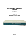
1
High performance access device
“qBRIDGE”
User’s Manual
qBRIDGE-101
Ethernet to E1 Converter/Bridge
Moscow 2007
2
qBRIDGE-101. Ethernet to E1 converter/Bridge.
User’s manual v.6
Contents
Revision history .......................................................................................................................................................... 3
1. Introduction............................................................................................................................................................. 4
1.1. Purpose and area of application ......................................................................................................................... 4
1.2. Advantages....................................................................................................................................................... 5
1.3. Features ............................................................................................................................................................ 5
1.4. Connectors, LED indicators and DIP-switches................................................................................................... 6
1.5. Application information .................................................................................................................................... 7
2. Device Configuration............................................................................................................................................... 7
2.1. Powerup ........................................................................................................................................................... 7
2.2. LAN: Frame buffer configuration (SW1.4 – SW1.3).......................................................................................... 9
2.3. LAN: Filtering mode (SW1.2)........................................................................................................................... 9
2.4. LAN: IEEE 802.3x flow control (SW1.1).......................................................................................................... 9
2.5. WAN (E1): Mode selection (SW2.8)................................................................................................................. 9
2.6. WAN (E1): Time slots selection (SW2.7 – SW5.1).......................................................................................... 10
2.7. WAN (E1): Receive equalizer gain limit (SW6.8)............................................................................................ 10
2.8. WAN (E1): CAS signaling (SW6.7)................................................................................................................ 10
2.9. WAN (E1): CRC4 multiframe (SW6.6)........................................................................................................... 10
2.10. WAN (E1): Transmit clock source selection (SW6.5) .................................................................................... 11
2.11. WAN (E1): Automatic remote alarm indication (SW6.4 - SW6.3).................................................................. 11
2.12. WAN (E1): Idle code (SW6.2) ...................................................................................................................... 11
2.13. WAN (E1): Remote loopback (SW6.1).......................................................................................................... 11
Appendix A. Connector pin-outs................................................................................................................................ 12
Appendix B. Ordering information ............................................................................................................................ 12
Appendix C. Checking in the box .............................................................................................................................. 12
Attention
When you receive devices you need to check your box and make sure that all items are inside (see
Appendix B). Especially check the presence of all required cables and certificate of guarantee. The
absence of certificate of guarantee with mark of distributor is a reason for refusal in after-sales service
and technical support from NSGate LTD.
© NSGate LTD 2007
NSGate
qBRIDGE-101. Ethernet to E1 converter/Bridge.
User’s manual v.6
Revision history
•
•
•
10.05.2006 First release of this document
12.10.2006 Paragraph 2.3 and ordering information have been reviewed
03.03.2007 Ordering information has been reviewed
NSGate
3
4
qBRIDGE-101. Ethernet to E1 converter/Bridge.
User’s manual v.6
1. Introduction
1.1. Purpose and area of application
qBRIDGE – is a series of low cost and high performance access devices (modems/ converters) functioning
in “Bridge connection” mode. They are meant for connecting together distant segments of Ethernet
10/100Base-TX LANs using different technologies of data transmission over copper or fiber lines. qBRIDGE is
a high performance bridge that encapsulates Ethernet frames into HDLC frames and visa versa. Peak
performance is 90000 frames per second. Frame buffer capacity is 340 frames. It’s possible to use any
synchronous serial interface as a WAN port. WAN interface speed is up to 50 Mbps. User can choose WAN
interface type from a set of already available interfaces. There is a possibility of manufacturing devices with
WAN interface by customer request. The “Bridge connection” mode provides transport for any protocol
including TCP/IP, IPX and so on. qBRIDGE supports transparent transmission of “long” Ethernet frames with
VLAN tag.
All qBRIDGE modifications can be used for point to point connection of distant LAN segments. Moreover
it’s possible to use some modifications for point-multipoint connection for example to connect remote users to
ISP. qBRIDGE-105 [sdsl] can be used as a CPE for 8-port mini-DSLAM NSG-800/maxS-8. qBRIDGE-106
[g.shdsl] can be used as a CPE for 24-port Ethernet-based mini-DSLAM NSG-800/maxS-24.
qBRIDGE series include modifications listed below:
qBRIDGE-100 : Bridge with one port 10/100M Ethernet & one port G.703 (E1 Unframed)
qBRIDGE-101 : Bridge with one port 10/100M Ethernet & one port E1 (E1 Framed/ Unframed)
qBRIDGE-201 : Bridge with one port 10/100M Ethernet & two ports E1 (E1 Framed/ Unframed)
qBRIDGE-401 : Bridge with four ports 10/100M Ethernet & four ports E1 (E1 Framed)
qBRIDGE-102 : Bridge with one port 10/100M Ethernet & one port E2
qBRIDGE-103 : Bridge with one port 10/100M Ethernet & one port E3
qBRIDGE-105 : Bridge with one port 10/100M Ethernet & one port SDSL
qBRIDGE-106 : Bridge with one port 10/100M Ethernet & one port G.SHDSL
qBRIDGE-206 : Bridge with one port 10/100M Ethernet & one/two/four ports G.SHDSL.bis
qBRIDGE-101 is a high performance converter/bridge. It’s suitable for connecting distant LAN
segments using standard E1 lines (E1 Framed/Unframed). qBRIDGE-101 has Framed/Unframed 2.048 Mbps
G.703 interface with maximum rich 2 km over 24AWG cable. Furthermore it can be used on dedicated lines.
qBRIDGE-101 supports all functionality of qBRIDGE-100 with additional features: line speed selection from
64 to 2048 Kbps with 64 Kbps (one time-slot) step; automatic alarm generation; fractional E1 mode; remote
loopback. All configuration is done using DIP-Switches. No terminal emulation program is needed.
The product is available as a standalone unit in metal case or as a card for 19" rack 6U.
NSGate
qBRIDGE-101. Ethernet to E1 converter/Bridge.
User’s manual v.6
1.2. Advantages
•
•
•
•
•
Simple configuring using DIP-switches
Ethernet 10/100Base-TX with auto-negotiation & auto-MDIX
VLAN Support: VLAN tag pass-through
High performance: Filtering and Forwarding- 90,000 pct/s; Frame Buffer- 340 frames
Small-size metal case or card for 19" rack 6U form factor
1.3. Features
LAN
•
•
•
•
IEEE 802.3/802.3u; IEEE 802.3x flow control
Half / Full duplex: 10/100Mbps - Half Duplex / 20/200Mbps - Full duplex
Auto-negotiation 10/100 Mbps & Auto-MDIX
Connector: RJ-45
“Bridge connection” mode
•
•
•
•
•
IEEE 802.1D transparent learning bridge
256 MAC-address table
IEEE 802.1q VLAN pass-through
Filtering and Forwarding: 90,000 packets/sec; Delay: 1 frame
Frame Buffer size – 340 frames
WAN port: Е1 Framed/Unframed
•
•
•
•
•
•
•
•
•
•
•
ITU–T G.703
Line speed: 64÷2048 Kbps ± 0,005% with 64 Kbps step full duplex
Line coding: HDB3
Line: 120Ω two-pair twisted cable
Fractional E1 mode
Automatic alarm generation
Remote loopback
Jitter tolerance according to ITU–T G.823
Improved receiver sensitivity: -43 dB at 1024 KHz
Selectable G.703 transmit clock source: local oscillator or recovery from E1 line
Connector: RJ-45
Other features
•
•
•
•
•
•
LED indicators
Dimensions: 182×140×30 mm
Power: 36÷72V DC or external 100÷240V AC to 9V DC adapter
Power consumption: 2W
Temperature: 0 ÷ 45 ºC
Humidity: 0 ÷ 95% without condensation
NSGate
5
6
qBRIDGE-101. Ethernet to E1 converter/Bridge.
User’s manual v.6
1.4. Connectors, LED indicators and DIP-switches
LEDs: LED indicators show state of qBRIDGE.
LEDs description:
PWR:
LAN 100M:
LAN 10M:
WAN LOS:
WAN LOF:
WAN ALM:
WAN ERR:
WAN ACT:
Connectors:
DC-IN:
LAN:
WAN:
On when power is applied to the device
ON/Blinking when LAN port is in 100 Mbps mode
ON/Blinking when LAN port is in 10 Mbps mode
ON when the E1 line interface detects a loss of carrier
ON when the E1 synchronizer is searching for the frame FAS/NFAS (LOF, loss of frame)
and multiframe CAS MFAS (CAS LOMF, loss of CAS multiframe), CRC4 (CRC4 LOMF,
loss of CRC4 multiframe)
This LED is refreshed every second.
ON (green) when RAI (ITU-T O.162 2.1.4) received
ON (red) when AIS (ITU-T O.162 1.6.1.2) received
ON (yellow) in remote loopback mode
This LED is refreshed every second.
ON (green) when there was less than 1E-3 line coding violations
ON (red) when there was more than 1E-3 line coding violations
ON (yellow) in remote loopback mode
Blinking when receiving/transmitting data through WAN port
Device has LAN connector (RJ-45), WAN connector (RJ-45) and power connector on the
rear panel
9 V or 36÷72 V DC power supply (see ordering information)
Ethernet 10/100BaseT (RJ–45 connector)
E1 WAN port (RJ–45)
NSGate
qBRIDGE-101. Ethernet to E1 converter/Bridge.
User’s manual v.6
7
1.5. Application information
E1
E1
SDH/PDH
qB-101
qB-101
…
…
Ethernet
Ethernet
Application 1. Connection of remote LANs over E1 channel
2. Device Configuration
2.1. Powerup
1. Configure qBRIDGE according paragraphs 2.2 – 2.13 of this manual.
2. Connect LAN port of the device to HUB/Switch or to a PC using a Patch Cord. Device supports auto-MDIX
therefore Patch Cords cable may be any type (cross or straight).
3. Connect WAN port (connector with “WAN” mark) to E1 channel. Use a cable with RJ–45 connector.
4. Connect power adapter (DC 9 V) or 36 ÷ 72 DC power supply (see ordering information) to the connector
with “DC–IN” mark.
ATTENTION!
Do not use 36 ÷ 72 V DC power supply for qBRIDGE-101 device which is shipped with
external 100÷240V AC to 9V DC power adapter. It can cause permanent device damage.
ATTENTION!
Connect 36 ÷ 72 V DC power supply to the qBRIDGE-101-DC using special cable
shipped with the device. Connect terminal with red wire to positive pole and terminal
with black wire to negative pole. Wrong polarity can cause permanent device damage.
ATTENTION!
You must turn off the power of the device before making any DIP-switch configuration
changes. Turn the power on again when configuration is complete.
NSGate
8
qBRIDGE-101. Ethernet to E1 converter/Bridge.
User’s manual v.6
To access Dip-switches SW1- SW6 you need to remove the cover of the device’s case. For this purpose twist
two screws on the bottom of the case and remove cover. Figure below shows the disposition of DIP-switches on
the PCB inside the case.
NSGate
qBRIDGE-101. Ethernet to E1 converter/Bridge.
User’s manual v.6
9
2.2. LAN: Frame buffer configuration (SW1.4 – SW1.3)
qBRIDGE has internal RAM (Frame Buffer) to store Ethernet frames. The entire Frame Buffer capacity
is 340 frames. One part of the Frame Buffer is used to store frames passing from LAN to WAN port and the
second part is used to store frames passing from WAN to LAN port. To increase device performance user can
configure the way of dividing of the Frame Buffer. Use DIP-switches SW1.3-SW1.4 for this purpose.
SW1.3
on
on
off
off
SW1.4
on
off
on
off
LAN-to-WAN buffer capacity
308 packets
170 packets
32 packets
reserved
WAN-to-LAN buffer capacity
32 packets
170 packets
308 packets
reserved
2.3. LAN: Filtering mode (SW1.2)
qBRIDGE supports Real-time MAC-address filtering with 256 address table and Automatic address
learning and aging. If filtering is enabled, only broadcast, multicast and destined for remote LAN frames are
forwarded to WAN. The address table can store up to 256 MAC-addresses and is automatically updated. The
individual address will be aged and deleted from address table if frames with this address have not been
received within 5 minutes. User can enable or disable filtering using DIP-switch SW1.2.
SW1.2
on
off
Filtering
enabled (default value)
disabled
2.4. LAN: IEEE 802.3x flow control (SW1.1)
qBRIDGE provides IEEE 802.3x flow control for more effective packet forwarding. If the number of packets
buffered in memory exceeds the predefined value, qBRIDGE transmits the PAUSE frame to pause the data
flow. When qBRIDGE receives the PAUSE frame it pauses the transmission until the requested time is expired.
User can enable or disable flow control support using DIP-switch SW1.1.
SW1.1
on
off
Flow control
enabled
disabled (default value)
2.5. WAN (E1): Mode selection (SW2.8)
WAN interface of qBRIDGE-101 can work both in framed (E1) and unframed (E12) mode. The difference
between E1 and E12 stream is (according to G.703.6) that E12 stream transmits bit sequence at speed 2048
Kbit/s and have no structure while Е1 stream has frame structure that is described in ITU-T G.704 specification.
Mode selection of WAN interface is controlled by DIP-switch SW2.8.
SW2.8
on
off
WAN interface mode
framed
unframed
NSGate
10
qBRIDGE-101. Ethernet to E1 converter/Bridge.
User’s manual v.6
2.6. WAN (E1): Time slots selection (SW2.7 – SW5.1)
When WAN interface is in framed mode user can select time slots that are used for Ethernet frames
transmission. Time slot 0 is always used for FAS, NFAS, international bits, CRC4 reminder and so on. Each of
31 alternate timeslots has corresponding DIP-switch and can be used for transmission of Ethernet frames. Whet
DIP-switch is on corresponding timeslot is not used for Ethernet transmission. Whet DIP-switch is off
corresponding timeslot is used for Ethernet transmission. If WAN interface is in unframed mode (SW2.8 off)
the state of SW2.7 – SW5.1 is ignored and all 2048 Kbit/s bit stream is used for transmission of Ethernet
frames.
Dip-switch
SW2.7
SW2.6
SW2.5
SW2.4
SW2.3
SW2.2
SW2.1
SW3.8
SW3.7
SW3.6
SW3.5
SW3.4
SW3.3
SW3.2
SW3.1
SW4.8
Timeslot
1
2
3
4
5
6
7
8
9
10
11
12
13
14
15
16
Dip-switch
SW4.7
SW4.6
SW4.5
SW4.4
SW4.3
SW4.2
SW4.1
SW5.8
SW5.7
SW5.6
SW5.5
SW5.4
SW5.3
SW5.2
SW5.1
Timeslot
17
18
19
20
21
22
23
24
25
26
27
28
29
30
31
2.7. WAN (E1): Receive equalizer gain limit (SW6.8)
It’s possible to adjust WAN interface receive equalizer gain limit using DIP-switch SW6.8. WAN
interface receive equalizer gain can be -12 or -43dB. When receive equalizer gain limit is -43 dB the maximum
rich over 24 AWG cable is up to 2 km.
SW6.8
off
on
Receive equalizer gain limit
-12 dB
-43 dB(default value)
2.8. WAN (E1): CAS signaling (SW6.7)
To enable/disable CAS signaling use DIP-switch SW6.7. Timeslot 16 is used to transmit CAS signaling. So
when CAS signaling is enabled timeslot 16 can’t be used for Ethernet frames transmission.
SW6.7
on
off
CAS signaling
disabled (default value)
enabled
2.9. WAN (E1): CRC4 multiframe (SW6.6)
DIP-switch SW6.6 is used to control CRC4 multiframe.
SW6.6
on
off
CRC4 multiframe
disabled (default value)
enabled
NSGate
qBRIDGE-101. Ethernet to E1 converter/Bridge.
User’s manual v.6
11
2.10. WAN (E1): Transmit clock source selection (SW6.5)
qBRIDGE-101 supports two modes of operation. Mode 1: E1 transmit clock is driven by local oscillator.
Mode 2: E1 transmit clock is driven by recovered receive clock. User can select mode of operation using DIPswitch SW6.5. User should choose Mode 2 (default) when connecting qBRIDGE-101 to E1 channels. When
using two qBRIDGE-101 to communicate over media transparent in terms of synchronization or over dedicated
copper line one of them must be in Mode 1 and another – in Mode 2.
SW6.5
on
off
E1 Transmit clock mode
Mode 1 (internal): E1 Transmit clock is driven by local oscillator
Mode 2 (recovered): E1 transmit clock is driven by recovered receive clock
2.11. WAN (E1): Automatic remote alarm indication (SW6.4 - SW6.3)
Use DIP-switches SW6.4 - SW6.3 to control remote alarm indication.
SW6.4
on
off
on
off
SW6.3
on
on
off
off
Remote alarm indication
disabled (default value)
transmit RAI
transmit AIS
transmit AIS
2.12. WAN (E1): Idle code (SW6.2)
Use DIP-switches SW6.2 to select idle code that is inserted to timeslots that are not used for Ethernet
transmission.
SW6.2
on
off
Idle code
0x55
0x7E
2.13. WAN (E1): Remote loopback (SW6.1)
Use DIP-switches SW6.1 to enable or disable remote loopback functionality. When remote loopback is
enabled all data received from E1 interface is looped back into the line. This feature is used for testing and
troubleshooting and isn’t enabled normally. LED indicators WAN ALM and WAN ERR are ON (yellow) in
remote loopback mode.
SW6.1
on
off
Remote loopback
disabled (default value)
enabled
WAN E1
NSGate
12
qBRIDGE-101. Ethernet to E1 converter/Bridge.
User’s manual v.6
Appendix A. Connector pin-outs
QBRIDGE-101. WAN (RJ-45)
Pin
1,2
4,5
3,6
Name
XMT (tip, ring)
RCV (tip, ring)
Chassis
Description
Transmit Data - out
Receive Data - in
Appendix B. Ordering information
P/N: 36BEU101 (qBRIDGE-101)
P/N: 36BED101 (qBRIDGE-101-DC)
P/N: 36BER101 (qBRIDGE-101-R)
100÷240V AC to 9V DC adapter
DC power supply 36÷72 V
Card for 19" rack 6U
Appendix C. Checking in the box
P/N: 36BEU101 (qBRIDGE-101)
P/N: 36BED101 (qBRIDGE-101-DC)
P/N: 36BER101 (qBRIDGE-101-R)
Power adapter (100÷240V AC to 9V DC)
Cable for DC 36 ÷ 72 power supply connection
Certificate of guarantee
User’s manual
Patch Cord cable “Straight RJ-45” or “Crossover RJ-45”
NSGate
1 (according to the order)
1 (according to the order)
1 (according to the order)
1 (with qBRIDGE-101 only)
1 (with qBRIDGE-101-DC only)
1
1 for two devices
1