1
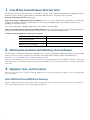
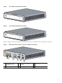
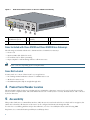
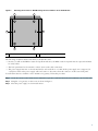
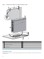
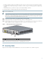
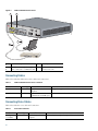
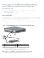
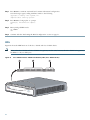
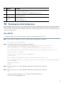
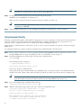
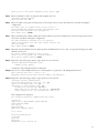
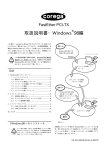
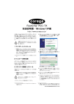
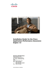
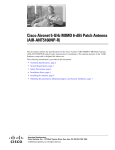
QUICK START GUIDE
Cisco VG202 and Cisco VG204 Voice Gateways
INCLUDING LICENSE AND WARRANTY
1
Cisco 90-Day Limited Hardware Warranty Terms
2
Obtaining Documentation and Submitting a Service Request
3
Equipment, Tools, and Accessories
4
Product Serial Number Location
5
Accessibility
6
Safety Information
7
Installing the Chassis
8
Connecting Cables
9
Powering On the Cisco VG202 and Cisco VG204 Voice Gateways
10 Performing the Initial Configuration
11 Verifying and Saving Your Configuration
12 Obtaining Documentation, Obtaining Support, and Security Guidelines
1 Cisco 90-Day Limited Hardware Warranty Terms
The following are special terms applicable to your hardware warranty. Your formal Warranty Statement, including the warranty
applicable to Cisco software, appears in the Cisco Information Booklet that accompanies your Cisco product.
Duration of Hardware Warranty: Ninety Days
Replacement, Repair or Refund Procedure for Hardware: Cisco or its service center will use commercially reasonable efforts
to ship a replacement part within ten (10) working days after receipt of the RMA request. Actual delivery times may vary
depending on Customer location.
Cisco reserves the right to refund the purchase price as its exclusive warranty remedy.
To Receive a Return Materials Authorization (RMA) Number: Please contact the party from whom you purchased the product.
If you purchased the product directly from Cisco, contact your Cisco Sales and Service Representative.
Complete the information below, and keep it for reference:
Product purchased from
Their telephone number
Product model and serial number
Maintenance contract number
2 Obtaining Documentation and Submitting a Service Request
For information on obtaining documentation, submitting a service request, and gathering additional information, see the monthly
What’s New in Cisco Product Documentation, which also lists all new and revised Cisco technical documentation, at:
http://www.cisco.com/en/US/docs/general/whatsnew/whatsnew.html
Subscribe to the What’s New in Cisco Product Documentation as a Really Simple Syndication (RSS) feed and set content to be
delivered directly to your desktop using a reader application. The RSS feeds are a free service and Cisco currently supports RSS
version 2.0.
3 Equipment, Tools, and Accessories
This section describes your voice gateway and the equipment, tools, and accessories that accompany or are not included with
the voice gateway.
Cisco VG202 and Cisco VG204 Voice Gateways
Figure 1 and Figure 2 show the front panels of the Cisco VG202 and Cisco VG204 Voice Gateways. The Cisco VG202 and
Cisco VG204 chassis include console, auxiliary, FXS, and FE ports.
2
Figure 1
Cisco VG202 Voice Gateway Front Panel
OK
0/0
FXS
0/1
FE
231877
0/0
0/1
VG202
Figure 2
Cisco VG204 Voice Gateway Front Panel
OK
0/0
0/1
FXS
0/2
0/3
FE
231875
0/0
0/1
VG204
Figure 3 and Figure 4 show the back panels and features of the Cisco VG202 and Cisco VG204 Voice Gateways.
Figure 3
FastEther
Back Panel Feature Locations on the Cisco VG202 Voice Gateway
net
VG202
CONSOLE
0/0
AUX
0/1
1
231880
FXS
0/1
2
0/0
12V DC
3
4
SA
5
6
1
Fast Ethernet port 1
Fast Ethernet port 0
2
Serial port—console or
auxiliary
3
FXS ports
4
Power connector
5
Chassis ground connection
6
Kensington security slot
3
Figure 4
Back Panel Feature Locations on the Cisco VG204 Voice Gateway
FastEther
VG204
net
CONSOLE
0/1
0/0
AUX
0/3
1
231940
FXS
0/2
0/1
0/0
12V DC
2
3
4
SA
5
6
1
Fast Ethernet port 1
Fast Ethernet port 0
2
Serial port—console or
auxiliary
3
FXS ports
4
Power connector
5
Chassis ground connection
6
Kensington security slot
Items Included with Cisco VG202 and Cisco VG204 Voice Gateways
The following are included with the Cisco VG202 and Cisco VG204 Voice Gateways:
• Power cord
• RJ-45-to-DB9 cable (labeled Console)
• Four rubber feet for desktop mounting
• Paper template for wall mounting with two wall-mount screws
Note
Power cords vary, depending upon local requirements.
Items Not Included
You may need one or more of these items for your application:
• PC running terminal emulation software for administrative access
• Modem for remote access
• Fast Ethernet RJ-45-to-RJ-45 straight-through cable
4 Product Serial Number Location
The serial number labels for the Cisco VG202 and Cisco VG204 Voice Gateways (routers) are located on the bottom of the
chassis, near the compliance label. The serial number label is 0.25 x 1 inch (0.635 x 2.54 cm). It has the letters “SN:” followed
by eleven characters.
5 Accessibility
This product family uses a command-line interface (CLI). Because it is text based and relies on a keyboard for navigation, the
CLI is 508 conformant. All functions of the router can be configured and monitored through the CLI.
To view Cisco accessibility guidelines and product adherence, see Cisco Accessibility Products at the following URL:
http://www.cisco.com/web/about/responsibility/accessibility/products
4
6 Safety Information
The following warnings apply to the Cisco VG202 and Cisco VG204 routers and should be read before installing this product.
Warning
IMPORTANT SAFETY INSTRUCTIONS
This warning symbol means danger. You are in a situation that could cause bodily injury. Before you work on any
equipment, be aware of the hazards involved with electrical circuitry and be familiar with standard practices for
preventing accidents. Use the statement number provided at the end of each warning to locate its translation in
the translated safety warnings that accompanied this device. Statement 1071
SAVE THESE INSTRUCTIONS
Warning
Do not work on the system, or connect or disconnect cables during periods of lightning activity. Statement 1001
Warning
Read the installation instructions before connecting the system to the power source. Statement 1004
Warning
This product relies on the building’s installation for short-circuit (overcurrent) protection. Ensure that the
protective device is rated not greater than:
120 VAC, 15A (240 VAC, 10A international) Statement 1005
Warning
This unit is intended for installation in restricted access areas. A restricted access area can be accessed only
through the use of a special tool, lock and key, or other means of security. Statement 1017
Warning
Only trained and qualified personnel should be allowed to install or replace this equipment. Statement 1030
Warning
This equipment must be installed and maintained by service personnel as defined by AS/NZS 3260. Incorrectly
connecting this equipment to a general-purpose outlet could be hazardous. The telecommunications lines must be
disconnected 1) before unplugging the main power connector or 2) while the housing is open, or both. Statement
1043
Warning
To avoid electric shock, do not connect safety extra-low voltage (SELV) circuits to telephone-network voltage
(TNV) circuits. LAN ports contain SELV circuits, and WAN ports contain TNV circuits. Some LAN and WAN ports
both use RJ-45 connectors. Use caution when connecting cables. Statement 1021
Warning
Hazardous network voltages are present in WAN ports regardless of whether power to the unit is OFF or ON. To
avoid electric shock, use caution when working near WAN ports. When detaching cables, detach the end away
from the unit first. Statement 1026
Warning
Do not use this product near water; for example, near a bath tub, wash bowl, kitchen sink or laundry tub, in a wet
basement, or near a swimming pool. Statement 1035
5
Warning
Never install telephone jacks in wet locations unless the jack is specifically designed for wet locations. Statement
1036
Warning
Never touch uninsulated telephone wires or terminals unless the telephone line has been disconnected at the
network interface. Statement 1037
Warning
Avoid using a telephone (other than a cordless type) during an electrical storm. There may be a remote risk of
electric shock from lightning. Statement 1038
Warning
To report a gas leak, do not use a telephone in the vicinity of the leak. Statement 1039
Warning
This equipment has been designed for connection to TN and IT power systems. Statement 1007
Warning
Before performing any of the following procedures, ensure that power is removed from the DC circuit. Statement
1003
Warning
This equipment needs to be grounded. Use a green and yellow 12 to 14 AWG ground wire to connect the host to
earth ground during normal use. Statement 242
Warning
The importance of proper grounding cannot be overemphasized. It will minimize the potential for damage to your
system and maximize safety at the system site. We recommend you consult a licensed electrician or your local
electric utility company if you have any questions. Statement 269
Warning
A ground wire must always be a single piece of wire. Never splice two wires together for a ground. Corrosion and
weathering can lead to a poor connection at the splice, making the ground ineffective and dangerous. Statement
270
Warning
To prevent accidental discharge in the event of a power line cross, route on-premise wiring away from power
cables and off-premise wiring, or use a grounded shield to separate the on-premise wiring from the power cables
and off-premise wiring. A power line cross is an event, such as a lightning strike, that causes a power surge.
Off-premise wiring is designed to withstand power line crosses. On-premise wiring is protected from power line
crosses by a device that provides overcurrent and overvoltage protection. Nevertheless, if the on-premise wiring
is in close proximity to, or not shielded from, the off-premise wiring or power cables during a lightning strike or
power surge, the on-premise wiring can carry a dangerous discharge to the attached interface, equipment, and
nearby personnel. Statement 338
Warning
There is the danger of explosion if the battery is replaced incorrectly. Replace the battery only with the same or
equivalent type recommended by the manufacturer. Dispose of used batteries according to the manufacturer’s
instructions. Statement 1015
6
Warning
Take care when connecting units to the supply circuit so that wiring is not overloaded. Statement 1018
Warning
For connections outside the building where the equipment is installed, the following ports must be connected
through an approved network termination unit with integral circuit protection.
FXS/T3/E3 Statement 1044
Warning
This equipment contains a ring signal generator (ringer), which is a source of hazardous voltage. Do not touch the
RJ-11 (phone) port wires (conductors), the conductors of a cable connected to the RJ-11 port, or the associated
circuit-board when the ringer is active. The ringer is activated by an incoming call. Statement 1042
Warning
This unit is intended to be mounted on a wall. Please read the wall mounting instructions carefully before
beginning installation. Failure to use the correct hardware or to follow the correct procedures could result in a
hazardous situation to people and damage to the system. Statement 248
Warning
To prevent bodily injury when mounting or servicing this unit in a rack, you must take special precautions to ensure
that the system remains stable. The following guidelines are provided to ensure your safety:
This unit should be mounted at the bottom of the rack if it is the only unit in the rack.
When mounting this unit in a partially filled rack, load the rack from the bottom to the top with the heaviest component at the
bottom of the rack.
If the rack is provided with stabilizing devices, install the stabilizers before mounting or servicing the unit in the rack.
Statement 1006
Warning
This equipment must be grounded. Never defeat the ground conductor or operate the equipment in the absence of
a suitably installed ground conductor. Contact the appropriate electrical inspection authority or an electrician if
you are uncertain that suitable grounding is available. Statement 1024
Warning
Use copper conductors only. Statement 1025
Warning
Ultimate disposal of this product should be handled according to all national laws and regulations. Statement 1040
Warning
Before opening the unit, disconnect the telephone-network cables to avoid contact with telephone-network
voltages. Statement 1041
Warning
No user-serviceable parts inside. Do not open. Statement 1073
Warning
Installation of the equipment must comply with local and national electrical codes. Statement 1074
7
7 Installing the Chassis
This section provides the procedures for installing and grounding the router chassis.
Chassis Installation Options
You can set the chassis on a desktop or mount it on a wall.
Tip
Before proceeding, consider the location of the equipment with respect to a good ground. See the “Grounding the
Chassis” section on page 10.
See the following instructions:
• Setting the Chassis on a Desktop, page 8
• Wall-Mounting the Chassis, page 8
• Grounding the Chassis, page 10
Caution
Use only the mounting hardware supplied with this product.
Setting the Chassis on a Desktop
You can place Cisco VG202 and Cisco VG204 routers on a desktop or shelf.
Caution
Do not place anything on top of the router that weighs more than 5 pounds (2.25 kg), and do not stack routers on
a desktop. Excessive distributed weight of more than 5 pounds or pound point load of 5 pounds on top could
damage the chassis.
After you install the router, you must connect the chassis to a reliable earth ground. For the chassis ground connection
procedures, see the “Grounding the Chassis” section on page 10.
Wall-Mounting the Chassis
You can mount the router on a wall or other vertical surface by using the molded mounting brackets on the bottom of the router
and two number-six, 3/4-inch (M3.5 x 20 mm) screws. You must provide the screws. Figure 5 shows the mounting-screw slots
on the router.
Caution
8
If you are mounting the router on drywall, use two hollow-wall anchors (1/8 inch with 5/16-inch drill bit, or M3
with 8-mm drill bit) to secure the screws. If the screws are not properly anchored, the strain of the network cable
connections could pull the router from the wall.
Figure 5
Mounting-Screw Slots for Wall-Mounting the Cisco VG202 or Cisco VG204 Router
1
1
2
231984
2
1
1
Rubber feet
1
2
Mounting-screw slots
The following conditions must be met when you mount the router:
• Because you will use the LEDs as status and problem indicators, the LEDs on the front panel must face upward and must
be easily visible.
• The back panel must face downward to reduce strain on the cable connections.
• The power supply must rest on a horizontal surface such as the floor or a table. If the power supply is not supported, it
could place strain on the power supply cable and cause it to disconnect from the connector on the router back panel.
To wall-mount the Cisco VG202 or Cisco VG204 voice gateway, follow this procedure:
Step 1
Secure two screws 5 7/16 inches (13.81 centimeters) apart into a wall and 1/8 inch (0.32 centimeter) out from the wall.
Step 2
Hang the voice gateway on the screws as shown in Figure 6.
Step 3
Place the power supply on a horizontal surface.
9
Figure 6
Mounting the Cisco VG202 or Cisco VG204 Voice Gateway on a Wall
2
1
3
7
4
6
231985
5
1
Two number-six, 3/4-in. screws
2
Distance between the two screws (5 7/16 in. [13.81 cm])
3
Cisco VG202 or Cisco VG204 voice gateway
4
Mounting-screw slots
5
Maximum distance between the voice gateway and the
power supply (6 ft [1.8 m])
6
Horizontal surface on which to set the power supply
7
Distance between the screw and the wall
(1/8 in. [0.32 cm])
Grounding the Chassis
You must connect the chassis to a reliable earth ground; the ground wire must be installed in accordance with local electrical
safety standards.
10
• For NEC-compliant grounding, use size AWG 14 (2 mm2) or larger wire and an appropriate user-supplied ring terminal.
• For EN/IEC 60950-compliant grounding, use size AWG 18 (1 mm2) or larger wire and an appropriate user-supplied ring
terminal.
• To ground the chassis, you will need a crimp tool and a number 2 Phillips screwdriver.
To connect the chassis to a reliable earth ground, perform the following steps:
Step 1
Locate a suitable ground.
Tip
Using a multimeter, measure the resistance between various possible ground locations, such as between the ground of
a junction box (outlet) and the ground of a power tap, between the ground of a junction box and a metal water pipe,
between the voice gateway chassis and the ground of a power tap, or between the chassis and the ground of a junction
box. A good ground connection should read between 0.0 and 0.5 ohm.
Step 2
Strip one end of the ground wire to the length required for the ring terminal.
Step 3
Crimp the ground wire to the ring terminal, using a crimp tool of the appropriate size.
Step 4
Attach the ring terminal to the chassis as shown in Figure 7. For a ring terminal, use one of the screws provided. Use a
number 2 Phillips screwdriver, and tighten the screws to a torque of 8 to 10 in-lb (0.9 to 1.1 N-m).
Figure 7
Chassis Ground Connection Using Ring Terminal
FastEther
net
VG204
CONSOLE
FXS
0/0
AUX
0/3
0/2
0/1
232069
0/1
0/0
12V DC
SA
1
1
Ring terminal attachment
Step 5
Connect the other end of the ground wire to a grounding point at your site.
8 Connecting Cables
Figure 8 shows the cabling for LAN and administrative access for the Cisco VG202 or Cisco VG204 voice gateway.
11
Figure 8
LAN and Administrative Access
2
1
FastEtherne
VG204
t
CONSOLE
FXS
0/0
AUX
0/3
0/2
0/1
272225
0/1
0/0
12V DC
SA
4
3
1
Fast Ethernet port
3
Fast Ethernet straight-through
cable connected to an Ethernet hub 4
2
Console port
RJ-45-to-DB9 console cable
connected to a PC
Connecting Cables
Table 1 describes the LAN and console cables and connections.
Table 1
LAN and Administrative Access Selection
Port or Connection
Color or Type Connected To
Cable
Fast Ethernet
Yellow
Fast Ethernet switch or
telephone
Straight-through Fast Ethernet cable (not included)
Console
Light blue
PC or ASCII terminal
RJ-45-to-DB9 console cable (included)
communication (COM) port
Connecting Voice Cables
Table 2 describes the voice cable and connection.
Table 2
Voice Cable Selection
Port/Interface
Color or Type
Connected To
Cable
Analog
voice/FXS
RJ-11
Distribution panel or
telephone
RJ-11-to-RJ-11 straight-through cable (not included)
12
9 Powering On the Cisco VG202 and Cisco VG204 Voice Gateways
This section provides the procedure for powering on your Cisco VG202 or Cisco VG204 voice gateway.
Checklist for Power-On
You are ready to power on the Cisco VG202 or Cisco VG204 voice gateway if it meets these requirements:
• The chassis is securely mounted.
• The power and interface cables are connected.
Power-On Procedure
Perform this procedure to power on your Cisco VG202 or Cisco VG204 voice gateway and to verify that the voice gateway
completes its initialization and self-test. Upon completion of these processes, the voice gateway is ready for you to configure.
To power on the Cisco VG202 or Cisco VG204 voice gateway, follow this procedure:
Plug the Cisco VG202 or Cisco VG204 voice gateway DC cable as shown in Figure 9. Then plug the AC plug into a
wall outlet.
Step 1
The green OK LED should light.
Figure 9
Connecting the External Power Supply to the Cisco VG202 and Cisco VG204 Voice Gateway
VG204
FastEtherne
t
CONSOLE
FXS
0/0
AUX
0/3
0/2
0/1
272269
0/1
0/0
12V DC
SA
1
2
4
3
1
DC plug
2
Power cord
3
Power adapter
4
AC plug
The following message appears at the end of the bootup messages:
--- System Configuration Dialog --Would you like to enter the initial configuration dialog? [yes/no]:
Step 2
Enter no to proceed with manual configuration using the command-line interface (CLI):
Would you like to enter the initial configuration dialog? [yes/no]: no
Would you like to terminate autoinstall? [yes]
13
Press Return to terminate autoinstall and continue with manual configuration.
Step 3
Several messages appear, ending with lines similar to the following:
Copyright (c) 2008 by cisco Systems, Inc.
Compiled <date> <time> by <person>
Press Return to bring up the VG> prompt:
Step 4
flashfs[4]: Initialization complete.
VG>
Enter privileged EXEC mode:
Step 5
VG> enable
VG#
Continue with the “Performing the Initial Configuration” section on page 15.
Step 6
LEDs
Figure 10 shows the LED functions of the Cisco VG202 and Cisco VG204 chassis.
LEDs on the Cisco VG202 and Cisco VG204 voice gateways are the same; however, the Cisco VG202 voice gateway
has LEDs for only two FXS ports.
Note
Figure 10
Cisco VG202 and Cisco VG204 Voice Gateway LEDs (Cisco VG204 Shown)
3
2
1
OK
0/0
0/1
FXS
0/2
0/3
0/0
FE
0/1
OK
0/0
0/1
FXS
0/2
0/0
FE
0/1
VG204
14
272226
0/3
No. LED/Color
Description
1
PWR OK—green
Off—no power
Steady on—normal operation
Slow blink—bootup phase or in ROMMON monitor mode
2
FXS ports 0
Off—On hook
through 3—green Steady On—Off hook
3
FE ports 0 to
1—green
Off—No link
Steady on—link
Blinking—TXD/RXD data
10 Performing the Initial Configuration
This section shows how to prepare the Cisco VG202 or Cisco VG204 voice gateway to perform basic communication functions.
You may initially configure your voice gateway by using the Cisco IOS command-line interface (CLI) or by using the setup
command facility. To create the initial configuration, the setup command facility prompts you for basic information about your
voice gateway and network.
Cisco IOS CLI
To configure the initial voice gateway settings by using the Cisco IOS CLI, follow these steps:
Step 1
Set up a console connection to your voice gateway. The following message is displayed:
...
voice gateway con0 is now available
Step 2
Press Return or Enter. The following message is displayed:
Cisco Configuration Professional Express (Cisco CP Express) is installed on this device.
This feature requires the one-time use of the username "cisco"
with the password "cisco." The default username and password have a privilege level of 15.
Please change these publicly known initial credentials using Cisco CP Express or the Cisco IOS CLI.
Here are the Cisco IOS commands.
username <myuser>
no username cisco
privilege 15 secret 0 <mypassword>
Replace <myuser> and <mypassword> with the username and password you want to use.
For more information about Cisco CP Express, please follow the instructions in the QUICK START GUIDE for
your voice gateway...
...
User Access Verification
Username:
Step 3
Enter the username cisco, and press Return or Enter. The following prompt is displayed:
Password:
Step 4
Enter the password cisco, and press Return or Enter. The following prompt is displayed:
VG#
A message is displayed that directs you to change the username and password.
You are now in privileged EXEC mode.
15
Note
Step 5
You must change the username and password before you log off the voice gateway. You cannot use the
username cisco or password cisco after you log off from this session.
To change the username and password, enter the following at the prompt:
username username privilege 15 secret 0 password
Where username and password are the username and password that you wish to use.
Note
Step 6
Use the copy running-config startup-config command at the privileged EXEC mode prompt (VG#) to save the
configuration to NVRAM.
Verify the initial configuration. See the “Verifying and Saving Your Configuration” section on page 18.
Setup Command Facility
The setup command facility guides you through the configuration process by prompting you for the specific information that is
needed to configure your system. Use the setup command facility to configure a hostname for the voice gateway, to set
passwords, and to configure an interface for communication with the management network.
To use the setup command facility, you will need to set up a console connection with the voice gateway and enter privileged
EXEC mode.
To configure the initial voice gateway settings by using the setup command facility, follow these steps:
Step 1
Step 2
Set up a console connection to your voice gateway and enter privileged EXEC mode. For instructions on how to enter
privileged EXEC mode see Step 1 through Step 4 in the “Cisco IOS CLI” section on page 15.
In privileged EXEC mode, at the prompt, enter the setup command facility.
yourname# setup
The following message is displayed:
--- System Configuration Dialog --Continue with configuration dialog? [yes/no]:
You are now in setup command facility.
The prompts in the setup command facility vary, depending on the voice gateway model, on the installed interface
modules, and on the software image. The following steps and the user entries (in bold) are shown as examples only.
Note
Step 3
If you make a mistake while using the setup command facility, you can exit and run the setup command facility
again. Press Ctrl-C, and enter the setup command at the privileged EXEC mode prompt (VG#).
To proceed using the setup command facility, enter yes:
Continue with configuration dialog? [yes/no]: yes
Step 4
When the following messages appear, enter yes to enter basic management setup:
At any point you may enter a question mark '?' for help.
Use ctrl-c to abort configuration dialog at any prompt.
Default settings are in square brackets '[]'.
Basic management setup configures only enough connectivity
for management of the system, extended setup will ask you
to configure each interface on the system
16
Would you like to enter basic management setup? [yes/no]: yes
Step 5
Enter a hostname for the voice gateway (this example uses VG):
Configuring global parameters:
Enter host name [VG]: VG
Step 6
Enter an enable secret password. This password is encrypted (more secure) and cannot be seen when viewing the
configuration.
The enable secret is a password used to protect access to
privileged EXEC and configuration modes. This password, after
entered, becomes encrypted in the configuration.
Enter enable secret: xxxxxx
Step 7
Enter an enable password that is different from the enable secret password. This password is not encrypted (less secure)
and can be seen when viewing the configuration.
The enable password is used when you do not specify an
enable secret password, with some older software versions, and
some boot images.
Enter enable password: xxxxxx
Step 8
Enter the virtual terminal password, which prevents unauthenticated access to the voice gateway through ports other
than the console port:
The virtual terminal password is used to protect
access to the voice gateway over a network interface.
Enter virtual terminal password: xxxxxx
Step 9
Respond to the following prompts as appropriate for your network:
Configure SNMP Network Management? [yes]:
Community string [public]:
A summary of the available interfaces is displayed.
Step 10 Choose one of the available interfaces for connecting the voice gateway to the management network:
Enter interface name used to connect to the
management network from the above interface summary: fastethernet0/0
Step 11 Respond to the following prompts as appropriate for your network:
Configuring interface FastEthernet0/0:
Use the 100 Base-TX (RJ-45) connector? [yes]: yes
Operate in full-duplex mode? [no]: yes
Configure IP on this interface? [yes]: yes
IP address for this interface: 172.1.2.3
Subnet mask for this interface [255.255.0.0] : 255.255.0.0
Class B network is 172.1.0.0, 26 subnet bits; mask is /16
The configuration is displayed:
The following configuration command script was created:
hostname VG
enable secret 5 $1$D5P6$PYx41/lQIASK.HcSbfO5q1
enable password xxxxxx
line vty 0 4
password xxxxxx
snmp-server community public
!
no ip routing
!
interface FastEthernet0/0
no shutdown
speed 100
duplex auto
ip address 172.1.2.3 255.255.0.0
17
!
Step 12 Respond to the following prompts. Enter 2 to save the initial configuration.
[0] Go to the IOS command prompt without saving this config.
[1] Return if possible to the setup without saving this config.
[2] Save this configuration to nvram and exit.
Enter your selection [2]: 2
Building configuration...
Use the enabled mode 'configure' command to modify this configuration.
Press RETURN to get started! RETURN
The user prompt is displayed.
VG>
Step 13 Verify the initial configuration. See the “Verifying and Saving Your Configuration” section on page 18 for the verification
procedure.
After creating the initial configuration file, you can use the Cisco IOS CLI to perform further configuration.
11 Verifying and Saving Your Configuration
To verify the configuration and save it in NVRAM so that the configuration remains in effect if the voice gateway is restarted,
enter the following commands:
Command
Description
Step 1
VG# show running-config
Displays the current operating configuration, including any
changes you have made.
Step 2
VG# show startup-config
Displays the configuration currently stored in NVRAM.
Step 3
VG# show voice port summary
Displays the voice port parameter settings.
Step 4
VG# copy running-config startup-config
Writes the current running configuration to NVRAM, where it
overwrites the startup configuration and becomes the new startup
configuration.
Note
If you reboot the Cisco VG204 router or turn off the
power before you complete this step, you lose the
configuration.
12 Obtaining Documentation, Obtaining Support, and Security Guidelines
For information on obtaining documentation, obtaining support, providing documentation feedback, security guidelines,
and also recommended aliases and general Cisco documents, see the monthly What’s New in Cisco Product Documentation,
which also lists all new and revised Cisco technical documentation, at:
http://www.cisco.com/en/US/docs/general/whatsnew/whatsnew.html
18
19
Americas Headquarters
Cisco Systems, Inc.
170 West Tasman Drive
San Jose, CA 95134-1706
USA
www.cisco.com
Tel: 408 526-4000
800 553-NETS (6387)
Fax: 408 527-0883
Asia Pacific Headquarters
Cisco Systems, Inc.
168 Robinson Road
#28-01 Capital Tower
Singapore 068912
www.cisco.com
Tel: +65 6317 7777
Fax: +65 6317 7799
Europe Headquarters
Cisco Systems International BV
Haarlerbergpark
Haarlerbergweg 13-19
1101 CH Amsterdam
The Netherlands
www-europe.cisco.com
Tel: 31 0 800 020 0791
Fax: 31 0 20 357 1100
Cisco has more than 200 offices worldwide. Addresses, phone numbers, and fax numbers are listed on the
Cisco Website at www.cisco.com/go/offices.
CCDE, CCENT, Cisco Eos, Cisco Lumin, Cisco Nexus, Cisco StadiumVision, Cisco TelePresence, Cisco WebEx, the Cisco logo, DCE, and Welcome
to the Human Network are trademarks; Changing the Way We Work, Live, Play, and Learn and Cisco Store are service marks; and Access Registrar,
Aironet, AsyncOS, Bringing the Meeting To You, Catalyst, CCDA, CCDP, CCIE, CCIP, CCNA, CCNP, CCSP, CCVP, Cisco, the Cisco Certified
Internetwork Expert logo, Cisco IOS, Cisco Press, Cisco Systems, Cisco Systems Capital, the Cisco Systems logo, Cisco Unity, Collaboration
Without Limitation, EtherFast, EtherSwitch, Event Center, Fast Step, Follow Me Browsing, FormShare, GigaDrive, HomeLink, Internet Quotient,
IOS, iPhone, iQuick Study, IronPort, the IronPort logo, LightStream, Linksys, MediaTone, MeetingPlace, MeetingPlace Chime Sound, MGX,
Networkers, Networking Academy, Network Registrar, PCNow, PIX, PowerPanels, ProConnect, ScriptShare, SenderBase, SMARTnet, Spectrum
Expert, StackWise, The Fastest Way to Increase Your Internet Quotient, TransPath, WebEx, and the WebEx logo are registered trademarks of
Cisco Systems, Inc. and/or its affiliates in the United States and certain other countries.
All other trademarks mentioned in this document or website are the property of their respective owners. The use of the word partner does not imply
a partnership relationship between Cisco and any other company. (0809R)
© 2008 Cisco Systems, Inc. All rights reserved.
OL-16690-01