1
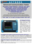
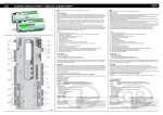
ACT6000
Advanced Communication Tester
SINE SIGNAL & NOISE GENERATOR - SELECTIVE LEVEL METER
CROSS TALK METER - SPECTRUM & NETWORK ANALYZER
LONGITUDINAL BALANCE & RETURN LOSS METER
MICROINTERRUPTION & IMPULSIVE NOISE METER
VOLTAGE - RESISTANCE - CAPACITANCE METER
TDR & RESISTANCE FAULT LOCATOR
POTS DEVICE SIMULATOR
ALL ON THE PALM OF YOUR HAND!
This new instrument combining various kinds of transmission, metallic and special tests,
may be considered up to today the most advanced Test Set for qualifying and maintenance
of advanced transmission systems and copper pairs used for various telecommunication services:
€POTS €ISDN €T1 €E1 €HDSL 1/2P €SHDSL €ADSL €ADSL2+ €VDSL2
ERGONOMIC CHARACTERISTICS
One of ACT6000 most interesting
features is the colour LCD high
resolution graphic display, a real
“window” on the most advanced
measurements’ world.
The alphanumeric keypad, as well
as the function-keys, grant to the
instrument a high operating level.
Moreover, don’t miss to notice that,
due to its accurate and intuitive
“Human Machine and Graphics User
Interface”, this instrument doesn’t
need the help of the user’s manual,
if not to arrange and carry out
unusual
measurements
and/or
settings.
DATA-COMMUNICATION CHANNELS & COPPER PAIRS QUALIFICATION / CERTIFICATION
One ACT6000 can perform easy and quick “Single-End Line Tests” or very accurate “End-to-End Line
Tests” if coupled with another ACT6000. The wide kind of measurements of the ACT6000 allows the
qualification and certification on various communication carriers and copper pairs used for digital streams
with a frequency occupancy up to 6 MHz (or 30 MHz optional); moreover, the instrument can automatically
extrapolate the ADSL and VDSL maximum expected data rate of the copper line under test.
COPPER PAIRS DIAGNOSTIC & FAULTS FINDING / LOCATION
ACT6000 can be configured for high troubleshooting mission, by special functions and internal optional
modules.
The complete adoption of these modules allows the simple and fast finding and localization of anomalies
and/or faults on the copper line and communication systems.
ACT6000 – TECHNICAL CHARACTERISTICS
General
Case ........................................... : ABS shielded for EMI / EMC compatibility.
Connections ............................... : € "RTX" connectors IN/OUT and •TX‚ OUT triple banana-jack;
€ polarized connector for external supply;
€ RJ-45/4 connector for headset;
€ USB & RS232 port for PC connector;
€ USB for Pen-drive connector.
Display........................................ : LCD color 320 x 240 pixel (1/4 VGA) back-lighted and reverse.
Power supply (internal)............... : € rechargeable battery pack (green) 2 x 4 NiMh 1.2 V / 2.7A, for
8 hours (mid.) of continue operation with battery state indication.
€ external: from 16,5 to 26,5 Vdc / max 2,5 Ah.
Dimensions and Weight.............. : 150 x 210 x 50 mm / 1,5 Kg. (batteries included).
Temperature range..................... : operative: 0 ƒ +45„ C. / stock -20 ƒ +70„ C.
Humidity range ........................... : 5 ƒ 90% no-condensing.
Overvoltage Protection ............... : In/Out connectors up to 150 Vdc / 140 Vpp.
Reference Frequency accuracy.. : …1 ppm within the operating temperature …2 ppm/year.
Reference Level accuracy††... : …0.025% within the operating temp. …0.025% / year.
CE mark - EMC †††††††: Directive 2004/108/CE, 89/336/EEC, Decree 2007/194
CISPR 11, ISO 14253 and CEI EN: 61326/A1/A2, 55011,
61000-4-2, 61000-4-3, 61000-4-4, 61000-4-6, 61000-4-11.
Special Features and Setup ....... : € Software update and Results Export using Pen Drive;
€ Results Storage on internal flash memory;
€ Remote control by USB port interface*.
Signal Generator
Sine output frequency range ...... : € base band: from 20 Hz to 20 kHz;
€ middle band: from 20 kHz to 6 MHz;
€ high band (optional): from 0.02 to 30 MHz.
Frequency Resolution................. : 1 Hz up to 9.999999 MHz; 10 Hz over 10.0 MHz.
Frequency setup mode†††... . : manual on single frequency and steps mode on
programmable band / steps.
Output level ................................ : -60 ƒ +20 dBm @ 150 ‡ / 0.1 dB steps.
Output level accuracy................. : …0.2 dB from 400 Hz to 20 kHz @ 600 ‡;
…0.2 dB up to 2 MHz, …0.3 dB up to 6 MHz; @ 100 ‡;
…0.5 dB up to 30 MHz @ 100 ‡.
Balanced output impedances ..... : € base band: 150, 200 and 600 ‡;
€ middle band: 100, 110, 120, 135, 150 and 1350 ‡;
€ high band 100 ‡.
Unbalanced output impedances . : 50 and 75 ‡ by Banana/BNC optional adapter.
White Noise Generator .............. : 1 kHz ƒ 6 MHz / -74 ƒ -144 dBm/Hz / 0.1 dB steps.
Signal & Level Meter
Frequency range ........................ : from 20 Hz to 6 MHz (two bands) base version;
up to a 30 MHz (with EBM 30 optional module).
Manual tuning / resolution††.. . : 1 Hz up to 9.999999 MHz; 10 Hz over 10.0 MHz.
Level measurements mode†† . : absolute (dBm or dBV or Volt) or relative (dBr).
Input range†††††††...†.. : -120 ƒ +12 dBm @ 100 ‡ / 0.1 dB Resolution.
Level meter accuracy†††.†. . : …0.2 dB from 400 Hz to 20 kHz @ 600 ‡;
…0.2 dB up to 2 MHz, …0.3 dB up to 6 MHz; @ 100 ‡;
…0.5 dB up to 30 MHz @ 100 ‡.
Noise floor (TX OFF)††††.... : ˆ-140 dBm/Hz
Frequency Meter sensitivity........ : ˆ-40 dBm on wide band or selective mode.
* by Advanced Software 2
Input impedances balanced........ : € base band: 150, 200, 600 and >10 k‡;
€ middle band: 100, 110, 120, 135, 150 ‡;
€ high band 100 ‡.
Input impedances unbalanced.... : 50 and 75 ‡ by Banana/BNC adapter.
Noise filters††††††..††. . : € base band: psophometric; C-Message; 0.3 ? 3.4
kHz, 0.02 ƒ 3.4 kHz, 0.3 ƒ 6.0 kHz, 0.02 ƒ 6.0 kHz,
0.3 ƒ 15.0 kHz, 0.02 ƒ 15.0 kHz, 0.3 ƒ 20.0 kHz,
20 ƒ 20.0 kHz, 20.0 kHz flat,
€ middle/high band: E, F, G and VDSL.2 -12 -17 and 30.
Selective filters / notch†††† . : € base band: (200 Hz ƒ 20 kHz) pass band and notch
for S/N+D (dB and %) test; 10 Hz @ fo <200 Hz;
5% fo @ >200Hz fo <4 kHz; 200 Hz @ fo >4 kHz.
selective for telegr.chann.: 120, 240, 360, 480 Hz.
€ high band (20 kHz ƒ 6 or 30 MHz) selective: 25,
100, 200, 400 Hz and 1.74, 3.1, 4.0, 8.0, 16.0 kHz.
Spectrum and Network Analyzer
Frequency range ........................ : € from 200 Hz to 6 MHz (two band) base version;
€ up to 30 MHz (by optional module EBM 30).
Input impedances balanced........ : € base band: 150, 200, 600 and >10 k‡ balance;
€ middle band: 100, 110, 120, 135, 150 ‡;
€ high band 100 ‡.
Input impedances unbalanced.... : 50 and 75 ‡ by Banana/BNC optional adapter.
- Base band ............................... : 200 ƒ 25000 Hz, by FFT analyzer (Kaiser window).
Span ......................................... : 6250, 12500 and 25000 Hz.
Resolution horizz. / vertical....... : - 250 pixel / 10 div. : 625, 1.250, 2.500 Hz / div.;
- 192 pixel / 8 div.: 1, 2, 3 ƒ 20 dB / div.
Resolution (BW) ....................... : 50, 100, 200 .. Hz (other resolutions are interpolated).
- Middle band ............................ : 1 kHz to 6 (30) MHz, by Digital SSB quad. conversion.
Span ......................................... : 30 ranges: from 10 to 8000 kHz, 10 per decade.
Resolution horizz. / vertical....... : - 250 pixel / 10 div: 1, 2, 4, 8, 16.. ƒ 800 kHz / div.
- 192 pixel / 8 div.: 1 ƒ 20 dB / div.
Resolution (BW) ....................... : 0.2, 0.5, 1, 2, 5, 8 kHz (other resolutions are Interpol.)
- High band measure method .... : Double conversion receiver by int. optional module.
Span ......................................... : 0 ƒ 12, 0 ƒ 18 and 0 ƒ 30 MHz.
Level reading mode .................... : absolute: dBm, dBm/Hz, dBV and dBr (relative).
Measurement mode†††......... : normal, peak (max, mean or min. value), 2 Wires +/(for Return-Loss measurement), 2 Wires +/+ (for
Longitudinal Balancement measurement) and 4 Wires.
Input range ................................. : ˆ -100 ƒ +12 dBm @ 100 ‡
Noise floor .................................. : ˆ -140 dBm/Hz @ 100 ‡ (high band) with 16 kHz filter.
Resolution marker (lev. / freq.) ... : 0.1 dB / as selected resolution (BW).
Network Analyzer ....................... : by tracking generator or single freq. in 2/4 wires mode.
Mix measurements Generator/Meter and Network Analyzer
€ Cross-Talk (4 Wires)
Test mode††††††.. ........ : Near-End (Single-End) and Far-End (End-to-End)
single frequency or scanner on limited band.
Frequency range ..................... : 200 Hz ƒ 6 MHz (up to 30 MHz - EBM 30 opt. module)
Measurement accuracy ........... : up to 2 MHz: …1 dB / between 0 ƒ -90 dB;
up to 6 MHz: …2 dB / between 0 ƒ -86 dB;
up to 30 MHz: …3 dB / between 0 ƒ -80 dB.
Intrinsic crosstalk†††††.. . : ˆ- 90 dB (with precise resistive load).
€ Return Loss ( 2 wires)
Test mode †††† ................ : single frequency or scanner on limited band.
Frequency range ..................... : 200 Hz ƒ 6 MHz (up to 30 MHz - EBM 30 opt. module)
Measurement accuracy ........... : up to 2 MHz: …1 dB / between 0 ƒ -50 dB;
up to 6 MHz: …2 dB / between 0 ƒ -46 dB;
up to 30 MHz: …3 dB / between 0 ƒ -40 dB.
€ Longitudinal Balance Loss ( 2 Wires + Gnd)
Test mode †††† ................ : single frequency or scanner on limited band.
Frequency range ..................... : 200 Hz ƒ 6 MHz.
Measurement accuracy ........... : up to 2 MHz: …1 dB / between 0 ƒ -60 dB;
up to 6 MHz: …2 dB / between 0 ƒ -56 dB;
€ Single-End Insertion Loss (included on the Single-End-Line-Testing) *
Measuring Mode / readout........ : by FDR technology on High-Band / Spectral readout.
Operating Band ........................ : direct: 100 kHz ƒ 1000 kHz
Graphic Extrapolation ............... : 20 kHz ƒ 6MHz and 30 MHz.
Operative Impedance ............... : 120 ‡ (default) balanced line.
Accuracy................................... : …1 dB up to 2.2 MHz; …2 dB up to 30 MHz.
Operative limits......................... : minimum line length: 100 meters;
maximum line length: 4 km (0.4 mm wire gauge).
Event Tests
€ Micro-Interruptions - O.62 (base band) and wide band
Threshold level ........................ : -3 ƒ -20 dB - 2 kHz Test Tone (default) or on
programmable frequency up to 6 MHz.
Monitoring time ........................ : 4 min. ƒ 24 ours.
Events indicators ..................... : 5 Counters (0.3ms ƒ >1min); Event/Time ; Secs. with Events.
Readout................................... : Tabular and Time Domain Histogram representation.
Measure facilities..................... : reference tone output from TX connector for loopback tests.
€ Impulsive Noise O.71 (base band) and wide band
- Threshold level......................... : 0 ƒ -60 dBm.
- Base band BW filters............. : 200 ƒ 12,000 Hz Flat, 600 ƒ 3,000 Hz, 300 ƒ 500 Hz.
- DSL bands / PB filters ........... : 20 kHz ƒ 6 / 30 MHz (some sectors of E,F,G and VDSL filter) **
- Monitoring time...................... : 4 min. ƒ 24 hours.
- Events indicators................... : 1 Event Counter; Event/Time Ratio; Secs with Events.
- Readout................................. : Tabular and Time Domain Histogram representation.
Special Measurements
€ Line Immunity by White Noise injection
- Output level range ................. : -70 ƒ -144 dBm/Hz @ Zref. 100‡ - 0.1 dB Resolution.
- Output impedance ................. : 100, 120, 135, 150 and 1350 ‡ (balanced).
- Bandwidth ............................. : 1 kHz ƒ 6 MHz.
€ TDR Fault locator
Distance ranges††††††... . : 90, 180, 450, 900, 1800, 3600, 7200 m. @ 0.600 PVF.
Zoom†††††††††††.. . : vertical: -8 ƒ +77 dB; horizontal : 1x, 2x, 4x.
Distance resolution (by marker).. : - minimum range: about 0.4 meters (or 1 feet);
- maximum range: about 40 meters (or 100 feet).
Operative mode††††††† . : single line (2 wires), Crosstalk (4 Wire), Differential by
relative comparison with other line; Monitoring to
events localization by Peak mode (Sample & Hold).
Pulse output level†††.††. ... : short and long: 2.2 Vpp; Boost: 5.5 Vpp.
Pulse length†††††††† ... : automatic on range selection, from 10 to 5000 ns.;
IN/OUT impedance†..††††. : 100, 110, 120, 135, 150 ‡ (balanced).
TGC (automatic gain control).. ... : 0 ƒ 6 dB/km.
Propagation velocity††††..... : PVF: 0.300 to 0.999 o PV (90 to 300 m/‰s).
€ Digital Multimeter DC / AC (by DMM optional module)
Measuring mode......................... : automatic between a-b; a-c (Gnd); b-c (Gnd) and reverse.
DC Voltage, Range / Accuracy... : 0 ƒ 140 Vdc / ˆ 2% of reading …1 digit.
AC Voltage, Range / Accuracy ... : 0 ƒ 100 Vrms / ˆ 2% of reading …1 digit (up to 1kHz).
Resistance / Insulation
- Test Voltage ............................. : ˆ 100 Vdc (with current limitation 1mA max).
- Range / Accuracy ..................... : 5 ‡ ƒ 1 G‡ /: ˆ 2% of reading … digit.
LINE LENGTH BY LOOP RESISTANCE
- Line length evaluation .............. : (as function of measured resistance)
- Line Gauges setting ...†††† : from 0.4 to 0.9 mm or from AWG 26 to AWG 19.
- Line Resistance correction
: from 1.01 to 1.60 x standard copper resistance.
- Line Temperature setting
: set from -20„ ? +60„ C.
- Range / Resolution................... : 0 to 99.999 kUnits (meters or feet) / 1 units.
DC CAPACITANCE (time of DC discharge method)
- Test Voltage ............................. : ˆ 100 Vdc
- Range / Accuracy .................... : > 10 nF ƒ 10 ‰F / ˆ5% of reading … 1 digit.
AC CAPACITANCE (by capacitive bridge)
Measuring mode......................... : by 1 kHz tone Š 1.1 Vpp between a-b wires.
Range / Resolution ..................... : 0.1 to 3000 nF / 0.1 nF.
Accuracy..................................... : … 1% of reading … 1 nF @ C <500 nF;
… 5% of reading … 1 digit @ C >500 nF and < 3000 nF.
LINE LENGTH BY CAPACITANCE
Line length estimation................. : (as function of measured capacitance):
Line Capacitance setup .............. : 10.0 to 300.0 pF / Length Unit.
Range / Resolution / Accuracy ... : 1 to 99999 Units (m. or ft.) / 1 units / as derived from
measured capacitance.
RFL (Resistance Fault Locator)
- Loop resistance ....................... : 4 k‡ maximum.
- Fault resistance ....................... : from 100 ‡ to 20 M‡ maximum.
- Accuracy of RTF @ 1 M? . ...... : … 0.1% of Loop resistance.
- Readout .................................. : graphic representation and action help.
RBAL (Resistance Balancement): starting from 5 ‡.
- Readout ................................... : graphic representation and action help.
MULTI GAUGES facilities **....... : to set 3 sectors of multi gauges lines to compute the line length or
fault localization by loop resistance / line insulation.
€ POTS Subscriber Simulator (by optional module installed on DMM module)
Dial Encoder............................... : - Pulse, programmable on duration/ratio (default 100 ms / 40/60%);
- DTMF std. tones, programmable on Level, Duration, Inter-tone.
Ring Detect. Range & Meas ....... : Level: 10 ƒ 90 Vrms; Frequency: 15 ƒ 70 Hz.
Ring Detector AC Load............... : R 7310 ‡ … 2% in series + 940nF …10% capacitor.
Ring current self limitation ......... : ˆ 15 mA peak ; safety fold-back limited.
On Hook / Break & Make specs.. : R = 120 ‡ …2% @ I = 100 mA; Voffset = 4 Vdc.
Single End Line Tests for line pre-qualification *
With single ACT6000 on open lines, 2 or [4] Wire mode:
One button test (automatic sequence):
Metallics: AC / DC Voltage, DC Insulation, AC / DC Capacitance, End-Of-Line (by TDR).
Transmissives (Wide band): Noise (local), Return-Loss, Longitudinal Balance-Loss, “FDR” Insertion-loss
& frequency response estimation, Far-end Noise (estimation), SNR prediction, ADSL - ADSL2+ and
VDSL 1 / 2 ***, Bit-Rate prediction, [NEXT].
Single transmissives tests (real time spectral readout): Noise, Return-Loss, Longitudinal Balance-Loss,
Next and PSD.
Automatic End-to-End Test for line qualification **
With two ACT6000 (Master/Slave configuration) for Double-End Tests, 2 or [4] Wire mode:
Only Transmissives (base and wide band): Noise (bilateral), Return-Loss (bilateral), Longitudinal
Balance-Loss (bilateral “LCTL”), Insertion-Loss, SNR (bilateral), ADSL - ADSL2+ and VDSL*** Bit-Rate
evaluation (Up & Down stream), [NEXT and FEXT].
Masks for pre-configured SELT or DELT line tests *
€ Wide band: ISDN, HDSL 1p, HDSL 2p, E1, T1, SHDSL, ADSL, ADSL2+ and VDSL2 -12, 17, 30.
Masks for pre-configured DELT telephone tests **
€ Base band: M1040, M1020, G.712E2, EURO16k, EURO32k, MIL16k, MIL32k
Notes:
* by Advanced Software 1
** by Advanced Software 2
*** by adoption of EBM 30 optional module
Supplied Accessories (base kit):
ACT6000 Base Instrument, included:
- Nylon Carrying Case with pocket for accessories;
- User Guide (English or Italian language, as requested);
- AC Power Supply and Battery Charger (Line Input: 100 - 220 Vac; Output: 20 Vdc; 1.4A);
- Banana-Banana + Crocodiles shielded cable (2.30m total length);
- Ground Cable unipolar Banana-Crocodile cable;
Extra cost Accessories and Optional Modules
- ASW1 - Advanced Software 1 (see the above description).
- ASW2 - Advanced Software 2 (to be develop), it will include the End-to-End (Master/Slave) line test,
PC utility programs to: SELT Remote Control, SW Update, Capture Screen, Export & Read Saved Tests,
Masks Editor etc..
- ACT-11 POTS Module (Subscriber Simulator Module for POTS for signalling tests) ;
- ACT-12 DMM Module (Digital Multimeter Module for metallic tests);
- ACT-13 EBM30 Module (Extension Band Module for 30 MHz operation);
- ACT-14 USB Pen-Drive 4 GB;
- ACT-15 Probes to perform Medium & High Band PSD measurement on lines fed;
- ALT-05 Headset with 2m cable and RJ-45/4 connector;
- ALT-09 Resistive Termination Set (100, 120, 135, 150 and 600 ? );
- ALT-16 Banana to BNC Adapter.
ATEN S.r.l. - Via dei Lavoratori, 180 - 04100 LATINA - ITALY
Tel.: +39 0773 240696 Fax: +39 0773 240676 - e-mail: [email protected] - Web: www.aten.it
Aten S.r.l. reserves the right to change this preliminary specifications without prior notice