1
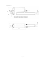
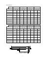
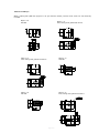
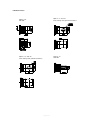
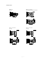
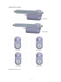
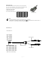
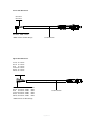
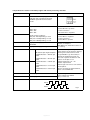
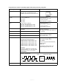
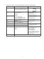
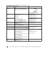
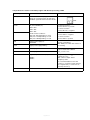
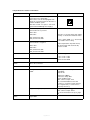
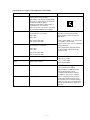
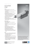
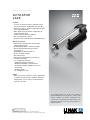
P R O D U C T D ATA S H E E T
ACTUATOR
LA36
Features:
• 12, 24 or 36 V DC Permanent magnetic motor (IC only 12/24 V DC, IECEx/ATEX only 24 V DC)
• Thrust from 500 N - 10,000 N depending on gear ratio and spindle pitch
• Max. speed up to 160 mm/sec. depending on load and spindle pitch
• Stroke length from 100 to 999 mm
• Non rotating piston rod eye
• Protection class: IP66 (dynamic) and IP69K (static)
Options in general:
• Mechanical overload protection through
integrated slip clutch
• Exchangeable cables in different lengths
• Special anodised housing for extreme environments
• IECEx/ATEX certified for Zone 21
• Built-in endstop switches
• Hall effect sensor
• Mechanical potentiometer (not with IC)
• IC options including:
- IC - Integrated Controller
- Integrated Parallel Controller
- Modbus and LINbus communication
- Analogue or digital feedback for precise positioning
- Endstop signals
- PC configuration tool
Usage:
• Duty cycle at max. load from 5 -20% depending on load and stroke length. Ambient operating temperature -30°C to +65°C, full performance
from +5°C to +40°C
The actuator LA36 is one of the most solid and
powerful LINAK actuators, designed to operate under
extreme conditions. The LA36 is a maintenance-free
product with a long lifetime and a high IP degree. This
high-quality actuator offers a very strong alternative to
hydraulic solutions.
This TECHLINE® actuator comes with IC - Integrated controller.
For more information on our IC options, please see: www.linak.com/techline
Page 1 of 32
Contents
Chapter 1
Specifications............................................................................................................................... 3
Technical specifications............................................................................................................... 4
LA36 Load versus Stroke Length................................................................................................. 5
Stroke and built-in tolerances..................................................................................................... 5
LA36 Dimensions......................................................................................................................... 6
Built-in dimensions....................................................................................................................... 7
LA36 Piston Rod Eyes................................................................................................................ 8-9
LA36 Back fixtures................................................................................................................ 10-11
LA36 Back fixture orientation.................................................................................................. 12
Manual hand crank.................................................................................................................... 13
Cable dimensions..................................................................................................................13-14
Y-cable dimensions............................................................................................................. 13
Power cable dimensions..................................................................................................... 14
Signal cable dimensions...................................................................................................... 14
Speed and current curves.................................................................................................... 15-17
Chapter 2
I/O specifications:
Actuator without feedback............................................................................................... 18
Actuator with:
Endstop signal output ..................................................................................................... 18
Endstop signals and relative positioning - Dual Hall...................................................... 19
Endstop signals and relative positioning -Single Hall...................................................... 20
Endstop signals and absolute positioning - Analogue feedback.................................... 21
Endstop signals and absolute positioning - Mechanical potentiometer feedback......... 22
Endstop signals and absolute positioning - PWM........................................................... 23
IC Basic............................................................................................................................. 24
IC Advanced - with BusLink........................................................................................ 25-26
Parallel.............................................................................................................................. 27
Chapter 3
Environmental tests - Climatic.............................................................................................. 28-29
Environmental tests - Mechanical............................................................................................... 30
Environmental tests - Electrical................................................................................................... 31
Page 2 of 32
Chapter 1
Specifications
Motor:
Permanent magnet motor 12, 24, or 36V *
Cable:
Motor: 2 x 14 AWG PVC cable
Control: 6 x 20 AWG PVC cable **
Gear ratio:
6 different gear ratios available in steel
(500 N, 1,700/2,600 N, 4,500 N, and 6,800/10,000 N)
Slip clutch: Mechanical overload protection through an integrated slip clutch
Brake: Integrated brake ensures a high self-locking ability.
The brake is deactivated when the actuator is powered in order to obtain a high efficiency
Hand crank: As a standard feature the actuator can be operated manually
Housing: The housing is made of casted aluminium, coated for outdoor use and in harsh conditions
Spindle part: Outer tube: Extruded aluminium anodised
Inner tube: Stainless steel AISI304/SS2333
Acme spindle: Trapezoidal spindle with high efficiency
Piston rod eye
and back fixture:
When ordering AISI (304 and up) piston rod eye and back fixture, stainless steel
screws are automatically included
Temperature range:
- 30o C to +65o C
- 22o F to +149o F
Full performance +5o C to +40o C
Storage temperature:
-55°C to +105°C
Weather protection: Rated IP66 for outdoor use. Furthermore, the actuator can be washed down with a high-pressure cleaner (IP69K).
Noise level:
73dB (A) measuring method DS/EN ISO 8746 actuator not loaded.
* Modbus actuators only 24V - please see the
Modbus installation guide http://www.linak.com/techline/?id3=2363.
** Special control cabels for the Modbus actuator - please see the
Modbus installation guide http://www.linak.com/techline/?id3=2363.
Be aware of the following two symbols throughout this product data sheet:
Recommendations
Failing to follow these instructions can result in the actuator suffering damage or being ruined.
Additional information
Usage tips or additional information that is important in connection with the use of the actuator.
Page 3 of 32
Technical specifications
LA36 with 12V motor
Order number
Push
max.
(N)
Pull
max.
(N)
*Self-lock
min. (N)
Push
*Self-lock
min. (N)
Pull
Pitch
(mm/spindle rev.)
*Typical
speed (mm/s)
Load
Standard stroke
lengths (mm)
In steps of
50 mm
*Typical amp.
(A)
12 V
No
Full
No load
Full load
36080xxxxxxAxxxxHxxxxxxxxxxx
10000
10000
13000
13000
8
11
7
100 - 999**
4.5
22
36120xxxxxxAxxxxFxxxxxxxxxxx
2600
2600
3400
3400
12
40.7
30.6
100 - 999
4.5
21
36120xxxxxxAxxxxGxxxxxxxxxxx
4500
4500
5800
5800
12
23.1
17.8
100 - 999**
4.5
20.7
36120xxxxxxAxxxxHxxxxxxxxxxx
6800
6800
8800
8800
12
15.5
11.9
100 - 999**
4.5
21
36200xxxxxxAxxxxFxxxxxxxxxxx
1700
1700
2200
2200
20
68
52
100 - 999
4.5
22
36200xxxxxxAxxxxExxxxxxxxxxx
500***
500***
1000
1000
20
160
135
100 - 999
4.5
20
Order number
Push
max.
(N)
Pull
max.
(N)
*Self-lock
min. (N)
Push
*Self-lock
min. (N)
Pull
Pitch
(mm/spindle rev.)
No
Full
No load
Full load
36080xxxxxxBxxxxHxxxxxxxxxxx
10000
10000
13000
13000
8
11
7
100 - 999**
2.4
10.4
36120xxxxxxBxxxxFxxxxxxxxxxx
2600
2600
3400
3400
12
41
32.3
100 - 999
2.4
10.4
36120xxxxxxBxxxxGxxxxxxxxxxx
4500
4500
5800
5800
12
23.3
18.9
100 - 999**
2.4
10.2
36120xxxxxxBxxxxHxxxxxxxxxxx
6800
6800
8800
8800
12
15.7
12.7
100 - 999**
2.4
10.3
36200xxxxxxBxxxxFxxxxxxxxxxx
1700
1700
2200
2200
20
68
52
100 - 999
2.4
10.3
36200xxxxxxBxxxxExxxxxxxxxxx
500***
500***
1000
1000
20
160
135
100 - 999
2.4
10.0
Order number
Push
max.
(N)
Pull
max.
(N)
*Self-lock
min. (N)
Push
*Self-lock
min. (N)
Pull
Pitch
(mm/spindle rev.)
No
Full
36080xxxxxxCxxxxHxxxxxxxxxxx
10000
10000
13000
13000
8
11
7
100 - 999**
2.0
8.0
36120xxxxxxCxxxxFxxxxxxxxxxx
2600
2600
3400
3400
12
41
33.5
100 - 999
2.0
8.0
LA36 with 24V motor
*Typical
speed (mm/s)
Load
Standard stroke
lengths (mm)
In steps of
50 mm
*Typical amp.
(A)
24 V
LA36 with 36V motor
*Typical
speed (mm/s)
Load
Standard stroke
lengths (mm)
In steps of
50 mm
*Typical amp.
(A)
36 V
No load
Full load
36120xxxxxxCxxxxGxxxxxxxxxxx
4500
4500
5800
5800
12
23.3
19.1
100 - 999**
2.0
8.0
36120xxxxxxCxxxxHxxxxxxxxxxx
6800
6800
8800
8800
12
15.7
12.8
100 - 999**
2.0
8.0
36200xxxxxxCxxxxFxxxxxxxxxxx
1700
1700
2200
2200
20
68
52
100 - 999
2.0
8.0
36200xxxxxxCxxxxExxxxxxxxxxx
500***
500***
1000
1000
20
160
135
100 - 999
2.0
8.0
* The typical values can have a variation of ± 20% on the current values and ± 10% on the speed values.
Measurements are made with an actuator in connection with a stable power supply and an ambient
temperature at 20°C.
** There are limitations on the stroke length if you need full load, please see “ LA36 Load v. Stroke Length”
*** Note: Fully loaded actuators need a softstart in order to prevent the clutch from slipping when starting
(see curves).
•
Self locking ability
To ensure maximum self-locking ability, please be sure that the motor is shorted when stopped.
Actuators with integrated controller have this feature incorporated.
•
When using soft stop on a DC-motor, a short peak of higher voltage will be sent back towards the
power supply. It is important when selecting the power supply that it does not turn off the output,
when this backwards load dump occurs.
Page 4 of 32
LA36 Load versus Stroke Length
10000
Load - Push (N)
6800
4500
N.B.
LA36 500 - 1.700 N is with 20 mm spindle pitch
LA36 500 - 6.800 N is with 12 mm spindle pitch
LA36 500 - 10.000 N is with 8 mm spindle pitch
2600
1700
500
0
200
400
600
800
1000
Stroke Length (mm)
•
•
For applications that only operate in pull the limitations are 999 mm stroke and 10,000 N load.
Safety factor 2.
Stroke and built-in tolerances
Descriptions
Stroke
tolerance
Example for
200mm stroke
BID
tolerance
Example for
200mm BID
?=0
Without endstop
switches
Mechanical endstop
+/- 2mm
198 to 202mm
+/- 2mm
198 to 202mm
? = 1 to 4
With built-in limit
switches
+0/-4mm
196 to 200mm
+/- 4mm
196 to 204mm
? = 7, 8, 9, A, B
Integrated controller
Modbus
Linbus
+0/-6mm
194 to 200mm
+/- 4mm
196 to 204mm
End stop options
E.g. 36XXXX+?XXXXXXX
Page 5 of 32
LA36 Dimensions
When STROKE <300 = Built-in dimension: 200+STROKE LENGTH
When STROKE >300 = Built-in dimension: 250+STROKE LENGTH
_
Page 6 of 32
Built-in dimensions
Piston rod
Back fixture
“0” /from the surface
“1” / to the centre of
the hole
“2A” / to the centre of
the hole
“3” / from the surface
Stroke <=300
Stroke > 300
Stroke <=300
Stroke > 300
Stroke <=300
Stroke > 300
Stroke <=300
Stroke > 300
“0” / from the surface
189
239
194
244
194
244
181
231
“1” and “2” / to the
centre of the hole
195
245
200
250
200
250
187
237
“3” and “4” / to the
centre of the hole
195
245
200
250
200
250
187
237
“5” / from the surface
180
230
185
235
185
235
173
223
“6” / from the surface
180
230
185
235
185
235
173
223
“7” and “8” / to the
centre of the hole
195
245
200
250
200
250
187
237
“A” and “B” / to the
centre of the hole
195
245
200
250
200
250
187
237
“C” and “D” / to the
centre of the hole
195
245
200
250
200
250
187
237
Piston rod
Back fixture
“4” /from the surface
“5” / to the centre of
the hole
“C” / to the centre of
the hole
“D” / from the surface
Stroke <=300
Stroke > 300
Stroke <=300
Stroke > 300
Stroke <=300
Stroke > 300
Stroke <=300
Stroke > 300
“0” / from the surface
181
231
194
244
209
259
209
259
“1” and “2” / to the
centre of the hole
187
237
200
250
215
265
215
265
“3” and “4” / to the
centre of the hole
187
237
200
250
215
265
215
265
“5” / from the surface
172
222
185
235
200
250
200
250
“6” / from the surface
172*
222*
185
235
200
250
200
250
“7” and “8” / to the
centre of the hole
187
237
200
250
215
265
215
265
“A” and “B” / to the
centre of the hole
187
237
200
250
215
265
215
265
“C” and “D” / to the
centre of the hole
187
237
200
250
215
265
215
265
* These built-in dimensions are measured according to the illustration below.
Page 7 of 32
LA36 Piston Rod Eyes
When ordering AISI (304 and up) piston rod eye and back fixture, stainless steel screws are automatically
included.
Option “0”
AISI 303
Option “1”
Free cutting steel galvanised surface
SECTION A-A
Option “2”
Free cutting steel galvanised surface
Option “3”
AISI 303
Option “4”
AISI 303
Option “5”
Free cutting steel galvanised surface
Page 8 of 32
LA36 Piston Rod Eyes
Option “A”
AISI 304
Option “B”
AISI 304
Option “C”
10KN = Max. load 6800 N in pull
AISI 304
Option “D”
AISI 304
The Piston Rod Eye is only allowed to turn 0 - 90 degrees.
Page 9 of 32
LA36 Back fixtures
Option “0”
AISI 303
Option “1” and “2”
Free cutting steel galvanised surface
Option “3” and “4”
Free cutting steel galvanised surface
Option “5”
AISI 303
Page 10 of 32
LA36 Back fixtures
Option “6”
AISI 303
Option “7” and “8”
Free cutting steel galvanised surface
Option “A” and “B”
AISI 304
Option “C” and “D”
AISI 304
Page 11 of 32
LA36 Back fixture orientation
“0” Degrees
“90” Degrees
“30” Degrees
“60” Degrees
“120” Degrees
“150” Degrees
NB. All with tolerance of ±4°
Page 12 of 32
Manual hand crank
The manual hand crank can be used in the case of power failure.
The cover over the Allen Key socket must be unscrewed before the
Allen Key can be inserted and the Hand Crank operated.
Hand Crank Torque: 6-8 Nm
Hand Crank rpm: Max. 65
Piston Rod movement per turn
8 mm 12 mm
20 mm
Gear A
-
11 mm
18 mm
Gear B
-
6 mm
10 mm
Gear C
3 mm
4 mm
7 mm
Gear F
-
-
27 mm
6 mm Allen key
Note:
•The power supply has to be disconnected during manual operation.
•If the actuator is operated as a Hand crank, it must only be operated by hand, otherwise there is a
potential risk of overloading and hereby damaging the actuator.
Cable dimensions
Y-cable dimensions:
Brown: Ø 2.8mm
Blue: Ø 2.8mm
Violet: Ø 1.5mm
Black: Ø 1.5mm
Red: Ø 1.5mm
Yellow:Ø 1.5mm
Green: Ø 1.5mm
White: Ø 1.5mm
Brown: Ø 2.0mm
Blue: Ø 2.0mm
Violet: Ø 0.5mm
Black: Ø 0.5mm
Red: Ø 0.5mm
Yellow:Ø 0.5mm
Green: Ø 0.5mm
White: Ø 0.5mm
Ø 7.0 ± 0.15mm
AWG*: 14mm
AWG : 14mm
AWG : 20mm
AWG : 20mm
AWG : 20mm
AWG : 20mm
AWG : 20mm
AWG : 20mm
Ø 10.6 ± 0.15mm
Ø 7.0 ± 0.15mm
*AWG: American Wire Gauge
Page 13 of 32
Power cable dimensions
Ø 2.8mm
Ø 2.8mm
Ø 2.0mm AWG*:14mm
Ø 2.0mm AWG :14mm
*AWG: American Wire Gauge
Ø 7.0 ± 0.15mm
Signal cable dimensions
Violet: Ø 1.5mm
Black: Ø 1.5mm
Red: Ø 1.5mm
Yellow:Ø 1.5mm
Green: Ø 1.5mm
White: Ø 1.5mm
Violet: Ø 0.5mm
Black: Ø 0.5mm
Red: Ø 0.5mm
Yellow:Ø 0.5mm
Green: Ø 0.5mm
White: Ø 0.5mm
AWG*
AWG
AWG
AWG
AWG
AWG
: 20mm
: 20mm
: 20mm
: 20mm
: 20mm
: 20mm
Ø 7.0 ± 0.15mm
*AWG: American Wire Gauge
Page 14 of 32
Speed and current curves - 12V motor
The values below are typical values and made with a stable power supply and an ambient temperature of
20˚C.
LA36 12V
LA36 motor
12V motorcurrent
current vs.vs.
load load
25
20mm/
20mm/ F gear 12mm/
F gear
E gear
Ampere
20
8mm/
H gear
12mm/
H gear
12mm/
G gear
15
10
5
0
0
2000
4000
6000
8000
10000
12000
Load (N)
LA36
12V
motor
speed
LA36
12V motor
speed
vs. load vs. load
180
160
Speed (mm/s)
140
20mm/
E gear
120
100
80
20mm/
F gear
12mm/
F gear
60
40
20
0
0
2000
12mm/
G gear
4000
12mm/
H gear
6000
8mm/
H gear
8000
10000
12000
Load (N)
All measurements above describe the spindle pitch (e.g. 20mm) and the gear type (e.g. E gear) of the
actuator.
Speed and current are based on a nominal power supply of 12, 24, 36VDC.
Page 15 of 32
Speed and current curves - 24V motor
The values below are typical values and made with a stable power supply and an ambient temperature of
20˚C.
LA36 LA36
24V24V
motor
current
vs. load
motor current
vs. load
12
20mm
E gear
20mm/
F gear
12mm/
F gear
12mm/
G gear
8mm/
H gear
12mm/
H gear
10
Ampere
8
6
4
2
0
0
2000
4000
6000
8000
10000
Load (N)
LA36 24V motor speed vs. load
LA36 24V motor speed vs. load
180
160
Speed (mm/s)
140
20mm/
E gear
120
100
80
20mm/
F gear
60
12mm/
F gear
40
20
0
0
2000
12mm/
G gear
4000
12mm/
H gear
6000
8mm/
H gear
8000
10000
12000
Load (N)
All measurements above describe the spindle pitch (e.g. 20mm) and the gear type (e.g. E gear) of the
actuator.
Speed and current are based on a nominal power supply of 12, 24, 36VDC.
Page 16 of 32
Speed and current curves - 36V motor
The values below are typical values and made with a stable power supply and an ambient temperature of
20˚C.
LA36 LA36
36V36V
motor
current
vs. load
motor current
vs. load
10
20mm/
E gear
Ampere
8
20mm/
F gear
12mm/
G gear
12mm/
F gear
8mm/
H gear
12mm/
H gear
6
4
2
0
0
2000
4000
6000
8000
10000
Load (N)
LA36 36V motor speed vs. load
LA36 36V motor speed vs. load
180
160
Speed (mm/s)
140
20mm/
E gear
120
100
80
20mm/
F gear
60
12mm/
F gear 12mm/
G gear
40
20
0
0
2000
4000
12mm/
H gear
6000
8mm/
H gear
8000
10000
12000
Load (N)
All measurements above describe the spindle pitch (e.g. 20mm) and the gear type (e.g. E gear) of the
actuator.
Speed and current are based on a nominal power supply of 12, 24, 36VDC.
Page 17 of 32
Chapter 2
I/O specifications: Actuator without feedback
Input/Output
Specification
Comments
Description
Permanent magnetic DC motor.
Brown
12, 24 or 36VDC (+/-)
To extend actuator:
Connect Brown to positive
12V ± 20%
24V ± 10%
36V ± 10%
Blue
To retract actuator:
Connect Brown to negative
Under normal conditions:
12V, max. 26A depending on load
24V, max. 13A depending on load
36V, max. 10A depending on load
Red
Not to be connected
Black
Not to be connected
Green
Not to be connected
Yellow
Not to be connected
Violet
Not to be connected
White
Not to be connected
To extend actuator:
Connect Blue to negative
To retract actuator:
Connect Blue to positive
I/O specifications: Actuator with endstop signal output
Input/Output
Specification
Description
The actuator can be equipped with electronically controlled endstop signals out.
Brown
Comments
To extend actuator:
Connect Brown to positive
12, 24 or 36VDC (+/-)
12V ± 20%
24V ± 10%
36V ± 10%
Blue
IN
OUT
To retract actuator:
Connect Brown to negative
Under normal conditions:
12V, max. 26A depending on load
24V, max. 13A depending on load
36V, max. 10A depending on load
Red
Signal power supply (+)
12-24VDC
Black
Signal power supply GND (-)
Green
Endstop signal out
Yellow
Endstop signal in
Violet
Not to be connected
White
Not to be connected
To extend actuator:
Connect Blue to negative
To retract actuator:
Connect Blue to positive
Current consumption:
Max. 40mA, also when the actuator is
not running
Output voltage min. VIN - 2V
Source current max. 100mA
NOT potential free
Page 18 of 32
I/O specifications: Actuator with endstop signals and relative positioning - Dual Hall
Input/Output
Specification
Comments
Description
The actuator can be equipped with Dual
Hall that gives a relative positioning
feedback signal when the actuator
moves.
Brown
12, 24 or 36VDC (+/-)
To extend actuator:
Connect Brown to positive
12V ± 20%
24V ± 10%
36V ± 10%
Blue
To retract actuator:
Connect Brown to negative
Under normal conditions:
12V, max. 26A depending on load
24V, max. 13A depending on load
36V, max. 10A depending on load
Red
Signal power supply (+)
12-24VDC
Black
Signal power supply GND (-)
Green
Hall B
Movement per single hall pulse:
LA362C Actuator = 0.4 mm per
pulse
LA363C Actuator = 0.7 mm per
pulse
Yellow
Hall A
LA363B Actuator = 1.0 mm per
pulse
LA363A Actuator = 1.7 mm per
pulse
LA365A Actuator = 2.9 mm per
pulse
Violet
Endstop signal in
White
Endstop signal out
To extend actuator:
Connect Blue to negative
To retract actuator:
Connect Blue to positive
Current consumption:
Max. 40mA, also when the actuator is
not running
The Hall sensor signals are generated
by the turning of the actuator gearing.
These signals can be fed into a PLC
(Programmable Logic Controller). In
the PLC the quadrature signals can
be used to register the direction and
position of the piston rod.
Output voltage min. VIN - 2V
Current output 12mA
Overvoltage on the motor can result in
shorter pulses.
N.B. For more precise measurements,
please contact LINAK A/S.
Output voltage min. VIN - 2V
Source current max. 30mA
NOT potential free
Diagram of Dual Hall:
Hall A
Hall B
Page 19 of 32
Fig. 1
I/O specifications: Actuator with endstop signals and relative positioning - Single Hall
Input/Output
Specification
Comments
Description
The actuator can be equipped with Single
Hall that gives a relative positioning
feedback signal when the actuator moves.
Brown
12, 24 or 36VDC (+/-)
To extend actuator:
Connect Brown to positive
12V ± 20%
24V ± 10%
36V ± 10%
Blue
To retract actuator:
Connect Brown to negative
To extend actuator:
Connect Blue to negative
Under normal conditions:
12V, max. 26A depending on load
24V, max. 13A depending on load
36V, max. 10A depending on load
Red
Signal power supply (+)
12-24VDC
Black
Signal power supply GND (-)
Green
Endstop signal out
Yellow
Endstop signal in
Violet
Single Hall output (PNP)
To retract actuator:
Connect Blue to positive
Current consumption:
Max. 40mA, also when the actuator is
not running
Output voltage min. VIN - 2V
Source current max. 100mA
NOT potential free
Output voltage min. VIN - 2V
Max. current output: 12mA
Max. 680nF
Movement per Single Hall pulse:
LA362C: Actuator = 0.1 mm per count
LA363C: Actuator = 0.2 mm per count
LA363B: Actuator = 0.3 mm per count
LA363A: Actuator = 0.4 mm per count
LA365A: Actuator = 0.7 mm per count
N.B. For more precise measurements,
please contact
LINAK A/S.
Frequency:
Frequency is 30-125 Hz on Single Hall
output depending on load and spindle.
Overvoltage on motor can result in
shorter pulses.
Diagram of Single Hall:
Hall A
Single Hall output
Micro Processor
Hall B
White
Input
Low frequency with a high load.
Higher frequency with no load.
Fig. 2
Not to be connected
Page 20 of 32
I/O specifications: Actuator with endstop signals and absolute positioning - Analogue feedback
Input/Output
Specification
Comments
Description
The actuator can be equipped with
electronic circuit that gives an analogue
feedback signal when the actuator moves.
Brown
12, 24 or 36VDC (+/-)
To extend actuator:
Connect Brown to positive
12V ± 20%
24V ± 10%
36V ± 10%
Blue
To retract actuator:
Connect Brown to negative
Under normal conditions:
12V, max. 26A depending on load
24V, max. 13A depending on load
36V, max. 10A depending on load
Red
Signal power supply (+)
12-24VDC
Black
Signal power supply GND (-)
Green
Endstop signal out
Yellow
Endstop signal in
Violet
Analogue feedback
To extend actuator:
Connect Blue to negative
To retract actuator:
Connect Blue to positive
Current consumption:
Max. 60mA, also when the actuator is
not running
Output voltage min. VIN - 2V
Source current max. 100mA
NOT potential free
Tolerances +/- 0.2V
Max. current output: 1mA
Ripple max. 200mV
Transaction delay 20ms
Linear feedback 0.5%
0-10V
0.5-4.5V
It is recommendable to have the
actuator to activate its limit switches
on a regular basis, to ensure more
precise positioning
White
Not to be connected
Page 21 of 32
I/O specifications: Actuator with endstop signals and absolute positioning Mechanical potentiometer feedback
Input/Output
Specification
Comments
Description
The actuator can be equipped with a
mechanical potentiometer, 10 kohm.
Bourns 0-10 kohm, 5%, 10-Turn
Type: 3540 Wirewound
Brown
To extend actuator:
Connect Brown to positive
12, 24 or 36VDC (+/-)
12V ± 20%
24V ± 10%
36V ± 10%
Blue
To retract actuator:
Connect Brown to negative
Under normal conditions:
12V, max. 26A depending on load
24V, max. 13A depending on load
36V, max. 10A depending on load
To extend actuator:
Connect Blue to negative
Red
Signal power supply (+)
12-24VDC
For endstop signals
Black
Signal power supply GND (-)
Green
Endstop signal out
Yellow
Endstop signal in
Output voltage min. VIN - 2V
Source current max. 100mA
NOT potential free
Violet
Mechanical potentiometer output
+10V or other value
Output range with 8mm spindle pitch:
0 kohm = 0mm stroke
10 kohm = 333mm stroke
Output protection:
1 kohm protection resistor
Output range with 12mm spindle pitch:
0 kohm = 0mm stroke
10 kohm = 500mm stroke
To retract actuator:
Connect Blue to positive
Linearity: ± 0.25%
Output range with 20mm spindle pitch:
0 kohm = 0mm stroke
10 kohm = 833mm stroke
White
VCC+ to POT
10VDC or other values
Please note that Potentiometer is not possible on variants with fast gear (Spindle pitch 20mm, H Gear).
Page 22 of 32
I/O specifications: Actuator with endstop signals and absolute positioning - PWM
Input/Output
Specification
Comments
Description
The actuator can be equipped with
electronic circuit that gives an analogue
feedback signal when the actuator moves.
Brown
12, 24 or 36VDC (+/-)
To extend actuator:
Connect Brown to positive
12V ± 20%
24V ± 10%
36V ± 10%
Blue
To retract actuator:
Connect Brown to negative
Under normal conditions:
12V, max. 26A depending on load
24V, max. 13A depending on load
36V, max. 10A depending on load
Red
Signal power supply (+)
12-24VDC
Black
Signal power supply GND (-)
Green
Endstop signal out
Yellow
Endstop signal in
Violet
Digital output feedback (PNP)
To extend actuator:
Connect Blue to negative
To retract actuator:
Connect Blue to positive
Current consumption:
Max. 60mA, also when the actuator is
not running
Output voltage min. VIN - 2V
Source current max. 100mA
NOT potential free
10-90%
20-80%
Output voltage min. VIN - 2V
Tolerances +/- 2%
Max. current output: 12mA
Frequency: 75Hz
It is recommendable to have the
actuator to activate its limit switches
on a regular basis, to ensure more
precise positioning
White
Not to be connected
Page 23 of 32
I/O specifications: Actuator with IC Basic
Input/Output
Specification
Comments
Description
Easy to use interface with integrated
power electronics (H-bridge).
The actuator can also be equipped with
electronic circuit that gives an absolute or
relative feedback signal.
M
H-Bridge
The version with “IC option” cannot be
operated with PWM (power supply).
Brown
12-24VDC + (VCC)
Connect Brown to positive
12V ± 20%
24V ± 10%
Note: Do not change the power supply
polarity on the brown and blue wires!
12V, current limit 30A
24V, current limit 20A
Blue
12-24VDC - (GND)
Connect Blue to negative
12V ± 20%
24V ± 10%
Power supply GND (-) is electrically
connected to the housing
If the temperature drops below 0°C,
all current limits will automatically
increase to 30A
12V, current limit 30A
24V, current limit 20A
Red
Extends the actuator
Black
Retracts the actuator
Green
Not to be connected
Yellow
Not to be connected
Violet
Analogue feedback
On/off voltages:
> 67% of VIN = ON
< 33% of VIN = OFF
Input current: 10mA
Standby power consumption:
12V, 60mA
24V, 45 mA
0-10V
Ripple max. 200mV
Transaction delay 20ms
Linear feedback 0.5%
Max. current output: 1mA
It is recommendable to have the
actuator to activate its limit switches
on a regular basis, to ensure more
precise positioning
Single Hall output (PNP)
White
Signal GND
Page 24 of 32
Output voltage min. VIN - 2V
Max. current output: 12mA
For more information see fig. 2, page
20
I/O specifications: Actuator with IC Advanced - with BusLink
Input/Output
Specification
Comments
Description
Easy to use interface with integrated
power electronics (H-bridge).
The actuator can also be equipped with
electronic circuit that gives an absolute
or relative feedback signal.
IC Advanced provides a wide range of
possibilities for customisation.
M
H-Bridge
The version with “IC option” cannot be
operated with PWM (power supply).
Brown
12-24VDC + (VCC)
Connect Brown to positive
12V ± 20%
24V ± 10%
Blue
Note: Do not change the power
supply polarity on the brown and
blue wires!
12V, current limit 30A
24V, current limit 20A
Power supply GND (-) is electrically
connected to the housing
12-24VDC - (GND)
Connect Blue to negative
Current limit levels can be adjusted
through BusLink
12V ± 20%
24V ± 10%
If the temperature drops below 0°C,
all current limits will automatically
increase to 30A
12V, current limit 30A
24V, current limit 20A
Red
Extends the actuator
Black
Retracts the actuator
Green
Endstop signal out
On/off voltages:
> 67% of VIN = ON
< 33% of VIN = OFF
Input current: 10mA
Output voltage min. VIN - 2V
Source current max. 100mA
Endstop signals are NOT potential
free. Endstop signals can be
configured with BusLink software
according to any position needed.
Yellow
Endstop signal in
Before configuring virtual endstop,
an absolute feedback type must be
chosen. Only use one virtual endstop
- keep one end open for initialisation.
(See I/O specifications for endstop on
page 18)
Page 25 of 32
I/O specifications: Actuator with IC Advanced - with BusLink
Input/Output
Specification
Comments
Violet
Analogue feedback (0-10V):
Configure any high/low combination
between 0-10V
Ripple max. 200mV
Transaction delay 20ms
Linear feedback 0.5%
Max. current output. 1mA
Single Hall output (PNP)
Output voltage min. VIN - 2V
Max. current output: 12mA
Please be aware that when choosing
single hall, feedback position readout
and virtual endstops are not available
in BusLink.
For more information, see fig. 2, page
20
Digital output feedback PWM:
Configure any high/low combination
between 0-100%
Output voltage min. VIN - 2V
Frequency: 75Hz ± 10Hz as standard,
but this can be customised.
Duty cycle: Any low/high combination
between 0 and 100 percent.
Open drain source current max. 12mA
Analogue feedback (4-20mA):
Configure any high/low combination
between 4-20mA
Tolerances ± 0.2mA
Transaction delay 20ms
Linear feedback 0.5%
Output: Source
Serial resistance:
12V max. 300 ohm
24V max. 900 ohm
All absolute value feedbacks (0-10V, PWM
and 4-20mA)
Standby power consumption:
12V, 60mA
24V, 45mA
It is recommendable to have the
actuator to activate its limit switches
on a regular basis, to ensure more
precise positioning
White
Signal GND
BusLink is available for IC Advanced and can be used for:
Diagnostics, manual run and configuration
Please note that the BusLink cables must be purchased separately from the actuator!
Item number for BusLink cables: 0367999
Page 26 of 32
I/O specifications: Actuator with Parallel
Input/Output
Specification
Comments
Description
Parallel drive of up to 8 actuators. A master
actuator with an integrated H-bridge controller
controls up to 7 slaves.
The version with “IC option” cannot be operated with PWM (power supply).
M
H-Bridge
M
H-Bridge
M
H-Bridge
M
H-Bridge
Brown
12-24VDC + (VCC)
Connect Brown to positive
Note: Do not change the power supply
polarity on the brown and blue wires!
12V ± 20%
24V ± 10%
Blue
The parallel actuators can run on one
OR separate power supplies
12V, current limit 30A
24V, current limit 20A
Power supply GND (-) is electrically
connected to the housing
12-24VDC - (GND)
Connect Blue to negative
Current limit levels can be adjusted
through BusLink (only one actuator at
a time for parallel)
12V ± 20%
24V ± 10%
If the temperature drops below 0°C,
all current limits will automatically
increase to 30A
12V, current limit 30A
24V, current limit 20A
Red
Extends the actuator
On/off voltages:
> 67% of VIN = ON
< 33% of VIN = OFF
Input current: 10mA
It does not matter where the in/out
signals are applied. You can either
choose to connect the signal cable
to one actuator OR you can choose
to connect the signal cable to each
actuator on the line. Either way this
will ensure parallel drive
Black
Retracts the actuator
Green
Endstop signal out
Yellow
Endstop signal in
Violet
Parallel communication:
Violet cords must be connected together
Output voltage min. VIN - 2V
Source current max. 100mA
NOT potential free
Standby power consumption:
12V, 60mA
24V, 45mA
No feedback available during parallel
drive
White
Signal GND:
White cords must be connected together
BusLink is available for Parallel and can be used for:
• Configuration and diagnostics
• Service counter is available with Parallel
Please note that the BusLink cables must be purchased separately from the actuator!
Item number for BusLink cables: 0367999
Page 27 of 32
Chapter 3
Environmental tests - Climatic
Test
Specification
Comment
TRD number
Cold test
EN60068-2-1 (Ab)
Storage at low temperature:
Temperature: -40°C
Duration: 72h
Not connected
Tested at room temperature.
TRD0509
EN60068-2-1 (Ad)
Storage at low temperature:
Temperature: -30°C
Duration: 2h
Actuator is not activated/connected
Tested at low temperature.
TRD0509
EN60068-2-2 (Bb)
Storage at high temperature:
Temperature: +90°C
Duration: 72h
Actuator is not activated/connected.
Tested at room temperature
TRD0510
Storage at high temperature:
Temperature: +70ºC
Duration: 1000h
Actuator is not activated/connected
Tested at high temperature.
TRD0507
Dry Heat
Change of
temperature
EN60068-2-2 (Bd)
Operating at high temperature:
Temperature: +60°C
Int. max. 17%
Duration:700h
Actuator is activated
Tested at high temperature.
EN60068-2-14 (Na)
Rapid change of temperature:
High temperature: +100°C in 60 minutes.
Low temperature: -30°C in 60 minutes.
Transition time:<10 seconds
Duration: 100 cycles
Actuator is not activated/connected.
Tested at room temperature.
TRD0501
EN60068-2-14 (Nb)
Controlled change of temperature:
Temperature change 5°C pr. minute
High temperature: +70°C in 60 minutes.
Low temperature: -30°C in 30 minutes.
130 minutes pr. Cycle.
Duration: 1.000 cycles (90days)
Actuator is not activated/connected.
TRD0508
Tested at 250, 500 and 1,000 cycles at low and high
temperatures.
Damp heat
EN60068-2-30 (Db)
EN60068-2-3 (Ca)
Salt mist.
EN60068-2-52 (Kb)
Damp heat, Cyclic:
Relative humidity: 93-98%
High temperature: +55°C in 12 hours
Low temperature: +25°C in 12 hours
Duration: 21cycles * 24hours
Actuator is not activated/connected
Tested within 1 hour after condensation,
That means after upper temperature has been reached.
Damp heat, Steady state:
Relative humidity: 93-95%
Temperature: +40 ±2°C
Duration: 56 days
Actuator is not activated/connected.
Tested within one hour after exposure.
Salt spray test:
Salt solution: 5% sodium chloride (NaCl)
4 spraying periods, each of 2 hours.
Humidity storage 7 days after each.
Actuator not activated/connected.
Exposure time: 500 hours
Page 28 of 32
TRD0505
TRD0518
TRD0506
Degrees of
protection
EN60529 – IP66
DIN40050 – IP69K
IP6X - Dust:
Dust-tight, No ingress of dust.
Actuator is not activated.
TRD0514
IPX6 – Water:
Ingress of water in quantities causing harmful effects is not
allowed.
Duration: 100 litres pr. minute in 3 minutes
Actuator is not activated.
TRD0513
IPX6 –Connected actuator:
Actuator is driving out and in for 3 min.
100(l/min) jet of water is placed at the wiper ring for 3 (min).
TRD0513
IPX6 –Connected actuator and push 6800 (N)
Actuator is driving out and in for 3 min. and
Push 6800(N) at the end-pos.
100 (l/min.) jet of water is placed at the wiper ring for 3 min.
High pressure cleaner:
Water temperature: +80°C
Water pressure: 80 bar
Spray angle: 45°
Spray distance: 100mm
Duration: From any direction 10 seconds of spraying
followed by 10 seconds rest.
Actuator is not activated.
Ingress of water in quantities causing harmful effects is not
allowed.
Chemicals
TRD0513
TRD0512
DUNK test
The actuator has been warmed up to 115ºC for 20 hours.
After this it is cooled down in 20ºC saltwater.
Cooling time: 5 minutes
Opened for checking salt deposit and water.
TRD0515
BS7691 / 96hours
Diesel 100%
Hydraulic oil 100%
Ethylene Glucol 50%
Urea Nitrogen saturated solution
Liquid lime 10% (Super- Cal)
NPK Fertilizer (NPK 16-4-12) saturated
Tested for corrosion.
TRD0525
Page 29 of 32
Environmental tests - Mechanical
Test
Specification
Comment
TRD number
Free fall from all sides:
Height of fall: 0.4 meter onto steel.
Actuator not activated/connected.
TRD0511
EN60068-2-36 (Fdb)
Random vibration:
Short time test:6.29g RMS
Actuator is not connected
Long time test:
7.21g RMS
Actuator is not connected
Duration: 2 hours in each direction
TRD0502
EN 60068-2-6 (Fc)
Sinus vibration:
Frequency 5-25Hz: Amplitude = 3.3mm pp
Frequency 25-200Hz: Acceleration 4g
Number of directions: 3 (X-Z-Y)
Duration: 2 hours in each direction.
Actuator is not activated
TRD0517
Bump
EN60068-2-29 (Eb)
Bump test:
Level: 40g
Duration: 6 milliseconds
Number of bumps: 500 shocks in each of 6 directions.
Actuator is not connected.
TRD0503
Shock
EN60068-2-27 (Ea)
Shock test:
Level: 100g
Duration: 6 milliseconds
Number of bumps: 3 shocks in each of 6 directions.
Actuator is not connected.
TRD0504
Free fall
Vibration
Page 30 of 32
Environmental tests - Electrical
Test
Specification
Comment
TRD number
Power supply
ASAE EP455 (1990)
Operating voltages +10V - +16V
Over voltage +26(V) / 5min.
Reverse polarity –26(V) / 5min.
Short circuit to ground 16 (V) / 5 min.
Short circuit to supply 16(V) / 5 min.
TRD0522
HF-immunity
EN61000-6-2
Level: 30 V/m. at 26 MHz – 1000 mHz
80% 1 KHz
TRD0516
Emission
EN61000-6-4
Level is inside limits for 12 V motor
TRD0516
Automotive
transients
ISO 7637
Load dump test only accepted on motor power
connection.
TRD0521
Page 31 of 32
Copyright © LINAK 2015.11 . MA M9-02-148-Y . Chapter 5.12
Terms of use
The user is responsible for determining the suitability of LINAK products for specific application.
LINAK takes great care in providing accurate and up-to-date information on its products.
However, due to continuous development in order to improve its products, LINAK products are
subject to frequent modifications and changes without prior notice. Therefore, LINAK cannot
guarantee the correct and actual status of said information on its products.
While LINAK uses its best efforts to fulfil orders, LINAK cannot, for the same reasons as
mentioned above, guarantee the availability of any particular product. Therefore, LINAK reserves
the right to discontinue the sale of any product displayed on its website or listed in its catalogues
or other written material drawn up by LINAK.
All sales are subject to the Standard Terms of Sale and Delivery for LINAK. For a copy hereof,
please contact LINAK.
32 of
F O R M O U N T I N G I N S T R U C T I O N S A N D G U I D A N CPage
E IN
U S32A G E , P L E A S E S E E T H E R E L E V A N T U S E R ’ S M A N U A L