1
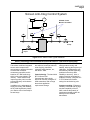
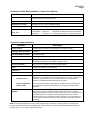
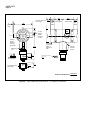
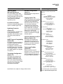
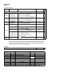
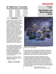
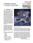
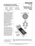
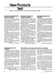
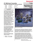
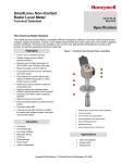
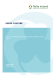
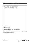
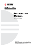
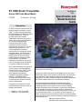
ST 3000 Smart Transmitter Series 900 Flush Mount Model STG93P 0-100 psig / 0-7 barg 34-ST-03-73 7/04 Specification and Model Selection Guide Introduction In 1983, Honeywell introduced the first Smart Pressure Transmitter― the ST 3000®. In 1989, Honeywell launched the first all digital, bi-directional protocol for smart field devices. Today, its ST 3000 Series 900 Pressure Transmitters continue to bring proven “smart” technology to a wide spectrum of measurement applications. Honeywell offers the STG93P transmitter for direct insertion in processes with the use of a 1” sleeve, welded into the process line. The primary application is pressure measurement in the head box of pulp and paper plants. The flush mount capability eliminates the possibility of clogging while the insertion design makes transmitter change out rapid and trouble-free. The STG93P transmitter is available in ranges from 0-5 to 0-100 psig and can be installed in a variety of hazardous locations. All ST 3000 transmitters can provide a 4-20 mA output, Honeywell Digitally Enhanced (DE) output, HART* output, or FOUNDATION™ Fieldbus output. When digitally integrated with Honeywell’s Process Knowledge System™, EXPERION PKS™, ST 3000 instruments provide a more accurate process variable as well as advanced diagnostics. Honeywell’s cost-effective ST 3000 S900 transmitters lead the industry in reliability and stability: • • Stability = +/-0.01% per year Reliability = 470 years MTBF Figure 1—Series 900 Flush Mount Pressure Transmitters feature proven piezoresistive sensor technology. The devices provide comprehensive self-diagnostics to help users maintain high uptime, meet regulatory requirements, and attain high quality standards. S900 transmitters allow smart performance at analog prices. Accurate, reliable and stable, Series 900 transmitters offer greater turndown ratio than conventional transmitters. "Honeywell transmitters operating in the digital mode using Honeywell's Digitally Enhanced (DE) protocol make diagnostics available right at the control system's human interface. Equally important, transmitter status information is continuously displayed to alert the operator immediately of a fault condition. Because the process variable (PV) status transmission precedes the PV value, we are guaranteed that a bad PV is not used in a control algorithm. In addition, bi-directional communication provides for remote transmitter configuration directly from the human interface, enabling management of the complete loop.” Maureen Atchison, DuPont Site Electrical & Instrumentation Leader 34-ST-03-73 Page 2 Description The ST 3000 transmitter can replace any 4 to 20 mA output transmitter in use today and operates over a standard two-wire system. The measuring means is a piezoresistive sensor, which actually contains three sensors in one. It contains a differential pressure sensor, a temperature sensor, and a static pressure sensor. Features • Choice of linear or square root output conformity is a simple configuration selection. • Direct digital integration with Experion PKS and other control systems provides local measurement accuracy to the system level without adding typical A/D and D/A converter inaccuracies. • Unique piezoresistive sensor automatically compensates input for temperature and static pressure.Added “smart” features include configuring lower and upper range values, simulating accurate analog output, and selecting preprogrammed engineering units for display. • Smart transmitter capabilities with local or remote interfacing means significant manpower efficiency improvements in commissioning, start-up, and ongoing maintenance functions. Microprocessor-based electronics provide higher span-turndown ratio, improved temperature and pressure compensation, and improved accuracy. The transmitter’s meter body and electronics housing resist shock, vibration, corrosion, and moisture. The electronics housing contains a compartment for the single-board electronics, which is isolated from an integral junction box. The single-board electronics is replaceable and interchangeable with any other ST 3000 Series 100 or Series 900 model transmitter. Like other Honeywell transmitters, the ST 3000 features two-way communication between the operator and the transmitter through our Smart Field Configurator (SFC). You can connect the SFC anywhere that you can access the transmitter signal lines. The SCT 3000 Smartline® Configuration Toolkit provides an easy way to configure instruments using a personal computer. The toolkit enables configuration of devices before shipping or installation. The SCT 3000 can operate in the offline mode to configure an unlimited number of devices. The database can then be loaded downline during commissioning. 34-ST-03-73 Page 3 Screen Anti-Clog Control System DFI Alarm STG93P Flush Mount Transmitter _ DPC FI PI _ PI FIC Accept Reject Figure 2 ST 3000 STG93P Typical Installation. Smart Technology Delivers Broad Benefits and Reduces Total Cost of Ownership The ST 3000 Flush Mount Transmitter combines integrated sensor and microprocessor technologies to produce the most accurate and consistent measurement possible, and is based on ST 3000 technology which is the most reliable in the industry. These features help improve product yield, increase process efficiency and enhance plant safety. In addition to the advantages of superior accuracy and reliability, the ST 3000 significantly lowers your lifetime cost of ownership in several ways: Installation - Wiring cost savings are achieved, as well as reduced costs of piping, manifolds, mounting, safety barriers, etc., with the ST 3000. Commissioning - The hand-held SFC III Smart Field Communicator lets a single technician remotely configure ST 3000 transmitters and re-range them when application requirements change. Maintenance - The ST 3000 offers greater accuracy and stability, reducing the frequency of calibration. Self-diagnostics can automatically indicate impending problems before they affect reliability or accuracy. Also, a single technician can diagnose problems remotely, using the SFC or TPS Global User Station, saving time and reducing cost. Inventory stocking - Enhanced reliability, combined with the high turndown capability of the ST 3000, reduces the quantity of instruments needed to stock as backups for the installed transmitters. 34-ST-03-73 Page 4 Digital Integration Links the ST 3000 to TPS for Greater Process Efficiency Digital Integration combines the functions of TPS system with the strengths of the ST 3000 to help achieve maximum productivity, by providing: Database security and integrity - PV Status transmission precedes the PV value, guaranteeing that a bad PV is not used in a control algorithm. Bidirectional communication and a common database for the system and the transmitter Data upload and download capability lowers transmitter installation costs. Single-window diagnostics for the transmitter (electronics and meter body) and loop - Remote troubleshooting reduces maintenance effort and expedites repairs. Automatic historization of all transmitter parameter changes - System maintenance log automatically provides audit trail of changes. Enhanced accuracy - Elimination of D/A and A/D converters improves signal accuracy. Digital Integration of the ST 3000 Transmitter with TPS allows you to combine advanced transmitter technology with our state-of-theart, process-connected controllers - the Process Manager, Advanced Process Manager and High Performance Process Manager. Digital Integration of the ST 3000 Transmitter with TPS improves the integrity of the process data measurements, letting you monitor process variability with greater accuracy. Accurate and more reliable data lets you implement advanced control strategies, providing greater bottom-line profits. 34-ST-03-73 Page 5 Specifications Operating Conditions – All Models Parameter Reference Condition Rated Condition Operative Limits °C °F °C °F °C °F Ambient Temperature 25±1 77±2 -15 to 65 5 to 149 -15 to 65 5 to 149 Process Interface Temp. 25±1 77±2 -15 to 65 5 to 149 -15 to 95* 5 to 203* Humidity %RH Vacuum Region Minimum Pressure mmHg absolute inH2O absolute 10 to 55 0 to 100 0 to 100 atmospheric atmospheric 300 150 2 (short term) † 1 (short term) † Supply Voltage, Current, and Load Resistance Voltage Range: Current Range: Load Resistance: Maximum Allowable Working Pressure (MAWP) STG93P = 100 psi, 5.1 bar Transportation and Storage °C -55 to 75 -67 to 167 10.8 to 42.4 Vdc at terminals 3.8 to 21.8 mA 0 to 1440 ohms (as shown in Figure 3) * Process temperatures above 65 °C (149 °F) require a 1:1 reduction in maximum ambient temperature. † Short term equals 2 hours at 70 °C (158 °F) 1440 1200 Loop Resistance (ohms) = Operating Area NOTE: A minimum of 250 0hms of loop resistance is necessary to support communications. Loop resistance equals barrier resistance plus wire resistance plus receiver resistance. Also 45 volt operation is permitted if not an intrinsically safe installation. 800 650 450 250 0 10.8 16.28 20.63 25 28.3 37.0 Operating Voltage (Vdc) NA NA 0 to 100 Units can withstand overpressure of 1.5X MAWP without damage. (ST 3000 products are rated to Maximum Allowable Working Pressure) °F 42.4 21012 Figure 3 —Supply Voltage and Loop Resistance Chart. 34-ST-03-73 Page 6 Performance Under Rated Conditions* - Model STG93P 0-100 psig (0-7 barg) Parameter Description Upper Range Limit** psig/barg 100 psig, 7 barg Minimum Span psig/barg 5 psig, 0.3 barg Turndown Ratio 20:1 Zero Elevation and Suppression No limit (except minimum span) from zero to 100% of URL. Accuracy In Analog Mode: ±0.10% of calibrated span or upper range value (URV), whichever is greater, - terminal based. (Reference – Includes combined For URV below reference point (25 psi), accuracy equals: effects of linearity, hysteresis, and 1.7 bar 25 psi repeatability) in % span or ±0.0125 + 0.0875 ±0.0125 + 0.0875 span bar span psi • Accuracy includes residual error after averaging successive readings. In Digital Mode: ±0.0875% of calibrated span or upper range value (URV), • For FOUNDATION Fieldbus use Digital Mode specifications. For HART use Analog Mode specifications. whichever is greater, - terminal based. For URV below reference point (25 psi), accuracy equals: 1.7 bar 25 psi in % span or ±0.0875 ±0.0875 span psi span bar Zero Temperature Effect per 28°C (50°F) In Analog Mode: ±0.40% of span. For URV below reference point (50 psi), effect equals: ±0.05 + 0.35 50 psi (span psi) 3.5 bar (span bar) or ±0.05 + 0.35 in % span In Digital Mode: ±0.35% of span. For URV below reference point (50 psi), effect equals: ±0.35 Combined Zero and Span Temperature Effect per 28°C (50°F) 50 psi (span psi) or ±0.35 3.5 bar (span bar) in % span In Analog Mode: ±0.50% of span. For URV below reference point (50 psi), effect equals: ±0.05 + 0.45 50 psi (span psi) or ±0.05 + 0.45 3.5 bar (span bar) in % span In Digital Mode: ±0.45% of span For URV below reference point (50 psi), effect equals: ±0.45 Stability 50 psi (span psi) or ±0.45 3.5 bar (span bar) in % span ±0.03% of URL per year * Performance specifications are based on reference conditions of 25°C (77°F), 10 to 55% RH, and Hastelloy C diaphragm. **Transmitter URL limit or maximum process connection rating, whichever is lower. 34-ST-03-73 Page 7 Performance Under Rated Conditions - General for all Models Parameter Description Output (two-wire) Analog 4 to 20 mA or DE digital communications mode. Options available for FOUNDATION Fieldbus and HART protocol. Supply Voltage Effect 0.005% span per volt. Damping Time Constant Adjustable from 0 to 32 seconds digital damping. CE Conformity (Europe) 89/336/EEC, Electromagnetic Compatibility (EMC) Directive. Lightning Protection Option Leakage Current: 10 microamps max. @ 42.4 VDC, 93°C (Code “LP”) Impulse Rating: (rise/decay) 10/20 µ sec. 5,000 Amps (50 strikes) 10,000 Amps (20 strikes) 10/1000 µ sec. 250 Amps (1000 strikes) 500 Amps (400 strikes) Physical and Approval Bodies Parameter Description Process Interface See Model Selection Guide for Material Options for desired seal type. Diaphragm Materials (wetted) Hastelloy C Meter Body Materials (wetted) 316L Stainless Steel Fill Fluid Silicone (DC 200) Electronic Housing Epoxy-Polyester hybrid paint. Low copper-aluminum alloy. Meets NEMA type 4X (watertight) and designed to meet NEMA 7 (explosion proof). Process Connections Flush mount in 1” weld sleeve, with O-ring and locking bolt. Wiring Accepts up to 16 AWG (1.5 mm diameter). Dimensions See Figure 4. Net Weight 3.9 pounds (1.8 Kg) Approval Bodies - Hazardous Areas Approved as explosion proof and intrinsically safe for use in Class I, Division 1, Groups A, B, C, D locations, and nonincendive for Class I, Division 2, Groups A, B, C, D locations. Approved EEx ia IIC T4, T5, T6 and EEx d IIC T5, T6 per ATEX standards. See attached Model Selection Guide for options. - Canadian Registration Number (CRN) - All ST 3000 model designs, except STG19L, STG99L, STG170, STG180, have been registered in all provinces and territories in Canada and are marked CRN: 0F8914.5C. Pressure Equipment Directive (97/23/EC) The ST 3000 pressure transmitters listed in this Specification have no pressurized internal volume or have a pressurized internal volume rated less than 1,000 bar (14,500 psig) and/or have a maximum volume of less than 0.1 liter. Therefore, these transmitters are either; not subject to the essential requirements of the directive 97/23/EC (PED, Annex 1) and shall not have the CE mark, or the manufacturer has the free choice of a module when the CE mark is required for pressures > 200 bar (2,900 psig). NOTE: Pressure transmitters that are part of safety equipment for the protection of piping (systems) or vessel(s) from exceeding allowable pressure limits, (equipment with safety functions in accordance with Pressure Equipment Directive 97/23/EC article 1, 2.1.3), require separate examination. 34-ST-03-73 Page 8 Removal Clearance for All Caps 135 5.32 3 0.12 45.7 1.80 53.1 2.09 82.9 3.26 Without Meter 65.1 2.56 Without Meter With Meter 94.9 3.74 With Meter Plug 48.5 1.91 Optional Analog Meter on Terminal Block Side 172.5 6.79 Rotational Lock 17.78 0.7 Bolt, lock washer & O-ring (Std.) 30.5 1.2 ½” NPT Optional Adapter for M20 or ¾” NPT Optional Local Smart Meter on Electronics Side Optional External Ground 5/16-18 UNC-2A Thread 9.50 Long 0.375 26.29 1.035 1”Mounting Sleeve (Std. option) 17.78 0.7 25.4 1.0 26.64 1.049 Reference Dimensions: Figure 4 —Typical Mounting Dimensions for 1” Flush Mount Transmitter millimeters inches 34-ST-03-73 Page 9 Options Indicating Meter (ME and SM Options) The Smart Meter (option SM) provides an LCD display for both analog and digital output and can be configured to display 0 to 100% pressure in selected engineering units. Local Zero and Span A local zero and span adjustment option is available (option ZS). Lightning Protection (Option LP) A terminal block is available with circuitry that protects the transmitter from transient surges induced by nearby lightning strikes. HART Protocol Compatibility (Option HC) An optional electronics module is available for the Series 900 that provides HART Protocol compatibility. Transmitters with the HART Option are compatible with the AMS System. (Contact your AMS Supplier if an upgrade is required.) Transmitter Configuration (Option TC) The factory can configure the transmitter linear/square root extraction, damping time, LRV, URV, and mode (analog/digital), and enter an ID tag of up to eight characters and scratchpad information as specified. Indicator Configuration (Option CI) Provides custom configuration of Smart Meters. Tagging (Option TG) Up to 30 characters can be added on the stainless steel nameplate mounted on the transmitter’s electronics housing at no extra cost. Note that a separate nameplate on the meter body contains the serial number and body-related data. A stainless steel, wired-on tag with additional data of up to 4 lines of 28 characters is also available. The number of characters for tagging includes spaces. Custom Calibration and ID in Memory (Option CC) The factory can calibrate any range within the scope of the transmitter’s range and enter an ID tag of up to eight characters in the transmitter’s memory. FOUNDATION Fieldbus (Option FF) Equips transmitter with FF protocol for use in 31.25 kbit/s FF networks. See document 34-ST03-72 for additional information on ST 3000 Fieldbus transmitters. Ordering Information Contact your nearest Honeywell sales office, or In the U.S.: Honeywell Industrial Automation & Control 16404 North Black Canyon Hwy. Phoenix, AZ 85053 1-800-288-7491 In Canada: The Honeywell Centre 155 Gordon Baker Rd. North York, Ontario M2H 3N7 1-800-461-0013 In Latin America: Honeywell Inc. 480 Sawgrass Corporate Parkway, Suite 200 Sunrise, FL 33325 (954) 845-2600 In Europe and Africa: Honeywell S. A. Avenue du Bourget 1 1140 Brussels, Belgium In Eastern Europe: Honeywell Praha, s.r.o. Budejovicka 1 140 21 Prague 4, Czech Republic In the Middle East: Honeywell Middle East Ltd. Khalifa Street, Sheikh Faisal Building Abu Dhabi, U. A. E. In Asia: Honeywell Asia Pacific Inc. Honeywell Building, 17 Changi Business Park Central 1 Singapore 486073 Republic of Singapore In the Pacific: Honeywell Pty Ltd. 5 Thomas Holt Drive North Ryde NSW Australia 2113 (61 2) 9353 7000 In Japan: Honeywell K.K. 14-6 Shibaura 1-chrome Minato-ku, Tokyo, Japan 105-0023 Specifications are subject to change without notice. Or, visit Honeywell on the World Wide Web at: http://www.honeywell.com 34-ST-03-73 Page 10 34-ST-16-52 Issue 11 Instructions Select the desired key number. The arrow to the right marks the selection available. Make one selection from each Table, I and II, using the column below the proper arrow. Select as many Table III options as desired (if no options or approvals are desired, specify 9X). A () denotes unrestricted availability. A letter denotes restricted availability. Key Number ______ - I ___ II - III (Optional) _____ - _ _, _ _ KEY NUMBER IV + xxxx Selection Availab Span Gauge 0-5 to 0-100 psi 0-0.34 to 0-7 bar STG93P TABLE 1 METER BODY Materials of Construction Fill Process Head Process Interface 316 St. St. - Barrier Diaphragms Hastelloy C F__ Silicone _1_ 1" Slip-in with Locking Screw (Sleeve not provided) __1 00000 TABLE II No Selection 34-ST-03-73 Page 11 TABLE III - OPTIONS Selection Availabili None 00 HART Protocol compatible electronics FOUNDATION Fieldbus Communications HC FF y r b ME SM CI LZ ZS b Communication Options Indicating Meter Options Analog Meter (0-100 Even 0-10 Square Root) Smart Meter Custom Configuration of Smart Meter Local Zero Local Zero and Span m s x b Transmitter Housing & Electronics Options Lightning Protection Custom Calibration and I.D. in Memory Transmitter Configuration Write Protection 316 ST.ST. Electronics Housing - with M20 Conduit Connections 1/2" NPT to M20 316SS Conduit Adapter (BASEEFA EEx d IIC) 1/2" NPT to 3/4" NPT 316 SS Conduit Adapter Stainless Steel Housing with M20 to 1/2" NPT 316 SS Conduit Adapter (use for FM and CSA Approvals) Stainless Steel Customer Tag (4 lines, 28 characters per line) Stainless Steel Customer Tag (Blank) End Cap Live Circuit Warning Label in Spanish (only with ATEX 3D) End Cap Live Circuit Warning Label in Portuguese (only with ATEX 3D) End Cap Live Circuit Warning Label in Italian (only with ATEX 3D) End Cap Live Circuit Warning Label in German (only with ATEX 3D) LP CC TC WP SH A1 A2 A3 n n u i b TG TB SP PG TL GE b CF MS F1 F3 F5 F6 MT W1 W2 W3 W4 a a b a a Meter Body Options Calibration Fixture (with 1/4" NPT Port for Pressure Source) 316L SS Mounting Sleeve (requires customer installation to process) Services/Certificates/Marine Type Approval Options Calibration Test Report and Certificate of Conformance (F3399) Certificate of Conformance (F3391) Certification of Origin (F0195)/"Attestation" if Amiens built FMEDA (SIL) Certificate Marine Type Approvals (DNV, ABS, BV & LR) b Warranty Options Additional Warranty - 1 year Additional Warranty - 2 years Additional Warranty - 3 years Additional Warranty - 4 years b 34-ST-03-73 Page 12 TABLE III - OPTIONS Approval Approval Type Location or Classification Body NO HAZARDOUS LOCATIONS APPROVALS Explosion Proof Class I, Div. 1, Groups A,B,C,D Factory Dust Ignition Proof Class II, III, Div. 1, Groups E,F,G Mutual Non-Incendive Class I, Div. 2, Groups A,B,C,D Intrinsically Safe Class I, II, III, Div. 1, Grps. A,B,C,D,E,F,G Explosion Proof Class I, Div. 1, Groups B,C,D CSA Dust Ignition Proof Class II, III, Div. 1, Groups E,F,G Intrinsically Safe Class I, II, III, Div. 1, Grps. A,B,C,D,E,F,G SA Intrinsically Safe Ex ia IIC T4 Non-Sparking Ex n IIC T6 (T4 with SM option) Intrinsically Safe, Zone Ex II 1G EEx ia IIC T4, T5,T6 0/1 Flameproof, Zone 1 Ex II 2G EEx d IIC T5, T6, Enclosure IP 66/67 Non-Sparking, Zone 2 Ex II 3G EEx nA, IIC T6 ATEX* (Honeywell). Enclosure IP 66/67 Multiple Marking** Ex II 1 G EEx ia IIC T4, T5, T6 Int. Safe, Zone 0/1, or Ex II 2 G EEx d IIC T5, T6 Flameproof, Zone 1, or Ex II 3 G EEx nA, IIC T6 (Honeywell) Non-Sparking, Zone 2 Enclosure IP 66/67 Ex d IIC T5 INMETRO Flameproof, Zone 1 (Brazil) 9X 1C 2J 4G 3S 3D 3N 3H 6D *See ATEX installation requirements in the ST 3000 User's Manual **The user must determine the type of protection required for installation of the equipment. The user shall then check the box [D] adjacent to the type of protection used on the equipment certification nameplate. Once a type of protection has been checked on the nameplate, the equipment shall not then be reinstalled using any of the other certification types. TABLE IV Factory Identification Restriction Letter a b i m n r XXXX Table Available only with Selection III 3D or 3H Table Not available with Selection Select only one option from this group III 1C or 2J SM III III III 1C, 2J TC, ME, 4G, 3S III FF, ME x III FF, SM s III F1D3, C1C3, 1C, 2J u 4G III y CE Conformity (Europe) 89/336/EEC, Electromagnetic Compatibility (EMC Directive). All options. b 34-ST-03-73 Page 13 This Page Intentionally Blank ST 3000 is a registered trademark of Honeywell International Inc. HART* is a trademark of the Hart Communication Foundation. FOUNDATION™ is a trademark of the Fieldbus Foundation. Industrial Measurement and Control Honeywell International Inc. 16404 North Black Canyon Highway Phoenix, Arizona 85053 Honeywell International Inc.