1
650 Series
Programmable Process
Controllers
Your GSE distributor is:
User's Guide
R
PART NUMBER: 39-10-31468
650 Series Programmable Process Controllers
R
650 Series
Programmable Process Controllers
Revision 3.0
May 1999
Part Number: 39-10-31468
176
User's Guide
175
650 Series Programmable Process Controllers
GSE SCALE SYSTEMS PUBLISHING GROUP
The User's Guide to the 650 Series Programmable
Process Controllers
Published by:
GSE Scale Systems
23900 Haggerty Road
Farmington Hills, MI 48335
U.S.A.
Information in this manual is subject to change without notice due
to correction or enhancement and does not represent a commitment
on the part of GSE, Inc. The information described in this manual
is solely the property of GSE, Inc. No part of this manual may be
reproduced or transmitted in any form or by any means, electronic
or mechanical, including photocopying and recording and sold for
any monetary figure without the express written permission of GSE.
This also includes both the software used for computer simulation
of GSE hardware and its firmware. Setup files that have not been
developed by GSE are neither the property nor the responsibility of
GSE. It is highly recommended that all setup files for the 650 series
to be backed on disk in ASCII text form.
Third Edition: May 1999
Part Number: 39-10-31468
174
i
User's Guide
ii
173
650 Series Programmable Process Controllers
Troubleshooting
57-66
W
Weighing increments
Weighing systems
Weighing units
19
6
13
The 650 series instruments come standard with a number of features
which makes it the most versatile and powerful system in its price
class. From the rugged load cells to the sophisticated electronics,
every effort was made in design and manufacture to provide you with
the most accurate and highest quality instrumentation.
Your GSE distributor will have done most of the work in setting up
your system to suit your application. This user's guide is intended to
be a reference tool for explaining the basic functions of day to day
operations. Any questions concerning the programming setup or
servicing of this product should be addressed to your GSE distributor.
For those who would like more information on installation and
program setup, a complete Technical Reference Manual is available
through your GSE distributor at a nominal cost.
If you have any questions or need assistance after first reading this
manual, please contact a GSE customer service representative at the
following number.
Your GSE distributor is:
172
iii
User's Guide
P111
P112
P118
P162
P181
P182
P183
P184
P200-P202
P204-P206
P206
P300-P309
P61100
P61104
P61105
P61106
P61107
Password
Permanent Mounting
Printing
62
45
34, 58
58
44
39-44
44
44
63-65
66
66
14,45, 47, 49
57, 61
36
36
36
36
29
22
51
R
Receive Communications
RS-232 Communications
52
52
S
Selectable Modes
Service
SmpSz
14, 18
65
44
T
Table Top Mounting
Temp Zero?
Time Parameter
Time and Date
Entering
Parameters
Viewing
Transmit Communications
iv
21
30, 33-34
55-56
55-56
56
55-56
55
51
171
650 Series Programmable Process Controllers
K
Keyboard
Model 650, 651
Model 653, 654
Keys, described
Standard
Alpha
11
11-12
11, 12
13-16
16-18
Phone: (248) 471-5880
Fax:
(248) 471-5844
Email: [email protected]
Internet: gse-inc.com
30-33
36
22
Research, Engineering, Manufacturing, Marketing, Sales, Technical
Training, Product Support, Product Service
3
21-28
21
22
21-22
38
GSE CANADA, INC.
P.O. Box 3591
617 East Lake Road
Airdrie, Alberta CANADA T4B 2B8
30
11-18
Distribution, Sales, Product Service
L
Last Zero?
Linearization Data Parameters
Load Cell Connections
GSE SCALE SYSTEMS, INC.
23900 Haggerty Road
Farmington Hills, MI 48335
U.S.A.
M
Model type indication
Mounting
Table-top
Permanent
Panel mount
Multi-Point Linearization
N
New Zero?
Numeric Keyboard
O
Only Zero?
Operating Modes
Options
30, 34-36
18
8-10
P
Phone: (403) 948-9921
Fax:
(403) 948-1449
Email: [email protected]
GSE Advanced Industrial Technologies GmbH
Hausinger Strasse 4
Langenfeld, Germany 40764
Phone: (011) 49 217-391-6399-0
Fax:
(011) 49 217-391-6399-9
Email: [email protected]
Distribution, Sales, Product Service
parameters
P110
57, 60-61
170
v
User's Guide
22 ReadNVErr
23 CheckNVPar
24 NVParFull!
25 DefltSetup
26 Bad Setup
27 RE-BOOT!
28 NoRAMAVAIL
29 PIN error
30 F.S.>MAX!
31 F.S.<.1mVv
32 ADD MORE!
33 ReCALReq’d
34 RES>25K!
35 RES>100K!
36 RES<100!
37 RES<1!!
99 Can’t Set
frmgXerror
ovrnXerror
prtyXerror
portXerror
tx abort
tx con’d
tx on hold
60
60
60
60
61
61
61
61
61
62
62
62
62
63
63
63
63
65
65
65
65
66
66
65
F
Features
Full Scale
Capacity
Response Time
6-8
18
29
19
H
Hardware Errors
59-60
I
Installation
vi
21-28
169
650 Series Programmable Process Controllers
Mode 31 Quantity Total
Mode 34 Piece Weight
Mode 35 Piece Weight x 1000
Mode 36 % Accuracy achieved
Mode 37 Last Sampled Amt
Negative Sampling
Parameter setup
Sampling
Custom Transmit
46
46
46
46
46
41
44-45
40-41
51
D
Date
Date Parameter
Default Transmission
Display
Double Accumulation Protection
55
55-56
51
11
49
E
Environmental Suitability
Error Messages
- - Cksumerror
- - EntryError
02 Underload!
03 Over-Load!
04 # > Dsply
05 Zero > Max.!
06 Tare>F.S.
07 Tare <0!
08 Check Conn.
10 Entry>Max!
11 WRONGCODE!
12 No Mods!
13 OutofRange
14 Must Keyin
15 Size >3999!
16 CHECK JUMPR
17 A/D BAD!
18 BufSzMax!
19 x06\x44\x61ta&Stop
20 Deflt A/D
21 WriteNVErr
22
57-65
63
63
57
57
57-58
58
58
58
58
58
58
59
59
59
59
59
60
60
60
60
60
168
Table of Contents
Page
Chapter 1 Introduction
.................................................
1.1
About This Manual
1.2
Controller Description
1.3
Common Weighing Applications
1.4
Features
1.5
Available Options
1.6
Display
1.7
Keypad
1.8
Alpha Keypad (Standard on model 657)
1.8.1
Keying In All Caps Data
1.8.2
Keying In Lower Case Data
1.8.3
Confirming Data Entry
1.8.4
Keying In ASCII Characters
1.8.5
Keying In a Percent Sign
1.8.6
Initiating a Command
1.8.7
Backspacing
1.8.8
Spacing
1.9
Operating Modes (Brief Explanation)
1.10
Specifications
1
Chapter 2 Installation Instructions ....................................
2.1
Positioning the Instrument
2.1.1
Table-Top Use
2.1.2
Panel Mount Use
2.1.3
Permanent Mounting
2.1.4
Environment Suitability
21
Chapter 3 Calibration Mode
....................................
3.1
Calibration Mode
3.2
Quick Calibration
3.2.1
New Zero
3.2.2
Last Zero
3.2.3
Temp Zero
3.2.4
Only Zero
3.2.5
Cal Reset
3.3
Save Calibration
29
Chapter 4 Counting Operations ......................................
4.1
About the Counting Mode
39
vii
User's Guide
Table of Contents
Alpha-Numeric String Entry
Auto-Enhance
keys used in
mode listing
Mode 30 Quantity
4.1.1
4.1.2
4.1.3
4.2
4.3
4.4
4.5
4.6
Counting mode (Key Operation)
Sampling to Determine a Pieceweight
Negative Sampling to Determine a
Pieceweight
Pieceweight Enhancement
Known Container Weight
Automatic Scale Select
Other 650 Series Features
Counting Mode Listing
Chapter 5 Accumulation Operations
......................
5.1
Accumu lation Operations
5.2
Performing Accumulations
5.3
Initializing Accumulation Totals
5.4
Preventing Double Accumulations
47
Chapter 6 Printing Operations
....................................
6.1
Performing a Print Operation
(COMM Ports and TTL Port connections)
51
Chapter 7 Variable or String Operations...............................
7.1
To View the Contents of a Variable
7.2
To Enter a Variable Value
7.3
To Store a Variable Entry
53
viii
Warning!
Any deviation from the original part design will void the
equipment warranty. This includes the cutting or replacement
of the power cable. Contact your GSE distributor before
attempting any modifications.
Warning!
Make sure the 650 series instrument is completely
disconnected from the power source before working on it.
Chapter 8 Time and Date (Clock Feature)...........................
55
8.1
Introduction
8.2
Viewing Time and Date
8.3
Entering New Time and Date
8.4
Adding Time and Date to the Custom Transmit
Chapter 9 Trouble-shooting
....................................
9.1
Error Messages (overview)
9.2
Operational Mode Error Messages
9.3
Setup Mode Error Messages
9.4
Hardware Problem Error Messages
9.5
Calibration Error Messages
9.6
General Error Messages
9.7
Miscellaneous Messages
9.8
Communications Error Messages
9.9
Trouble-Shooting
9.10
Service
53-54
44
11-16
46
30, 46
57
!
Any operation which involves going inside the enclosure
should be performed by qualified service personnel only!
Hazardous voltage is accessible within the enclosure.
AVERTISSEMENT!
Assurez-vous que le cordon d'alimentation secteur du
contrôleur de type 650 soit toujours débranché avant
d’effectuer un travail sur l'appareil.
Tout travail nécessitant l´ouverture de l'appareil devra être
effectué par du personnel qualifié après s’être assuré d'avoir
débranché l’alimentation secteur afin d'éviter tout contact avec
une charge électrique dangereuse provenant de l'intérieur de
l'instrument.
167
650 Series Programmable Process Controllers
INDEX
Table of Contents
Index
650 Series Indicators, descriptions
%Accy
.............................................................................
2
44
A
Accumulation
Parameter
performing
initializing accumulate totals
preventing double
AcDsp
AEnhn
Alpha-numeric entries
Applications, common
ASCII text backup
Auto-Enhance
47
47
47
48
49
45
44
11-18
6
3
42, 44
B
Backed on disk
Backspace
3
18
C
Calibration
Entering numeric values
Errors
Quick Cal
Re-Cal
Re-set
Re-zeroing
Cal Reset
Center Zero
Clock
Communications
Communications Errors
Continuous Print
Counting Mode
Achieved Accuracy
29
31
60
29
37-38
36
34-36
36-37
10, 13
55
51
63-65
51
39
44-45
166
ix
69
650 Series Programmable Process Controllers
100
User's Guide
165
User's Guide
650 Series Programmable Process Controllers
to the description of
parameter P206 for more
information.
tx abort
tx con'd
9.9
This occurs if the [CLR] key
is pressed when the tx on
hold error message is shown
or if P206 is set for abort and
the transmit buffer becomes
full.
This will appear briefly when
the handshake is re-asserted
after the tx on hold message
occurs.
Trouble-Shooting
DATA TRANSMISSION:
If a data transmission of any weightrelated numeric data such as Gross, Net or Tare, is sent as dashes, an
overload or underload (negative overload) condition was in effect.
Remove the cause of the overload (or underload) and repeat the
transmission. Check also the setup of parameters P204 and P206.
Chapter 1 Introduction
1.1
About This Manual
This User's Manual contains basic operating information on the
650 series controllers. A 650 Series Technical Reference Manual
is also available with all operating instructions, available options,
installation information, and technical information on system
setups (ie. macro Programming). This manual is available through
your GSE distributor.
The layout of the manual divides basic features of the 650 series
instruments into a chapter to allow for a brief but informative
explanation.
Information in this manual is subject to change without notice due
to correction or enhancement and does not represent a
commitment on the part of GSE, Inc. The information described
in this manual is solely the property of GSE, Inc. No part of this
manual may be reproduced or transmitted in any form or by any
means, electronic or mechanical, including photocopying and
recording and sold for any monetary figure without the express
DISPLAYED WEIGHT: If an overload or underload occurs due to an
electrical overstress (EOS) normally due to lightning or ESD discharge,
then press the [CLR] key. The message "wait 1" will appear for about 1
second. The A/D converter will then be reset and the system should
again be functional. If not, power down for a few seconds. If the
indicator still does not work properly after power-up, check the load cell
or platform wiring. If okay, permanent damage may have occurred,
most likely to the instrument amplifier.
9.10 Service
There are no user-serviceable items in the GSE 650 series! Service
must be performed by qualified service technicians only! Attempts to
service this instrument by unqualified personnel may void the warranty!
Figure 1-1.
164
Model 650
101
User's Guide
650 Series Programmable Process Controllers
9.8
Figure 1-2.
Model 653 with
Figure 1-4.
102
Communications Error Messages
prtyXerror
This indicates that the parity
of a received character did
not match the parity specified
in the Setup Mode, parameter
P202. This could also result
if the baud rate (P200) or the
number of data bits (P201)
are incorrect.
ovrnXerror
This indicates an over-run
error where an additional
character was received while
the receive buffer of the
650 was full, and thus
the extra received character
will be lost.
frmgXerror
Figure 1-3.
Model 655
Model 654
This indicates that the stop
bit of a received character did
not occur when it was
expected. This could be the
result of an incorrect baud
rate (P200), incorrect number
of data bits (P201), or
incorrect parity setting
(P202).
portX error
This indicates that the
650 did not check its
receive data register in time,
thus missing a character. If
this error should occur, please
notify your GSE distributor or the
factory. To prevent the
problem, try reducing the
baud rate (P200).
tx on hold
This will occur if a data
transmission is held up for
two seconds of more due to a
de-asserted handshake. Refer
163
User's Guide
650 Series Programmable Process Controllers
for a parameter which is not
field changeable, such as the
serial numbers or the audit
trail counter results in this
message.
- - Cksumerror
9.7
Upon each power-up, the
indicator tests the integrity of
its EPROM. If the result is
not correct this message is
displayed and the Indicator is
not usable. Verify that the
EPROM (U13) is installed
properly (no bent pins).
Miscellaneous Messages
EntryError
WhichTx#?
This error message is the
most commonly used. The
primary causes are entering a
value preceding a key (such
as [ZERO]) which is not
allowed, entering alpha data
for a numeric selection, or
entering a fractional value for
an entry which only accepts
whole numbers. This may
occur while in the Setup
Mode or one of the
operational mo des.
This message will appear when the instrument
is setup with more than one custom transmit
with parameter P991 set for “Prmpt” (Prompt)
and the [PRINT] key is pressed. The
“WhichTx#?” message is asking for a custom
transmit number to be entered. Keyin the
custom transmit desired and then press
[ENTER]. I.E. [2] [ENTER], for custom
transmit number 2.
written permission of GSE. This also includes both the software
used for computer simulation of GSE hardware and its firmware.
Setup files that have not been developed by GSE are neither the
property nor the responsibility of GSE. It is highly recommended
that all setup files for the model 650 to be backed on disk in ASCII
text form.
GSE Scale Systems offers technically-advanced, precision weighing
instruments for high-quality weighing systems. Among these
instruments are programmable process controllers. All GSE
controllers have innovative features that contribute to workplace
efficiency and productivity.
Within its 650 Series of products, GSE offers the following
programmable process controllers:
•
Model 650, shown in Figure 1-1;
•
Model 651, which is identical to the Model 650 except for the
display;
•
Model 653, shown in Figure 1-2;
•
Model 654, shown in Figure 1-3;
•
Model 655, shown in Figure 1-4;
•
Model 657, shown in Figure 1-5;
The Model 651 has a four-line-by-20-character alphanumeric
display in place of the standard display.
The Model 655 incorporates the standard VFD display and the 4line x 20-character prompting display.
Panel-mount versions of the Model 650 and Model 651 exclude the
back panel and tilt stand for special wall-cavity mounting.
A variety of options that enhance the 650 Series controllers are
available. The number of options that can be used (and, therefore,
the maximum capabilities) varies among the five models.
When integrated with a load cell, the 650 Series controllers form a
162
103
User's Guide
650 Series Programmable Process Controllers
complete weigh system. Load cells and scale platforms
manufactured by GSE and other companies can be used in these
systems. The 650 Series controllers convert the output signals from
the load cell or scale platform into a digital form that is displayed on
the controller display.
GSE 650 Series controllers can be customized for every type of
weighing application imaginable. Programmable software enables
the transmission of output data from the controller to a computer or
printer by way of an RS-232 port.
34 RES> 25K!
The current combination of
capacity P110 and increment
P111 result in a resolution
greater than 25,000
graduations. This is simply a
warning in case this was not
intended.
35 RES>100K!
The current combination of
capacity P110 and increment
P111 result in a resolution
greater than 100,000
graduations. This is not
allowed and as soon as any
key is pressed the instrument
will jump back into the setup
mode to parameter P110 to
verify the settings.
36 RES< 100!
The current combination of
capacity P110 and increment
P111 result in a resolution
less than 100 graduations.
This is simply a warning in
case this was not intended.
37 RES< 1 !!
The current combination of
capacity P110 and increment
P111 result in a resolution
less than 1 graduation (i.e.
the increment is greater than
capacity). This is not
allowed and as soon as any
key is pressed the instrument
will jump back into the Setup
Mode to parameter P110 to
verify the settings.
Accurate and durable, GSE 650 Series controllers are built to
provide years of quality weighing service even in the most
demanding industrial environments.
9.6
Gene ral Error Messages
99 Can't Set!
Figure 1-5.
An attempt to enter a value
Model 657
104
161
User's Guide
650 Series Programmable Process Controllers
the capacity, P110, and for
the calibration weight. If all
appears correct, refer to the
use of the information
parameter P61100, and
determine the output (in mv /
volt) of the connected load
cell.
31 F.S.<.1mVv
The entered calibration
weight, together with the
currently applied signal,
indicates that the full scale
signal will be less than the
allowed minimum of the
indicator. Verify the proper
entries for the capacity, P110,
and for the calibration
weight. If all appears correct,
refer to the use of the
information parameter,
P61100 and determine the
output (in mv / volt) of the connected
load cell.
32 ADD MORE!
33 ReCALReq'd
The applied weight during
calibration was less than
0.1% of capacity. More
weight than this is required.
Refer to P61100 if this is
incorrect.
The just completed
calibration is insufficient to
guarantee accurate results due
to either the cal weight being
less than 5% of capacity or
this was the first calibration
of this platform to this
indicator and therefore the
coarse gain was adjusted by
the indicator.
160
1.2
Controller Descriptions
Most apparently, the 650 Series controllers differ in appearance.
Table 1-1 provides dimensions for the five models.
Table 1-1.
Model
650 Series Controller Dimensions
Width
Height
Depth
650
11 in*
(279 mm)*
9 in*
(228 mm)
3.7 in*
(94 mm)
651
11 in*
(279 mm)*
9 in*
(228 mm)
3.7 in*
(94 mm)
653
16 in
(406.4 mm)
22.5 in**
(571.5 mm)**
9.28 in
(235.7 mm)
654
24 in
(609.6 mm)
32.5 in**
(825.5 mm)**
9.28 in
(235.7 mm)
655
11.07 in*
(281.20 mm)
12.16 in*
(308.9 mm)
4.70 in*
(119.4 mm)
657
16.60 in*
(421.6 mm)
12.10 in*
(307.3 mm)
4.93 in*
(125.2 mm)
mm =millimeter; in = inch
*Includes mounting stand.
**Includes mounting flange.
GSE Controller Models 650, 651 and 655 have a stainless steel
105
User's Guide
650 Series Programmable Process Controllers
enclosure for washdown environments. They come with a tilting
stand for so they can be positioned on a tabletop mounted to a wall.
The panel-mount version can be mo unted in a wall cavity or userprovided enclosure. As many as two optional 16-position I/O
boards can be installed on either the standard or panel-mount Model
650 and Model 651.
Model 653 and Model 654 have full metal enclosures. Each is
equipped with one 16-position I/O board. The Model 654 accepts
an optional 16-position I/O board, as well, expanding input and
output to 128 channels (Contact GSE). Optional prompting displays
and alphanumeric keypads can also be added to either the Model
653 or Model 654.
25 DefltSetup
been reset to
values.
26 Bad Setup
1.3
Common Weighing Applications
Typical weighing applications for GSE 650 Series controllers
include:
•
•
•
•
•
•
•
•
•
•
•
1.4
Small parts weighing
Large parts weighing
Parts counting
Vehicular truck loading (Truck in / Truck Out)
Tank weighing
Process industry weighing
Inventory control
Order picking
Floor and hopper scales control
Conveyor weigh systems control
Batching (mixing)
Features
The 650 Series controllers have the following standard features:
•
Easy-to-read vacuum fluorescent display with 0.75-in high
106
The stored data has a
checksum error. Check all
parameters or re-load
setup.
27 RE-BOOT!
The standard keypad on the Model 650 and Model 651 differs
slightly from the standard keypad for the Model 653 and Model
654.
Upon power-up the indicator
has not found the proper
codes. Therefore all
parameters have
factory default
up
28 NoRAMAVAIL
your
manufacturer.
The indicator cannot use the
EEPROM for data storage, so
it is attempting to poweragain to cure the problem.
The current setup requires
more RAM than is currently
installed. Either contact
dealer or the
29 PIN error
This message will appear on power-up or
setup if the E2 is corrupted in the
PIN section.
Check E2 for problems. The access
code is
defaulted to the
manufacturer (GSE) access
code.
Also check Error 11.
9.5
Calibration Error Messages
30 F.S.>MAX!
The entered calibration
weight, together with the
currently applied signal,
indicates that the
signal will be
allowed
full scale
greater than the
maximum of the
indicator. Verify that correct
entries have been made for
159
User's Guide
650 Series Programmable Process Controllers
9.4
Hardware Problem Error Messages
(19-mm high) digits (except Model 651)
•
Sealed elastomer keypad for superior protection against
chemicals and harsh environments
•
Capability to power as many as twelve 350-ohm load cells for
demanding applications, such as floor, truck, tank, and hopper
scales
•
Alternating Current (AC) power operation
•
Front Panel calibration and linearization execution
19 x06\x44\x61ta&Stop Certain combinations of protocol are not
available. The protocol
combination
selections are in P201,
P202 and P203. This
error occurs if an illegal
protocol combination
is selected. Refer to
chapter 8
Communications
in the technical reference
manual
for more information.
•
Full scale response time from 0.06 to 8 seconds
•
Selectable weighing units: pounds (lb), kilograms (kg), ounces
(oz), grams (g), and so on
•
Programmable RS-232 communications software
•
Programmable event timing
20 Deflt A/D
be
•
As many as 256 programmable setpoint events
•
Eight programmable I/O ports (as many as eight remote key
activations)
•
Storage and recall of VAR and specified data
•
999 user-defined variables: Strings, Floats, Unsigned Integers
and Integers
•
Remote Display support capability
•
Expandable memory for increased data storage
17 A/D BAD!
The processor has detected a problem with
the A/D chip. Contact your GSE
distributor.
18 BufSzMax!
the
to the
P208) exceed
displayed.
reference
GSE distributor.
21 WriteNVErr
22 ReadNVErr
The accumulative total buffer size for both
TX and RX buffers of all four COMM ports
on the 650 is 4096 bytes. If entries
“buffer size” parameters (P207this total, this error message will be
This message appears for 1 second. It will
displayed if the A/D calibration data gets
corrupted. Refer to the technical
manual or contact your
Error reading data from the
EEPROM. Possible U16 and U17
problem.
Error writing data to
the EEPROM.
Possible U16 and U17
problem.
23 CheckNVPar
Supplementary error message
for above errors.
•
As many as eight external relay module boards with as many as
16 modules per board (128 modules possible)
24 NVParFull!
The setup being attempted
requires more EEPROM than
is currently installed.
•
Battery-backed Time and Date Clock
158
107
User's Guide
650 Series Programmable Process Controllers
•
208 taking into consideration the 4%
overload.
Weighing increments of 1, 2, or 5 units, from .00001 to 500
Other features include:
9.3
•
Stainless Steel Enclosure for washdown environments (Models
650, 651, 655 and 657)
10 Entry>Max!
An entry was made which
had more characters than
allowed.
•
Versatile swivel stand for table or wall mounting (Models 650,
651, 655 and 657)
11 WRONGCODE!
•
Four-line by 20-character alphanumeric display (Model 651
and 655)
The incorrect access code
was entered, thus preventing
changes. In order to access
the Setup Mode, either the
proper code must be entered
or the [ENTER] key must
be pressed alone (to view
selections without making
changes).
12 No Mods!
The Setup Mode is being
accessed, but changes are
prevented.
13 OutOfRange
An entry made for a selection
was beyond the range of valid
choices.
14 Must Keyin
The choice for the current
parameter must be keyed in.
15 Size>3999!
The size of one of the Custom
Transmit setup has exceeded
the limit.
16 CHECK JUMPR
A programming operation
was attempted when the
program jumper is installed.
Installation of this jumper
will prohibit any
programming changes.
1.5
Setup Mode Error Messages
Available Options
Numerous hardware and software options that maximize the
capabilities and functions of the standard 650 Series controllers are
available. These options can be installed by your GSE distributor
when you order your controller, or they can be added later. All
options must be installed by your GSE distributor or a qualified
technician. Please do not return the controller to GSE for
installation of options.
Options are listed below in alphabetic order. Consult your GSE
products distributor for installation instructions.
16-Position I/O Board Option:
Board increases I/O capability to as many as 128 I/O circuits
(except Model 653).
8-Position I/O Board Option:
Board installs inside the instrument (Model 657 only).
4-Position I/O Board Option:
Boards (2 max) install inside instrument (Model 655 only)
Alpha Keypad Option:
Enables entry of alphabetic and ASCII characters.
Cable Options:
Scanner/Keyboard Adapter Cable
108
157
650 Series Programmable Process Controllers
03 Over-Load!
Input signal is greater than positive
full scale. Use same check as for
underload.
04 # > Dsply
Number to be displayed will not fit
within 6 digits. This will not
normally occur for the Gross, Net or
Tare Weights but may result while
displaying the accumulated totals if
the amount exceeds 999,999. Either
clear the totals or settle for only being
able to transmit the totals.
05 Zero> Max.!
An attempt was made to zero out more
than allowed per P118 selection. Use
the [TARE] key for subtracting off
container weights or if large dead-load
is always to be present, apply this
dead-load during the New Zero?
prompt during calibration to
permanently eliminate the offset.
06 Tare>F.S.!
07 Tare < 0 !
08 CheckConn.
Tare entry was greater than full scale.
Most likely the entered tare value was
incorrect.
Negative tare attempted, but not
allowed per P162. For auto-tares, the
GROSS Weight must be greater than
zero unless P162 is changed to allow
negative tares.
This message is displayed if the signal
into the A/D is +/- 2 times the Full
Scale signal. This is effectively taken
into consideration when the
information sent to the micro
processor from the A/D is +/ - twice
the allowable F.S. reading.
ie.
P110 F.S. = 100
User's Guide
Computer Cable
Printer (Eltron) Cable
RS-232 dot matrix printer cable
Database Memory Options:
Adds capability for creating database records, consisting of
fields, for data storage and retrieval; battery-backed SRAM
increases internal storage to 256K, 512K, 1M, or 2M
Multi-Scale Capabilities Option:
Enables the use of as many as three additional scale platforms
per controller.
Network Module:
Addressable RS-485 network card.
Panel Mount Version (Models 650 and 650 only)
Provides Model 650 standard electronics, keypad, and display
without the enclosure, tilt stand, and back panel for installation
in user-defined wall cavity or enclosure.
Peripherals Options:
Alphanumeric Keyboard (ASCII)
Prompting Vacuum Fluorescent Display Option:
An illuminating, four-line-by-20-character dot matrix display
for the additional display of prompting and status information.
Setup Parameter Memory Expansion Option:
8K memory chip can replace each of the two standard 2K
memory chips, increasing internal E2 memory from the
standard 4K to 16K maximum.
Severe Transient Voltage Suppression Option:
Protects the controller from power line transient damage.
Analog Output Option:
Up to 8 Analog Output cards can be added for analog output
signals of each scale value or any other independent variable.
Splash Guard Option:
A clear flexible vinyl cover for use in harsh environments. It
Error message will be displayed at +/-
156
109
User's Guide
650 Series Programmable Process Controllers
will keep the indicator well protected and looking like new.
Dura-Shield Option:
A clear weatherable film lexan. Adheres over keypad and
display. Recommend when high-pressure washdown,
petroleum distillates or harsh cleaning agents are present.
Technical Reference Manual:
A comprehensive manual for the advanced operation setups.
Includes many examples in each chapter, including macro,
database, communications and setpoint setups. Recommended
for anyone developing custom systems.
Simulation Software Package:
This software package is a tool used by programmers to
simulate actual application setups without the actual system
hardware. This package is used along with the Technical
Reference Manual by your local GSE distributor to provide you
with custom setups matched to your specific application needs.
If the time/date must be added to the custom transmit, add parameter
“11” to the custom transmit table. The custom transmits are located
starting at parameter P989. The first custom table includes the
manufacturer defaulted custom transmit shown in chapter 6, Print
Operations. The 650 has 249 other custom transmit tables for a total
of 250 custom printouts each with the possibility of having 3999
characters. The combination cannot exceed amount of E2 installed.
Chapter 9 Troubleshooting
This section of the User’s Manual provides information on error
messages, trouble-shooting and servicing the 650 series instruments.
Some information included in this section refers to parameters that are
not discussed in this manual. They are provided as a quick reference
to problems and solutions. Additional error messages and advanced
explanations of each error are in the technical refe rence manual.
Please refer to the technical reference manual or consult your GSE
distributor for additional information.
Technical Training Classes on all GSE instrumentation are offered
by GSE, Inc. Contact your GSE distributor for more information.
9.1
1.6
The following is a summary of all of the error messages within the
650. They are listed below in numerical order. The leading two
digits will appear on the numerical portion of the display, and the
message will appear on the two lines of dot matrix display. Following
each message is a summation of possible causes and probable remedy.
Display
Except for the Models 651 and 657, all 650 Series controllers have a
two-section vacuum fluorescent standard display. On the left side
of the display is a large, six-digit numeric area, and to the right is a
smaller, two-line-by-five-character dot matrix area. See Figure 1-7.
The large digit area displays numeric data, such as Gross Weight,
Net Weight or Tare Weight.
The dot matrix area has several purposes:
•
The first two characters on the upper line show the weighing
units of the displayed data.
•
The last three characters on the upper line show a CENTER
ZERO ( -->O<-- ) condition, at times.
•
The lower line of the dot matrix area specifies the type of data,
such as Gross, Net, Tare, etc.
110
9.2
Error Messages (overview)
Ope rational Mode Error Messages
02 UnderLoad!
Input signal less than negative full
scale. If this is due to excessive
loading, reduce the load. Otherwise
check the load cell connections. If a 4
wire load cell cable is being used,
check that the sense jumpers are in
place. Verify that the capacity
selection P110 is correct. Use the
information parameters, especially
P61100 to check the setup and input
signal.
155
User's Guide
650 Series Programmable Process Controllers
While in the Weigh Mode, the time and date can be displayed
simultaneously in the dot matrix and main displays. Press [11]
[SELECT] (This can also be accomplished by adding parameter “11”
in as one of the selectable modes in the P300 parameters). Contact
your local GSE Distributor for more information. The date is then
displayed on the large numeric display in the format "MO.DA.
YR" (or DA.MO.YR for international style) and the time is displayed
on the dot matrix display in the format "HH:MM:SS". The time may
be dis played in a 24 or 12 hour format with an "am" or "pm"
displayed as appropriate, depending on the setup of time -date.
The dot matrix area also displays specific messages during
controller operation and setup.
8.3
The standard keypad for the Models 650, 651, 655 and 657
controllers is shown in Figure 1-8 and for the Model 653 and Model
654 in Figure 1-9.
Entering New Time and Date
Access to changing the time and date easily from the keypad can be
set at P502. Make sure parameter P502 is set for “Enbld”. This will
select the operation to prompt the operator to enter a new date and
time . Press [11] [SELECT] to access the mode to enter the time and
date. The new date is entered by keying in "MO.DA.YR" (or "DA.
MO.YR" if international format was selected) followed by the
[ENTER] key. Month, day and year entries must be separated by
decimal points. Leading zeroes need not be entered. For example, if
you enter "4.1.96" and press [ENTER] the date is set to 04/01/96. If
the date is entered improperly, the prompt "try m.d.y" (or "try d.m.y"
for international format) is displayed. The word “Date” will then be
displayed. Press [ENTER] if the date is correct and move to the
“Time” setting mode.
The new time is entered by keying in "HH.MM.SS" in a 24 hour
format! Hours and minutes entries must be separated by a decimal
point. Seconds entry is optional, and if omitted, they are set to zero.
To specify seconds, it also must be separated from minutes by a
decimal point. Leading zeroes need not be entered. For example, if
you enter "8.9.45" and press [ENTER], the time will be set to
08:09:45; if you enter "15.02" and press [ENTER] the time is set to
15:02:00. If time is entered improperly, the prompt "try h.m.s" is
displayed. The word “ Time” will then be displayed. Press [ENTER]
if the time is correct.
8.4
On the Models 651 and 657, a four-line-by-20-character
alphanumeric display is substituted for the two-section vacuum
fluorescent display. See Figure 1-6.
1.7
Keypad
NOTE:
Figure 1-6.
Models 651 and 657 Display
Adding Time and Date to the Custom
Transmit
Figure 1-7.
154
Models 650, 653 and 654 Display
111
User's Guide
650 Series Programmable Process Controllers
entry length exceeds the setup size, the error message "Entry >> Max!"
is displayed briefly. The extra characters which surpass the setup size
are automatically eliminated and the remaining entry is then displayed.
Press [ENTER] to store the remaining entry.
7.3
To Store a Variable Entry
After completing your entry, press [ENTER] to store it as the
new variable.
Chapter 8
Time and Date (Clock Feature)
Figure 1-8.
Standard Keypad for the Model 650, 651 and 657 Controllers
8.1
Introduction
The 650 series includes a Time/Date feature which is battery backed.
This means that when the feature is used, the time and date does not
need to be entered every time the instrument is powered up. The
Time/Date feature permits printouts with time and day of the week
and the date in many possible formats. Consult with your local GSE
distributor or the 650 Series Technical Reference Manual for more
information on Time/Date configurations.
NOTE:
In the following discussion, HH is a 2 digit
representation for hours, MM is minutes, SS is
seconds, MO is month, DA is day and YR is year.
When the 650 is powered up, the time and date
clock is set to Jan 1, 1970, 00:00:00 am (the
UNIX computer standard).
A new Time and Date value can be keyed in by accessing the timedate setup parameters starting at Parameters P500 thru P504 (refer to
the 650 Series Technical Reference Manual or contact your local GSE
distributor). The Date is displayed in the large nume ric display in the
format "MO.DA.YR" (or DA.MO.YR if set for the international
style). The Time is displayed in the dot matrix display in the format
"HH.MM.SS".
Figure 1-9.
Standard Keypad for the Model 653 and 654 Controllers
112
8.2
Viewing Time and Date
153
User's Guide
650 Series Programmable Process Controllers
Variables may also be accessed by pressing [80] [.] [X] [SELECT] where
"X" is the number of the variable. If you try to select an ID that is not
available, the 650 will display "Invld Instn" (invalid instance).
In either case you may press [SELECT] at any time to exit the variable
viewing mode.
7.2
To Enter a Variable Value
If the variable value will be entirely numeric simply access the variable,
key in the numbers on the numeric keypad and press [ENTER]. The
entry you make here will overwrite any previously entered information.
Once an entry is started, an arrow symbol will appear in the upper line of
the dot matrix display. The entered digits will then appear on the second
line and will scroll across the lower then the upper line. You may enter up
to the maximum number of digits programmed in the Setup Mode. The
maximum number of characters is 63. Once an entry has been started, the
[F3?] key acts as a BACKSPACE key. If [F3?] is pressed with only one
character on the display, the entry mode would be canceled and the
previous display would appear.
The Model 650, 651 and 655 controllers have the following keys
that are not found on the Model 653 and Model 654 controllers:
• [CLR (No)]
• [ENTER (Yes)]
• [PRINT]
• [START]
• [STOP]
The Model 653 and Model 654 controllers have the following
keys that are not found on the Model 650 controller:
• [PRINT/ENTER]
• [CLR]
The rest of the keys are identical in label and function.
ZERO
The [CLR] key may be pressed at any point during entry, prior to pressing
the [ENTER] key, to clear the entered characters. Pressing [CLR] after
first accessing the variable will clear the existing value. To replace the
existing contents, simply enter new information as described previously.
If [F5?] is pressed after the string type variable is accessed, the current
variable data is copied into the entry buffer and the last character of the
existing variable entry would be shown in the last (bottom right) position
on the display. This lets you add characters to the end of an existing entry
or modify the last characters by using the backspace function.
Alphabetic and other characters may be entered at any point by pressing
the [F1• ] key while in the variable entry mode. An "A" will appear in
the display. At this point the [F1• ] and [F4?] keys are used to scroll up
and down through the entire standard ASCII character set. The [F3?] key
can be used to backspace, shifting all the previously entered data down
toward the lower right corner, with the last character being lost. Pressing
[F5?] would shift the entire previous entry toward the left thus making
room for a new character. This new character would be an "A". If the
152
Press [ZERO] to zero the current
quantity/weight reading. When the meter is at
Center Zero the international center-of-zero
indication will appear on the upper line of the dot
matrix display. This indication is a right and left
arrow pointing to a circle. If a Custom Unit’s
name is greater than 2 characters, the Center
Zero indication is not displayed. If in the
quantity mode pressing [ZERO] will set the
current mode to a gross zero quantity. If in the
weigh mode, pressing [ZERO] sets the current
mode to Gross Weight.
UNITS
Pressing the [UNITS] key in the quantity has no
effect. Pressing [UNITS] from the weigh mode
will toggle the displayed units through the
available selections. Converted units are
automatically rounded to the appropriate
increment. If the "lb/oz" units selection is used,
the first digits of the numeric display will read
the value for pounds, the last digits will read
ounces, and since the upper line of the dot matrix
display is used to show the units, there is no
center zero indication. As with other units
designations, the characters showing units will
blank out when motion is present.
SELECT
Pressing [SELECT] will toggle you through the
113
User's Guide
650 Series Programmable Process Controllers
Net Weight, Tare Weight and Gross Weight,
Acc. Net Wt., Acc. Gross Wt. or other enabled
operating modes. Refer to the Mode Selection
parameters, P300 - P309. Contact your GSE
distributor for more information.
TARE
Pressing [TARE] by itself will perform an
auto-tare. A Net Zero is then displayed. You can
enter a known Tare Weight into the 650 by
keying in the number and pressing [TARE].
In either case, the indicator will be placed in the
Net Mode, unless you are in the Tare Mode.
Auto-Tare and / or Keyboard Tare may be
disabled in the Setup Mode (P802). For
more information contact your GSE distributor.
ENTER/YES
Press [ENTER] key following certain numeric
entries. Doubles as a [YES] key for conditional
branching operations within macro routines.
PRINT
Press to send data to a printer, computer or other
device.
ID
[F1• ]
This key has multiple functions, entering ID's,
macro menu selection, database access and
specific macro access. The exa ct function of this
key depends on the selectable internal setup
(P806).
The [F1• ] key doubles as a direct access key to
invoke macro 1 or an Up arrow key. While
having accessed any mode or parameter which
requires a character entry, the [F1• ] key will
scroll through a set of ASCII characters. As
entries are keyed into the entry buffer, the
[ENTER] key will complete the entry.
[F2]
The [F2] key has direct access to invoke
macro 2.
[F3?]
The [F3?] key doubles as a direct access key to
invoke macro 3 or a Left arrow key. While
114
Chapter 7
Variable or String Operations
The 650 series has 999 variables which may be defined as strings, floats,
integers or unsigned integers. These variables may be used to store such
things as part numbers and descriptions, bin locations or any other
alphanumeric item that will be used during operation. The 650 is
manufacturer defaulted with no variables pre-programmed. If a variable is
defined as a string type the maximum ID size can be set to 63 characters.
Entering information into a variable is explained in the following sections.
7.1
To View the Contents of a Variable
To access a variable while in the Weigh Mode, press [X] [ID] where “X”
is the number of the variable. The five segments of the lower portion dot
matrix display will read "V#001". This is the name of variable number 1
(This name can be custom named to your application). The upper line of
the dot matrix display will show the first five characters of a string
contents. If the variable was defined as a float, integer or unsigned integer
type the value will be shown on the main display.
151
User's Guide
650 Series Programmable Process Controllers
Although all transmissions are usually initiated by pressing the
[PRINT] key, exceptions in the setup will allow for remote key
printing and continuous printing. The continuous print will transmit
the custom programmed information each time the display is updated.
This feature is particularly useful with a remote display or an
interface with a computer that is monitoring a process.
If the receiving device (printer, display or computer) goes off line, is
powered down or for any other reason cannot receive the data being
sent, the message "Tx On Hold" will appear for a few seconds. Press
[CLR] to abort the transmission. If this situation happens while using
the continuous print feature, the transmission is suspended, but can be
resumed by pressing the [PRINT] key.
having accessed any mode or parameter which
requires a character entry, the [F3?] key will
backup to the previous character. As entries are
keyed into the entry buffer, the [ENTER] key
will complete the entry.
[F4?]
[F5?]
The 650 series is manufacturer defaulted to transmit the custom
transmit (previously shown) out COM Port 1, On Request (PRINT
key), Motion Inhibited. These selections are made at parameters
P980 thru P998.
Connecting a printer or computer cable to the 650 requires entering
the enclosure. These connections should be made by a certified
technician. Entering the 650 enclosure may void the warranty.
Contact your GSE distributor or refer to the technical reference
manual if this defaulted configuration does not meet the application
requirements. The full programmability of the 650 series as defined
in its technical reference manual makes it easy to meet virtually all
serial RS232-C communications requirements.
Additional internal connections other than COMM 1 include serial bidirectional COMM Ports 2, 3 and 4. Note that COMM Port 4 is
manufacturer configured as a serial TTL bi-directional port. Also
note that COMM 4 can be field configured as a serial RS232-C bidirectional port. Refer to the 650 Technical Reference Manual for
more information.
CAUTION!
Any operation which involves going inside the enclosure should
be performed by qualified service personnel only! Hazardous
voltage is accessible within the enclosure.
150
The [F4?] key doubles as a direct access key to
invoke macro 4 or a Down arrow key. While
having accessed any mode or parameter which
requires a character entry, the [F4?] key or
Down Arrow will scroll through the character set
in reverse. As entries are keyed into the entry
buffer, the [ENTER] key will complete the entry.
The [F5?] key doubles as a direct access key to
invoke macro 5 or a Right arrow key. While
having accessed any mode or parameter which
requires a character entry, The [F5?] key or
Right Arrow when pressed will move over to the
next character. As entries are keyed into the entry
buffer, the [ENTER] key will complete the entry.
When in the weigh or quantity modes, the unit is ready to accept a
structured ASCII file for custom setups. The custom setup is
received through one of the units bi-directional communications
ports on an internal connector of the 650 identified as (J5).
START
The [START] key will invoke macro 6.
STOP
The [STOP] key will invoke macro 7.
SETUP
The [SETUP] key will invoke macro 8.
0 thru 9 & .
Press these keys to enter 0 thru 9. Press the
decimal point key to establish a decimal point.
CLR
Press this key to clear a numeric entry mistake
prior to entering it into memory.
SCALE SELECT
Pressing [SCALE SELECT] will toggle
through all the enabled scale inputs.
115
User's Guide
650 Series Programmable Process Controllers
1.8
Alpha Keypad (Standard on Model 657)
The TTL alpha keypad is a standard feature on the model 657.
This keypad is an option for any 650 series instrument. It
interfaces easily on COM 4 set for TTL interface. The models 653
and 654 have been designed to accommodate this keypad in their
enclosure.
1.8.1 Keying In All Caps Data
To key in alphabetic information in an all caps format, simply
press the desired alphabetic keys. View the display.
Chapter 6
Printing Operations
6.1
Performing a Print Operation
Pressing the [PRINT] key will transmit the information in the
custom transmit. The 650 series has 250 custom transmits. The
custom transmit refers to a table that can be customized to your
application. The 650 series is configured with a manufacturer
default transmission shown below. If this is not the desired
transmission format, contact your GSE distributor for custom
modifications to the transmit format or refer to the 650 Series
Technical Reference Manual.
Figure 1-10.
Alpha-numeric Keypad for Model 657
116
9876.54 lbs Gross Wt.
12.34 lbs Tare Wt.
9864.20 lbs Net Wt.
149
650 Series Programmable Process Controllers
User's Guide
1.8.2 Keying In Lower Case Data
To enter alphabetic information in a lower case format, hold in the
lower case shift key in the bottom left corner of the Alpha Keypad
along with the desired alphabetic keys. See Figure 1-10. View the
display.
1.8.3 Confirming Data Entry
When the data you have keyed in appears on the display to your
satisfaction, press the ENTER key ( ) located in the lower right
8
corner of the Alpha Keypad. (See Figure 1-10.) This action
transmits the Enter command (%e) to the Process Controller.
1.8.4 Keying In ASCII Characters
To enter non-alphabetic ASCII characters, press the “2nd” key (on
the bottom row of keys) along with the desired character, which
appears in the lower, gray-shaded portion of the Alpha Keypad
keys. See Figure 1-10.
1.8.5 Keying In a Percent Sign
Table 5-1.
Accumulation Mode Numbers
Mode Number
Description
3
Gross Total (GrTOT)
6
Net Total (GrTOT)
To key in a percent sign (%), press the “%” key. (See Figure 110.) This action transmits two percent sign signals to the Process
Controller, but creates just one percent sign on the display.
Example: Key in “2 % Q” to insert the command to send custom
transmit #2.
1.8.6 Initiating a Command
9
Accumulation Counter (# Accum)
31
Quantity Total (QtTOT)
148
To initiate a command, press the “2nd” key along with the percent
sign (%) key. (See Figure 1-10.) This action transmits one “%”
character to the Process Controller, enabling the next character you
press to represent a command.
Example: Key in “2[2nd]% Q” to send custom transmit #2
manually. (You press 2, then holding in the “2nd” key, you press
117
User's Guide
650 Series Programmable Process Controllers
%, and then you press Q).
1.8.7 Backspacing
To backspace, press the left arrow ( ¡ ) key. See Figure 1-10.
1.8.8 Spacing
To create a space in the text, press the right arrow ( ¢ ) key. See
Figure 1-10.
1.9
Operating Modes (Brief Explanation)
The 650 series controllers, provide five modes of operation
available to you: The Weighing mode, Counting mode, Calibration
mode, Accumulation mode and the Setup mode. The three
operational modes are described elsewhere in this manual.
The setup mode provides you access to the many groups of
Parameter registers physically resident within the unit. By entering
data in the Parameter registers, you can customize your weighing
operation to remember the different programming information for
your particular weighing application. Contact your local GSE
distributor for further information on this feature.
The Accumulation Registers may be reset to a new number. This
would permit you to enter a total from the previous day or shift to
continue the accumulation, or to reset the number to “0”. Simply
access the accumulation mode by keying in the single or two digit
mode number from table 5-1 and pressing [SELECT]. If the mode
is one of the pre-programmed selectable modes simply toggle to
the corresponding mode using the [SELECT] key only. Keyin the
desired reset value and press [ENTER]. You will then be
prompted to confirm the accumulation modification by a display of
MOD AC? for 1 second followed by ENTER =MOD. Press
[ENTER] to confirm the change or any other key to abort the
modification of the accumulation total.
The [CLR] key may be used to reset both the net and gross totals
to zero. The prompt CLEAR ACS? will appear briefly followed
by ENTER =CLR! Press [ENTER] to complete the clearing or
press any other key to abort the clear operation.
5.4
Preventing Double Accumulations
A setup parameter (P122) can help to prevent accidental double
accumulations. This parameter lets you choose a percent of
capacity that the gross weight must fall below before a second
accumulation can take place.
If an accumulate is attempted without first removing the last
accumulated weight, the message CLEAR WGHT! is displayed
briefly and the operation is aborted.
1.10 Specifications
Performance
•
•
•
•
•
•
•
•
Full Scale
Resolution
Display Update
A/D Conversion
Non-Linearity
Zero Track
Zero Range
Calibration
Selectable
100,000 displayed (+/-500,000 internal)
Selectable 0.05-20 seconds
60 Hz
0.005% of full scale (input dependent)
0.05-20.0 displayed divisions
Selectable from 0.01-100% of full scale
Selectable, 5 multi-point calibration for
linearization
118
147
User's Guide
650 Series Programmable Process Controllers
After an accumulation occurs, these values are frozen at their new
accumulate total values until the Gross Weight again falls below
the value set by parameter P122. Parameter P122 has several
selections of percentages of full scale value. The weight must fall
below this percentage of full scale before another accumulation is
allowed. At that time, these values again resume their active state.
This feature prevents double accumulations. A “CLEAR WGHT”
prompt appears to warn of such situations.
•
•
Division Size
Warranty
.00001 through 500
1 year
Electrical
•
•
Power Input 90-250 VAC, 50/60 Hz
Fuse 0.5 amp Slow-Blow
Load Cell Input
5.3
Initializing Accumulation Totals
Table 4-1.
•
•
•
•
•
Power Twelve 350-ohm cells
Signal Range 0.1 to 20 mV/V at full scale
Excitation 10 VDC or VAC, short circuit protected
Current 290 mA maximum
Communications
Counting Mode Parameter Numbers
Mode Number
Connections 4 lead or 6 lead with sense, jumper selectable
Description
•
•
•
30
Quantity
31
Quantity Total
•
•
RS-232 4 bi-directional serial ports
Output Up to 250 independent Custom Transmit tables for labels,
reports, transmitting control characters, etc.
Transmit OutputContinuous transmit, on request, motion inhibited, or
once per weighment
Baud Rate Selectable, 150-19,200 bits/sec, 38,400 between 650
Series controllers
Protocol Selectable
Display
34
Piece Weight
35
Piece Weight x 1000
36
Percentage Accuracy Achieved
•
•
•
•
•
•
Size Vacuum fluorescent, 0.75-inch digits display weight
Increments 1,2, 5, 10, 20, 50, 100, 500
Decimal Point Selectable
Bi-Polar Up to 99,999
Polarity "-" sign to left of most significant active digit
Status Indicator 10-character dot matrix prompting display
Weight and Construction
37
Last Sampled Amount
146
•
•
650/651, 6 lb/3 kg, Stainless Steel, NEMA 4 Type
653, 44 lb/20 kg, Mild Steel, NEMA 12 Type (Stainless Steel Available)
119
User's Guide
650 Series Programmable Process Controllers
•
•
654, 82 lb/37 kg, Mild Steel, NEMA 12 Type (Stainless Steel Available)
657, 16 lb/7 kg, Stainless Steel, NEMA 4 Type (Mild Steel Available)
For additional information about the 650 Series controllers, refer
to the 650 Series Programmable Process Controllers Technical
Reference Manual, GSE part number 39-10-31884.
Accumulation Operations
5.1
The 650 series offers three main memory registers into which
weighing data may be accumulated. The three registers are the
Gross Total, Net Total and the Quantity Total. There are a few
specific parameter selections built around the way in which
accumulations operate. These selections are made in the Setup
Mode. This chapter will explain how to do an accumulation after
the selections have been configured in the setup mode. Contact
your local GSE distributor for more information on the
accumulation parameter P122.
5.2
Chapter 2
Installation Instructions
This section of the user's manual outlines the basic installation of the
650 series instruments. Please take the time to review these important
guidelines and step-by-step procedures.
2.1
Positioning the Instrument
2.1.1
Table-Top Use
The Model 650, 651, 655 and 657 instruments have been designed with
a swivel bracket which lets you tilt the instrument face to any desired
angle. When the instrument is placed on a table, the non-slip rubber
feet prevent scratching and slipping across the surface when keys are
pressed.
2.1.2
Accumulation Operations
Performing Accumulations
First, enter the desired “accumulation mode” either by pressing the
[SELECT] key until one of the Accumulation Modes appears on
the display or keyin one of the accumulation parameters directly
shown in table 5-1 followed by the [SELECT] key. Once in an
accumulation mode, press [.] [ENTER] to add the displayed value
to the accumulated total. Accumulate operations are motion
delayed. If motion is occurring when an accumulation is
requested, the Mot'n Delay prompt is displayed until motion
ceases. If motion does not stop, press [CLR] to abort the
accumulation. There are six Accumulation Modes with
corresponding Mode Numbers as shown in table 5-1. The order of
appearance of these modes can be assigned when setting up
parameters P300 - P309. An accumulation mode can be added to
the default selectable modes. The factory default selectable modes
are Gross, Net, Tare, Quantity and Average Piece Weight. The
Quantity and Average Piece Weight will appear after a sample
routine is performed. Contact your local GSE distributor if it is
desired to add another mode of operation to the standard default
modes.
When an Accumulation is made, both the Gross and Net totals are
affected.
Panel Mount Use
The 650 and 651 are available in a panel mount version. The panel
cutout dimensions are L=9.25 x W=8.25. The unit is fully washdown
120
145
User's Guide
650 Series Programmable Process Controllers
of the current piece weight is shown on the display, above the "Qty"
indication, whenever the weight is not in motion. For example, after
performing a sample operation the 650 might show " 10. 98.3%
Qty". If this parameter is selected as "off" then the top line of the
alpha numeric display will only be used to indicate motion.
P185 PreSm
Pre-Sample: This parameter permits 5 choices; none, scale 1, scale
2, scale 3 and scale 4. If the parameter is set to a particular scale
number, if the operator presses the [ENTER] key while in the
quantity mode, the 650 will switch to Scale 1, 2, 3 or 4. If "none"
has been selected, the 650 will remain on the presently selected
scale.
P186 AftSm
After Sample: This parameter permits 5 choices; none, scale 1, scale
2, scale 3 and scale 4. If the parameter is set to a particular scale
number, after a sample is completed, the 650 will switch to Scale 1,
2, 3 or 4. If "none" has been selected, the 650 will remain on the
presently selected scale.
P187 SmpFl
Set the controller response time in terms of seconds for sample
operations.
once installed. The panel mount version functions identical to the table
top version. The only difference between the two package types is the
mechanical aspects of the enclosure and the positioning of the main
board and display. Refer to figures 2-1 and 2-2. Refer to the 650 Series
Technical Reference Manual for further panel mount version installation
procedures and available options.
2.1.3
Permanent Mounting
IMPORTANT!
The 650 series instruments do not include an on/off switch and
therefore must be installed near a power outlet socket which is easily
accessible, in keeping with UL/CSA approval requirements.
INFORMATION IMPORTANT!
Prendre note que les contrôleurs de serie 650 ne sont pas munis
d'interrupteurs "Marche / Arrêt". Par conséquent, il devront être
installés près d'une source d'alimentation secteur accessible pour
demeurer sous les exigences des normes UL/CSA.
P188 AcEnf
Enforces accuracy during the sample operation.
4.6
Counting Mode Listing
The [SELECT] key will advance the 650's mode to the next mode
as programmed in the setup mode P300 - P309. Alternatively,
keying a mode numb er then pressing [SELECT] will change the
650's current mode to be the mode whose number was keyed in.
The following six modes are Model 650 counting related. Refer to
table 4-1. Any one of these parameter numbers listed may be added
to a custom transmit printout.
Refer to the following line drawings is this chapter for mounting hole
dimensions.
2.1.4
Environment Suitability
The 650 series instruments are supplied in a sealed enclosure and may be
used in a washdown environment. Care must be taken to insure that the
AC power socket outlet is properly protected!
The keypad is made of silicon rubber. It may be cleaned periodically
with a soft damp non-abrasive cloth.
Chapter 5
144
121
650 Series Programmable Process Controllers
The display window is made from a polycarbonate material which may scratch
due to aggressive cleaning. Care must be taken to avoid such damage. For
models 650/651, GSE offers a Splash Guard transparent vinyl cover for added
protection. Contact your local GSE distributor for more information.
Chapter 3
Calibration Mode
3.1
Calibration Mode
The 650 series can be calibrated several ways. The following method
described is a quick calibration procedure and assumes that the necessary
parameters are selected before the actual calibration is performed. (ie. full
scale value, graduation size, etc.) These parameters will normally be set up by
your local GSE distributor.
NOTE:
The 650 series instruments are assembled in a sealed enclosure and may
be used in a washdown environment. Care must be taken to insure that
the AC power socket outlet is properly protected! Connections from the
load cell to the single channel input require gaining access to J1 inside
the sealed enclosure. Calibrating the unit requires entering the setup
mode and selecting the calibration parameters specific to your
application needs. Your local GSE distributor is available for this
operation. Physically gaining access to the unit may void the warranty.
Additional Connections:
Peripherals and options can be interfaced to the 650 series instruments by
means of connections internal the enclosure. Additional scale inputs can
be added to the system which require gaining access to the inside of the
unit. Refer to the technical reference manual or contact your local GSE
distributor. Gaining access to the inside of the unit may void the warranty.
122
User's Guide
the value entered here will affect the maximum number of pieces
which may be added and still allow the enhancement to take place.
P180 ASmpl
Auto Sample Accept: This parameter affects the sampling process.
If set for "off", the [ENTER] key must be pressed after the sample
is placed on the platform. However, when P180 is set to "on", the
650 will automatically accept the applied weight as the requested
sample size. The criteria for weight acceptance is that motion occur
and the weight is not at a center of zero condition.
P181 AEnhn
Auto-Enhance: Setting this parameter to "off" prevents the autoenhance feature from operating. The "on"selection allows the 650 to
auto-enhance the piece weight whenever the necessary criteria are
met.
182
SmpSz
Default Sample Size: This parameter specifies the sample amount
which the operator is prompted to add after the [ENTER] key is
pressed while in the quantity mode. Any whole number between 1
and 9999 may be entered here. 10 is the factory default.
P183 %Accy
Required Piece Weight Accuracy for Sample Acceptance: The value
entered here specifies minimum piece weight accuracy which must
be achieved in order for a sample to be accepted. If an applied
sample weight is insufficient to achieve the accuracy specified, the
operator will be prompted to add a specific number of parts in order
to achieve that accuracy. The choices available are no minimum
accuracy required (displayed as "none") or 90.0% to 99.96%, in
0.04% increments. Key in the desired percentage then [ENTER].
Entries will be rounded down to the next lower available accuracy
increment. Enter [0] for no accuracy requirement. This results in a
minimum sample weight of slightly greater than the zero-track
aperture, P112. Press [ENTER] to cycle through the available
choices starting at the previously selected choice.
P184 AcDsp
Accuracy Displayed: With this parameter set for "on", the accuracy
143
User's Guide
650 Series Programmable Process Controllers
scale 1, 2, 3 or 4 when the [ENTER] key is pressed while in the
quantity mode. The selection of “none” is also available and if
selected the 650 will remain on the presently selected scale. The
Pre-scale select would generally be used to select a smaller sampling
scale to establish an average piece weight. During operation, the
operator will press the [ENTER] key and the 650 will automatically
select the predetermined sample scale. The 650 will prompt the
operator with “add XX parts”. The “XX” is a GSE factory default
of 10 parts. The operator places the specified number of pieces on
the sample scale and again presses [ENTER]. The average piece
weight having been established, the 650 automatically selects the
appropriate “bulk” scale for higher capacity counting.
Parameter P186 can be set to select scale 1, 2, 3 or 4 automatically
after the sample routine. The selection of “none” is also available
and if selected the 650 will remain on the presently selected scale.
The Aft-scale select would generally be used to select the larger
scale on the 650 after the sample routine. An even larger floor bulk
scale for counting the remaining parts can also be selected. During
operation, after the sample routine is completed the Aft-scale will be
selected and placed in the quantity mode. Establish a tare value in
the standard fashion on the “Aft” scale if necessary.
4.5
Figure 2-1. Front and side views of Panel Mount
Other 650 Series Features
The following parameters may have been enabled by your GSE
distributor depending on your specific application.
P124 ErFac
Accuracy Error Factor: This parameter should normally be set to 1.
However this is intended to allow authorized GSE distributors to
adjust the 650 accuracy calculations to compensate for less than
ideal environment conditions. Conditions such as air currents,
widely varying temperature conditions, poor load cell performance,
and significant vibrations due to heavy machinery operating nearby
or poor support conditions can increase the sampling error of the
650. For example, entering a value of 2 would double the size of the
sample required to achieve a given accuracy. The entered value may
be between 0.1 and 20. Numbers less than one will increase the
calculated accuracy of the 650. Since the 650's decision as to when
it can and cannot enhance is based upon the it's calculated accuracy,
Figure 2-2.
142
Panel Mount version cutout dimensions
123
User's Guide
650 Series Programmable Process Controllers
Access the quantity mode.
3.2
Quick Calibration
Place an empty container on the platform. (optional).
The 650 series is calibrated as described below.
NOTE:
A certified weight is required to perform a
calibration. Serious inaccuracies could result
from using non-certified standards for
calibration.
1.
From the Weigh Mode press:
Press [ENTER]. The 650 tares the instrument to a zero net weight.
The display shows the current net weight and the prompt: "Add
10" (the actual number is programmable via setup parameter P182).
Place the specified number of parts on the scale.
Press [ENTER]. The 650 then calculates the piece weight of the
sample parts and momentarily displays the maximum number of
parts which may be added for a piece weight enhancement to occur.
The minimum achieved accuracy is then displayed.
If a greater accuracy is desired, add additional parts but not more
than the maximum enhanceable quantity.
As soon as motion ceases, the 650 will recalculate the piece weight
and then briefly display the new maximum number of pieces which
can be added and still accurately enhance the piece weight.
Repeat as many times as necessary to achieve the desired accuracy.
4.3
Known Container Weight
Place the full container of parts on the weigh platform.
At any point in the counting process, the known weight of a
container can be keyed in followed by the [TARE] key in order to
cancel the affect of the container. Make certain that the weighing
units of your entry are consistent with the current unit selection (lb,
kg, etc.)
4.4
Automatic Scale Select
(Where more than one weighing platform is present)
Figure 2-3.
Model 650 and 651 Dimensions
124
The 650 has the capability of automatically selecting a
predetermined scale before and after the a sample routine. One or
more multi-scale option cards must be installed for this feature to
work. Parameters P185 and P186 allow for selecting the Pre -scale
and Aft-scale. In other words, parameter P185 can be set to select
141
User's Guide
650 Series Programmable Process Controllers
the message Code 32 ADD MORE! is displayed briefly. This will
most often occur when the [ENTER] key is pressed without adding
any parts. If the parts were in fact placed on the scale, either the
parts are too light to count on that capacity platform or a much
larger quantity of parts must be hand counted in order to perform the
sample.
4.1.3
Negative Sampling to Determine a Piece
Weight
In order to perform a negative sample routine, access the quantity
mode, place a full or partially full container of parts on the scale and
press [ENTER].
The 650 will then perform an auto-tare resulting in a zero net
weight. The display will then prompt you to Add xx where the "xx"
is the sample quantity of parts (sample size) set by parameter P182.
In this case, the prompt Add xx actually means Take parts from the
container. Proceed to remove the requested number of parts, then
press the [ENTER] key. If the sample's total weight was sufficient,
the piece weight will be calculated and the sample quantity will be
displayed (-10 parts). Otherwise, you may be prompted to Take
additional parts. The exact prompts will depend on whether the autoenhance and/or minimum accuracy assurance features have been
enabled.
If the weight of the sample removed was un-detectable or barely
detectable then the message Code 32 ADD MORE! is displayed
briefly. This indicates that more weight must be removed adding to
the overall sample weight. This will most often occur when the
[ENTER] key is pressed without taking out any parts. If the parts
were in fact taken from the scale, either the parts are too light to
count on that capacity platform or a much larger quantity of parts
must be hand counted out in order to perform the sample.
4.2
Pieceweight Enhancement
Note:
The presence of this feature depends on the internal setup
of your 650. It is intended for the accurate counting of
extremely light parts.
140
Figure 2-4.
Model 653 Dimensions
125
User's Guide
650 Series Programmable Process Controllers
entry when the current mode is GROSS or GrTot, the stored tare
weight is assumed to be from a previous weighment and is cleared
out. Otherwise, any previous tare is assumed to be for the container
in use, so the tare is retained and the current net weight is used to
calculate the piece weight based on the entered sample size. This
allows for the situation where the tare weight of the container, if
any, remains consistent with what has been established. Here, you
can add the parts and then key in the number of parts.
NOTE:
The first method is recommended to avoid the possibility that
inappropriate tare weights may affect the piece weight calculation.
NOTE:
When the Quantity mode is accessed and the residing piece weight
value is “0.00”, the prompt “Must Sampl ” will be displayed. Press
the [ENTER] key to proceed with the sampling to determine a piece
weight (refer to section 4.1.2) or key in a piece weight value at P34.
4.1.2
Sampling to Determine a Piece Weight
Although the sampling process may be performed in a number of
ways, the recommended method is to first access the quantity mode,
then place an empty box or empty container on the scale platform,
and press [ENTER].
The 650 will then perform an auto-tare resulting in a zero net
weight. The display will then prompt you to Add xx, where the
"xx" is the sample quantity of parts (sample size) set by parameter
P182—the manufacturer default setting is 10 pieces. Add the
requested number of parts to the scale and press the [ENTER] key.
If the sample's total weight was sufficient, the piece weight will be
calculated and the sample quantity will be displayed. Otherwise,
you may be prompted to add additional parts. The exact prompts
will depend on whether the auto-enhance and/or minimum accuracy
assurance features have been enabled. The minimum amount of
weight required for the sample routine to meet the selected accuracy
requirements for the specified scale capacity is considered.
Figure 2-5.
Model 654 Dimensions
126
If the weight of the sample is un-detectable or barely detectable then
139
User's Guide
650 Series Programmable Process Controllers
Chapter 4
Counting Operations
4.1
About The Counting Mode
The front panel keys on the 650 series take on different functions
depending on which mode is selected. This chapter will define the
front panel key operation for the Counting mode. In order for the
650 to count parts, a sampling operation has to be performed to
establish the actual weight of one of the pieces to be counted.
4.1.1
Counting mode (Key Operation)
To activate the counting operation, the indicator must be in the
Quantity mode. To access the Quantity mode, you must place
parameter 30 in the selectable modes of instrument operation.
Simply press the [SELECT] key to step through all enabled modes
of instrument operation, including the Quantity mode. (Refer to
Chapter 24 of the 650 Series Technical Reference Manual.) You
can also access the Quantity mode directly when you press [30]
[SELECT].
Once you are in the Quantity mode, if you press the [ENTER] key
alone (without first making a numeric entry), the indicator will
perform an auto-tare, establishing a net zero as a starting point. The
current net weight and the prompt "Add XX" will be displayed.
("XX" is the default value set at parameter P182.)
If you add the specified number of parts—the default sample size set
at P182—press the [ENTER] key to confirm the sample. If the
number of parts you add is different from the default sample size set
at P182, first key in the actual number, then press the [ENTER]
key. The subsequent results depend on the selections made for the
auto-enhance and minimum accuracy selections. Refer to section
4.6 for more information.
If you make a numeric entry before you press the [ENTER] key, the
indicator will not perform an auto-tare. The entry is assumed to be
the number of parts already on the scale platform. If you make the
138
Figure 2-6.
Model 655 Dimensions
127
650 Series Programmable Process Controllers
User's Guide
prompt as described above and override the re-calibration
requirement. GSE recommends that you perform a re-calibration in
order to avoid any serious inaccuracy.
A variation of the calibration process is the linearization procedure.
Linearization is useful in improving the absolute accuracy of largecapacity systems, which often exhibit poor linearity. This feature is
documented in the 650 Series Technical Reference Manual.
Figure 2-7.
Model 657 Dimensions
128
137
User's Guide
650 Series Programmable Process Controllers
[100] [S ELECT] [5 4 3 2 1] [ID] [ENTER]
When reset, these parameters are adjusted to the lowest possible
values. Contact GSE regarding Information Parameters for a more
detailed explanation on the gain factors.
The 650 will briefly prompt you with the following:
QUICK CAL!
Normally, a Cal Reset is performed if the amplifier is locked in at an
extremely high gain factor and will not allow a new calibration to be
performed.
If multiple scales are enabled, the 650 will prompt you
with the following.
If an overload or underload condition exists while the controller is in
the Calibration Mode, press [CLR] to perform a Cal Reset. This has
the same effect as pressing [ENTER] at the Cal Reset prompt.
Keyin Scl #
2.
Once the Cal Reset is performed, the controller returns to the “New
Zero?” prompt. Press [SELECT] to toggle to the desired
calibration routine.
Following a Cal Reset, a re -calibration should be performed before
exiting the calibration or setup modes. The reset will not be saved
unless a re-calibration is performed and changes are saved.
3.3
Keyin the scale number being calibrated and press
[ENTER].
NOTE:
•
Press the [SELECT] key to toggle through the
available selections. and [ENTER] when the desired
selection is displayed.
•
Press [ENTER] to view a desired selection.
Save Calibration
The indicator will perform the calibration, display the value of the
calibration weight, and display the prompt, CAL OK? At this point,
you can check the accuracy of the calibration by weight without
leaving the Calibration mode.
A.
3.
The selections are as follows, starting with "New Zero?".
a) "New Zero?"
b) "Last Zero?"
c) "Temp Zero?"
d) "Only Zero?"
e) "Cal Reset"
If the calibration was accurate, press [ENTER].
The indicator will prompt you to save the new calibration
plus any other changes you made. Press [ENTER] to
save, and [ENTER] to exit.
B.
Pressing the [CLR] key at any point in the
calibration routine will back you up one step.
Refer to section 3.2.1
Refer to section 3.2.2
Refer to section 3.2.3
Refer to section 3.2.4
Refer to section 3.2.5
If the calibration is not accurate, press [CLR].
The indicator will return to the New Zero? prompt.
NOTE:
If the calibration weight is less than 5% of capacity or if there is a
large change in the calibration, the indicator will promp t, ReCal
Req'd. Press [ENTER] and you will be returned to the beginning of
the calibration selections, or press [CLR] to obtain the CAL OK?
136
3.2.1
“New Zero?”
“New Zero?” is the selection for establishing the first or a new
calibration.
If you select New Zero?, the controller displays the dead load
(which might not be in precise units) that is present on the scale. The
129
User's Guide
650 Series Programmable Process Controllers
controller assumes a “NO LOAD” condition.
You are prompted to remove any extraneous load. Remove the load,
and press [ENTER].
high, the controller displays an overload message. In such a
situation, you press [CLR]. The controller will reduce the
current instrument gain and return you to step 2 so you can restart the calibration.
As soon as you press [ENTER], a new zero is established. This is
reflected on the main display with the prompt “Adj’g Zero”
followed by the prompt “Keyin CalWt.”
The system will perform the calibration, display the value of the
calibration weight, and prompt CAL OK? Here, you can check
the accuracy of the calibration by weight without leaving the
Calibration Mode.
At this point, the controller is waiting for you to enter the actual
calibration value . Here, you place the calibration weight on the
platform, key in the weight value, and press [ENTER].
•
If the calibration was accurate, press [ENTER].
The controller will prompt you to save the new calibration
plus any other changes that were made. Press [ENTER] to
save, and [ENTER] to exit.
•
If the calibration is not accurate, press [CLR].
The controller will return to the New Zero? prompt.
Proceed as described in step 3 of this section.
NOTE:
If you key in a cal weight and press [ENTER] without adding
any weight since the last calibration weight, the controller will
prompt you to add CalWT. Add the weight and press [ENTER].
Entering Numeric Values:
Where appropriate, you can use the numeric keypad to enter
numeric values. If you make an error entering data, press [CLR]
before you press [ENTER].
The controller will perform the calibration, display the value of the
calibration weight, and prompt CAL OK? At this point, you can
check the accuracy of the calibration by weight without leaving the
Calibration Mode.
•
Press [ENTER] and return to step 3 of the procedure in Section
3.2, or press [CLR] to obtain the CAL OK? prompt and override
the re-calibration requirement.
GSE recommends that you perform a re-calibration in order to
avoid any serious inaccuracy.
If the calibration was accurate, press [ENTER].
The controller will prompt you to save the new calibration
plus any other changes you have made. Press [ENTER] to
save, and [ENTER] to exit.
•
NOTE:
If the calibration weight was less than 5% of capacity, or if there
was a large change in the calibration, the controller prompts
ReCal Req’d.
3.2.5
“Cal Reset”
“Cal Reset” adjusts the zero and gain factors of the amplifier on the
A/D. The parameters being adjusted include:
If the calibration is not accurate, press [CLR].
The controller will return to the New Zero? prompt.
NOTE:
If the calibration weight was less than 5% of capacity, or if
130
•
•
•
•
P61104 Coarse Zero
P61105 Fine Zero
P61106 Coarse Gain
P61107 Fine Gain
135
User's Guide
650 Series Programmable Process Controllers
Zero?” prompt.
there was a large change in the calibration, the controller
prompts ReCal Req’d.
The calibration units message and “Adj Zero!” displays for one
second, followed by the “Cal OK?” prompt.
Press [ENTER] and return to step 3 of the procedure in Section
3.2, or press [CLR] to obtain the CAL OK? prompt as described
above and override the re-calibration requirement.
Selecting “Only Zero?” can be useful in tank weighing applications
where the re-zero parameter (P118) is set very low in order to
prevent inadvertent re-zeroing. A build-up of sludge can be zeroed
out in this manner.
GSE recommends that you perform a re-calibration to avoid any
serious inaccuracy.
For example, with the connected scale platform cleared of any extra
weight, you can perform the following procedure.
3.2.2
1.
The “Last Zero?” selection is used to recalibrate the already
applied cal weight.
Access the calibration mode:
•
2.
3.
4.
5.
Using a remote keyboard , press:
[ID] [ENTER]
[SELECT] 5 4 3 2 1
“Last Zero?”
Press [SELECT] to toggle to the “Only Zero?” routine.
At the “Only Zero?” prompt, press [ENTER].
“Last Zero?” allows you to re-calibrate the controller without
removing the applied weight if, during a calibration check, the
calibration is found to be out of tolerance. This is especially
beneficial for large capacity applications, such as tank weighing on
remote platforms.
The displayed value zeroes out.
At the “Last Zero?” prompt, press [ENTER].
“Adj Zero!” is displayed briefly, followed by “CAL OK?”
Press [ENTER] to accept the newly established zero, or [CLR]
to re-do the calibration.
A scenario where you might select “Last Zero?” follows.
1.
A scale is to be checked for compliance with local weights and
measures regulation.
2.
The controller is zeroed by pressing the [ZERO] key.
3.
The necessary load is applied to verify accuracy.
4.
The weight indication is found to be out of tolerance.
5.
The calibration mode is accessed, using the Quick Cal or
normal method, while the calibration weight is still applied!
6.
At the “Last Zero?” prompt, the [ENTER] key is pressed.
7.
The controller briefly displays the message: “Using Last0”and
then “Units = xx” indicating the proper units for the keying in
of the calibration weight. The controller uses the zero
Follow the prompts to save all changes, and exit.
The calibration zero of the controller is now set to establish the
gross zero for the scale platform at the current input signal from
the platform.
NOTE:
If the keyed in weight exceeds Full Scale by +4% or falls below
0.1% of Full Scale, an error message is displayed.
If you forgot to add the calibration weight before you press
[ENTER], the controller prompts you to do so. Place the
calibration weight on the scale, and press [ENTER].
If an overload exists or the previously set instrument gain is too
134
131
User's Guide
650 Series Programmable Process Controllers
established by the last use of the [ZERO] key in the Weigh Mode
as the new calibration zero.
1.
Access the calibration mode:
•
8.
9.
At the prompt “Keyin CalWt” the operator keys in the currently
applied weight, such as 5 0 0 0 0 [ENTER]. The controller adjusts
the calibration parameters to bring the system into calibration.
After the prompt “Cal OK?,” the weight can be removed and reapplied, if necessary, to assure the inspector that the calibration has
been adjusted properly.
10. The inspector is satisfied with the calibration, so [ENTER] is
pressed to save the calibration.
[SELECT] 5 4 3 2 1
2.
Use the [SELECT] key to toggle to “Temp Zero?”
3.
At the “Temp Zero?” prompt, press [ENTER].
The displayed value should zero out.
4.
Apply the calibration weight to the tank.
5.
Key in the value of the calibration weight: for example, 1 0 0 0
[ENTER].
The numeric display should show the entered value.
6.
Remove the calibration weight from the tank.
11. At the prompts “Save Mods?” and “Enter = Save” are displayed,
[ENTER] is pressed to save the new calibration factors.
12. At the “Enter = Exit” prompt, [ENTER] is pressed again and the
controller returns to the weigh mode.
Using a remote keyboard , press:
[ID] [ENTER].
The display should return to zero.
3.2.3
“Temp Zero?”
“Temp Zero?” is used to recalibrate without establishing a new
zero.
In some applications you might want to perform a calibration without
removing the currently applied load. This is particularly useful in tank
weighing applications where it is both time-consuming and costly to
drain the tank being weighed.
During the calibration procedure, at the “Temp Zero?” prompt you
press [ENTER].
•
If the display reads as specified, at the “Cal OK?” prompt
press [ENTER].
•
To repeat the calibration process, press [CLR], and then
repeat steps 2 through 5.
7.
Save the newly determined calibration weight: At the “Enter =
Save” prompt, press [ENTER]
8.
To return to the weighing mode, at the “ENTER = EXIT” prompt,
press [ENTER].
The controller will return to the Weigh Mode.
This action causes the controller to zero the displayed weight
temporarily so additional weight can be added to assure system
calibration. The zero determined during the previous calibration is not
affected.
For example, where you have a tank containing an unknown amount of
material (such as on a remote scale) you would perform the following
procedure.
132
3.2.4
“Only Zero?”
“Only Zero?” is used for calibration re-zeroing.
If you only want to re-establish the calibration zero of the controller
without affecting the established gain, you press [ENTER] at the “Only
133


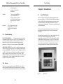
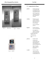

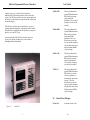


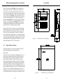


![[U4.53.21] Opérateur DYNA_TRAN_MODAL](http://vs1.manualzilla.com/store/data/006373829_1-51b1925756bb401edd53a987aa1cfc18-150x150.png)