1
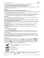
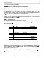
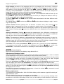
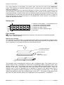
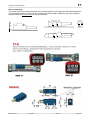
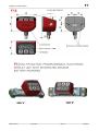
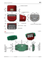
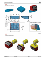
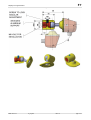
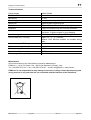
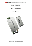
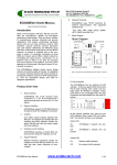
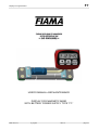
F7
Display for magnetic band
USER’S MANUAL AND MAINTENANCE
DISPLAY FOR MAGNETIC BAND
WITH BATTERY POWER SUPPLY TYPE “F7-“
Data: 04/11/13
F7_ing.doc
Rev:1.0
pag 1/12
F7
Display for magnetic band
Manual purpose
This manual has been designed by the Manufacturer to provide the necessary information
regarding the instrument F7_ to those who are authorized to carry out safely its installation,
maintenance, dismantling and disposal. All the necessary information for the buyers and planners
can be found in the Sales catalogue. Other than adopting good technical construction methods,
the information should be read carefully and strictly applied. Inobservance of this information could
cause risks for the health and safety of people and economical damage. This information,
provided by the Manufacturer in the original language(Italian) is also available in other languages
to satisfy legislative and/or commercial needs. This manual must be kept in good conditions by a
responsible person in an ideal place so that it is always available for consultation. In case this
manual is lost or deteriorates, a replacement should be requested directly from the manufacturer
quoting the manual’s code. This manual reflects the state of skill of the instrument at the time of
input on the market: however the manufacturer reserves the right to make changes, add or
improve the manual without giving any reason to hold the present manual inadequate.
Identification of the equipment
The identification plate represented is applied on the instrument.
To find out the identification code of the instrument, consult the sales catalogue.
Environmental conditions
Temperature setting: min. 0°C, max. + 50°C.
It is forbidden to use the instrument other than its specific use and in potentially explosive
conditions or where anti- explosive elements are used.
Storage
Here below are some references to be followed for the storage of the instrument.
Avoid environments with excessive humidity and those exposed to bad weather (avoid open
areas). Avoid putting the instrument directly on the ground. Store the instrument in its original
packing.
Conformity declaration and EC marking
The instrument answers to the following Communitarian Directives:
2004/108/EC Electromagnetic compatibility, with reference to general Rules EN61000-6-2
(immunity in industrial environment) and EN 61000-6-3 (emission in residential environment).
Maintenance
The instrument does not needs a particular maintenance except cleaning to do only with a soft
cloth dampen with ethylic alcohol or water. Do not use hydrocarbon solvents (petrol, diluents, etc.):
the using of these products could affect the proper functioning of the instrument.
Reparations should be done only and exclusively at the FIAMA technical assistance centre.
Calibrations and tests
It is advisable to calibrate the instrument periodically, once every working year.
To do the calibration, follow the calibration procedure indicated in the present manual.
Assistance request procedure
For any kind of technical assistance request, contact the sales department of the Manufacturer
directly indicating the information given on the identification plate, the number of hours used and
the type of defect.
Manufacturer’s responsibility
The manufacturer declines any responsibility in case of :
• Using the instrument contrary to the national safety and accident-prevention laws.
• Wrong installation, inobservance or wrong procedures of the instructions provided in the present
manual.
• Defective electrical power supply.
• Modifications or tampering.
• Operations carried out by untrained or unqualified staff.
The safety of the instrument also depends on the strict observance of the procedures indicated in
the manual: always operate the instrument in its functioning capacity and carry out a careful
routine maintenance.
Data: 04/11/13
F7_ing.doc
Rev:1.0
pag 2/12
F7
Display for magnetic band
• All phases of inspection and maintenance should be done by qualified staff.
• The configurations provided in the manual are the only ones permitted.
• Do not try to use it anyway contrary to the indications provided.
• The instructions in this manual do not substitute but accomplish the obligations of the current
legislation regarding the safety laws.
Installation
Before installing the instrument, read the following warnings:
a) Connect the instrument strictly following the instructions of the manual.
b) It is the responsibility of the user to check, before using, the correct settings of the parameters of
the instrument to avoid damage to persons or things.
c) The instrument CANNOT function in a dangerous environment (inflammable or explosive).
d) The unit has sensible parts to electrostatic charge, therefore the handling of the inner electronic
cards has to be carried out with appropriate care to avoid permanent damages.
Description
The F7 is a display unit with integrated position sensor, in combination with the P50 magnetic
band, is a complete system to measure linear movements.
The display has five digits plus sign (range from -99999 up to +99999). The digits are 7.5mm high
to allow excellent readability also at a distance.
It is possible to select the counting direction, the number of decimal places, and the units (mm or
inches). The displayed value can be corrected with a multiplication factor, with values between
0.001 and 99999.
The instrument can count in absolute mode or relative mode by pressing the corresponding
button. Also, it is possible to set a preset value which can be activated by pressing the
corresponding button.
The electronics are protected by a plastic housing which is robust, shock-resistant, and selfextinguishing.
Two versions of the F7 are available:
• F7-E with external sensor
• F7-I with integrated sensor
The display can be fixed quickly and easily using the two threaded holes on the back of the
housing or alternatively with the SM bracket support or the SF flanged support which can be
supplied optionally.
The unit is powered by a ½AA 3.6V battery which lasts approximately 4 years and when the
battery is almost exhausted, an icon will appear to advise the operator to substitute it. This does
not effect the configuration parameters and also the correct measurement is maintained if the
magnetic band is not moved during this operation.
Programming
and on the display appears , now
To step into the parameter programming press key
press 2 times key RESET and appear 4 zeroes, the first on the right is blinking, with keys (digit
increase) and
(digit selection), set out password 0273 and confirm with RESET. In case of
wrong set-out of password it goes out of the programming. The parameters that have to be set
can be run with key and in order of appearance they are:
0 +%
%.+
//
,/
/ value to be displayed for 10mm of sensor displacement,
number of decimal digits,
count direction,
keys opening mode
displacement of origin,
not used.
To enter into the modification of the selected parameter press two times RESET (one time displays
only the value) and with keys
and
set the wanted value to be confirmed with RESET.
Data: 04/11/13
F7_ing.doc
Rev:1.0
pag 3/12
F7
Display for magnetic band
To go out of the programming press
.
0 Value to be displayed for 10 mm of sensor displacement
This parameter together with the following allows the programming of the value on the display for
a certain displacement of the sensor. It means that is necessary to set the value which has to be
displayed corresponding to a displacement of the sensor on the magnetic band of 10mm.
The Factory value is VISUAL=10.0, which is the necessary value to read the displacement in
millimetres with decimal resolution.
The range allowed is from 0,0001 to 99999 with setting of decimal point position that is, after
will blink the decimal pinpoint and with
programming of the last digit on the left, pressing key
key it can be moved to the wanted position. Confirm with RESET.
+%Number of decimal digits
It is the number of decimal digits to visualize on the display, range allowed from 0 to 4.
Example: for every 10mm of linear displacement it is necessary to display 12.345 with only two
decimal places: Set 0=12,345
and +%=2
0
+%
//Keys opening mode
This parameter programmes the functions linked to the keys.
The value to set is a number of three digits so each key corresponds to a digit; the digit on the
right stands for setting of key RESET, the digit in the middle stands for key while the last digit on
the left stand for key
.
The values allowed are the following:
ENTER/RESET
VALUE
0
Not active
1
mm/inch conversion
2
3
Not active
Not active
Not active
abs/rel
measurement
Not active
Not active
4
Not active
Not active
5
6
Not active
Not active
Not active
Not active
7
Not active
Not active
8
Not active
Not active
Not active
Reset
Preset
Fast Preset
Change of origin
0,1,2
Offset
Fast Offset
Delayed reset *
(after 3s)
Delayed preset *
(after 3s)
* Delayed means that to activate the function (reset or preset), it is necessary to keep
ENTER/RESET pressed for approximately 3 s.
Reset: reset function of the displayed value; after pressing ENTER/RESET, the displayed value is
set to zero.
Preset: preset function of the displayed value; after pressing ENTER/RESET, the displayed value
becomes equal to the value in the 3U6Wparameter,
which can be set immediately after W$6W,
3U6W
(when the digit on the right is set to 2).
Fast Preset: the fast setting of the displayed value on the display; after pressing ENTER/RESET
and
3U6W appears and pressing 2 times ENTER/RESET it is possible to set the value directly (use
and then confirm with ENTER/RESET). This function is useful when the displayed value must be
corrected often.
Data: 04/11/13
F7_ing.doc
Rev:1.0
pag 4/12
F7
Display for magnetic band
Origin change (correction of the displayed value for tool changes): with this function 3 different
origins (0,1,2) can be set and with ENTER/RESET it is possible to switch from one origin to another.
After setting 4 in the first digit on the right of the W$6W,parameter,
3U6 will appear and after
W$6W,
pressing 2 times ENTER/RESET it is possible to set the nominal value for tool 0 (for example the
radius of cutter 0), which is then confirmed by pressing ENTER/RESET.
Now 3U6 will appear which is the nominal value for tool 1 (for example the radius of cutter 1): set
the correct value and confirm with ENTER/RESET.
Finally 3U6 will appear which is the nominal value for tool 2 (for example the radius of cutter 2):
set the correct value and confirm with ENTER/RESET.
In practice 3U6,3U6
3U6 3U6,
3U6 and 3U6 are the nominal values associated to the three different tools
which are used.
As a special case, if 3U6 is set to zero, 3U6 and 3U6 are the values to display in origin 1 and in
origin 2 respectively.
ABS/REL
function: Enables passing from an absolute to relative value; after pressing , the
displayed value is temporarily set to zero to measure a relative motion of the transducer. On the
display the REL icon indicates that the current display is relative to the reference point that has just
been created. Pressing again
causes the absolute value to be displayed and the ABS icon will
appear.
mm/inch conversion: Pressing
converts the measurement from millimeters to inches and
back. When in inch mode, the INCH icon will appear and the displayed value will have an additional
decimal place. When the parameter QG(&=4
QG(& the mm/inch conversion is not available.
Offset: This parameter is added to or subtracted from the displayed value to correct it in case, for
example, of a tool change or to compensate tool wear. After setting a positive offset value, the
displayed value will be the measured value plus the offset value. After setting a negative offset
value, the displayed value will be the measured value minus the offset value.
Fast Offset: After pressing ENTER/RESET, 2))6W appears and by pressing two times ENTER/RESET
it is possible to set directly the value to be displayed (use buttons
and confirm with
ENTER/RESET). This function is useful if it is necessary to correct often the displayed value.
%.+Count direction
Set out the count direction of the display, range allowed 0 or 1.
Adjustment of displayed value
After the installation of instrument on the machine and setting of all parameters, in order to visualize
on the display the correct value it is necessary to carry out the reset or preset.
Position the shaft in a point in which the correct measure that has to be visualized is known exactly
(for example the stroke end point) or measure the position in that point of the shaft. Program
parameter W$6W, with value 3 in the first digit on the right and exit programming.
appear, press again 2 times ENTER/RESET and set the correct
Now press ENTER/RESET and 3U6Wwill
3U6W
value to display, then confirm with ENTER/RESET. The display will now show the desired value.
If the required value is zero, instead of the preset function it is possible to use the reset function by
setting 1 in the first digit on the right in the W$6W,parameter
so that pressing ENTER/RESET will bring
W$6W,
the displayed value to zero.
Now that the instrument is adjusted, it is necessary to insert the desired W$6W,parameter
to avoid
W$6W,
accidental reset/preset of the displayed value.
Battery replacement
The instrument is supplied with a ½AA 3,6V lithium battery, which assures a typical functioning of
approximately 4 years.
When the battery runs down, an icon appears on the display.
To enter into the battery-holder it is necessary to remove the front cover by carefully inserting a flat
screwdriver on the sides. After taking off the cover, pull the battery out and substitute it with a new
Data: 04/11/13
F7_ing.doc
Rev:1.0
pag 5/12
F7
Display for magnetic band
one, paying attention to the polarity: the positive pole must face the side of the ENTER/RESET
button. The instrument is protected against inversion of polarity and wrong insertion, and in this
case will not switch on.
Removing the battery from the instrument switches it off after a few seconds: at this point do not
move the sensor to avoid losing the correct displayed value. As soon as the battery is fitted, the
instrument switches on with the same value on the display which was present at the moment when
it was switched off. If the sensor has not be moved, the displayed value will be correct. In case the
sensor moved when the instrument was off, to re-establish the correct measure it is necessary to
repeat the adjustment process.
Display icons
1
1. Indicator of low battery, it is activated when is
it necessary to change the battery.
2. Indicator of inches measurement.
3. Indicator for origin 1 and 2
4. Indicator of relative displayed value.
5. Not used.
2
3
4
5
Error message
RX(U:
RX(U the current displayed value passed the maximum value that can be visualized (possible
range: from –99999 to 99999).
Magnetic strip mounting
The magnetic strip P50 consists of a magnetized plastic ferrite strip with alternate magnetic poles
of 5 mm pitch, carried by a ferromagnetic steel strip. Mechanical protection of the plastic ferrite
strip is supplied by a non magnetic steel strip with thickness 0,2mm.
sensor side
non magnetic steel strip
(mechanical protection)
plastic ferrite strip
steel strip
(plastic ferrite support)
10
1,7
The magnetic strip is assembled by sticking it with a bi-adhesive tape. The surface has to be
smooth, clean and dry: is advisable to clean it with a degreasing product (isopropyl alcohol, ethyl
alcohol, solvents, etc). The magnetic strip has to be stuck holding the plastic ferrite side in the
direction of the sensor, which means the steel side leaned on the stand surface. Fixed the
magnetic strip, to keep off damages due to abrasions or grazes of the plastic ferrite strip, is
advisable the appliance (always bi-adhesive) of the non magnetic protection strip. The optimal
ambient temperature for stick the bi-adhesive tape is over 10°C. The maximum adherence of the
tape works out after 48 hours (about) of the application and is kept between –10 and 80°C.
Data: 04/11/13
F7_ing.doc
Rev:1.0
pag 6/12
F7
Display for magnetic band
Sensor mounting
The sensor has be mounted according to the following draw, and keeping the indicated tolerances.
For the optimal system functioning its is necessary that the distance between the sensor and the
magnetic band is not over 1mm of the useful stroke.
M AX 1
±3°
±3°
±3°
Data: 04/11/13
F7_ing.doc
Rev:1.0
pag 7/12
F7
Display for magnetic band
Data: 04/11/13
F7_ing.doc
Rev:1.0
pag 8/12
F7
Display for magnetic band
Data: 04/11/13
F7_ing.doc
Rev:1.0
pag 9/12
F7
Display for magnetic band
Data: 04/11/13
F7_ing.doc
Rev:1.0
pag 10/12
F7
Display for magnetic band
Data: 04/11/13
F7_ing.doc
Rev:1.0
pag 11/12
F7
Display for magnetic band
Technical features
Range display
-99999; 99999
Resolution
0,1mm
Max speed
2,5 m/s
Power supply
battery ½ AA, voltage 3,6V (lithium thionyl chloride)
Battery life
Typical 4 years continuous use
Display
High readability LCD with 7.5mm high digits
Keyboard
3 digits for programming and functions activation
Available functions
reset/preset, absolute/incremental value, mm/inch
conversion, 3 distinct origins for tool changing
Protection degree
IP54 display, IP67 sensor (for F7-E only)
Sensor cable (for F7-E only)
length: 0,5 – 1 – 3 – 5 meters;
Material: PUR Ø5,5mm suitable for movable wiring
cable
Sensor house (for F7-E only)
alluminium black
Gap sensor – magnetic strip
1mm max
Working temperature
0-50°C
Relative humidity
35-85%
Electromagnetic compatibility
EEC 2004/108
Manufacturer
All communications to the manufacturer should be addressed to:
FIAMA s.r.l., Via G. Di Vittorio, 5/A - 43016 San Pancrazio (Parma) - Italy
Tel. (+39) 0521.672.341 - Fax. (+39) 0521.672.537 – e-mail: [email protected] - www.fiama.it
FIAMA srl is not responsible for any damage to persons or things caused by tampering and
wrong use and in any case that are not consistent with the features of the instrument.
Data: 04/11/13
F7_ing.doc
Rev:1.0
pag 12/12