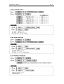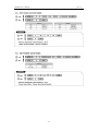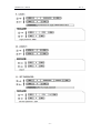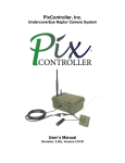
1
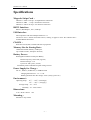
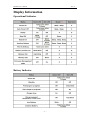
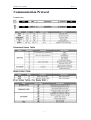
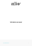
MiniDX4
Portable magstripe reader with rechargeable Battery
User's Manual
Revision A
2010-01-06
MiniDX4 User’s Manual
Rev. A
Standard Package:
a. MiniDX4
b. CD-ROM
c. Chain Sling
d. USB Cable
- 1 -
MiniDX4 User’s Manual
Rev. A
Connections
Specifications...................................................................................................................................... 3
Operational Description...................................................................................................................... 5
Card Data Format................................................................................................................................ 6
Communication Protocol.................................................................................................................... 7
FCC COMPLIANCE STATEMENT
This equipment has been tested and found to comply with the
limits for a Class A digital device, pursuant to Part 15 of the FCC
Rules. These limits are designed to provide reasonable protection
against harmful interference when the equipment is operated in a
commercial environment. This equipment generates, uses, and can
radiate radio frequency energy and, if not installed and used in
accordance with the instruction manual, may cause harmful
interference to radio communication.
Operation of this equipment in a residential area is likely to cause
harmful interference in which case the user will be required to
correct the interference at his own expense.
- 2 -
MiniDX4 User’s Manual
Rev. A
Specifications
Magnetic Stripe Card :
TRACK 1 / IATA / 210 bpi / 79 Alphanumeric Characters
TRACK 2 / ABA / 75 bpi / 40 Numeric Characters
TRACK 3 / Thrift / 210 bpi / 107 Numeric Characters
RS232 Interface :
RS232 , Half-Duplex , 8N1 , 9600 bps
USB Interface
Full compliance with the USB Specification V 1.1
The device uses a Virtual Serial Port Driver, making it appear to have the software like a
standard RS232 Serial Port.
CLOCK :
Real Time Clock (RTC) module and back-up capacitor
Memory Size for Storing Data :
CMOS Serial Flash Memory 512K bytes
Up to 2048 records ( 256 Bytes / Record )
Battery Power :
Rechargeable Lithium-ion Polymer Battery
Nominal Capacity: 250 mAH ( Typical )
Nominal Voltage: 3.7 V
Cycle Life: 300 cycles ( at least )
Low Battery Detect and Built-in Quick Charge Circuit
Power Supply for Charge :
DC 5V , 200mA ( for RS-232 ) or USB Powered
Charging duration time : 1.5 ~ 2.5 hr
Working duration time after charge : 48 hr ( always power on )
Environment :
Operating Temp : -0℃ ~ +60℃ ( Discharge )
-0℃ ~ +45℃ ( Charging )
Storage Temp : -10 ~ +65℃
Humidity : 10 ~ 90 % relative
Dimensions :
L 78 x W 20 x H 26.5
mm
Mounting :
Portable or Any surface
- 3 -
MiniDX4 User’s Manual
Rev. A
Display Information
Operational Indicator
Battery Indicator
- 4 -
MiniDX4 User’s Manual
Rev. A
Operational Description
1. Powered by Battery
For normal use, the unit is powered by battery. Push the Power Switch Button for about 1.5 seconds
to turn on the unit. Also push the Power Switch Button for about 1.5 seconds to turn off the unit.
After the unit is turned on, the power would be turned off automatically if there is no swiping a
card on the unit in 30 seconds. This means the unit would be turned off if no swiping a card again
in every 30 seconds after every card swiping. It would have Low Battery Detect/Warning indication
when the unit is powered by battery.
2. Powered by Cable
When the unit is connected with the PC through the communication Cable and the PC is running
MiniDX4 software and open the COM PORT for the unit, then the unit will be turned on in about
0.5 second by the PC through the RS-232 COM PORT. Then you can do the unit Setting,
Configuration or data downloading. When the software closes the COM PORT or exits, the power
turn off from the PC immediately. When powered by cable from PC, the Power Switch would have
no function and the unit would have no Low Battery Detect/Warning function.
3. Real Time Clock Setting
Before start using the unit, you must set the Real Time Clock (RTC) inside the unit to your local
time. If there is no battery for quite a while or it is powered by cable for quite a while this would
cause Real Time clock (RTC) malfunctioned due to no power supply. When put on the battery to
turn on the unit and the Red/Green LED take turns blinking, this means the RTC is malfunctioning
and you must do the RTC time setting before you use the unit.
4. Low Battery Detect
When powered by battery, it would have Low Battery Detect function. When the battery goes low,
the LED would flash green once every 2 second and you must charge battery immediately,
otherwise, the unit would shut down any time without pre-warning.
5. Charge Mode
There are three different charge modes for MiniDX4: low battery mode, real time mode and manual
charge mode. Low battery charge mode is used when the battery hits low voltage, it starts to be
charged automatically. Real time charge mode is whenever the MiniDX4 cable is connected to
USB or Power adapter, it would be charged immediately. Manual charge mode is the charge is
controlled by Demo software . User can use the software to start or stop charging.
6. Charge Status Indication
When MiniDX4 is in charge, Battery Status Indicator light show slow blink red that means the
battery is in the pre-charge. When Battery Status Indicator light turns to red, it means the battery is
in charge status. When Battery Status Indicator light turns to green, it means the charge is finished.
If the charge process has unusual situation, Battery Status Indicator light will show red fast blink. If
MiniDX4 cable is connected, and battery is not in charge, Battery Status Indicator light will turn off.
The default set mode is on low battery charge mode.
7. Memory Low Warning
Log database memory is almost full (>90%). Adding new records is still possible but you are
advised to free up the log database memory by uploading the data to the PC as soon as possible.
8. Memory Full Warning
Log database memory is full. You not be able to add any new records. Free the log database
memory by uploading the data to the PC.
9. Firmware Management mode (FMM)
FMM allows you to quickly upgrade your MiniDX4's internal firmware via com port and also
check validity of currently loaded firmware. Contact your dealer for most recent firmware upgrade
files.
- 5 -
MiniDX4 User’s Manual
Rev. A
Card Data Format
- 6 -
MiniDX4 User’s Manual
Rev. A
Communication Protocol
Packet Format
- 7 -
MiniDX4 User’s Manual
Rev. A
- 8 -
MiniDX4 User’s Manual
Rev. A
- 9 -
MiniDX4 User’s Manual
Rev. A
- 10 -
MiniDX4 User’s Manual
Rev. A
- 11 -
MiniDX4 User’s Manual
Rev. A
- 12 -
MiniDX4 User’s Manual
Rev. A
- 13 -
MiniDX4 User’s Manual
Rev. A
- 14 -
MiniDX4 User’s Manual
Rev. A
- 15 -