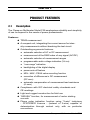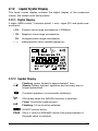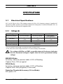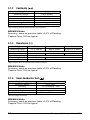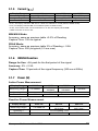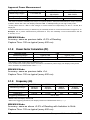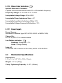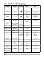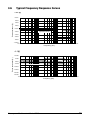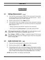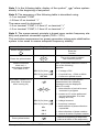
1
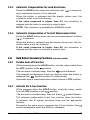
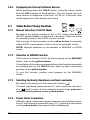
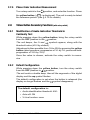
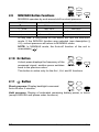
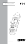
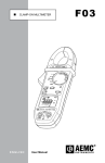
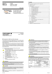
F09 CLAMP-ON MULTIMETER TRMS & POWER CLAMP METER ENGLISH User Manual F09 Statement of Compliance Chauvin Arnoux®, Inc. d.b.a. AEMC® Instruments certifies that this instrument has been calibrated using standards and instruments traceable to international standards. We guarantee that at the time of shipping your instrument has met its published specifications. An NIST traceable certificate may be requested at the time of purchase, or obtained by returning the instrument to our repair and calibration facility, for a nominal charge. The recommended calibration interval for this instrument is 12 months and begins on the date of receipt by the customer. For recalibration, please use our calibration services. Refer to our repair and calibration section at www.aemc.com. Serial #: _ ________________________________ Catalog #: 2129.50 Model #: F09 Please fill in the appropriate date as indicated: Date Received: __________________________________ Date Calibration Due: ________________________ Chauvin Arnoux®, Inc. d.b.a AEMC® Instruments www.aemc.com Table of Contents 1. INTRODUCTION................................................................................ 4 1.1 1.2 1.3 1.4 International Electrical Symbols.................................................4 Definition of Measurement Categories......................................5 Receiving Your Shipment...........................................................5 Ordering Information..................................................................5 1.4.1 Accessories and Replacement Parts.............................5 2. PRODUCT FEATURES....................................................................... 6 2.1 2.2 2.3 2.4 2.5 Description.................................................................................6 Model F09 Callouts....................................................................7 Rotary Switch Functions............................................................8 Command Buttons.....................................................................8 Hold Button Primary Functions..................................................8 2.5.1 Display Lock .................................................................8 2.5.2 Preselecting Min/Max Mode .........................................8 2.5.3 Automatic Compensation for Lead Resistance . ...........9 2.5.4 Automatic Compensation of Current Measurement Zero....9 2.6 Hold Button Secondary Functions (with rotary switch)..............9 2.6.1 Disable Auto-off Function . ............................................9 2.6.2 Activate the V-Live Function .........................................9 2.6.3 Displaying the Internal Software Version ....................10 2.7 Yellow Button Primary Functions........................................................10 2.7.1 Manual Selection of AC/DC Mode ..............................10 2.7.2 Selection of INRUSH Function ...................................10 2.7.3 Selecting Continuity, Resistance and Semi-conductor .10 2.7.4 Power Factor Calculation.............................................10 2.7.5 Phase Order Indication Measurement......................... 11 2.8 Yellow Button Secondary Functions (with rotary switch)......... 11 2.8.1 Modification of Audio Indication Threshold in............... 11 Continuity Test . ..................................................................11 2.8.2 Default Configuration................................................... 11 2.9 MIN/MAX Button Functions.....................................................12 2.10Hz Button.................................................................................12 2.11 Button................................................................................12 2.12Liquid Crystal Display..............................................................13 2.12.1 Digital Display..............................................................13 2.12.2 Symbol Display ...........................................................13 2.13Buzzer......................................................................................14 3. SPECIFICATIONS........................................................................... 15 3.2 3.3 3.4 3.5 3.6 3.1 Electrical Specifications...............................................15 3.1.1 Voltage (V)...................................................................15 3.1.2 Continuity ( )........................................... 16 3.1.3 Resistance (Ω).............................................................16 3.1.4 Semi-Conductor Test ( )...........................................16 )...............................................................17 3.1.5 Current ( 3.1.6 INRUSH Function........................................................17 3.1.7 Power (W)....................................................................17 3.1.8 Power Factor Calculation (PF).....................................18 3.1.9 Frequency (Hz)............................................................18 3.1.10 Phase Order Indication ( ).....................................19 3.1.11 Power Supply...............................................................19 Mechanical Specifications.......................................................19 Environmental Specifications...................................................20 Safety Specifications...............................................................20 Variations in Operating Range.................................................22 Typical Frequency Response Curves......................................23 4. OPERATION................................................................................... 24 4.1 Voltage Measurement - ( )..................................................24 4.2 Audio Continuity Test - ( )....................................................24 4.2.1 Lead Resistance Compensation (Ω zero)....................25 4.3 Resistance Measurement - (Ω)................................................25 4.4 Semi-Conductor Test - ( ).....................................................25 4.5 Current Measurements - ( )................................................26 4.5.1 Correction of Current Measurement Zero (DC Zero).......26 4.6 INRUSH Function....................................................................26 4.6.1 Implementation............................................................27 4.7 Power Measurement - (W).......................................................27 4.8 Power Factor Calculation - (PF)..............................................28 4.9 Frequency Measurement - (Hz)...............................................28 4.10Phase Order Indication - ( )...............................................28 5. MAINTENANCE.............................................................................. 30 5.1 Changing the Battery...............................................................30 5.2 Cleaning...................................................................................30 5.3 Storage....................................................................................30 Repair and Calibration............................................................................31 Technical and Sales Assistance.............................................................31 Limited Warranty....................................................................................32 Warranty Repairs....................................................................................32 CHAPTER 1 INTRODUCTION Warning • Never use on circuits with a voltage higher than 600V and an overvoltage category higher than Cat. III. • Use in inside environments with Pollution Degree 2; Temperature 0°C to +50°C; <70% RH. • Only use accessories compliant with safety standards (NF EN 61010-2-031) 600V min and overvoltage Cat. III. • Never open the clamp before disconnecting all power sources. • Never connect to the circuit to be measured if the clamp is not properly closed. • Before any measurement, check the proper positioning of the conductors and switch. • When measuring current, check for proper alignment of the conductor in relation to the markers and proper closing of the jaws. • Always disconnect the clamp from any power source before changing the battery. • Do not perform resistance tests, continuity tests or semi-conductor tests on a circuit under power. 1.1 International Electrical Symbols This symbol signifies that the instrument is protected by double or reinforced insulation. This symbol on the instrument indicates a WARNING and that the operator must refer to the user manual for instructions before operating the instrument. In this manual, the symbol preceding instructions indicates that if the instructions are not followed, bodily injury, installation/sample and product damage may result. Risk of electric shock. The voltage at the parts marked with this symbol may be dangerous. This symbol refers to a type A current sensor. This symbol signifies that application around and removal from HAZARDOUS LIVE conductors is permitted. In conformity with WEEE 2002/96/EC 4 Clamp-on Multimeter Model F09 1.2 Definition of Measurement Categories Cat. I: For measurements on circuits not directly connected to the AC supply wall outlet such as protected secondaries, signal level, and limited energy circuits. Cat. II: For measurements performed on circuits directly connected to the electrical distribution system. Examples are measurements on household appliances or portable tools. Cat. III: For measurements performed in the building installation at the distribution level such as on hardwired equipment in fixed installation and circuit breakers. Cat. IV: For measurements performed at the primary electrical supply (<1000V) such as on primary overcurrent protection devices, ripple control units, or meters. 1.3 Receiving Your Shipment Upon receiving your shipment, make sure that the contents are consistent with the packing list. Notify your distributor of any missing items. If the equipment appears to be damaged, file a claim immediately with the carrier and notify your distributor at once, giving a detailed description of any damage. Save the damaged packing container to substantiate your claim. 1.4 Ordering Information Clamp-on Multimeter Model F09....................................... Cat. #2129.50 Includes multimeter, set of red and black leads with probe tips and alligator clips, 9V battery, soft carrying pouch and this user manual. 1.4.1 Accessories and Replacement Parts Replacement set of leads (PTL-31), red and black with probe tips and alligator clips................... Cat. #2121.53 Soft Carrying Pouch............................................................. Cat. #2118.65 Only use accessories adapted to the voltage and overvoltage category of the circuit to be measured (per NF EN 61010). Clamp-on Multimeter Model F09 5 CHAPTER 2 PRODUCT FEATURES 2.1 Description The Clamp-on Multimeter Model F09 emphasizes reliability and simplicity of use to respond to the needs of power professionals. Features: TRMS measurement A compact unit, integrating the current sensor for inten- sity measurements without breaking the test circuit Outstanding ergonomic features: ● automatic selection of AC or DC measurement ● measurement of the RMS value of any signal (AC/DC) ● automatic selection of measurement ranges ● programmable audio voltage indication (V-Live) ● “over-range” indication ● backlighting of the digital display ● power auto-off feature ● MIN - MAX - PEAK value recording function ● correction of differences in DC measurement (DC zero) ● automatic compensation of measurement lead resistance (Ω zero) Compliance with IEC electrical safety standards and CE markings Light and rugged construction for field use “INRUSH” function, for measurement of motor starting currents Phase order indication function using “2-wire” technique - PFISTERER License - (instead of 3-wire) capable of determination through contact only, with no particular connections. 6 Clamp-on Multimeter Model F09 2.2 Model F09 Callouts 1 2 3 4 TRMS & POWER CLAMP METER Jaws 6-way Rotary Switch Clamp-on Multimeter Model F09 F09 Command Buttons Liquid Crystal Display 7 2.3 Rotary Switch Functions OFF Deactivation of the clamp, activation is ensured by selection of other functions Measurement of DC and AC voltages (rms value) Continuity measurement. Resistance and semi-conductor measurements made by pressing the yellow button. Measurement of DC and AC amperes (rms value) 2.4 Measurement of active, reactive and apparent powers and power factor in single phase or balanced 3 phases systems (by use of the yellow button) Selection of phase order indicator for 3-phase system with or without neutral Command Buttons These buttons are capable of 3 types of action: Short press: <1.3 s, valid if the button pressure is detected. Long press: >1.3 s, gives access to a measurement or operating mode. Holding or releasing the button has no effect. Held press: Gives access to a measurement or operating mode and remains in this mode as long as pressure is held. Releasing the button returns to the previous mode. 2.5 Hold Button Primary Functions 2.5.1 Display Lock Short-press the HOLD button to freeze/lock the display. Press again to unlock. 2.5.2 Preselecting Min/Max Mode Short-press the HOLD button, then the MIN/MAX button to preselect the min/max mode. Press the HOLD button again to make the MIN/MAX mode effective. (Use this function to preselect the MIN/MAX mode to prevent unwanted or mistaken integration of MIN/MAX values.) 8 Clamp-on Multimeter Model F09 2.5.3 Automatic Compensation for Lead Resistance Press the HOLD button when the continuity test ( ment resistance function (Ω) is selected. ) or measure- When the button is released and the display shows zero, the correction value is put into memory. If the value measured is higher than 2Ω, the correction is stopped and the value in memory is reset to zero. NOTE: This correction is prohibited in MIN/MAX mode. 2.5.4 Automatic Compensation of Current Measurement Zero Press the HOLD button when the current measurement function ( ) is selected. When the button is released and the display shows zero, the correction value is put into memory. If the value measured is higher than 6A, the correction is stopped and the value in memory is reset to zero. 2.6 Hold Button Secondary Functions (with rotary switch) 2.6.1 Disable Auto-off Function While pressing down the HOLD button, turn the rotary switch from the OFF position to the position . The unit emits a double beep, then the symbol flashes. The selected configuration is put into memory when the button is symbol remains lit continuously). released (the Automatic stop is reactivated when switch returns to OFF position. 2.6.2 Activate the V-Live Function While pressing down the HOLD button, bring the rotary switch from the OFF position to the position. The unit emits a double beep, then the V and symbol flashes. The selected configuration is put into memory when the button is released (the V symbol becomes fixed and the symbol flashes). Proceed in the same way to suppress the V-Live function (the symbol disappears when the button is released). Clamp-on Multimeter Model F09 9 2.6.3 Displaying the Internal Software Version While pressing down the HOLD button, bring the rotary switch from the OFF position to the A position. The unit beeps, the software version is displayed in the form VX.XX for 2 seconds, then all the segments of the display are shown. 2.7 Yellow Button Primary Functions 2.7.1 Manual Selection of AC/DC Mode By default, the clamp switches to AC or DC mode automatically (AC/DC symbol flashes) for the A and V functions. When the mode is manually selected, the AC/DC symbol is fixed. Use a series of short presses on the yellow button to manually select AC/DC measurement, and to return to automatic mode. NOTE: Manual selection is not possible in MIN/MAX or HOLD mode. 2.7.2 Selection of INRUSH Function This is done in function A (AC) by first pressing on the MIN/MAX button, then on the yellow button. Consultation of the values corresponding to this function is possible by pressing first on the HOLD button, then by short successive presses on the yellow button. To quit this function, perform short presses on the MIN/MAX button. 2.7.3 Selecting Continuity, Resistance and Semi-conductor By default, the clamp is in the continuity function ( ). To select resistance measurement (Ω), semi-conductor test function ( ) and to return to the continuity function ( ), perform a series of short presses on the yellow button. 2.7.4 Power Factor Calculation With the clamp configured in power measurement (switch on position W) and correctly connected (see § 4.7), perform a short press on the yellow button (the power factor is displayed). 10 Clamp-on Multimeter Model F09 2.7.5 Phase Order Indication Measurement Turn rotary switch to the position, and enter the function. Press the yellow button ( rEF is displayed). The unit is ready to detect the reference period. (see § 4.10 for details). 2.8 Yellow Button Secondary Functions (with rotary switch) 2.8.1 Modification of Audio Indication Threshold in Continuity Test While pressing down the yellow button, bring the rotary switch from the OFF position to the position. The unit beeps, the Ω and symbols appear, along with the threshold value (40.0 by default). Adjustment is then possible from 1Ω to 40Ω by pressing the yellow button (short pressure: progression of 1Ω by 1Ω; press and hold: progression of 10Ω by 10Ω). Once the value is chosen, activate the rotary switch to memorize. 2.8.2 Default Configuration While pressing down the yellow button, turn the rotary switch from the OFF position to position. The unit emits a double beep, then all the segments of the digital display and the symbol flashes. The default configuration is set when the button is released (the display no longer flashes and the symbol disappears). The default configuration is: • Audio identification threshold: 40Ω • Auto-off: ON • V-Live function: none Clamp-on Multimeter Model F09 11 2.9 MIN/MAX Button Functions MIN/MAX operates by end-around shift on short pressure: MIN/MAX V and A Functions Other functions 1st press 2nd press PEAK value MAX value MAX value MIN value MIN value Return to MAX value Return to PEAK value – 3rd press 4th press At any time, a long press on the button will quit the MIN/MAX mode. If the INRUSH function was selected (see description § 4.6), a short pressure will return to MIN/MAX mode. NOTE: In MIN/MAX mode, the Auto-off function of the unit is unavailable ( ). 2.10 Hz Button A short press displays the frequency of the measured signal, another press switches back to the previous value. This button is active only for the AAC, VAC and W functions. 2.11 Button Short pressure: Display backlight command. Auto-off after 2 minutes. Held pressure: Display of estimated remaining battery power, in hours (except INRUSH and phase order functions). 12 Clamp-on Multimeter Model F09 2.12 Liquid Crystal Display The liquid crystal display includes the digital display of the measured values, the related units and symbols. 2.12.1 Digital Display 4 digits, 9999 counts, 3 decimal points, + and - signs (DC and peak measurement) + OL : Positive value range exceedance (>3999cts) - OL : Negative value range exceedance OL : Unsigned value range exceedance - - - - : Indeterminate value (middle segments) 2.12.2 Symbol Display Flashing: power limited to approximately 1 hour Steady: battery drained, operation and accuracy are no longer guaranteed Constant operation (no automatic shutdown) ON steady when the INRUSH function is selected Fixed: Continuity measurement Flashing: V-Live function selected HOLD Function active PEAK ON in V and A in MIN/MAX mode if the measurement of the peak value is selected Clamp-on Multimeter Model F09 13 MAX Indicates the display of a maximum value in MIN/MAX mode MIN Indicates the display of a minimum value in MIN/MAX mode OK PF Appears during the phase rotation direction detection sequence Appears for switch position W, if power factor display is selected (yellow button) AC Fixed: measurement in AC manual mode Flashing: measurement in AC automatic mode DC Fixed: measurement in DC manual mode Flashing: measurement in DC automatic mode Semi-conductor test on position Ω 3Ø 2.13 Power measurement on balanced 3-phase systems Buzzer Different tones are emitted according to the function given to the buzzer: • Short and medium sound: valid button • Short and high-pitched sound: prohibited button • Short and low sound: quit MIN/MAX mode • 2 short and high-pitched beeps: validation of a configuration parameter • Short and medium sound every 400 ms: voltage measured higher than the unit’s guaranteed safety voltage. • 5 short and medium recurring beeps: automatic deactivation of the instrument • Short and medium sound: measured continuity value lower than programmed threshold, short-circuit junction during semi-conductor test • Modulated medium continuous sound: value measured in volts, higher than 45V peak when the V-Live function is selected 14 Clamp-on Multimeter Model F09 CHAPTER 3 SPECIFICATIONS 3.1 Electrical Specifications 23°C ±3°K; RH of 45 to 75%; battery power at 8.5V ± 5V; frequency range of applied AC signal 45 to 65Hz; position of conductor centered in clamp jaws; conductor diameter .20"; no electrical field; no external AC magnetic field. 3.1.1 Voltage (V) Range 40V 400V Measuring Range** 0.2V to 39.99V 40.0V to 399.9V 1% of Reading + 5cts 10mV 1% of Reading + 2cts 0.1V 1MΩ 600VAC/DC Accuracy Resolution Input Impedance Overload Protection 4000V* 400 to 600V 400 to 900V peak 1% of Reading + 2cts 1V *In DC, the display indicates +OL above +600V and -OL above -600V (900V in PEAK mode). In AC, the display indicates OL over 600Vrms (900V in PEAK mode). **In AC if the value of the voltage measured is <0.15V the display indicates 0.00. For voltages ≥600VDC or RMS, a repetitive beep of the buzzer indicates that the measured voltage is higher than the unit’s guaranteed safety voltage. MIN/MAX Mode: Accuracy: same as previous table +0.2% of Reading Capture Time: 100 ms typical PEAK Mode: Accuracy: same as previous table +0.2% of Reading Capture Time: 500 µs typical (2.5 ms max) Detection Threshold Accuracy (V-Live Mode): 45V peak ± 2V Clamp-on Multimeter Model F09 15 3.1.2 Continuity ( ) Range Measuring Range Accuracy* Resolution Open Circuit Voltage Measuring Current Overload Protection 400Ω 0.0 to 399.9Ω 1% of Reading + 2cts 0.1Ω ≤3.2V 320µA 500VAC or 750VDC or peak *with compensation for measurement cable resistance MIN/MAX Mode: Accuracy: same as previous table +0.2% of Reading Capture Time: 100 ms typical 3.1.3 Resistance (Ω) Range Measuring Range Accuracy* Resolution Open Circuit Voltage Measuring Current Overload Protection 400Ω 0.0 to 399.9Ω 0.1Ω 320µA 4000Ω 40kΩ 400 to 3999Ω 4.00kΩ to 39.99kΩ 1% of Reading + 2cts 1Ω 10Ω ≤3.2V 40µA 500VAC or 750VDC or peak *With compensation for measurement cable resistance MIN/MAX Mode: Accuracy: same as previous table +0.2% of Reading Capture Time: 100 ms typical 3.1.4 Semi-Conductor Test ( Display Range Measuring Range Accuracy Resolution Measuring Current* Overload Protection ) 4V 0 to 3.199V 1% of Reading + 2cts 1mV 2mA to 4mA 500VAC or 750VDC or peak *Per the voltage measured MIN/MAX Mode: Accuracy: same as previous table +0.2% of Reading Capture Time: 100 ms typical 16 Clamp-on Multimeter Model F09 3.1.5 Current ( Display Range Measuring Range** Accuracy*** Resolution ) 40A 0.20 to 39.99A 1.5% of Reading + 10cts 10mA 400A 4000A* 40.0 to 399.9A 400 to 600A peak 1.5% of Reading + 2cts 100mA 1A *In DC, the display indicates +OL above +400A and -OL above -400A (600A in PEAK mode). In AC, the display indicates OL over 400Arms (900V in PEAK mode). **In AC, if the value of the current measured is <0.15A, the display shows 0.00. ***With correction of zero in DC MIN/MAX Mode: Accuracy: same as previous table +0.2% of Reading Capture Time: 100 ms typical PEAK Mode: Accuracy: same as previous table 2% of Reading + 0.5A Capture Time: 500 µs typical (2.5 ms max) 3.1.6 INRUSH Function Range for Use: ≥5A peak for the first period of the signal Accuracy: 5% + 0.5A Capture Time: 10 periods of the signal frequency (200 ms at 50Hz) 3.1.7 Power (W) Active Power Measurement Display Range 4000W Measuring range** 5 to 3999W Accuracy*** Resolution 1W 40kW 400kW 4.00kW to 40.0kW to -399.9kw* 39.99kW 240.0kW* 2% of Reading + 1ct 10W 100W Reactive Power Measurement Display Range 4000 var Measuring range** 5 to 3999 var Accuracy*** Resolution 1 var Clamp-on Multimeter Model F09 40 kvar 4.00 kvar to 39.99 kvar 2% of Reading + 1ct 10 var 400 kvar 40.0 kvar to 240.0 kvar* 100 var 17 Apparent Power Measurement Display Range 4000 VA Measuring range** 5 to 3999 VA Accuracy*** Resolution 1 VA 40 kVA 4.00 kVA to 39.99 kVA 2% of Reading + 1ct 10 VA 400 kVA 40.0 kVA to 240.0 kVA* 100 VA *The scale is limited to 240kW (kvar, kVA) in one-phase (600V x 400A) and 399.9kW (kvar kVA) in 3-phase systems. Above this value, the display indicates +OL or -OL depending on the sign of the power. **If the power value is <5W or if the voltage or current values are respectively <0.15V or <0.15A, 0 is displayed. ***The measurement accuracy is affected by an instability linked to current measurement of approx 0.1A Example: For a power measurement performed at 10A, the instability of the measurement will be 0.1A/10A, or 1%. MIN/MAX Mode: Accuracy: same as previous table +0.3% of Reading Capture Time: 100 ms typical (every 400 ms) 3.1.8 Power Factor Calculation (PF) Display range Measuring range* Accuracy Resolution 0.20 to 0.49 5% of Reading + 2cts 1.00 0.50 to 1.00 2% of Reading + 2cts 0.01 *The display of the power factor is limited to 1.00 If one of the terms of the power factor calculation is outside its power range, the display of the power factor indicates an indeterminate value “- - - -”. MIN/MAX Mode: Accuracy: same as previous table +1ct Capture Time: 100 ms typical (every 400 ms) 3.1.9 Frequency (Hz) Display range Measuring Range* Accuracy Resolution Triggering threshold** 40Hz 10.00 to 39.99Hz 0.01Hz 400Hz 4000Hz 40.0 to 400 to 399.9Hz 3999Hz 0.4% of Reading + 1ct 0.1Hz 1Hz 5V or 10A 40kHz 4.00 to 19.99kHz 10Hz *Below 5 Hz, the display shows 0.0 **Below the triggering threshold, the display shows an indeterminate value (- - - -). MIN/MAX Mode: Accuracy: same as above +0.2% of Reading with limitation to 5kHz Capture Time: 125 ms typical (every 400 ms) 18 Clamp-on Multimeter Model F09 3.1.10 Phase Order Indication ( ) Special Reference Condition: 3-phase and sinusoidal network with 50 or 60Hz stable frequency Frequency Range: 47 to 53Hz or 57 to 63Hz Acceptable Voltage Range: 50 to 600V Acceptable Phase Imbalance Rate: ±10° Acceptable Amplitude Imbalance Rate: 20% Acceptable Voltage Harmonic Distortion: 10% 3.1.11 Power Supply Power Source: Standard 9V alkaline (type IEC 6LF22, 6LR61 or NEDA 1604) Charge life: 60 h or 20,000 x 10 s measurements Low Battery indicator: Flashing: Charge life < 1 h Fixed: Change battery Auto-off: 10 minutes with no action on the rotary switch or the buttons 3.2 Mechanical Specifications Dimensions: 2.76 x 7.6 x 1.46" (70 x 193 x 37mm) Weight: 9.17 oz (260g) Clamp Tightening Capacity: ≤1.00" (≤26mm) Clamp-on Multimeter Model F09 19 3.3 Environmental Specifications Temperature: 1. Reference Range 2. Operating Range 3. Storage Range (without battery) Relative humidity in % RH 90 80 70 60 ➁ ➀ ➂ 50 ➂ 40 30 20 10 0 -50 -40 -30 -20 -10 0 10 20 30 40 50 60 70 80 90 Temperature in °C Operating Temperature: 32 to 122°F (0 to 50°C); 90% RH Storage Temperature: -40 to 158°F (-40 to 70°C); 90% RH Altitude: Operation: ≤2000m Storage: ≤12,000m 3.4 Safety Specifications Electrical Safety (as per EN 61010-1 ed. 95 and 61010-2-032, ed. 93) • • • • Double Insulation Pollution Degree 2 600V Cat. III 300V Cat. IV Electric Shocks (test as per IEC 1000-4-5) • 6kV in RCD mode on the voltmeter function, aptitude criterion B • 2kV induced on the current measurement cable, aptitude criterion B 20 Clamp-on Multimeter Model F09 Electromagnetic Compatibility (as per EN 61326-1 ed. 97 + A1) Emission: class B Immunity: • Electrostatic discharges: 4kV on contact, aptitude criterion B 8kV in the air, aptitude criterion B • Radiated field: 10V/m, aptitude criterion B • Fast Transients: 1kV, aptitude criterion B • Conduit interference: 3V/m, aptitude criterion A Mechanical Resistance • Free fall 1m (test as per IEC 68-2-32) • Impacts: 0.5 J (test as per IEC 68-2-27) • Vibrations: 0.75mm (test as per IEC 68-2-6) Auto Power OFF (per UL94) • Housing V0; Jaws V0; Display window V2 Clamp-on Multimeter Model F09 21 3.5 Variations in Operating Range Quantity Quantities Meas. Range Quantities Quantity Influenced Battery Voltage 7.5 to 10V All <1ct 0.2% R + 1ct V A 0.05% R/50°F (10°C) 0.3% R/50°F (10°C) 0.1% R/50°F (10°C) 0.25% R/50°F (10°C) <1ct 0.03% R/50°F (10°C) 0.2% R/50°F (10°C) + 2cts 0.5% R/50°F (10°C) + 2cts 0.2% R/50°F (10°C) + 2cts 0.5% R/50°F (10°C) + 2cts 2cts 0.1% R/50°F (10°C) + 2cts V A Ω W var VA PF Hz ≤1ct 0.2% R 0.2% R 0.25% R <1ct 0.25% R 0.1% R + 1ct 0.3% R + 2cts 0.3% R + 2cts 0.5% R + 2cts 1ct 0.5% R + 2cts V see curve A see curve A W var VA 0.7% R 1% R + 1ct Temperature 32 to 122°F (0° to 50°C) Relative Humidity 10 to 90% RH Frequency 10Hz to 1kHz 1kHz to 5kHz 10Hz to 250Hz 250Hz to 2.5kHz Position of Position on perimeter conductor in the jaws internal jaws (f ≤ 400Hz) Ω W var VA PF Hz Typical Influence Max 1% R + 1ct 6% R + 1ct 1.5% R + 1ct 6% R + 1ct Retentivity 0 to 600 peak A 2mA/A 3mA/A Adjacent conductor crossed by a current 400ADC or RMS Conductor in contact with external perimeter jaws A W var VA 45 dB 40 dB Conductor clamped by the clamp 0 to 400ADC or Trms V <1ct 1ct Application of a 0 to 600VDC or Trms voltage on the clamp A <1ct 1ct Peak factor* 1.4 to 3.5 limited to 600A peak 900V peak AAC, AC/DC VAC, AC/DC 1% R 1% R 3% R + 1ct 3% R + 1ct PF (inductive and capacitive) 0.7 and I ≥5A 0.5 and I ≥10A 0.2 and I ≥20A W var 0.5% R 1% R + 1ct 3% R + 1ct 8% R + 1ct Rejection of serial mode in DC 0 to 600V/50Hz 0 to 400A/50Hz VDC ADC 50 dB 40 dB 45 dB 35 dB Rejection of serial mode in AC 0 to 600VDC 0 to 400ADC VAC, AC/DC W var VA PF AAC, AC/DC W var VA PF >60 dB 50 dB >50 dB 40 dB Rejection of common mode 0 to 600V/50Hz V A W var VA PF <1ct 0.07A/100V <1ct 60 dB 0.1A/100V 60 dB Influence of external magnetic field 0 to 400A/m (50Hz) A W var VA PF 70 dB 60 dB Number of moves opening of jaws 50,000 A W var VA PF 0.3% R 1% + 1ct *The influence on quantities W, var, VA and PF is identical to that on the current assuming sinusoidal voltage 22 Clamp-on Multimeter Model F09 3.6 Typical Frequency Response Curves - V f (f) 8.00% Error measurement (%) 6.00% 4.00% 2.00% 0.00% -2.00% Specified limits -4.00% -6.00% -8.00% -10.00% 10 Hz 100 Hz Frequency (Hz) 1000 Hz 10000 Hz 1000 Hz 10000 Hz - I f (f) Error measurement (%) 10.00% 5.00% 0.00% -5.00% Specified limits -10.00% -15.00% -20.00% -25.00% 10 Hz 100 Hz Frequency (Hz) Clamp-on Multimeter Model F09 23 CHAPTER 4 OPERATION 4.1 Voltage Measurement - ( ) 1. Connect the measurement leads to the instrument’s terminals, complying with the polarities indicated: red lead on the “+” terminal and black lead on the “COM” terminal. 2. Set the rotary switch to the “ ” position. 3. Connect the unit to the voltage source to be measured, making sure that the voltage does not exceed the maximum acceptable limits (see § 3.1.1). • Range switching and AC/DC selection are automatic • Short-press the yellow button to manually select AC/DC If the signal measured is >45V peak, the audio indication is activated if the V-Live function is selected (see § 2.6.2). For voltages ≥600Vdc or Trms, a repetitive beep of the buzzer indicates that the measured voltage is higher than the acceptable safety voltage (OL). 4.2 Audio Continuity Test - ( ) 1. Connect the measurement conductors to the terminals. 2. Set the rotary switch to the “ ” position. 3. Connect the unit to the circuit to be tested. The buzzer is continuously active as soon as contact is established (circuit closed) and if the resistance value measured is lower than the threshold value chosen by the programming (adjustable from 1 to 40Ω,). NOTE: Above 400Ω, the display indicates OL. 24 Clamp-on Multimeter Model F09 4.2.1 Lead Resistance Compensation (Ω zero) To measure low resistance values, measure the lead resistance first. • Short-circuit the leads • Press down the HOLD button until zero appears on the display • The lead resistance value will then be saved and subtracted from the value of the resistance measured later If the value measured is higher than 2Ω, this correction is stopped and the saved correction value is reset to zero. 4.3 Resistance Measurement - (Ω) 1. Connect the measurement conductors to the terminals. 2. Set the rotary switch to the “ ” position and press once on the yellow button; the symbol disappears. 3. Connect the unit to the resistance to be tested. • Range selection is automatic • To measure low resistance with accuracy, compensate the lead measurement resistance (see § 4.2.1) NOTE: Above 40kΩ, the display indicates OL. 4.4 Semi-Conductor Test - ( ) 1. Connect the measurement leads to the terminals, complying with the polarities indicated: red lead on the “+” terminal and black lead on the “COM” terminal. 2. Set the rotary switch to the “ ” position and press twice on the yellow button; the symbol is displayed. 3. Connect the unit to the semi-conductor (junction) to be tested. • The measurement current moves from the “+” terminal to the “COM” terminal. It corresponds to the direct testing of the semi-conductor junction. - Short-circuit junction: audio indication for a threshold <0.050V - Cut or reversed junction (or threshold >3.2V): OL displayed Clamp-on Multimeter Model F09 25 4.5 Current Measurements - ( 1. Set the rotary switch to the “ ) ” position. 2. Clamp around the conductor carrying the current to be measured, checking for proper closing of the jaws and for foreign matter in the gap. For DC, the “” arrow engraved on the jaws must be directed in the direction of current circulation for the sign of the displayed value to be significant. • Range switching and AC/DC selection are automatic • Short-press the yellow button to manually select AC/DC or AC + DC 4.5.1 Correction of the Current Measurement Zero (DC Zero) To measure current with a low value, perform a zero correction first. • Press down the HOLD button until zero appears on the display • The corrected value will then be saved and subtracted from the value of the current measured later This correction is performed only on the DC component of the zero. If the value measured is higher than 6A, this correction is stopped and the saved correction value is reset to zero. 4.6 INRUSH Function This function is used to follow quick changes in the current, such as a damped sinusoidal quantity, by measuring the successive rms values calculated on ½, 1, 2½, 5 and 10 periods from the largest rms value computed and updated on ½ period. The applications are: • Measurement of motor start-up currents • Correct definition of fuses and circuit breakers (signal amplitudetime relationship) • Stress on components by current overload The field of application is limited to industrial frequencies (15 to 70Hz) 26 Clamp-on Multimeter Model F09 4.6.1 Implementation This function is accessible in AC current measurement only, after selection of the MIN/MAX mode. Action Press the yellow button Press the HOLD button, then press the yellow button Short press on the MIN/MAX key 4.7 Display Comments 0.5 P then the value for rms corresponding out F Enter the function Signal frequency <15 Hz or >70 Hz 1P-2, 5P-5P-10P-0, 5P with each time the rms value corresponding alternately Return to values MIN, MAX or PEAK Consultation of values rms (computed of consecutive periods) Exit from the function, return to MIN/MAX mode Power Measurement - (W) 1. Connect the measurement leads to the terminals, complying with the polarities indicated: red lead on the “+” terminal and black lead on the “COM” terminal. 2. Set the switch to the “W” position (single phase measurement) 3. Long-press the yellow button for measurements on balanced 3-phase systems. 4. Connect the clamp on the system selected, for power measurement, complying with the following instructions: SINGLE-PHASE SYSTEMS • Connect the measurement leads for voltage measurement (red lead on phase, black lead on neutral). • Clamp the conductor carrying the current to be measured (check for proper closing of the jaws and for foreign matters in the gap). BALANCED 3-PHASE SYSTEMS • Connect the measurement leads for voltage measurement; red lead on phase 1, black lead on phase 2 (U12 measurement). • Clamp the conductor of phase 3 (I3 measurement). NOTE: The same results are achieved with the following couple of measurements: U23with I1and U31 with I2 Clamp-on Multimeter Model F09 27 The “” arrow on the jaws, must be directed in the direction of power circulation from the source to the load. In which case: • the “+” sign corresponds to power consumed by the load. • the “-” sign corresponds to power supplied by the load. Specific reference conditions: PF = 1; I ≥ 2A; U ≥ 10V 4.8 Power Factor Calculation - (PF) With the clamp configured in power measurement (switch on position W) and correctly connected (see § 4.7), perform a short press on the yellow button (the power factor is displayed). The power factor is, by definition, an unsigned quantity, however, a sign is displayed showing whether the charge is inductive (“+” sign) or capacitive (“-” sign). This sign is significant only in the case of slightly distorted signals (e.g. 3 switches to zero over 1 period). 4.9 Frequency Measurement - (Hz) This function is active for measurements V, A, W in AC. For the power function, the frequency measurement is performed on the voltage signal. 1. Short-press the Hz button. The display shows the frequency of the measured signal. 2. Press again to return to the previously displayed measurement. 4.10 Phase Order Indication - ( ) This measurement is performed with 2 conductors, sequentially as follows: 1. Integration of a “reference” period on one phase L1-L2, for example. 2. Integration of a “reference” period on one phase L1-L3. 3. Calculation of the time delay between “reference” and “measurement” periods, enabling determination of the phase order or phase rotation direction. Special reference condition: 3-phase and sinusoidal network with 50Hz or 60Hz stable frequency 28 Clamp-on Multimeter Model F09 Note 1: In the following table, display of the symbol “ atically to the beginning of sequence. ” refers system- Note 2: The sequence of the following table is described using: - L1 on terminal “COM” - L2 then L3 on terminal “+” The same result is obtained if: - L2 on terminal “COM”, L3 then L1 on terminal “+” - L3 on terminal “COM”, L1 then L2 on terminal “+” Note 3: The measurement principle is based upon certain frequency stability and practical sinusoidal signals (THD < 10%). This excludes measurement on power generators whose spin stabilization system is too weak to ensure adequate frequency stability. Action Display Comments Switch on the position Press the yellow button Cable connected black on L1 and contact displays red cable on L2 Enter the function rEF The unit is ready to detect the reference period after 10 seconds maximum result is one of the following opposite: Err V (2 s) then → if voltage <50V Err V (2 s) then → if nominal freq. ≠ 50Hz or 60Hz rEF OK → if reference period correct The unit determines the period measurement, the following messages may be displayed (after 10 s max): Red cable contact on L3 (less than 10 seconds after leaving L2) MEAS → determination of period for measurement in progress → contact on L3 a was performed too late (more than 10 s after display rEF OK) Err V (2 s) then → voltage incorrect Err V (2 s) then → frequency incorrect Err 1.2.3 3.2.1 Press yellow button Clamp-on Multimeter Model F09 → determination of phase direction impossible → direct direction of phase rotation → reverse direction of phase rotation Return to beginning of sequence (valid at all times in the sequence) 29 CHAPTER 5 MAINTENANCE Use only factory specified replacement parts. AEMC® will not be held responsible for any accident, incident, or malfunction following a repair done other than by its service center or by an approved repair center. 5.1 Changing the Battery Disconnect the instrument from any source of electricity. 1. Set the switch to OFF. 2. Slide a screwdriver into the slot at the top of the battery cover (rear of the clamp) and push the battery cover forward. 3. Replace the used battery with a 9V battery (type LF22), observing the polarities. 4. Install the battery in its housing, then reattach the battery cover. 5.2 Cleaning Disconnect the instrument from any source of electricity. • Use a soft cloth lightly dampened with soapy water. • Rinse with a damp cloth and then dry with a dry cloth. • Do not splash water directly on the clamp. • Do not use alcohol, solvents or hydrocarbons. • Make sure the gap between the jaws is kept clean and free from debris at all times, to help ensure accurate readings. 5.3 Storage If the instrument is not used for a period of more than 60 days, remove the battery and store it separately. 30 Clamp-on Multimeter Model F09 Repair and Calibration To ensure that your instrument meets factory specifications, we recommend that it be scheduled back to our factory Service Center at one-year intervals for recalibration, or as required by other standards or internal procedures. For instrument repair and calibration: You must contact our Service Center for a Customer Service Authorization Number (CSA#). This will ensure that when your instrument arrives, it will be tracked and processed promptly. Please write the CSA# on the outside of the shipping container. If the instrument is returned for calibration, we need to know if you want a standard calibration, or a calibration traceable to N.I.S.T. (Includes calibration certificate plus recorded calibration data). Ship To: Chauvin Arnoux®, Inc. d.b.a. AEMC® Instruments 15 Faraday Drive Dover, NH 03820 USA Phone:(800) 945-2362 (Ext. 360) (603) 749-6434 (Ext. 360) Fax: (603) 742-2346 or (603) 749-6309 E-mail:[email protected] (Or contact your authorized distributor) Costs for repair, standard calibration, and calibration traceable to N.I.S.T. are available. NOTE: You must obtain a CSA# before returning any instrument. Technical and Sales Assistance If you are experiencing any technical problems, or require any assistance with the proper operation or application of your instrument, please call, mail, fax or e-mail our technical support team: Chauvin Arnoux®, Inc. d.b.a. AEMC® Instruments 200 Foxborough Boulevard Foxborough, MA 02035 USA Phone:(800) 343-1391 (508) 698-2115 Fax: (508) 698-2118 E-mail:[email protected] www.aemc.com NOTE: Do not ship Instruments to our Foxborough, MA address. Clamp-on Multimeter Model F09 31 Limited Warranty The Model F09 is warranted to the owner for a period of one year from the date of original purchase against defects in manufacture. This limited warranty is given by AEMC® Instruments, not by the distributor from whom it was purchased. This warranty is void if the unit has been tampered with, abused or if the defect is related to service not performed by AEMC® Instruments. For full and detailed warranty coverage, please read the Warranty Coverage Information, which is attached to the Warranty Registration Card (if enclosed) or is available at www.aemc.com. Please keep the Warranty Coverage Information with your records. What AEMC® Instruments will do: If a malfunction occurs within the one-year period, you may return the instrument to us for repair, provided we have your warranty registration information on file or a proof of purchase. AEMC® Instruments will, at its option, repair or replace the faulty material. REGISTER ONLINE AT: www.aemc.com Warranty Repairs What you must do to return an Instrument for Warranty Repair: First, request a Customer Service Authorization Number (CSA#) by phone or by fax from our Service Department (see address below), then return the instrument along with the signed CSA Form. Please write the CSA# on the outside of the shipping container. Return the instrument, postage or shipment pre-paid to: Ship To: Chauvin Arnoux®, Inc. d.b.a. AEMC® Instruments 15 Faraday Drive • Dover, NH 03820 USA Phone:(800) 945-2362 (Ext. 360) (603) 749-6434 (Ext. 360) Fax: (603) 742-2346 or (603) 749-6309 E-mail:[email protected] Caution: To protect yourself against in-transit loss, we recommend you insure your returned material. NOTE: You must obtain a CSA# before returning any instrument. 32 Clamp-on Multimeter Model F09 11/08 99-MAN 100299 v4 Chauvin Arnoux®, Inc. d.b.a. AEMC® Instruments 15 Faraday Drive • Dover, NH 03820 USA • Phone: (603) 749-6434 • Fax: (603) 742-2346 www.aemc.com