1
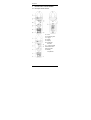
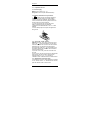
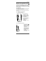
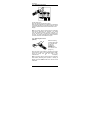
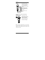
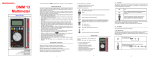
MX 350
Pince multimètre AC
AC Clamp-on meter
AC-Vielfachmesszange
Pinza multimetro AC
Pinza multímetrica CA
MX 355
Pince multimètre AC/DC
AC/DC Clamp-on meter
AC/DC- Vielfachmesszange
Pinza multimetro AC/DC
Pinza multímetrica CA/CC
Chapitre I
User's manual
Chapter II - page 17
2
MX 350 / MX 355
Chapter II
TABLE OF CONTENTS
1.
GENERAL INSTRUCTIONS ......................... 18
1.1.
Precautions and safety measures .............. 18
1.1.1.
Before using .......................................... 18
1.1.2.
When using the instrument.................... 19
1.1.3.
Symbols ................................................ 19
1.1.4.
Instructions............................................ 19
1.1.5.
Cleaning ................................................ 19
1.2.
Warranty .................................................... 20
1.3.
Maintenance .............................................. 20
1.4.
Unpacking - Repacking .............................. 20
2.
2.1.
2.2.
DESCRIPTION OF THE INSTRUMENT ....... 21
Description of front and rear....................... 21
Description of the display ........................... 22
3.
GENERAL DESCRIPTION ........................... 23
3.1.
Preparation for use..................................... 23
3.1.1.
Power supply......................................... 23
3.1.2.
Battery installation and replacement...... 23
3.2.
Zero mode / "Delta" function ...................... 23
3.3.
Memorization, automatic range .................. 23
3.4.
Auto cut-off................................................. 24
4.
4.1.
4.2.
4.3.
4.4.
4.5.
4.6.
4.7.
4.8.
FUNCTIONAL DESCRIPTION...................... 24
Measuring AC voltage ................................ 24
DC voltage measurement........................... 24
Measuring AC current ................................ 25
Measuring DC current ................................ 25
Measuring resistance ................................. 26
Continuity test with buzzer ......................... 26
Measurement of the voltage frequency ...... 27
Measurement of the current frequency....... 27
5.
TECHNICAL SPECIFICATIONS................... 28
5.1.
General ...................................................... 28
5.2.
Characteristics ........................................... 28
5.2.1.
DC voltage (Autorange)......................... 28
5.2.2.
AC voltage (Autorange) ......................... 28
5.2.3.
DC current (Autorange) ......................... 28
5.2.4.
AC current (Autorange) ......................... 28
5.2.5.
Resistance (Ω) ...................................... 29
5.2.6.
Hz frequency (Autorange) of a current .. 29
5.2.7.
Hz frequency (Autorange) of a voltage .. 29
5.2.8.
Safety ................................................. 29
5.2.9.
General information............................... 29
5.3.
Environmental conditions ........................... 30
5.3.1.
Temperature.......................................... 30
5.3.2.
E.M.C. ................................................. 30
5.4.
Accessories................................................ 30
MX 350 / MX 355
17
Chapter II
1.
GENERAL INSTRUCTIONS
1.1. Precautions and safety measures
1.1.1. Before using
You have just acquired a 4,000-count multimeter
clamp. We thank you for your confidence.
This multimeter clamp complies with the IEC 61010
norms concerning electronic measuring instruments.
For your own safety and to prevent damage to the
instrument, you must follow the instructions given in
this manual.
∗
This instrument can be used for measurements
on circuits in installation category II, in an environment
with pollution level 2, for voltages no greater than
300 V in relation to the earth.
∗
Definition of the installation categories
(see IEC 61010-1 publication):
CAT I: CAT I circuits are circuits protected by low
level transient over-voltage limiters
Example: protected electronic circuits
CAT II: CAT II circuits are household or similar
appliance power circuits, which may carry
medium-level transient over-voltage.
Example: household appliance and portable tool
power supplies
CAT III: CAT III circuits are high-power appliance
power circuits, which may carry high-level
transient over-voltage.
Example: industrial machinery or instrument
power supplies
CAT IV: CAT IV circuits are circuits which can
carry very substantial transient over-voltage.
Example: power feeders
For your own safety, only used leads that comply with
the IEC 61010 norm. Before using them, always
check that they are in perfect working order.
18
MX 350 / MX 355
Chapter II
1.1.2. When using the instrument
•
Never exceed the protection limit values indicated
in the specifications for each type of measurement.
•
When the multimeter clamp is linked to the
measurement circuits, do not touch any unused
terminals.
•
Before changing the function, disconnect the
measurement leads from the circuit measured.
•
Never measure resistances on a live circuit.
1.1.3. Symbols
Refer to the user's manual
Risk of electric shock
Dual insulation
1.1.4. Instructions
Before opening the instrument, disconnect it
from the measuring circuits and make sure that
you are not charged with static electricity, which
could irreparably damage the instrument's internal
elements.
-
A "qualified person" is someone who is familiar
with the installation, the construction, the
application and the dangers at hand. This
person is authorised to power up and power
down the installation and equipment, in
compliance with safety regulations.
1.1.5. Cleaning
Clean the instrument with a damp cloth and soap.
Never use abrasive products or solvents.
MX 350 / MX 355
19
Chapter II
1.2. Warranty
This equipment is guaranteed against any material or
manufacturing defects, in accordance with the general
conditions of sale.
During the warranty period (1 year), the instrument
can only be repaired by the manufacturer, who
reserves the right to repair the instrument or to
exchange all or part of it. If the equipment is returned
to the manufacturer, the outgoing transport costs are
borne by the customer.
The warranty is not applicable in the following cases:
1. improper use of the equipment or use of it in conjunction with incompatible equipment;
2. modifications to the equipment without the explicit
authorisation of the manufacturer's technical
depart-ment;
3. work carried out on the instrument by a person not
approved by the manufacturer;
4. adaptation for a specific application, not included
in the definition of the equipment or the user's
manual;
5. knocks, falls or flooding.
The contents of this manual must not be reproduced
in any form without our consent.
1.3. Maintenance
Return your instrument to your distributor for any work
to be done within or outside the guarantee.
1.4. Unpacking - Repacking
All the equipment was checked mechanically and
electronically before shipment. Every precaution was
taken to ensure that you receive the instrument
undamaged. It is a good idea to check quickly to
detect any damage that may have occurred during
transport. If there is any damage, immediately notify
the transporter of the customary reservations.
Caution!
If you ship this instrument on elsewhere, use
preferably the original packaging and indicate the reasons
for reshipment as clearly as possible in a note enclosed
with the equipment.
Our products are patented in FRANCE and ABROAD. Our
logos are registered trade marks.
We reserve the right to modify the characteristics and
prices should technological advances make it necessary.
20
MX 350 / MX 355
Chapter II
2.
DESCRIPTION OF THE INSTRUMENT
2.1. Description of front and rear
Jaws
Protective guard
Trigger
Switch
Display
COM input
terminals
+ input terminals
a HOLD function
b Zero button
Battery
compartment
MX 350 / MX 355
21
Chapter II
2.2. Description of the display
MX
350
MX
355
Batteries flat
Automatic range
Manual range
Hold
Continuity measurement
Voltage measurement
Current measurement
Resistance
measurement
Alternating current
Direct current
Negative value
Bargraph
Frequency measurement
DC zero/"delta" function
22
MX 350 / MX 355
Chapter II
3.
GENERAL DESCRIPTION
3.1. Preparation for use
3.1.1. Power supply
Battery: AAA or LR03 1.5 V x 2
Charge life: 100 hours (with alkaline batteries).
3.1.2. Battery installation and replacement
is displayed when the voltage supplied by
1.
the batteries is lower than the operating voltage.
2. Before changing the batteries, set the switch to
"OFF", disconnect the measuring leads and remove
the clamp from the circuit measured.
3. Loosen the screws and open the flap of the
battery compartment using a screwdriver.
4. Replace the flat batteries with 2 new 1.5 V LR03
batteries.
5. Put the battery flap back in place and tighten the
fixing screws.
3.2. Zero mode / "Delta" function
(MX 355) Press the "zero" button to select the "zero"
mode. The " " symbol is displayed. The last value
measured becomes the reference value which will be
subtracted from any subsequent measurements.
Press the button again: the " " symbol flashes and
the display indicates the reference value subtracted
from the measurements.
To quit the "zero" mode, press the zero button for 2
seconds.
In "zero" mode, the auto-range function is deactivated.
This function can also be used to perform RCD
measurements (in A, V or Ω) by recording a
"calibration value" subtracted from the measurements.
3.3. Memorization, automatic range
It is possible to freeze the value displayed by pressing
on the "HOLD" button. To deactivate this function,
press the "HOLD" button a second time.
MX 350 / MX 355
23
Chapter II
(MX 355) In A and V, it is possible to change the
range by keeping the RANGE button pressed. The
"manual range" symbol appears. The user can choose
the position of the decimal point. To quit the manual
range, you must keep the RANGE button pressed for
at least 2 seconds; the clamp then returns to AUTO
mode (Autorange).
3.4. Auto cut-off
The clamp shuts down automatically after 30 minutes
if no operations are performed.
To deactivate this function (MX 355 only), press the
"Zero" button and keep it pressed down. Then power
up the clamp.
4.
FUNCTIONAL DESCRIPTION
4.1. Measuring AC voltage
Set the switch to V~.
Connect the red test
lead to the "+" input
terminal and the black
test lead to the "COM"
input terminal.
Then place the touch
prods in contact with the
points where the AC
voltage is to be
measured.
Then read the result on
the display.
4.2. DC voltage measurement
Set the switch to V .
Connect the red test
lead to the "+" input
terminal and the black
test lead to the "COM"
input terminal.
Then place the touch
prods in contact with
the points where the
DC voltage is to be
measured.
Then read the result
on the display.
24
MX 350 / MX 355
Chapter II
4.3. Measuring AC current
Set the switch to A~.
Open the clamp by pressing the trigger.
Place the clamp around the conductor to be measured
and release the trigger; check that the clamp is closed
properly. Read the result of the measurement on the
display.
Note: For safety reasons, disconnect the measuring
leads before performing this operation. The clamp
must be positioned around a single conductor in a
circuit, with the risk of rendering the measurement
incorrect. The best measurement is obtained with the
conductor centred in the middle of the jaws.
4.4. Measuring DC current
(MX 355)
Before measuring
currents higher than
40 A, set the scale
to 400 A by
pressing the
RANGE button.
Then reset to zero
(see § 3.2)
Open the jaws of the clamp by pressing the trigger
and insert the cable to be measured between them.
Close the clamp and read the result of the
measurement
on
the display.
Note: For safety reasons, disconnect the measuring
leads before performing this operation. If reading is
difficult, press the HOLD button and read the result
afterwards.
MX 350 / MX 355
25
Chapter II
4.5. Measuring resistance
Set the switchto Ω.
Connect the red test lead to the
"+" input terminal and the black
test lead to the "COM" input
terminal.
Place the touch prods in
contact with the points to be
measured and read the result
on the display.
Note: When performing a
measurement on a circuit,
make sure that it is not live and
that the capacitors have been
discharged.
4.6. Continuity test with buzzer
.
Set the switch to
Connect the red test lead to the "+" terminal and the
black test lead to the "COM" terminal.
Place the touch prods in contact with the circuit to be
tested.
If the resistance is lower than 35 Ω, the buzzer sounds
continuously.
26
MX 350 / MX 355
Chapter II
4.7. Measurement of the voltage frequency
(MX 350)
Set the switch to "Hz".
Connect the red test lead to
the "+" terminal and the
black test lead to the "COM"
terminal.
Place the touch prods in
contact with the points
whose frequency is to be
measured.
Read the result on the
display.
4.8. Measurement of the current frequency
(MX 350)
Set the switch to "Hz".
Open the clamp by pressing
the trigger and insert the
cable to be measured.
Close the clamp and read
the result on the display.
Note: For frequency measurements, you can use either
the input terminals (voltage) or the jaws of the clamp
(current). If you use both sources, the result of the
measurement is false.
MX 350 / MX 355
27
Chapter II
5.
TECHNICAL SPECIFICATIONS
5.1. General
Only the values assigned tolerances or the limits
declared constitute guaranteed values. The values
without any tolerance are given as indications.
5.2. Characteristics
The accuracy is ± [% of the reading (R) + number of
representation units (digits or D)] in the reference
conditions (see appendix).
5.2.1. DC voltage (Autorange)
Range Measurement range Resolution
Accuracy
400 V
0.2 V to 399.9 V
0.1 V
1% R +2 D
600 V
400 V to 600 V
1V
1% R +2 D
Protection against overloads: 660 Vrms
5.2.2. AC voltage (Autorange)
Range
400 V
600 V
Meas. range
Frequency
0.5 V to 399.9V 50 .. 500 Hz
400 V to 600 V 50 .. 500 Hz
Resol.
0.1 V
1V
Accuracy
1.5%R +5 D
1.5%R +5 D
MX 350: Input impedance: 1 MΩ
MX 355: Input impedance: 10 MΩ
Protection against overloads: 660 Vrms
5.2.3. DC current (Autorange)
(MX 355)
Range Measurement range Resolution
Accuracy
40 A
0.10 A to 39.99 A
0.01 A
2.5% R +10 D
400 A
40.0 A to 400.0 A
0.1 A
2.5% R +10 D
Protection against overloads: 600 Arms
5.2.4. AC current (Autorange)
(MX 350)
Range
40 A
400 A
Meas. range
Frequency
0.05A to 39.99A 50 .. 60 Hz
60 ... 500 Hz
40.0A to 400.0A 50 .. 60 Hz
60 ... 500 Hz
Resol.
0.01 A
0.1 A
Accuracy
1.9%R + 5 D
2.5%R + 5 D
1.9%R + 5 D
2.5%R + 5 D
Protection against overloads: 600 Arms
(MX 355)
Range
40 A
Meas. range
Frequency
0.05A to 39.99A 50 .. 500 Hz
Resol.
0.01 A
Accuracy
2%R +10 D
400 A
40.0A to 400.0A 50 .. 500 Hz
0.1 A
2%R +10 D
Protection against overloads: 600 Arms
28
MX 350 / MX 355
Chapter II
5.2.5. Resistance (Ω)
Range
Meas. range
Resolution
Accuracy
1%R +2 D
400 Ω
0.2 Ω to 399.9 Ω
0.1 Ω
Max voltage: : 1.5 V DC during measurement.
Protection against overloads: 600 Vrms
Continuity detection threshold: R < 40 Ω
5.2.6. Hz frequency (Autorange) of a current
(MX 350)
Range
4000 Hz
10 kHz
Meas. range
Resol.
20 Hz to 3999 Hz
1 Hz
4.00 kHz to 10.00 kHz 10 Hz
Accuracy
Sensitivity
0.1%R + 1D 2 Arms
0.1%R + 1D 2 Arms
Protection against overloads: 600 Arms
5.2.7. Hz frequency (Autorange) of a voltage
(MX 350)
Range
4000Hz
40kHz
400kHz
1000kHz
Meas. range
2Hz to 3999Hz
4.00kHz to 39.99kHz
40.0kHz to 399.9kHz
400kHz to 999kHz
Resol.
1 Hz
10 Hz
100 Hz
1 kHz
Accuracy
0.1%R +1 D
0.1%R +1 D
0.1%R +1 D
0.1%R +1 D
Sensitivity
5 Vrms
5 Vrms
5 Vrms
10 Vrms
Input impedance: 1 MΩ
Protection against overloads: 600 Vrms
5.2.8. Safety
IEC 61010-1 Ed.95 and IEC 61010-2-032 Ed.93:
- Insulation: class II
- Pollution level: 2
- Altitude > 2000 m
- Installation category: CAT II 600V, CAT III 300V
5.2.9. General information
Digital display
3 ¾ digit LCD with max. reading of 3,999 counts
Analogue display
42-segment bargraph
Polarity
signal
When a negative signal is applied, the
appears.
Overload
symbol is displayed.
If the range is exceeded, the
Low battery indicator
is displayed when the voltage supplied by the
batteries is lower than the operating voltage.
MX 350 / MX 355
29
Chapter II
Sampling
2 measurements/second for the digital display
20 measurements/second for the bargraph
Protection level of the housing
IP30 according to EN 60529 Ed.92
Maximum jaw opening
MX 350:
∅ 26 mm
MX 355:
∅ 30 mm
Dimensions
(L x W x H): 193 x 50 x 28 mm
Weight
230 g (with batteries)
5.3. Environmental conditions
5.3.1. Temperature
Operation:
0°C to 40°C, < 70 % RH
Storage:
-10°C to 60°C, < 80 % RH
5.3.2. E.M.C.
Immunity:
Emission:
acc. to EN 61326 + A1 (1998)
acc. to EN 61326 + A1 (1998)
5.4. Accessories
Instrument delivered with:
1 user's manual
1 set of measuring leads (one black and one red)
2 x 1.5V AAA or LR3 batteries
1 carrying bag
APPENDIX: Reference conditions
Sine signal:
- Frequency from 48 to 65 Hz
- No DC component
Temperature 23°C ± 5°C
External magnetic field < 40 A/m
No AC magnetic field
Measured conductor centred (in A)
30
MX 350 / MX 355
METRIX
Pôle Test et Mesure - CHAUVIN ARNOUX
190, rue championnet
F - 75876 PARIX Cedex 18
Tel. 33 (0)1.44.85.44.85 - Fax 33 (0)1.46.27.73.89
Copyright ©
906129581 - Ed. 03 - 01/05