1
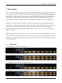
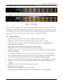
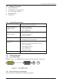
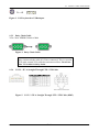
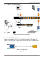
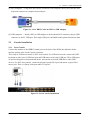
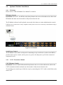
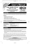
8 / 16 port combo KVM Switch 1+1 Console 8 / 16 port combo KVM Switch User Manual V2.0 2007.4.25 1+1 Console Combo KVM Switch Contents 1. Introduction............................................................................................................................... 4 1.1 Back Panel........................................................................................................................... 4 1.2 Main Features...................................................................................................................... 5 1.3 Package Contents ................................................................................................................ 6 1.4 System Requirements.......................................................................................................... 6 1.5 Cables Diagrams ................................................................................................................. 6 1.5.1 3-in-1 DB15 Cable ....................................................................................................... 6 1.5.2 PS/2 (keyboard) to USB adapter.................................................................................. 6 1.5.3 Daisy Chain Cable ....................................................................................................... 7 1.5.4 CAT5/5E/6 Straight Through UTP/STP Cable ............................................................ 7 16H 17H 18H 19H 20H 21H 2H 23H 24H 2. Hardware Installation............................................................................................................... 8 2.1 Rack Mount Installation...................................................................................................... 8 25H 26H 2.2 Computer/Server Installation .............................................................................................. 9 27H 2.2.1 3-in-1 HDDB15 Cable Installation .............................................................................. 9 2.3 Console Installation .......................................................................................................... 10 2.3.1 Local Console ............................................................................................................ 10 2.4 Optional Modules Installation............................................................................................11 2.4.1 IP Module................................................................................................................... 11 2.4.2 CAT5 Transmitter Module ......................................................................................... 11 2.5 Power ON.......................................................................................................................... 12 2.6 CAT5 KVM Receiver (R-Box) ......................................................................................... 12 2.7 CAT5 Receiver Installation............................................................................................... 12 2.8 When video signal is foggy or unclear ............................................................................. 13 2.9 Daisy Chain Connection ................................................................................................... 13 28H 29H 30H 31H 32H 3H 34H 35H 36H 37H 38H 3. Usage ........................................................................................................................................ 15 3.1 Hotkey Commands and OSD Operations ......................................................................... 15 39H 40H 3.2 3.3 3.4 3.5 4. 5. 6. Buttons .............................................................................................................................. 15 Front Panel -- Port LED Indications ................................................................................. 15 BANK 7-seg LED............................................................................................................. 16 Hot Plug ............................................................................................................................ 16 41H 42H 43H 4H Technical Specifications ......................................................................................................... 17 Troubleshooting....................................................................................................................... 18 Certifications ........................................................................................................................... 19 45H 46H 47H 2 / 19 1+1 Console Combo KVM Switch Figures Figure 1. Figure 2. Figure 3. Figure 4. Figure 5. Figure 6. Figure 7. Figure 8. Figure 9. Figure 10. Figure 11. Figure 12. Back Panel....................................................................................................................... 5 3-in-1 DB15 Cable .......................................................................................................... 6 PS/2 keyboard to USB adapter ....................................................................................... 7 Daisy Chain Cable .......................................................................................................... 7 CAT5/5E/6 Straight Through UTP/STP Cable (8P8C)................................................... 7 Rack Mount Installation.................................................................................................. 8 Footpads Installation ....................................................................................................... 8 Computer/Server Installation .......................................................................................... 9 3-in-1 DB15 cable........................................................................................................... 9 3-in-1 DB15 Cable and PS/2 to USB Adaptor.......................................................... 10 Local Console Installation ........................................................................................ 10 IP-Module ..................................................................................................................11 Figure 13. Figure 14. Figure 15. Figure 16. Connect to CAT5 Receiver (R-Box) ......................................................................... 12 Daisy Chain Connection ........................................................................................... 13 Daisy Chain through Computer Port......................................................................... 14 Front Panel ................................................................................................................ 15 0H 1H 2H 3H 4H 5H 6H 7H 8H 9H 10H 15H 14H 13H 12H 1H 48H 49H 50H 51H 52H 53H 54H 5H 56H 57H 58H 59H 60H 61H 62H 63H 3 / 19 1+1 Console Combo KVM Switch 1. Introduction The 1+1 Console 8/16 port KVM switch can control attaching servers and computers from local or remote console. This KVM switch is loaded with features such as one local console port, plus one optional CAT. 5-based remote console port or one optional IP-based remote console Port, On Screen Display (OSD) Menu, Password security, Hot key Control, Push Button and Auto Scan Control. It has complete keyboard and mouse emulation for simultaneous PCs boot-up process. With the CAT.5-based remote console port you can you remotely control servers and computers 1000 feet away. In other words, you can locate your monitor, keyboard and mouse up to 1000 feet away from the KVM switch. The built-in CAT.5 transmitter synthesizes VGA monitor and keyboard/mouse signals, and transmit the signals to the remote CAT.5 receiver over the popular LAN CAT.5 cable. With the IP-based remote console port you can control one or many computers locally at the server site or remotely via the Internet using a standard browser. You can securely gain BIOS level access to systems for maintenance, support or failure recovery over the Internet. Communication is secure via SSL encryption. 1.1 Back Panel 8 port combo PS/2 console KVM Switch 16 port combo PS/2 console KVM Switch 1+1 Console, 8 port combo PS/2 console KVM switch 1+1 Console, 16 port combo PS/2 console KVM switch with CAT5 extender module 4 / 19 1+1 Console Combo KVM Switch 1+1 Console, 16 port combo PS/2 console KVM switch 1+1 Console, 16 port combo USB console KVM switch with CAT5 extender module Figure 1. Back Panel The 1+1 console is designed as one control two views, both local console and remote console can access and view the same computer port, but only one console control at a time. These two consoles are operating on first come first served basis. If the controlling console does not have keyboard or mouse activity for 2 seconds, the other console may take over the control right. 1.2 Main Features Support combo interface for connecting to computer ports conveniently Support one local console and one optional remote console (CAT.5 or over IP) CAT.5 console up to 1000 feet away from KVM switch with superior auto-adjust RGB gain/delay control capability Support MS windows, Netware, Unix and Linux with PS/2 port Support iMAC, Power MAC and Sun Micro Systems with USB port No Software Required --- easy computer selection via On Screen Display (OSD) Menu, Push Buttons, and Hotkeys Provide various Hotkey (Scroll-Lock/ Cap-Lock/ Num-Lock/ L-Alt/ L-Ctrl/ L-Win/ R-Alt/ R-Ctrl/ R-Win) for switching computer port and other control functions, so Hotkey function can be used in various types of keyboards, and to avoid Hotkey duplicate problem. Provide ACL (Access Control List) security function. Store up to 8 independent user accounts Hot Plug --- add or remove connected computers without powering off the KVM switch or computers Support two user layers, and search computer/server name Plug-n-Play monitor support Keyboard status restored when switching computer Support Daisy Chain function with both Bus (8-layer) and Tree (2-layer) topologies 5 / 19 1+1 Console Combo KVM Switch 1.3 Package Contents 1x KVM Switch Unit 1x CD-ROM (User manual, QSG) 1x AC to DC Power Adapter 1x Rack Mount Kit 1x Footpads set 1.4 System Requirements Combo KVM Host side HDDB15 male to one HDDB15 male and two mini din 6-pin PS/2 connectors Local Console side (USB console) ■ One VGA Monitor ■ One USB Keyboard ■ One USB Mouse Local Console side (PS/2 console) ■ One VGA Monitor ■ One PS/2 Keyboard ■ One PS/2 Mouse IP Console module ■ One CAT.5 cable ■ Network access environment CAT.5 KVM extender module ■ ■ ■ ■ ■ ■ USB to PS/2 Adapter Optional for computer without PS/2 ports 1.5 One CAT.5 cable R-Box (CAT.5 KVM extender receiver) One VGA Monitor One USB Keyboard One USB Mouse Optional computer Cables Diagrams 1.5.1 3-in-1 DB15 Cable HDDB15 male to one HDDB15 male and two mini din 6-pin PS/2 connectors. Figure 2. 3-in-1 DB15 Cable 1.5.2 PS/2 (keyboard) to USB adapter PS/2 (keyboard) to USB (keyboard and mouse) adapter. 6 / 19 1+1 Console Combo KVM Switch Figure 3. PS/2 keyboard to USB adapter 1.5.3 Daisy Chain Cable VGA Cable: HDDB15 Male to Male Figure 4. Daisy Chain Cable Note: Daisy chain needs the cable all 15 lines connected. This is a special VGA cable, normal VGA cable has unconnected lines. Do not use other VGA cable for daisy chain. 1.5.4 CAT. 5 / 5E / 6 Straight Through UTP / STP Cable Figure 5. CAT. 5 / 5E / 6 Straight Through UTP / STP Cable (8P8C) 7 / 19 1+1 Console Combo KVM Switch 2. Hardware Installation Before installation, please make sure all of peripherals and computers have been turned off. 2.1 Rack Mount Installation Find a convenient place to put your KVM Switch. The 19” rack mount form factor makes it ideally mountable on a 19” rack. When mounting to a rack, attach the included brackets to the sides of the KVM Switch. Take note of the length of your cables so that your computers, KVM Switch, keyboard, mouse and monitor are distanced properly. Figure 6. Rack Mount Installation The KVM Switch can also be placed on a desk with attached footpads. To install footpads, please turn upside down; and refer to the following instructions properly for installing the footpads. Figure 7. Footpads Installation 8 / 19 1+1 Console Combo KVM Switch 2.2 Computer / Server Installation Figure 8. Computer/Server Installation 2.2.1 3-in-1 HDB15 Cable Installation On the back of the KVM Switch, each of the 8 /16 PC ports has a HDB15 type connector. Each cable that comes with the Switch has a 3-in-1 connector at one end and a single HDB15 male connector at the other end. Plug the single connector end of the cable into the KVM PC port, and then plug the other end of cable to a PC VGA port. Figure 9. 3-in-1 DB15 cable Figure 10. 9 / 19 1+1 Console Combo KVM Switch (a) PS/2 computer --- Plug in the PS/2 mouse connector to the computer mouse port, then the PS/2 keyboard connector to computer keyboard port. Figure 11. 3-in-1 DB15 Cable and PS/2 to USB Adaptor (b) USB computer --- Install a PS/2-to-USB adapter to the keyboard PS/2 connector, plug in USB connector to the PC USB port. This single USB port can handle both keyboard and mouse data. 2.3 Console Installation 2.3.1 Local Console Connect the monitor to the HDB15 female port on the back of the KVM unit labeled with the monitor symbol at the Local Console connector. There may be USB local console or PS/2 local console. For USB local console, connect the USB keyboard to either one of USB local port and USB mouse to the other USB port. These USB ports are special designed for keyboard and mouse, and can not work with USB hub or other USB devices. For PS/2 local console, connect keyboard to purple PS/2 port and mouse to green PS/2 mouse port. There is a Daisy chain port under VGA ports. Figure 12. Local Console Installation 10 / 19 1+1 Console Combo KVM Switch 2.4 Optional Modules Installation 2.4.1 IP Module Please refer to “IP KVM Module User Manual” for details. IP Remote Console Installation: Power off the KVM switch firstly. Remove the cover of the add-on slot, slide in the IP Module and make sure the module is fully inserted into the slot. The IP Module redirects local keyboard, mouse and video data to a remote administration console. It allows you to control one or many computers locally at the server site or remotely via the Internet using a standard browser. Figure 13. IP-Module Serial Power Control The IP Module comes with a serial port for connecting to any serial device, such as serial PDU to provide remote power control, such as power on, power off, and power cycle for the connected computers/servers. 2.4.2 CAT. 5 Transmitter Module CAT. 5 Remote Console Installation: Power off the KVM switch firstly. Remove the cover of the add-on slot, slide in the CAT.5 transmitter module and make sure the module is fully inserted into the slot. To extending your console up to 1000 feet away by connecting the CAT. 5 cable to the R-Box in the remote end. 11 / 19 1+1 Console Combo KVM Switch Figure 14. Connect to CAT. 5 Receiver (R-Box) 2.5 Power ON Check connections and plug in power supply Double check whether all cables/connectors are properly connected. You can check the color of keyboard and mouse connector to make sure the keyboard and mouse cables go to the correct port. Plug the power supply to the KVM switch and plug the AC power plug into the electrical receptacle. Now you will see the LED of Port 1 lights up, and hear a beep sound. Recommend Power ON sequence as follows: Monitor, KVM Switch, finally Computer. 2.6 CAT. 5 KVM Receiver (R-Box) The CAT.5 KVM receiver (R-Box) uses CAT.5 cable to extend your keyboard, mouse and monitor 1000 feet (300 meters) away from the KVM switch. It also has built-in 2-to-1 OSD KVM switch for selecting remote or local Computer. 2.7 2. 3. CAT. 5 Receiver Installation 5. 6. Make sure the CAT.5 cable is straight through type. Plug one end of CAT.5 cable into RJ-45 connector of the KVM switch CAT.5 console port, and plug the other end of CAT.5 cable into RJ-45 port of the R-Box. Connect keyboard, mouse and monitor to the R-Box console ports (USB Keyboard / Mouse port, and VGA port) Connect Local Computer to R-box with the accompanied 3-in-1 HDDB15 cable. Power on the R-Box by plugging in the power adaptor 7. Push the SELECT button to select remote or local Computer. 4. 12 / 19 1+1 Console Combo KVM Switch 2.8 When video signal is foggy or unclear The R-Box (CAT.5 Receiver) enables user to access to the computer, server, or KVM switch up to 1000 feet (300 meters) away with superior auto-adjust RGB gain/delay control capability CAT.5 cables has CAT.5, CAT.5e, CAT.6 and STP/UTP types; If your application need high VGA resolution and long distance please select high end cables. It is highly recommended to use optimal CAT5 cable length to get the best video quality and not waste unnecessary CAT.5 cable. 2.9 Daisy Chain Connection Use one end of daisy chain cable to connect to the Daisy Chain port of Master KVM switch and connect the other end of daisy chain cable to the Local Console port of the next Slave KVM switch. Please repeat the connection procedures for next Slave KVM switch. You can daisy chain up to eight banks in maximum. Master Slave 1 Slave 2 Figure 15. Daisy Chain Connection 13 / 19 1+1 Console Combo KVM Switch The console OSD menu will show only the port information of the master KVM switch. When the master unit starts up, it will query all daisy chained Slave units, and automatically set up the Bank ID for each Slave unit. So the 7-seg LED on the Master unit will display 1, Slave 1 will display 2, Slave 2 will display 3, and so on. If not so, please reset (press “BANK” and port button) the Master unit to update the Bank ID immediately. Hot Plug function is supported in daisy chain connection. The Master unit will auto-query the daisy chained Slaves every 30 seconds. You can also daisy chain through computer port. This daisy chain can work with other brand of KVM switch, but you need to change the Hotkey of slave KVM switch so that the master and slave KVM switch do not use the same Hotkey. Figure 16. Daisy Chain through Computer Port 14 / 19 1+1 Console Combo KVM Switch 3. Usage When you power on KVM switch, it will prompt a Login window waiting for user name and password. Please refer to “Hotkeys and OSD manual” for details. 3.1 Hotkey Commands and OSD Operations Please refer to “Hotkey and OSD User Manual” for details. 3.2 Buttons The push Buttons 1~8 : You can simply switch to a port by pressing the corresponding button. For 8 ports KVM Switch, please press button 1 ~ 8 directly to select the port you want. For 16 ports KVM Switch, please press “Shift” button and individual button 1~8 simultaneously to switch to the port from port 9 to port 16. For example: Pressing “shift” button and button 5 simultaneously to switch to port 13, and the port red LED will turn on. After power on the KVM switch, all of console ports (Local or Remote consoles) will be linked to Computer port 1. 3.3 Front Panel -- Port LED Indications 8 Ports 16 Ports Figure 17. Front Panel There are two LEDs for each port: ■ The Red LED on indicating a powered-on Computer is connecting to the port. Notice the PC99 Computer always power on the PS/2 ports even if the Computer is not power on, so the red LED will turn on. ■ The Blue LED on indicating the port has been selecting. The blue LED flashing if there is no Computer connected to the port. Press “BANK” button and the port button simultaneously will reset the KVM switch. 15 / 19 1+1 Console Combo KVM Switch 3.4 BANK 7-seg LED 7-Segment BANK LED Indication When you want to view the next bank KVM switch, please press “BANK” push button repeatedly to the destination bank. The bank LED will be changed from bank 1 to the maximum daisy chain level and then to bank 1 again. Bank 1 Bank 2 Bank 3 MAX. BANK 3.5 Hot Plug The KVM Switch supports “Hot Plug” function for any non-PS/2 connectors. You may Hot Plug the USB mouse or USB keyboard as you like. Note: ■ DO NOT hot plug PS/2 port. ■ Some O.S. (Operation Systems) like SCO Unix or Linux does not support “Hot Plug” function. If you apply “Hot Plug” to this kind of O.S., it will cause unpredictable behavior or shut down the Computer. Before attempting to use “Hot Plug”, please make sure your O.S. and mouse software driver support the “Hot Plug” function. 16 / 19 1+1 Console Combo KVM Switch 4. Technical Specifications Feature Specification KVM Type PS/2 Console KVM Console Ports One Local PS/2 console PC Port Connector PC Ports Max. Distance (KVM switch -- Host) Video Resolution (Local Console) VGA 8/16 Video Resolution (Remote Console) CAT5-Based Remote Console Module IP-Based Remote Module Daisy Chaining Computer port selection Hotkey PC Port LEDs 7-seg LED for Bank display USB Console KVM One Local USB console plus One Optional Remote Module 16 feet (5.0m) 1920 x 1440 1600 x 1200 for CAT5-Based 500 feet remote console. 1024 x 768 for CAT5-Based 1000 feet remote console. 1600 x 1200 for IP-Based remote console RJ-45 Connector, CAT.5 console up to 1000 feet away from KVM switch with superior, auto-adjust RGB gain/delay control capability RJ-45 8P8C for 10/100 M Ethernet, DB9 male for Modem, Null modem and serial power control, Mini USB 2.0 receptacle Support Daisy Chaining with both Bus (8-layer) and Tree (2-layer) topologies, DB15 Female Connector On Screen Display (OSD) Menu, Hot Key, Push Button Provide various Hotkey (Scroll-Lock/ Cap-Lock/ Num-Lock/ Alt/ Ctrl/ Win) 2x LEDs per PC port: Power (Red), Online (Blue) 1 set Multilingual OSD (On Screen Display) control Auto-Scan Intervals Keyboard Emulation Mouse Emulation Max. PC Connection Housing Provide ACL (Access Control List) security function, store up to 8 independent controllable Computers lists 8 languages (English, France, Germen, Spanish, Italian, Russian, Japanese, Simplified Chinese) 5 ~ 99 Sec. PS/2 or USB PS/2 or USB >1024 Metal Power DC Power adapter : 12V DC, 1A Operation Temperature Storage Temperature Humidity Mechanical Dimension (mm) 0 ~ 50℃ -20 ~ 60℃ 0~95%, Non-Condensing 19” Rack mount, 1U 444.5 * 160 * 44.3 Security 17 / 19 1+1 Console Combo KVM Switch 5. Troubleshooting 1. No LED display ■ Make sure the power adapter plugs in the KVM Switch. If the LED’s still won’t light, perform soft reset to KVM switch by press “BANK” button and last port button at the same time. ■ 2. 3. 4. 5. 6. Do the hard reset by unplug the power then plug in again. The computer boot up fine, but keyboard doesn’t work PS/2 keyboard or PS/2 mouse port is not designed for Hot Plug. USB mouse and keyboard can Hot Plug, but need to wait few seconds for Computer bus emulations. Don’t press any keys on the keyboard while the selected computer is booting up. Otherwise it might cause the keyboard error or keyboard is not detected at Host side. Make sure the keyboard works when directly plugged into the computer. Try a different keyboard, but use only 101, 102 or 104-key keyboard. The Mouse is not detected during PC boot up Make sure to plug in mouse first, then plug in keyboard. Make sure the USB or PS/2 mouse works when directly plugged into the computer. Avoiding moving the mouse or pressing the mouse buttons when switching ports. No video signal display on the remote monitor Please go to check all of VGA cables & connector and CAT.5 cable & connector are firmly connected. Video signal is foggy or unclear on the screen Please check if the VGA connector connected firmly. Check if the VGA resolution is too high for the length of CAT.5 cable being used. If the problem happened at VGA resolution, to shorten the CAT.5 cable length or reduce VGA resolution. It is highly recommended to use “optimal CAT.5 cable length” to get the best video quality and not waste unnecessary CAT.5 cable. If the CAT.5 Receiver is not connecting a local computer, please make sure the monitor is grounded properly. VGA resolution output mismatch with the monitor’s The KVM switch will provide DDC information to all the PC VGA board. If both the local console’s monitor and KVM switch are turned on before the PC boot up, or if the PC boot up faster then the KVM switch, the PC miss the DDC (Data Display Channel) information that causes the VGA resolution output mismatch with the monitor’s. In this case, please turn off the PC wait few minute then turn on again. 18 / 19 1+1 Console Combo KVM Switch 6. Certifications FCC This equipment has been tested and found to comply with Part 15 of the FCC Rules. Operation is subject to the following two conditions: (1) This device may not cause harmful interference (2) This device must accept any interference received. Include interference that may cause undesired operation. CE This equipment is in compliance with the requirements of the following regulations: EN 55 022: CLASS B. RoHS All contents of this package, including products, packing materials and documentation comply with RoHS. 19 / 19