1
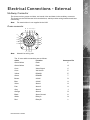
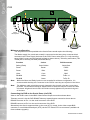
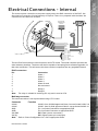
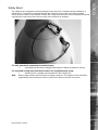
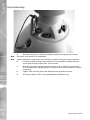
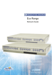
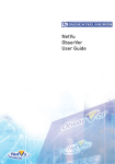
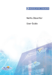
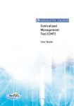
Oracle Dome Camera
Installation Manual
www.dedicatedmicros.com
Oracle
Contents
Introduction........................................................3
Components supplied - External........................ 5
Components supplied - Internal......................... 6
Electrical Connections - External....................... 7
Electrical Connections - Internal........................ 9
Mounting Configurations - External.................... 10
Mounting Configurations - Internal..................... 13
Control Configuration - All Models..................... 17
Upgrading Dome Software................................. 22
Dome Configuration...........................................24
Troubleshooting.................................................25
Notes..................................................................26
Whilst every attempt is made to ensure these manuals are accurate and current, Dedicated Micros reserve the right to
alter or modify the specification of the machine described herein without prejudice.
Dedicated Micros ©2008
Congratulations on choosing a Dedicated Micros Oracle dome camera.
This manual will provide all the necessary information to install the Dedicated Micros Oracle Dome
Camera.
Oracle
Introduction
RF Interference warning
This is a class A product. In a domestic environment this product may cause radio frequency
interference, in which case the user may be required to take adequate measures.
Product Safety
WARNING
•
Installation and servicing is only to be carried out by suitably qualified and
experienced personnel and should conform to all local codes.
•
Only power low voltage cameras from the provided power supply. Use only a Class
2 power supply with a maximum current of 1.5 amps and the wiring as specified in
the National Electrical Code ANSI/NFPA 70.
This camera range is designed for use in general purpose CCTV applications and has no other
purpose.
Only operate your camera between the temperatures of -10°C and +40°C. This low voltage camera
must be powered with either a 12V DC or a 24V AC power supply. Do not operate your camera
outside its specified power supply range.
FCC CLASS B REGULATORY NOTICE
This device complies with part 15 of the FCC Rules. Operation is subject to the following two
conditions: (1) This device may not cause harmful interference, and (2) this device must accept any
interference received, including interference that may cause undesired This equipment has been
tested and found to comply with the limits for a Class B digital device, pursuant to part 15 of the FCC
Rules. These limits are designed to provide reasonable protection against harmful interference in
a residential installation. This equipment generates uses and can radiate radio frequency energy
and, if not installed and used in accordance with the instructions, may cause harmful interference to
radio communications. However, there is no guarantee that interference will not occur in a particular
installation. If this equipment does cause harmful interference to radio or television reception, which
can be determined by turning the equipment off and on, the user is encouraged to try to correct the
interference by one or more of the following measures:
Reorient or relocate the receiving antenna.
Increase the separation between the equipment and receiver.
Connect the equipment into an outlet on a different circuit different to the receiver.
Consult the dealer or an experienced radio/TV technician for help.
Modifications not expressly approved by the manufacturer could void the user’s authority to
operate the equipment under FCC rules.
Dedicated Micros ©2008
Oracle
Camera Care
In order to avoid damaging your camera, note the following points:
CAUTION
•
•
Remove all packaging inserts and the protective film from the dome cover before
using the camera.
This installation should be made by a qualified service person and should conform
to all local codes.
CE NOTICE (EUROPEAN UNION).
Marking by the symbol CE indicates compliance of this DM product to the Electromagnetic
Compatibility Directive 89/336/EEC, and the Low Voltage Directive 73/23/EEC of the European
Union. Such marking is indicative that this system meets the following technical standards.
•
•
EN 61000-6-3 EMC Standard Residential, Commercial and Light Industry.
EN 61000-3-3 Limitations of voltage changes, fluctuations and flicker in public lowvoltage supply systems for equipment with rated current up to 16A.
•
EN 61000-3-2 Limits for harmonic current emissions for equipment with rated
current up to 16A.
•
EN 50130-4 Immunity requirements for components of fire, intruder and social
alarm systems.
•
EN 60950 Safety of IT and related equipment.
•
EN 55022 Class B. Radiated Emissions Standard, suitable for Commercial or
Residential use.
•
EN 60825-1 Safety standard for LED’s and Lasers.
Further details about these applicable standards can be obtained from Dedicated Micros Ltd. 1200
Daresbury Park, Daresbury, Cheshire, WA44HS.
A “Declaration of Conformity” with all relevant European Union Directives has been made, is on file
and is available from the Dedicated Micros address above.
This product is marked with the CE symbol and indicates compliance with all applicable directives.
Directive 89/336/EEC.
A “Declaration of Conformity” is held at Dedicated Micros Ltd., 1200 Daresbury Park, Daresbury,
Cheshire, WA44HS.
Dedicated Micros ©2008
Before installing the dome, please remove the components from the packaging and verify that all
items listed below have been supplied:
1 x Dedicated Micros Oracle Dome enclosure and camera (with incorporated safety bond)
1 x Oracle Dome Power Supply (except USA)
1 x Dedicated Micros Oracle Dome manual
Note for US Customers:
Oracle
Components supplied - External
The PSU must be a UL2044 approved Class 2 current limited 24VAC
Power Supply with a maximum current of 1.5 amps and the wiring as
specified in the National Electrical Code ANSI/NFPA 70.
Note: Mounting brackets may have been ordered and delivered separately.
Important: The Advanced Programming and Control features on the Oracle Dome are only
available when used with the latest Dedicated micros DVRs. These include DV-IP
Server, DV-IP HD, DV-IP RT and HighVu Excel. Standard functionality will still be
available with other control equipment.
Dedicated Micros ©2008
Oracle
Components supplied - Internal
Before installing the dome, please remove the components from the packaging and verify that all
items listed below have been supplied:
1 x Dedicated Micros Oracle Dome enclosure and camera (with incorporated safety bond)
1 x Dedicated Micros Oracle Dome manual
Note: The PSU must be a UL2044 approved Class 2 current limited 24VAC Power Supply with
a minimum current of 1.5 amps and the wiring as specified in the National Electrical Code
ANSI/NFPA 70. Dedicated Micros recommends the DM/94012 for indoor dome.
Note: Mounting brackets may have been ordered and delivered separately.
Important: The Advanced Programming and Control features on the Oracle Dome are only
available when used with the latest Dedicated micros DVRs. These include DV-IP
Server, DV-IP HD, DV-IP RT and HighVu Excel. Standard functionality will still be
available with other control equipment.
Dedicated Micros ©2008
Multiway Connector
Oracle
Electrical Connections - External
The dome receives power and data, and sends video and data via the multiway connector.
This feeds into the PCB housed in the terminal box, which provides wiring breakout and interconnectivity.
Note: The terminal box is not supplied in the USA.
Dome connector
B P A N M L
C
V
U
D
K
R
J
E
H
F
S G T
Note: Viewed from wiring side
The 15 core cable connections are as follows:
Cable
Function
Connector Pin
Green/Yellow
Earth
F
Green/Yellow
Earth
G
Coax Video Signal
C
Coax Vid Screen
P
Yellow
RS485A
E
Green
RS485B
T
Brown
24VAC
D
Blue
24VAC
U
Violet
Alarm 1
H
Pink
Alarm 2
S
Grey
Alarm 3
J
Orange
Alarm 4
R
Black
Alarm Ground
K
White
Relay A
N
Red
Relay B
L
Dedicated Micros ©2008
Oracle
PCB
J1
TEL
Tx/Rx -B
Tx/Rx +A
Relay B
Relay A
Alm Gnd
Alm 4
Alm Gnd
Alm 3
Alm Gnd
Alm 2
Alm Gnd
Alm 1
Relay B
Relay A
Alm Gnd
Alm 4
Alm 3
Alm 2
Alm 1
Pwr -
PWR +
Tx/Rx -B
Tx/Rx +A
Vid In -
Vid In +
Shield Gnd
Shield Gnd
TERM
24VAC-
24V AC +
- UTP
+ UTP
J2
DVR RS485
Telemetry
Future
development
Optional
Alarm/Relay
Inputs
DVR Video
Output
To Dome
Multiway
Connector
1
9
Minimum configuration
The simplest connection possible to the Oracle Dome would require the following;
The Mains supply (live, earth and neutral) is connected to the heavy duty connector block
mounted in the Power Supply Unit next to the PCB. Power select links (J1 & J2) should be
set to 24VAC (centre and arrowed pin bridged as shown above). Telemetry termination (TEL
TERM) link is normally not fitted (as shown above).
Function
Safety (Earth)
Colour
PCB Connector
Green/Yellow
Shield Gnd
Power
Brown
PWR+
Power
Blue
PWR-
Video
Coax
BNC
RS485A
Yellow
Tx/Rx +A
RS485B
Green
Tx/Rx -B
Note: Whilst the Alarm and Relay inputs are not essential for minimum configuration, it is
recommended that they are connected to the PCB in case they are required in the future.
Note: The Multiway cable should be securely clamped to the chassis using the screw clamp
provided. The insulation should be stripped back to allow the clamp to contact the cable
foil sheath. All glands into the PSU should be securely tightened to prevent the ingress
of moisture.
Connecting the DVR to the Oracle Dome (via PCB)
Video to the DVR is sent via the BNC Video/Control Output connection shown above.
Telemetry control is via the DVR RS485 Telemetry Inputs/Outputs connection shown above.
RS485A connects to Pin 1 on the serial connector of the DVR.
RS485B connects to Pin 9 on the serial connector of the DVR.
Alternatively the Oracle supports either up the coax (UTC) control via the video output BNC
connector or un-shielded twisted pair (UTP) via the UTP video/UTP net connectors (available via
future software upgrade).
Dedicated Micros ©2008
The dome requires connection to the power supply and to the BNC connection of the DVR. Use
the serial port connection if serial telemetry is required. There is no prepared cable included, the
connector for the camera is included.
Oracle
Electrical Connections - Internal
1
Reserved for
UTP/Ethernet
versions
9
TX+
TX-
BNC
Vid Sig
Vid GND
485B
485A
24VAC
24VAC
Pin 1 - Alarm 1
Pin 2 - Alarm 2
Pin 3 - Alarm 3
Pin 4 - Alarm 4
Pin 5 - Alarm Ground
Pin 6 - NC
Pin 7 - Relay A
Pin 8 - Relay B
+
-
24V Power
Supply
The two RJ45 connectors are used for alarms and UTP control. The serial connector provides the
serial telemetry interface. The dome will also be capable of accepting future software upgrades via
this serial connection. This will ensure the dome can be incorporated into any upgraded network.
RJ45 connectors
Pin
Connection
1
Alarm 1
2
Alarm 2
3
Alarm 3
4
Alarm 4
5
Alarm Ground
6
Not connected
7
Relay A
8
Relay B
Note: The relay is suitable for switching DC only and is rated at 0.7A.
Multiway connector
The serial connection is not required when using UTC Control.
Connector
Function
24VAC
24VAC+ from UL2044 approved Class 2 current limited 24VAC 1A
24VAC
24VAC- from UL2044 approved Class 2 current limited 24VAC 1A
485A
Pin 1 on Serial Connection to appropriate DVR
485B
Pin 9 on Serial Connector to appropriate DVR
Vid GND
BNC Earth (screen connection)
Vid Sig
BNC Signal (centre pin connection)
Note: Refer to ‘Dome Configuration’ for a list of appropriate DVRs.
Dedicated Micros ©2008
Oracle
Mounting Configurations - External
With appropriate brackets this dome enclosure can be mounted in any of the orientations
shown below.
Note: Mounting brackets may have been ordered and delivered separately.
1
2
3
4
5
1.
2.
3.
4.
5.
10
Wall/Pendant Mount (order code DM/90002) giving pendant or wall mount options.
Extended Wall Mount (order code DM/90009) for more flexibility in wall mounting.
Corner Bracket (order code DM/90007) for mounting to corners of buildings in
conjunction with DM/90002.
Snowdrop mount bracket (order code DM/90004) for mounting at the top of a pole
or column.
Pendant Mount (order code DM/90003 - 250mm; order code DM/90012 - 500mm;
order code DM/90013 - 1000mm; order code DM/90014 - 1500mm) for roof or
parapet mounting.
Dedicated Micros ©2008
The safety bond is designed to prevent damage to the dome if it is dropped during installation or
maintenance. It should be connected between the mounting point on the dome and a suitable
secure position, either on the bracket or within the ceiling void. Selection of this suitable point should
consider that it will receive the full force of the dome should it be dropped.
Oracle
Safety Bond
For wall, pendant & snowdrop mounted domes;
1.
Clip safety bond to the mounting bracket eyelet on flange of bracket to secure.
For standard ceiling mounted domes attach the supplied safety bond;
1.
Attach bond to a suitable secure position in the ceiling void.
Note: Always support dome with bond prior to mating connector. The weight of dome should be
supported by bond ensuring no stress is placed on centre connector at any time.
Dedicated Micros ©2008
11
Oracle
Dome Mounting
A.
Secure & hang dome to bracket by attaching safety bond spring clip to eyelet.
Note: Procedure is the same for all installations.
Note: Ceiling installation is made easier by removing an adjacent ceiling tile during installation.
B.
C.
D.
E.
12
Lift dome to bracket flange ensuring head of screws (previously fitted cap head
screw) pass through keyhole slots. Twist to locate.
Mate the previously prepared central connector, refer to ‘Electrical Connections’
for more information, supplying power & control to dome (ensure power is off when
connecting).
Tighten 4 top mounting fixings with Hexagonal key supplied to secure.
Secure any plastic covers or trim (wall/pendant installations only).
Dedicated Micros ©2008
With appropriate brackets this dome enclosure can be mounted in any of the orientations
shown below.
Oracle
Mounting Configurations - Internal
Note: Mounting brackets may have been ordered and delivered separately.
1
2
4
3
1.
2.
3.
4.
Wall/Pendant Mount (order code DM/90002) giving pendant or wall mount options.
Corner Bracket (order code DM/90007) for mounting to corners of buildings in
conjunction with DM/90002.
Tile mount (order code DM/CSD/TMR) for suspended ceilings.
Snowdrop mount bracket (order code DM/90004) for mounting at the top of a pole
or column.
Dedicated Micros ©2008
13
Oracle
Safety Bond
The safety bond is designed to prevent damage to the dome if it is dropped during installation or
maintenance. It should be connected between the mounting point on the dome and a suitable
secure position, either on the bracket or within the ceiling void. Selection of this suitable point should
consider that it will receive the full force of the dome should it be dropped.
For wall, pendant & snowdrop mounted domes;
1.
Clip safety bond to the mounting bracket eyelet on flange of bracket to secure.
For standard ceiling mounted domes attach the supplied safety bond;
1.
Attach bond to a suitable secure position in the ceiling void.
Note: Always support dome with bond prior to mating connector. The weight of dome should be
supported by bond ensuring no stress is placed on centre connector at any time.
14
Dedicated Micros ©2008
Pendant Mount
A.
B.
C.
D.
E.
Oracle
Dome Mounting
Secure and hang dome to bracket by attaching safety bond spring clip to eyelet.
Lift dome to bracket flange ensuring head of screws (previously fitted Cap head
Screw) pass through keyhole slots. Twist to locate.
Mate the previously prepared central connector, refer to ‘Electrical Connections’
for more information, supplying power & control to dome (ensure power is off when
connecting).
Tighten 4 top mounting fixings with Hexagonal key supplied to secure.
Secure any plastic covers or trim (wall/pendant installations only).
Dedicated Micros ©2008
15
Oracle
Tile Mount
Ø190mm
3 x Ø6mm
204mm PCD
A
C
D
B
E
F
A.
Remove the selected tile that will have the dome mounted in it. Use the mounting
ring (B) as a template to mark the drilling positions of the 3 x supporting holes on
a 204mm pitch circle diameter (6mmØ holes, if using the supplied cavity plugs (A))
and the 190mmØ hole for the dome. Fit the cavity plugs (A) to the holes.
Note: The installer is responsible for ensuring the fixings used to mount the dome are suitable for
the material and will adequately support the weight of the dome.
B.
C.
Attach the mounting ring to the dome using the provided 6 x M3x8 fixings (C).
Re-install the tile in the ceiling. Secure and hang dome to a suitable mounting point
in the ceiling void by attaching safety bond spring clip to eyelet through the large
centre hole in the tile.
Note: Ceiling installation is made easier by removing an adjacent ceiling tile during installation.
D.
E.
16
Fasten the dome to the mounting ring (B) using the provided 3 x No.8x1”(25.4mm)
self tapping screws (D) (or suitable fixings provided by the installer).
Snap fit the provided tile mount bezel (E). This replaces the standard bezel (F)
provided with the camera. Discard the standard bezel (F).
Dedicated Micros ©2008
Switch settings
Oracle
Control Configuration - All Models
Different controllers require different protocols and a red rotary switch is provided to select
the desired protocol. These are accessed by removing the outer hemisphere, refer to ‘Switch
Configuration’ for more information. There are three color coded switches, red, blue and yellow,
which are all located inside the dome camera housing. The blue and yellow switches have different
functions, depending on the protocol selected by the red switch.
Switch Configuration
To access the address switches and termination switch, remove the outer hemisphere by
unscrewing the six hemisphere securing screws. The location of the switches is shown. Access to
the switches is improved if the inner shroud is removed by taking out the four securing screws. This
operation should be carried out in an office type environment to avoid ingress of moist air.
RED SWITCH LOCATION
Function - Protocol Selection
Position
0
1
2
3
4
Protocol
Auto Sense (under development)
DM UTC (under development)
DM RS485
DM Current Loop (under development)
BBV UTC
Note: The selected protocol will be displayed on screen at power-up for a few seconds each time
the rotary switches are changed.
Dedicated Micros ©2008
17
Oracle
BLUE SWITCH LOCATION
Function - Dependant on Red Switch Configuration
UTC/Current Loop
Serial - Not Used
- Referenced by Camera Number on the DVR, refer to ‘Address
chart’ in section ‘RS485 Serial Connection’.
YELLOW SWITCH LOCATION
Function - Dependant on Red Switch Configuration
UTC/Current Loop
Serial - Not Used
- Referenced by Camera Number on the DVR, refer to ‘Address
chart’ in section ‘RS485 Serial Connection’.
TERMINATION SWITCH LOCATION (SW1)
Note: SW1 should be set towards the centre of PCB to turn RS485 termination ON or set away
from the centre of the PCB to turn RS485 termination OFF.
18
Dedicated Micros ©2008
Oracle
RS485/CURRENT LOOP TELEMETRY SWITCH LOCATION (SW2)
Note: SW2 should be set towards the centre of the PCB (RS485)
COAX OR DIFFERENTIAL VIDEO SWITCH LOCATION (SW3)
Note: SW3 should be set towards the centre of the PCB (coax).
RS485 Serial Connection
The coax cable and power wires are always connected.
The RS485 wires are only connected when an RS485 controller is being used.
The dome supports the DM RS485 PTZ protocols. The desired protocol and the node address for
the dome are selected by the rotary hex switches (red, blue and yellow) inside the dome. These
are accessed by removing the outer hemisphere and inner shroud, refer to Switch Configuration for
more information.
RS485 protocol allows multiple domes to be connected via the serial connection on the back of the
DVR. Each dome in the chain should have a unique individual address, to enable it to be called by
the DVR. The switch settings for the protocols and node addresses are shown in the table below.
Dedicated Micros ©2008
19
Yellow
Blue
Oracle
Address chart
0
1
2
3
4
5
6
7
8
9
A
B
C
D
E
F
0
1
2
3
4
5
6
7
8
9
A
B
C
D
E
F
0
16
32
48
64
80
96
112
128
144
160
176
192
208
224
240
1
17
33
49
65
81
97
113
129
145
161
177
193
209
225
241
2
18
34
50
66
82
98
114
130
146
162
178
194
210
226
242
3
19
35
51
67
83
99
115
131
147
163
179
195
211
227
243
4
20
36
52
68
84
100
116
132
148
164
180
196
212
228
244
5
21
37
53
69
85
101
117
133
149
165
181
197
213
229
245
6
22
38
54
70
86
102
118
134
150
166
182
198
214
230
246
7
23
39
55
71
87
103
119
135
151
167
183
199
215
231
247
8
24
40
56
72
88
104
120
136
152
168
184
200
216
232
248
9
25
41
57
73
89
105
121
137
153
169
185
201
217
233
249
10
26
42
58
74
90
106
122
138
154
170
186
202
218
234
250
11
27
43
59
75
91
107
123
139
155
171
187
203
219
235
251
12
28
44
60
76
92
108
124
140
156
172
188
204
220
236
252
13
29
45
61
77
93
109
125
141
157
173
189
205
221
237
253
14
30
46
62
78
94
110
126
142
158
174
190
206
222
238
254
15
31
47
63
79
95
111
127
143
159
175
191
207
223
239
255
To configure the Dome using DM RS485;
1.
Select DM RS485 by setting the red switch to position 2.
2.
Select a node address for the dome to be configured. Scan across the table to
identify the values for the blue and yellow switches; blue switch setting is shown
on the left, yellow switch setting on the right. For example, if the dome is to be
used with node address ID#5 the switches should be set to ‘05’. i.e. the blue switch
should be set to ‘0’ and the yellow switch set to ‘5’.
3.
Set the individual RS485 address for the dome on the blue and yellow switches
fitted inside the dome housing.
Note: The dome will display its protocol and address setting when first powered on as the screen
will show (in the example above) “Node Address 05”. It will also display briefly after each
time the setting is changed.
All Dedicated Micros Oracle domes are fitted with a termination switch (SW1), shown above. If a
single dome is connected on the RS485 line, or if a star configuration is used, the termination switch
should be switched to ‘ON’ (Switch towards the centre of the PCB).
If multiple domes are connected in a ‘daisy chain’ configuration, then only the last dome in the chain
should be switched to ‘IN’. All other domes in the chain should be switched to “OFF’ (Switch set
away from the centre of the PCB).
20
Dedicated Micros ©2008
Note: Only basic PTZ and preset functionality is available currently using UTC control. For full
programming and control including point&go and Absolute Positioning use RS485 control.
Commands to control the position of the dome can be transmitted up the same co-ax cable used to
transmit the video signal to the recorder station. Individual addresses do not need to be configured
within the dome because the instruction is sent directly to the dome.
Oracle
Up-The-Coax PTZ control
Note: The serial connection is not required when using Up-The-Coax control.
Up the Coax Switch Settings
Switch
Setting
Red
4
Yellow/Blue
Not required.
RED SWITCH LOCATION
BLUE SWITCH LOCATION
YELLOW SWITCH LOCATION
Dedicated Micros ©2008
21
Oracle
Upgrading Dome Software
The Oracle dome has an expanded feature and control set over other domes, which are only
available through the Dedicated Micros PTZ protocol.
These features are accessed through a set of web pages available on the latest Dedicated Micros
machines (DV-IP Server, DV-IP RT, DV-IP HD and HighVu Excel) and that will have access to
this dome. These pages will be available through the familiar unit interface and will allow easy
configuration of the domes features.
To upgrade dome software via RS485;
Note: The dome must be configured to RS485 telemetry to perform the software upgrade (Red
Switch to position 2).
Software is downloaded via the RS485 telemetry link on the dome, using a USB to RS485 converter
on the PC.
1.
2.
3.
4.
5.
7.
Download the software ‘domecfg’ and the application upgrade software from the
Dedicated Micros website.
Connect a USB to 485 converter to a USB port on your PC (see note below for
details of pin out for 9way Dtype connector).
Connect the RS485 serial lead from the Oracle dome to the output of the USB to
485 converter.
Launch the ‘Domecfg’ application.
Select ‘Setup’ (tab top left of window) in ComPorts window select drop-down
menu and select the PC COM port that has been assigned to the USB to RS485
converter.
Ensure the following settings are selected:
Baud rates:
9600
Parity:
None
Data bits:
8
Stop bits:
1
Flow control:
Xon char
17
Xoff char
19
8.
9.
Select ‘OK’
Select the Camera number (Cam box top left window) to ensure the upgrade
program addresses the packets to the relevant dome.
10.
Confirm that correct COM port has been selected by using the Up (U), Down (D),
Left (L) and Right (R) buttons to move the dome.
If settings are correct the dome should move when requested.
If not, check; The camera number equates to the dome address switch settings and
that the USB to RS485 converter is correctly configured.
11.
Select ‘File->Open’ and navigate to the downloaded application upgrade software
zip file. Left click the file and then press ‘Open’.
12.
Select ‘Upload’ to transfer the file to the dome. Upgrade takes approximately
twenty minutes, the progress can be monitored using the ‘Domecfg’ application or
by viewing the camera that is being upgraded via the unit it is connected to.
Important: The dome must not be powered down whilst a software download is in progress.
Powering down the dome could permanently corrupt the dome software.
13.
14.
15.
22
When the upgrade is complete, the ‘Domecfg’ application will display ‘Finished’.
Disconnect the RS485 telemetry cable from the USB to 485 converter and
reconnect to the serial port of the DVR.
Confirm correct operation using telemetry control of the DVR
Dedicated Micros ©2008
16.
Confirm the upgrade has been successful by checking the software version number
on the startup screen (This screen can also be displayed by special preset G4)
Dedicated Micros ©2008
Oracle
Note: Pin out for 9-way D-type connector to the DVR is normally Pin 1 for RS485+A and pin 9 for
RS485B. If the converter used is different then an intermediate cable may be needed to
transpose the wires (see converter’s documentation for pin out details).
23
Oracle
Dome Configuration
The Dome is configured via the attached DVR. The special software features are available via the
interface on DVR’s capable of accessing them (DV-IP Server, DV-IP RT, DV-IP HD and HighVu
Excel), refer to the documentation for your individual DVR for further details.
The Dome has advanced features that include Point and Go, Privacy masking, Presets, Sectors and
Patrols. along with Camera and Event settings. Some of these will be available to standard DVR’s.
List of DVR’s required to utilise advanced programming features
•
DV-IP Server, DV-IP HD, DV-IP RT and HighVu Excel running Gen3 pages.
Note: Standard functionality will still be available with all other control equipment.
24
Dedicated Micros ©2008
No picture
Oracle
Troubleshooting
Cause
1.
Check the Input voltage
2.
Check the continuity on the dome cable, refer to ‘Electrical Connections’ for more information.
Picture with intermittent control
Cause
This is most likely due to too much or too little video gain whilst using UTC telemetry.
Solution
Adjust using the Oracle dome settings page on the DVR.
Dome spins continuously (DM controllers)
Cause
No joystick dead band recognized as joystick was off centre during power-up.
Solution
Reboot the controller with the joystick self centred.
No telemetry control
Cause
Check the telemetry and address switch settings.
Note: Any changes to the switch settings are briefly displayed on the video output from the dome as
confirmation.
Dedicated Micros ©2008
25
Oracle
26
Notes
Dedicated Micros ©2008
Address chart............................................................................................................................................... 20
BLUE SWITCH LOCATION.......................................................................................................................... 18
Camera Care.................................................................................................................................................. 4
Oracle
Index
CE NOTICE (EUROPEAN UNION)................................................................................................................ 4
COAX OR DIFFERENTIAL VIDEO SWITCH LOCATION (SW3)................................................................. 19
Components supplied - External.................................................................................................................... 5
Components supplied - Internal..................................................................................................................... 6
Connecting the DVR to the Oracle Dome (via PCB)...................................................................................... 8
Control Configuration - All Models................................................................................................................ 17
Dome Configuration..................................................................................................................................... 24
Dome connector............................................................................................................................................. 7
Dome Mounting............................................................................................................................................ 12
Dome Mounting............................................................................................................................................ 15
Dome spins continuously (DM controllers)................................................................................................... 25
Electrical Connections - External................................................................................................................... 7
Electrical Connections - Internal..................................................................................................................... 9
FCC CLASS B REGULATORY NOTICE........................................................................................................ 3
For standard ceiling mounted domes attach the supplied safety bond;....................................................... 11
For standard ceiling mounted domes attach the supplied safety bond;....................................................... 14
For wall, pendant & snowdrop mounted domes;.......................................................................................... 11
For wall, pendant & snowdrop mounted domes;.......................................................................................... 14
Function - Dependant on Red Switch Configuration.................................................................................... 18
Function - Dependant on Red Switch Configuration.................................................................................... 18
Function - Protocol Selection....................................................................................................................... 17
List of DVR’s required to utilise advanced programming features................................................................ 24
Minimum configuration .................................................................................................................................. 8
Mounting Configurations - External.............................................................................................................. 10
Mounting Configurations - Internal............................................................................................................... 13
Multiway Connector........................................................................................................................................ 7
Multiway connector......................................................................................................................................... 9
No picture..................................................................................................................................................... 25
No telemetry control..................................................................................................................................... 25
Notes............................................................................................................................................................ 26
PCB................................................................................................................................................................ 8
Pendant Mount............................................................................................................................................. 15
Picture with intermittent control.................................................................................................................... 25
Product Safety................................................................................................................................................ 3
RED SWITCH LOCATION............................................................................................................................ 17
RED SWITCH LOCATION............................................................................................................................ 21
RF Interference warning................................................................................................................................. 3
RJ45 connectors............................................................................................................................................ 9
RS485/CURRENT LOOP TELEMETRY SWITCH LOCATION (SW2)......................................................... 19
RS485 Serial Connection............................................................................................................................. 19
Switch Configuration.................................................................................................................................... 17
Switch settings............................................................................................................................................. 17
TERMINATION SWITCH LOCATION (SW1)............................................................................................... 18
Tile Mount..................................................................................................................................................... 16
To configure the Dome using DM RS485;.................................................................................................... 20
To upgrade dome software via RS485;........................................................................................................ 22
Troubleshooting............................................................................................................................................ 25
Up-The-Coax PTZ control............................................................................................................................ 21
Upgrading Dome Software........................................................................................................................... 22
Up the Coax Switch Settings........................................................................................................................ 21
YELLOW SWITCH LOCATION.................................................................................................................... 18
YELLOW SWITCH LOCATION.................................................................................................................... 21
Dedicated Micros ©2008
27
Dedicated Micros Ltd.
1200 Daresbury Park, Daresbury,
Cheshire, WA4 4HS, UK
Dedicated Micros Europe
Neckarstrafle 15,
41836 Hückelhoven, Germany
Dedicated Micros USA.
14434 Albemarle Point Place, Suite 100,
Chantilly, Virginia 20151 USA
Dedicated Micros France
9-13 rue du Moulinet
75013 Paris, France
Dedicated Micros, Australia PTY.
5/3 Packard Avenue, Castle Hill,
NSW 2154, Australia
Dedicated Micros Slovenia
Delavska cesta 26,
4208 Sencure, Slovenia
Dedicated Micros, Asia PTY
16 New Industrial Road,
#03-03 Hudson Techno Centre,
Singapore 536204
Dedicated Micros Benelux
Joseph Chantraineplantsoen 1,
3070 Kortenberg, Belgium
Dedicated Micros Middle East
Building 12, Suite 302, P.O. Box 500291, Dubai Internet
City, Dubai, United Arab Emirates
Dedicated Micros (Malta) Ltd.
BLB017, Bulebel Industrial Estate,
Zejtun, ZTN08, Malta
Installed by
MI-I-OD/E1-1
PN. 740408