1
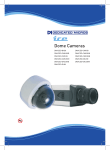
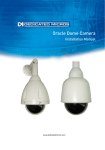
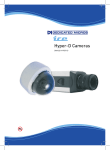
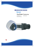
Vandal Resistant
Fixed Dome
Cameras
DM/ICEVC-BH39
DM/ICEVS-BH39
DM/ICEVS-OBH39
DM/ICEVC-CMH39
DM/ICEVS-CMH39
DM/ICEVS-OCMH39
DM/ICEVC-CMU39
DM/ICEVS-CMU39
DM/ICEVS-OCMU39
DM/ICEVC-DNU39
DM/ICEVS-DNU39
DM/ICEVS-ODNU39
Vandal Resistant Domes
Contents
Introduction........................................................3
Important Safeguards........................................4
Installation..........................................................5
Switch Settings..................................................8
Appendix............................................................10
Quickstart...........................................................11
Template............................................................15
Whilst every attempt is made to ensure these manuals are accurate and current, Dedicated Micros reserve the right to
alter or modify the specification of the machine described herein without prejudice.
Dedicated Micros ©2007
These instructions cover ICE series fixed dome cameras. Read all of these instructions. Use them to
install your camera and have them available for its lifetime. If you have any problems, contact your
agent.
Models
Mono high resolution
DM/ICEDVC-BH39
DM/ICEDVS-BH39
DM/ICEDVS-OBH39
570 TVL
0.07 lux at F1.2
Ceiling mount
Surface mount
Surface mount with outdoor heater
Vandal Resistant
Colour/Mono high resolution
DM/ICEDVC-CMH39
DM/ICEDVS-CMH39
DM/ICEDVS-OMH39
480 TVL
0.7 lux at F1.2
Ceiling mount
Surface mount
Surface mount with outdoor heater
Vandal Resistant
Colour/Mono ultra resolution
DM/ICEDVC-CMU39
DM/ICEDVS-CMU39
DM/ICEDVS-OCMU39
540 TVL
0.7 lux at F1.2
Ceiling mount
Surface mount
Surface mount with outdoor heater
Vandal Resistant
Day/Night ultra resolution
DM/ICEDVC-DNU39
DM/ICEDVS-DNU39
DM/ICEDVS-ODNU39
540 TVL
1.0 / 0.15 lux at F1.6 Vandal Resistant
Ceiling mount
Surface mount
Surface mount with outdoor heater
Vandal Resistant Domes
Introduction
Each model uses a 1/3” SuperHAD™ CCD.
Dedicated Micros ©2007
Vandal Resistant Domes
Important Safeguards
Product Safety
WARNING
•
Installation and servicing is only to be carried out by suitably qualified and
experienced personnel.
•
Do not remove covers as there is a risk of injury or death by electric shock.
•
Only power low voltage dome cameras from a class 2 isolated power supply.
This camera range is designed for use in general purpose CCTV applications and has no other
purpose.
Only operate your camera between the temperatures of -10°C and +50°C. Do not operate your
camera outside its specified power supply range.
Electromagnetic Compatability (EMC)
CAUTION
This product is intended solely for use in general CCTV applications.
The product must be installed and maintained in accordance with good installation practice to enable
the product to function as intended and to prevent problems. Refer to your agent for installation
guidance.
Declaration of Conformity
The manufacturer declares that the equipment supplied with this manual is compliant with the
essential protection requirements of the EMC directive 89/336 and the Low Voltage Directive LVD
73/23 EEC.
Conforming to the requirements of standards EN55022 for emissions, EN61000-4 parts 2, 3, 4, 5, 6
and 11 for immunity and EN60950 for Electrical Equipment safety.
Camera Care
In order to avoid damaging your camera, note the following points:
CAUTION
•
Remove all packaging inserts and the protective film from the dome cover before
using the camera.
•
Do not touch the image surface of the sensor. If the sensor is accidentally touched,
only clean it using isopropanol.
•
Do not expose the camera sensor to very bright light over a long period of time as
this may cause damage to the CCD sensor. The camera and lens set-up must be
correct to avoid possible damage due to long term exposure to bright light. A lens
with an automatic iris is recommended under these conditions.
Dedicated Micros ©2007
The ICE fixed dome camera is available in two versions: the ceiling mount version for installation
into a ceiling tile of up to 1.5” (38 mm) thickness; and the surface mount version for installation
directly onto a hard surface or mounting structure. When installing the outdoor vandal resistant
dome you must set the jumpers on the thermostat PCB to the correct supply voltage being used.
Parts Supplied
Ceiling Mount Models
Surface Mount Models
2 x Fixing screws
4 x Fixing screws
2 x Wall plugs
4 x Wall plugs
2 x Machine screws
4 x O-rings
2 x Sprung toggle clips Custom torx key
Custom torx key
This booklet
This booklet
Parts Not Supplied
•
Optional video service lead (part number DM/ICED-SERV)
Ceiling Mount Installation
Vandal Resistant Domes
Installation
Refer to the Quickstart section for more information.
1
2
3
4
5
6
7
8
Loosen the two torx screws on the front of the camera using the torx screw key
supplied.
Gently pull away the dome cover from the camera body and remove the plastic
shroud. The dome cover is attached to the camera body with a retaining cord. Do
not undo or cut this cord.
Using the template supplied at the rear of this booklet, mark and drill two 5/8”
(16 mm) holes at opposite sides of the large hole. Mark and cut a 4” (100 mm)
diameter hole. Check that the holes are large enough to enable the safety lugs on
the camera body to pass through.
Mark and drill the two screw holes for fixing the camera body. Two pairs of screw
holes are provided on the camera body for ease of fixing. Use only one pair of
screw holes. A 5 mm drill bit is suitable for use with the supplied wall plugs.
Connect the video cable to the BNC connector at the end of the flying lead or
directly to the BNC connector on the camera body. Use only one of the BNC
connectors to connect the video cable. Connect the power cable to the power
terminals. The camera operates from a 12V DC or 24V AC power supply.
Connections and polarity are indicated next to the terminals. The power supply
must be a UL Listed, Class 2 isolated type.
Optionally attach a safety chain (not supplied) to one of the lugs and secure the
other end of the safety chain to a fixed object.
Insert the camera body into the hole and fix it to the ceiling tile using either the
wood screws and wall plugs supplied or the two machine screws and sprung toggle
clips. Do not over-tighten the screws.
Optionally attach a local monitor to the test point using an DM/ICED-SERV service
connector (available separately) and adjust the camera as described earlier.
Visually align the screws on the dome front cover with the screw holes on the
camera body to assist in replacing the dome cover.
Replace the dome front cover and tighten the torx screws, taking care not to
trap the retaining cord in the edge of the front cover. Do not over-tighten the torx
screws.
Dedicated Micros ©2007
Vandal Resistant Domes
Note:
This dome uses non standard Torx screws for increased security, which can only be
unfastened using the provided tool.
Surface Mount Installation
Refer to the Quickstart section for more information.
Video and power cables enter the camera body inside a plastic or metal conduit either from
the side or rear of the camera.
1
Loosen the four torx screws on the front of the camera using the torx screw key
supplied.
2
Gently pull away the dome cover from the camera body and remove the plastic
shroud. The dome cover is attached to the camera body with a retaining cord. Do
not undo or cut this cord.
3
Unscrew one of the two large screws, either at the side or rear of the camera body,
depending on where the video and power cables are to enter the camera body.
Note that the screw is wrapped in PTFE tape. This is necessary to ensure that
moisture does not enter the camera body after the camera has been installed.
4
Using the template supplied at the rear of this booklet, mark and drill the four screw
holes required for fixing the camera body. An 8 mm drill bit is suitable for use with
the supplied wall plugs.
Note: If the video and power cables enter from the side of the camera, you may wish to fit
a conduit in position temporarily at the side of the camera to align the camera before
marking the screw holes.
If the video and power cables enter from the rear of the camera, mark and drill a
hole for the conduit and leads. The size of hole required depends on the size of the
conduit. The template shows the position of the large screw hole at the rear of the
camera.
5
Attach a metal or plastic conduit with a suitable M20 screw thread to the side
or rear entry point using PTFE tape to ensure a watertight seal. Ensure that the
conduit does not foul the plastic camera mount inside the camera body.
6
Screw the camera body to the fixing surface using the screws, wall plugs and
o-rings supplied. O-rings must be used to ensure that moisture does not enter the
camera body after the camera has been installed. Do not over-tighten the screws.
7
Connect the video cable to the BNC connector at the end of the flying lead.
Connect the power cable to the power terminals. The camera operates from a 12V
DC or 24V AC power supply. Connections and polarity are indicated next to the
terminals. The power supply must be a UL Listed, Class 2 isolated type.
8
Optionally attach a local monitor to the test point using an DM/ICED-SERV service
connector (available separately) and adjust the camera as described earlier.
9
Visually align the screws on the dome front cover with the screw holes on the
camera body to assist in replacing the dome cover.
10
Replace the dome front cover and tighten the torx screws, taking care not to
trap the retaining cord in the edge of the front cover. Do not over-tighten the torx
screws.
Note:
This dome uses non standard Torx screws for increased security, which can only be
unfastened using the provided tool.
Dedicated Micros ©2007
Camera Position
The camera assembly is adjustable in all three axes. Adjust the camera until it is pointing in the
desired direction.
FOV & Focus
Use the levers on the varifocal lens to adjust the camera’s field of view, and focus.
Dedicated Micros ©2007
Vandal Resistant Domes
Camera Adjustment
Vandal Resistant Domes
Switch Settings
The DIP switches are located on the camera’s circuit board.
Switch
Function
1
Backlight Compensation
2
Automatic Gain Control
3
Electronic Iris
4
Line Lock
Switch
Function
1
Day/Night
2
Colour Burst
OFF ON
INT
LL
OFF ON
HI
LO
Default setting
White indicates switch position
Backlight Compensation
The Backlight Compensation (BLC) feature compensates for back-lit scenes by enhancing objects in
the centre of the scene which would previously have been in silhouette. Select ON or OFF using the
BLC switch. Default is OFF.
AGC (Automatic Gain Control)
The Automatic Gain Control (AGC) feature can improve picture quality when levels of illumination
are low. Select ON or OFF using the AGC switch. For most applications the AGC feature should be
ON and is therefore the default setting.
Electronic Iris
The Electronic Iris (EI) feature compensates for excessive light levels by automatically adjusting the
shutter speed. For auto-iris lenses, the EI should be set to OFF. For manual lenses, EI should be
ON.
Line Lock
Choose INT (internal) or LL (adjustable). The LL setting allows ±180° phase adjustment via the two
LL Phase Advance/Retard buttons. Default is LL.
Pressing both buttons simultaneously will reset LL to the factory default setting.
The LL setting can be adjusted using the LL potentiometer available on some versions of this
product.
Dedicated Micros ©2007
(DN Versions only)
This switch sets the light level at which the camera automatically switches between day and night
operation. Hi sets the camera to switch between day and night mode at higher light level. Lo sets the
switching point at a lower light level. The default setting is Lo.
When in Night mode, the IR cut filter is removed allowing infra red illumination to be used.
Colour Burst
(DN versions only)
The Colour Burst (CB) switch allows the colour burst component of the signal to be turned on or off.
When a day/night camera switches to night (mono) mode, the colour burst can be switched OFF
for a true monochrome signal. Note that some multiplexers/recorders detect video-loss if the colour
burst signal disappears. If problems are encountered with the multiplexer/recorder when the camera
switches to mono, try setting CB to ON. Default is CB OFF.
Lens Level
Adjust the lens iris level according to the lighting conditions.
1
2
3
Turn the Automatic Gain Control switch OFF
Adjust the Lens Level potentiometer so that a 1 V peak-to-peak signal is achieved.
Use care so as not to damage the potentiometer.
Turn the Automatic Gain Control switch ON
Vandal Resistant Domes
Day/Night
Local Video Out
Provision is made for the connection of a local video monitor to assist in setting up the camera. Use
the optional service connector DM/ICED-SERV (not supplied).
Final Assy
When all the connections and adjustments have been made, re-attach the camera liner and dome
cover.
Dedicated Micros ©2007
Vandal Resistant Domes
Appendix
Dimensions
VC version
A
112 mm
4.41"
160 mm
6.30"
160 mm
6.30"
96 mm
3.78"
66 mm
2.60"
B
104 mm
4.09"
95 mm
3.74"
148 mm
5.83"
148 mm
5.83"
55 mm
2.17"
VS version
10
Dedicated Micros ©2007
VS VERSIONS
Dedicated Micros ©2007
Vandal Resistant Domes
Quickstart
11
Vandal Resistant Domes
12
Dedicated Micros ©2007
VC VERSIONS
Dedicated Micros ©2007
Vandal Resistant Domes
Quickstart
13
Vandal Resistant Domes
14
Dedicated Micros ©2007
Vandal Resistant Domes
Template
Pattern for VC Ceiling Dome
)
6”
9 /1
(4
m
10
0m
m
4m
11
(4
”)
5mm(3/16”)
16mm(5/8”)
NOT TO SCALE
Pattern for VS Ceiling Dome
15mm
57mm
ø8mm
mm
70
NOT TO SCALE
0m
10
m
Dedicated Micros ©2007
15
Dedicated Micros Ltd.
1200 Daresbury Park, Daresbury,
Cheshire, WA4 4HS, UK
Dedicated Micros Europe
Neckarstrafle 15,
41836 Hückelhoven, Germany
Dedicated Micros USA.
23456 Hawthorne Blvd.
Suite 100, Torrance,
CA 90505, USA
Dedicated Micros France
9-13 rue du Moulinet
75013 Paris, France
Dedicated Micros, Australia PTY.
5/3 Packard Avenue, Castle Hill,
NSW 2154, Australia
Dedicated Micros Slovenia
Delavska cesta 26,
4208 Sencure, Slovenia
Dedicated Micros, Asia PTY
16 New Industrial Road,
#03-03 Hudson Techno Centre,
Singapore 536204
Dedicated Micros Benelux
Joseph Chantraineplantsoen 1,
3070 Kortenberg, Belgium
Dedicated Micros Middle East
Building 12, Suite 302, P.O. Box 500291, Dubai Internet
City, Dubai, United Arab Emirates
Dedicated Micros USA.
14434 Albemarle Point Place, Suite 100,
Chantilly, Virginia 20151 USA
Dedicated Micros (Malta) Ltd.
BLB017, Bulebel Industrial Estate,
Zejtun, ZTN08, Malta
MI-I-ICEVR/E1-0