1
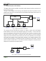
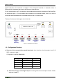
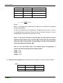
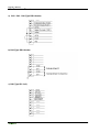
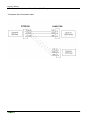
RUA CENTRAL DA VERGADA, 1280
4535-166 MOZELOS VFR - PORTUGAL
TEL.: + 351 227 471 120 FAX.: +351 227 471 129
E-mail: [email protected]
WEB: www.egitron.pt
Manual of InterLab – version 2.1
InterLab - Manual
2
InterLab - Manual
Exemption of Responsibility
This manual was produced and revised in order to describe in the most accurate way as possible the
functioning and the characteristics of the InterLab. However this manual or equipment can be altered
without previous notice. EGITRON is not responsible for damages directly or indirectly caused by errors,
omissions or discrepancies between the InterLab the instructions or descriptions contained in this
manual.
This document, or any part of it, cannot be reproduced or transmitted by any format or for any propose,
without previous authorization from EGITRON.
Conformity Declaration
This product exhibits
marking, according to European Union applicable directives.
Warranty and Technical Assistance
EGITRON guarantees the correct functioning of EGITRON products, matter of this warranty, in general
for one year, or for a different period if written stated by EGITRON. The Warranty covers the
workmanship and necessary materials but not the equipment transport or travel expenses to client’s
facilities, which will be charged according to the current price list. There is an exception for the first
displacement if done within the warranty first month, which will be free.
If the equipment has any malfunction during the warranty period, EGITRON guarantees, and according
to his own procedures, to repair or replace it without any cost, except in the following situations. Any
replaced product and/or part will be EGITRON property.
The warranty will not have effect in malfunctions caused by equipment non imputable causes like:
Malfunction caused by usage mistakes, negligence or handling against the manual instructions,
by parts and components modification or incorporation performed by non authorize technical
services;
Defects caused by short circuit or mechanical injury;
Indemnity for personal or material damages caused directly or indirectly;
To use the warranty services is necessary to contact EGITRON technical services. EGITRON has the
right to ask the client for the equipment purchase invoice.
3
InterLab - Manual
This equipment is design only to be used for which is manufactured. EGITRON is not responsible for its
improper use.
In case of malfunctioning or request for technical support
Before asking for EGITRON support read the Problems Resolution chapter, call your company technical
support (if available) and/or use all existing auto-help tools.
If the problem remains unsolved contact EGITRON, having with you the following information:
Equipment name
Serial number
Purchase date
Problem description
Error message that may appear.
4
InterLab - Manual
Introduction ............................................................................................ 6
Chapter 1
1.1 – General Description of the Hardware ...................... 7
1.2 – Configurations / Functions ....................................... 8
1.3 – Connectors Pinout ................................................. 13
1.4 – Connection between InterLab and Computer ....... 14
Chapter 2
Format of the Communication of the InterLab in Automatic Mode
2.1 – General Description .............................................. 15
2.2 – Commands List ...................................................... 16
2.3 – Values sent from InterLab from PC ....................... 18
Appendix
Technical Characteristics................................................. 21
Notes ...................................................................................................... 22
5
InterLab - Manual
Introduction
The so called InterLab system is based on a microcontroller that allows the control and automatic
acquisition of information proceeding from different measurement devices and mainly it aims the
automatization of quality control technical sheets, bulletins, reports or certificates elaboration.
The InterLab, as an interconnection unit of different characteristics equipment, shows the following
functions:
1. Interconnection to equipment with an analogical outlet. It offers the possibility of interconnecting
simultaneously two devices with different measurement range characteristics, one of them can
be an Aqua-Boy. The considered resolution is of 10 bits;
2. Interconnection to measure devices for dimensional control (digital caliper or other devices with
Mitutoyo compatible interface);
3. Interconnection to devices with communication port series RS232C (for instance, scales, loading
cells, etc.); there is also the possibility of simultaneous interconnection of two devices;
4. Connection to a personal computer, from a serial communication port RS232C or USB using a
RS232/USB converser;
5. Setting of the measures on a liquid crystal display (LCD);
6. Functioning in manual / automatic modus or local / remote modus.
A brief presentation of the hardware, configuration and description of the existing signals in each
connector of the Interlab will follow.
At last the communication format that should exist between the computer and the InterLab will be
presented.
6
InterLab - Manual
Chapter 1
1.1 – General Description of the Hardware
The diagram bellow shows the possible communication tracks between the devices connected to the
InterLab and the computer.
The figure 1 shows a diagram of the functioning, in the automatic mode, where it is possible to see the
possible devices that may be connected and the communications tracks between these devices, the
InterLab and a computer.
CPU
CN6
Analogical Inputs
(Aqua-Boy)
CN2
CN5
CN4
CN3
Digital
Calipper
Scale
Torsiometer /
PerfiLab
Computer
Figure 1 – Diagram of Communications in Automatic Mode
The connectors CN5 and CN6 allow the connection of a caliper or another device with Digimatic
Interface (Mitutoyo) and two devices with analogical outputs (as an Aqua-Boy). A torsion meter and a
scale can be connected to CN3 and CN4, which are RS-232C type connectors, as well as any other
device with RS-232C series interface. In automatic mode, and as stated on the above mentioned
diagram they work as bi-directional communication ports and have the particularity of any information
sent through those periphery devices being directly conducted to the computer through the CN2
connector and any information or command sent by this one passes first by the InterLab. There are
special commands, as stated further on, which allow the InterLab to distinguish the characters that are
supposed to be sent directly to the periphery devices.
CN2
CN4
CN3
Scale
Torsiometer /
PerfiLab
Computer
Figure 2 – Diagram of communications with CN3 and CN4 in Manual Mode
7
InterLab - Manual
For this last situation, the characters to be sent to the devices will have to be embedded between
special characters, as mentioned in chapter 2. This will permit InterLab, in automatic mode, to
differentiate the characters that must be directly sent to these devices.
For the manual mode, the PC can directly communicate with the devices connected via CN3 and CN4,
as shows the figure 2. For this situation, and contrarily to the automatic mode, there is no need to
embed with special characters the commands sent from the PC to the devices.
The figure 3 shows an inside-upper view of InterLab.
LD2
LD3
LD1
DISPLAY LCD 2 X 20
ON / OFF
Table 1
LD9 LD8
Analogical
Inputs
(Aqua-Boy)
LD7
LD6
LD5
LD4
Digital
Calipper
Scale
Torsiometer /
PerfiLab
Computer
Figure 3 – Inside-upper view of InterLab
1. 2 – Configurations/ Functions
a) Selection of the communication speed (baud-rate): done throw the micro-interrupters 1 and 2 of
SW3, as shown in table 1
Configuration by default (9600,N,8,2)
SW3-1
SW3-2
Baud-Rate
OFF
OFF
2.400
ON
OFF
4.800
OFF
ON
9.600
ON
ON
19.200
b) Selection of the type of analogical input: done through the micro-interrupters 3 and 4 of SW3,
as shown in table 2:
8
InterLab - Manual
Table 2
SW3-3
SW3-4
Input Type
OFF
OFF
Aqua-Boy KOM IV
OFF
ON
Aqua-Boy KOM II
ON
OFF
Yout=kXin(*)
ON
ON
Aqua-Boy KOM I
( Xin in mV )
(*) Yout
1024
xGxXin
5000
Where:
Yout: is the digital value indicated by the display of the InterLab and calculated
through this expression.
G: Gain of the amplifier at the InterLab input. The gain may vary from 6,8 to 16,8 for
the analogical input connected to the pins 8 and 9 of CN6 and closed to 10 for the
analogical input connected to the pins 6 and 7 of CN6
Note 1: In case of the connection of an Aqua-Boy, this only must be connected
between the pins 8 and 9 of the connector CN6. For this case, the value shown
will be the value of the moisture corresponding to the type of the hygrometer
selected through the interrupters SW3.
Note 2: If the end-of-scale value of the different types of hygrometers is
reached, the InterLab will provide the following values
KOM I – 11 %
KOM II – 21 %
KOM IV – 31 %
c) Selection of the language: done through the micro-interrupter 5 of SW3, as shown in table 3.
Table 3
SW3-5
Language
ON
English
OFF
Portuguese
9
InterLab - Manual
When the InterLab is switched on you can verify on the LCD display, the selected baud-rate.
Whenever you want to change it, you should switch off the InterLab, so that the new
configuration can be assumed. As stated further on, the Aqua-Boy type also can be selected by
software while operating through an existing command and without needing of altering the
selectors SW3-3 and SW3-4.
SW1 - Push button that allows to select the operation type of the InterLab (MANUAL or AUTOMATIC).
Note: The InterLab should be in AUTOMATIC mode for a normal operation controlled by the
PC. Whenever the InterLab is switched on, it starts in automatic mode and the Led LD1 switches
on the light; the led LD9 will blink. When you push the pressure button SW1 the Interlab
switches on operating mode. The operation mode is also indicated on the LCD screen. The
manual mode (Led LD1 switched off) will allow a local control and it is used mainly to make tests
to the InterLab.
SW2 - Push button that allows on MANUAL mode to select the desired measurement device.
Whenever this button is pushed the selection of another device is made and the respective Led
starts twinkling.
SW4 - Power switch. LD3 lighted indicates that InterLab is switched on.
SW5 - Push button that allows the delivery of data coming from analogical input (hygrometers), or
caliper, connectors CN6 and CN5 respectively, to the PC. Whenever this button is pushed the
InterLab reads the value of the entry of the hygrometers or caliper, if any one is selected and
sends that value to the computer. Whenever the data are sent to the computer the Led LD4
twinkles.
LD1 – Led for automatic mode indication.
LD3 – Led indicating that the InterLab is switched on (“Power Led”).
LD4 – Led that switches on when the value is sent to the PC throw the connector CN2.
LD5 to LD9 – Leds for the indication of the selected input. The indication of the selected input is done
by the respective Led that is blinking in the LCD display. Between parentheses there is the
indication given in the LCD display.
LD5 – Input of the Torsiometer / PerfiLab (Torsiometer).
10
InterLab - Manual
LD6 – Input of the Scale (Digital Scale).
LD7 – Input of the Caliper (Caliper)
LD8 – Analogical Input B (Hygr. B)
LD9 – Analogical Input A (Hygr. A)
PT1 - Potentiometer to adjust the A/D converter reference tension (5 volt). The user shouldn’t change
this adjust, since this is done by the supplier.
PT2 - Potentiometer to adjust the gain of the signal proceeding from the analogical input A (Aqua-Boy
Moisture meter) and that permits to get a gain between 6,8 and 16,8. To conduct this calibration,
the Aqua-Boy must be connected to the InterLab by the pins 6 and 9 of the connector CN6 since
just this one permits the adjust of the tension gain and then the potentiometer must me regulated
so that the value that appears on the display be equal to the one indicated by the Aqua-Boy
pointer as indicates the following procedure.
Procedure for adjustment of the hygrometers Aqua-Boy:
1. Open the upper cover of the InterLab, loosening the four lateral screws.
2. Search the components SW3 and PT2. In order to get help, see the picture of Figure 3.
3. Switch on the InterLab. Connect the Aqua-Boy to the InterLab throw the pins 8 and 9 of CN6.
4. Check if the type of hygrometer selected in the InterLab (see the LCD display) corresponds to
the one that is connected (Ex. KOM IV). If it does not, change in SW3 the interrupters 3 and/or
4 as the configuration indicated in Table 2. If the configuration of the SW3 has to be changed,
you will have to switch of the alimentation of the InterLab and switch it back on for the
configuration to be considered.
5. After being sure that the model of the hygrometer is correct, adjust the PT2 with a screwdriver
6. Proceed with the read a value in the hygrometer and compare it with the value in the LCD
display of the InterLab. If the value differs, adjust PT2 pressing simultaneously the reading
button of the hygrometer and rotating with the screwdriver the head of the screw of PT2, until
getting a value as closed as possible as the value shown in the galvanometer of the
hygrometer.
7. Repeat the previous operation for corks with different moistures in the range considering the
usual values and readjusting whenever needed.
Note: Punctually it may not be possible to have a perfect adjust for all the range of the
measured values. In this case, the refining will have to consider a reasonable closed value.
8. After the adjustment operation is finished, the InterLab must be closed again to exit the
procedure.
11
InterLab - Manual
CN2 - 9 plugs connector (DB-9 female) to RS-232 connection from the InterLab to the computer.
CN3 - 9 plugs connector (DB-9 female) to RS-232 connection to an extra device (torsion meter for
example).
CN4 - 9 plugs connector (DB-9 female) to RS-232 connection to a scale with RS-232 interface.
CN5 - 10 plugs connector (IDC 2 x 5) to connect to a device with Digimatic Interface (Mitutoyo).
CN6 - Connector of 9 plugs (DB-9 female) to connect to analogical Moisture meters Aqua-Boy type. Up
to two hygrometers can be connected.
12
InterLab - Manual
1.3 – Connectors Pinout
a) CN2 - CN3 - CN4 (Type DB-9 female)
b) CN6 (Type DB-9 female)
c) CN5 (Type IDC 2 x 5)
13
InterLab - Manual
1.4 – Connection between InterLab and the Computer
- Description of the Connection Cable:
14
InterLab - Manual
Chapter 2
Format of Communication with InterLab in Automatic Mode
2.1 - General Description
The communication with Interlab obeys to a simple and very defined format. Anytime you want to begin
communication with a measure device connected with Interlab, this should be in automatic mode and
you should send the command to select the port of the desired device. The general format of that
command is #L <CR><LF>, where L is the port of Interlab where the desired device is connected, and
can be:
A – Moisture meter A (Connector CN6, pins 8 and 9)
B – Moisture meter B (Connector CN6, pins 6 and 7)
C – Digital Caliper (Connector CN5 )
D – Digital Scale (Connector CN4 )
E – Torsiometer / PerfiLab (Connector CN3)
Note: In order to serve as an example, we will suppose that two hygrometers are connected to inputs A and B, a digital caliper is
connected to C, a digital scale connected to D and a torsiometer to E.
To indicate that InterLab has accepted the previous command, it will send to the computer the answer
#!<CR><LF>. If the command sent to InterLab does not obey to the pre-defined format, no confirmation
will be sent, or, for some circumstances, the following answer will be sent #?<CR><LF>. It is important
to note that after selecting a specific device, it keeps connected permanently until the InterLab receives
a command for selecting another device or until the alimentation is switched of.
If it commands are to be sent to the devices connected to CN3 and CN4, generally a scale and a
torsiometer, they must be embedded by the initial string #P and by the final string <CR><LF>. Note
that all the commands sent to InterLab must begin with # and finish with <CR><LF>. Let’s suppose
that the command SR0.5<CR><LF> is to be sent to the scale. The string that should be sent from the
PC to the computer would be: #PSR0.5<CR><LF> <CR><LF>. When InterLab receives a command
beginning with #P, it interprets that it must sent to the selected device, all the following characters until a
(asterisk) is received.
NOTA: If the InterLab is switched on Manual Mode, essentially used for diagnosis purposes, the
command sent from the PC to the InterLab will be directly sent to the devices connected to the
15
InterLab - Manual
connectors CN3 and CN4, as shown in figure 2. The command must no be embedded with the initial
string “#P” and the final string “*<CR><LF>”
We will next provide a list of all the command and some more examples.
2.2 - List of Commands in Automatic Mode
We do now present an exhaustive list off all existing commands. The possible answers from InterLab to
the sent command are preceded of R:. In the case of more than one possible answer, each of them will
be indicated as R1, R2, etc.
<CR> means Carriage Return - Chr(13).
<LF> means Line Feed - Chr(10).
Commands for the selection of devices
#A <CR><LF>
Command to select the analogical input A (Hygrometer A)
#B <CR><LF>
Command to select the analogical input B
#C <CR><LF>
Command to select the Digital Caliper
(Or another device with Digimatic Interface connected to CN5)
#D <CR><LF>
Command to select the Digital Scale (Or another equipment
connected to CN4 via RS232)
#E <CR><LF>
Command to select the Torsiometer
(Or another device connected to CN3 via RS232)
The InterLab will answer #!<CR><LF> to all these commands.
16
InterLab - Manual
Commands to select the type of hygrometer
#FX1 <CR><LF>
Command for the selection of the type of Hygrometer A.
X1 = 1,2 or 4 depending on the type of Aqua-Boy
R: #!<CR><LF>
Indicates that the command has been accepted
#GX1 <CR><LF>
Command for the selection of the type of Hygrometer B.
X1 = 1,2 or 4 depending on the type of Aqua-Boy.
Note: Despite this command is available, as already mentioned
the hygrometers Aqua-Boy must only be connected through the
pins 8 and 9 of the CN6 corresponding to the Hygrometer A
input.
R: #!<CR><LF>
Indicates that the command has been accepted
NOTE: The Hygrometers A and B can be of different types.
Commands for the Scale and Torsiometer, connectors CN4 and CN3 respectively
#P <C. Perif.>*<CR><LF>
Command for the different devices connected to the
InterLab through the connectors CN3 and CN4.
When a command beginning with #P and finishing
with *<CR>>LF> is sent, the InterLab will consider
that the characters between #P and * must be
directly sent to the selected device.
R: HHHHHH
Answer varying depending on the selected device.
Note: In manual mode it is not necessary to embed with #P and * the characters to send to the selected
device. The characters received by the InterLab from the PC will be passed to the PC exactly as
received.
17
InterLab - Manual
Commands to ask Caliper for Measure
#R <CR><LF>
Command to ask caliper for measure.
(Or another device with MITUTOYO interface connected to
CN5)
R1: #!<CR><LF>
Indicates that the command has been accepted.
R2: #CX1 X2 X3 X4. X5 X6<CR><LF>
Value of the measure.
Note: When this command is sent, the InterLab answers sending first R1 and immediately after R2
If an error occurs, the InterLab will send:
R: #CERRO< >< >< ><CR><LF>
2.3 – Values sent from InterLab to PC
Hygrometer A:
R1: #A X1X2.X3<CR><LF>
Value of the measure (Total 8 characters)
Hygrometer B:
R1: #B X1X2.X3<CR><LF>
Value of the measure
Note: The InterLab automatically sends the measures of moisture to the PC when the analogical signal
providing from the hygrometer is higher than 0 Volts and stable.
If there is an error, the InterLab will send:
R: #AERRO<CR><LF>
Error in the measure
18
InterLab - Manual
or
R2: #BERRO<CR><LF>
Error in the measure
A situation of error may occur if there is an ask measure of moisture and the respective hygrometer is
not switched on.
Example:
The value sent by the InterLab to the computer, providing of a cork with moisture of 5,8%, read through
a hygrometer connected to the channel canal A, would be:
#A05.8<CR><LF>
Digital Caliper:
R1: #C X1X2X3X4 .X5X6<CR><LF>
Value of the measure (Total 11 characters)
R2: #CERRO< >< >< ><CR><LF>
Error in the measure
There may an error in the measure if, for example, the battery charge is too low.
Examples:
Measure done by the Caliper
The values providing from the digital caliper can be sent using the button Data, existing in the Caliper
itself, pressing the button SW5 existing in InterLab or sending the command #R that will force InterLab
to make a reading.
Let’s suppose that the caliper is selected and presents the value 34.33
Without the use of the command #R <CR><LF>
If the operator presses the button Data the InterLab will send:
#C0034.33<CR><LF>
Measure of 34.33 mm sent
19
InterLab - Manual
With the use of the command #R <CR><LF>)
Let’s suppose that the caliper was indicating the measure 45.12 and an ask is realized through the
command #R.
Command sent to the InterLab:
#R <CR><LF>
Ask for Measure
Answer from the InterLab:
#!<CR><LF>
Indicates that the command has been accepted
#C0045. 12<CR><LF>
Value of the measure (Total 11 characters)
Digital Scale and Torsiometer
For the scale and torsiometer, whenever these devices send information, the format will depend
exclusively on these devices and not on InterLab.
20
InterLab - Manual
Appendix
Technical Characteristics
MECHANICAL
Dimensions:
L:240xW:125xD:55 mm
Protection:
IP40
Box:
Metal
Peso:
980 gr.
Storage Temperature:
-20 C .. +70 C
Operating Temperature:
0 C .. +50 C
Humidity:
10% .. 90% without condensation
ELECTRICAL
Microprocessor:
CMOS 8 bits 12 Mhz
Memory:
Static CMOS 32 Kbytes of program memory (EPROM). 2 Kbytes to
16 Kbytes of data memory (RAM).
Display:
LCD (Liquid Cristal Display) alphanumeric of 2 lines by 20
characters.
Interfaces:
1 serial port RS232-C with standard DB-9 connector for
communication with personal computer or serial printer. Two serial
port RS232-C to interconnect with measure equipment (Extraction /
Compression force measure machine, Torsion machine, Digital
Scale, etc). 2 analog ports for interconnection with analog measure
equipment (Moisture meter AQUA_BOY I, II, IV for example).
Communication Parameters:
2400 .. 19200 baud (selectable by dip-switch), 8 bits, No Parity, 2
stop Bits.
Signalization:
By LEDs that indicate the device currently selected and the
functioning mode.
Alimentation:
9 .. 12 VDC
EGITRON reserves the right to make changes to this Technical Note without previous warning.
21
InterLab - Manual
Notes
22
InterLab - Manual
RUA CENTRAL DA VERGADA, 1280
4535-166 MOZELOS VFR - PORTUGAL
TEL.: + 351 227 471 120 FAX.: +351 227 471 129
E-mail: [email protected]
WEB: www.egitron.pt
23


![[User manual] - KX_series_user_EN](http://vs1.manualzilla.com/store/data/005985322_1-73e2348e6003cbf1e0abe0da04f5dcec-150x150.png)