1
è
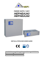
POWER SUPPLY UNIT
HEPHEA242
HEPHEA244
INSTALLATION AND USER GUIDE
ISO9001
Doc. reference
Revision
Pages
Date
Document status
HEPHEA24xR1P04EN
1.04EN
14
29/05/2009
Draft
Editor
Office
C.P.
QC
Approvation
Office
A.S.
PD
EN
HEPHEA242 – HEPHEA244 - Installation and user manual
DOCUMENT’S REVISION
Revision
Date
Description
1.04IT
22/04/09
Translation from the original to the French one.
All
1.04EN
28/08/09
Italian to English tanslation.
All
1
Pages
HEPHEA242 – HEPHEA244 - Installation and user manual
SUMMARY
1
GENERAL SPECIFICATIONS ..................................................................................... 3
1-1
1-2
1-3
1-4
1-5
1-6
2
CONSTRUCTION SPECIFICATION............................................................................. 3
FUNCTIONAL CHARATERISTICS............................................................................... 3
TECHNICAL DETAILED LISTS .................................................................................... 4
PRODUCER’S DECLARATION.................................................................................... 7
SECURITY INFORMATIONS ....................................................................................... 7
LABELING AND IDENTIFICATION OF THE CERTIFIED PRODUCT .......................... 7
INSTALLATION AND CONNECTIONS ....................................................................... 8
2-1
2-1-1
2-2
2-3
2-4
2-5
2-6
POWER SUPPLY BLOCK ............................................................................................ 8
DEVICES AND CONNECTIONS ............................................................................................ 8
NECESSARY TOOLS FOR INSTALLATION .............................................................. 10
WALL MOUNTING...................................................................................................... 10
MAINS CONNECTION................................................................................................ 10
BATTERIES INSTALLATION AND CONNECTION .................................................... 11
CONNECTIONS ......................................................................................................... 12
3
FRONT PANEL SIGNALISATIONS........................................................................... 12
4
PREVENTIVE PERIODIC MAINTENANCE ............................................................... 12
5
ENVIRONMENTAL SPECIFICATIONS ..................................................................... 13
2
EN
HEPHEA242 – HEPHEA244 - Installation and user manual
EN
1 GENERAL SPECIFICATIONS
References HEPHEA242 and HEPHEA244 identify four power supply boxes designed to be appropriate
for the use as power unit with a reserve of energy for the supply of a fire detection installation in
accordance with the Directive of the Products of Construction CPD 89/106/CEE. The electric and
mechanical realization of these products is compliant with the EN standards 54-4:1997 + A1:2002 +
A2:2006, EN12101-10 and EN60950-1:2001.
The equipment can be used in different fields of application from the ones specified provided that the
limits indicated in the paragraphs 1-2 and 1-3 of this document are respected.
1-1 CONSTRUCTION SPECIFICATION
The power supply units AU224K and AU424K use switching technology.
This choice of technology gives the following benefits:
•
A significant reduction of dimensions and weight;
•
An excellent electric efficiency allowing energy saving;
•
An excellent stability in time.
The choice of a toroidal transformer ensures a maximum safety for the operator and the supplied
equipment. The voltages present on all the circuits after the transformer are less than 60V, which
reduces to the minimum the risk of accidental contact with dangerous voltages.
The power supply unit is composed of a metal box, with an index of protection of IP30.It contains the
power supply block and it can receive the lead buffer batteries.
On the box front panel, two indicators (green and yellow) are present for indications of mains power
supply presence and faults. The power supply units have two distinct electronic outputs, with open
collector, for the indication of fault and lack of mains power supply.
There are also 2 relays outputs free of potential for the indication of fault and lack of mains power supply
1-2 FUNCTIONAL CHARATERISTICS
The power supply unit provides a DC voltage ranging between 21V and 28,5V ±2% according to the
operational conditions and the ambient temperature (battery recharge temperature compensated). The
unit is constantly controlled by a microprocessor of last generation which signal a fault condition if one of
the following anomalies is found:
•
•
•
•
•
Battery fuse fault
Damaged battery
Inefficient battery recharge circuit
Mains power supply not present
Output voltage provided by the supply block out of range ( <22,5V o >29,6V ±2%)
Indications are given by the two indicators present on the front panel, each one of them shows 3 states:
ON, OFF and blinking. The main combinations along with their meaning are indicated on the serigraphy
close to the indicators on the front of the box. Those are described on the paragraph 3. The control of
the batteries is carried out periodically (every 4 minutes under normal conditions of operation) by the
power supply unit via a functional test of the battery. To check the battery, the system reduces the
supply voltage of the sector by carrying it from 27,5V to 21V and checks at the same time the output
voltage of the battery. If the voltage does not fall below 22,5V the battery is considered as operational, if
it does, then a fault state is considered.
The system verifies also periodically the value of the resistance of the battery and the associated
circuitry, as demanded by the EN54-4/A2; the fault is signalled when the resistance is over 0,8Ω.
3
EN
HEPHEA242 – HEPHEA244 - Installation and user manual
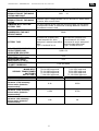
1-3 TECHNICAL DETAILED LISTS
COMMERCIAL DESIGNATION
CONSTRUCTION
CHARATERISTIC
BOX
EXTERNAL DIMENSIONS
WEIGHT (without batteries)
AMBIENT CONDITIONS
COOLING
INSTALLATION LOCAL
GENERAL CHARATERISTICS
HEPHEA242
HEPHEA244
HEPHEA242
HEPHEA244
(27,5Vcc - 2A, metallic box)
(27,5Vcc - 4A, metallic box)
According with EN54-4:1997 + A1:2002 + A2:2006,
EN12101-10 and EN 60950-1:2001
Metal epoxy varnishing; IP protection: IP30
Metallic box CM02: H385 x W405 x D160 mm
Metallic box CM03: H500 x W420 x D200
Rack drawer TR01: H130 x W485 x D265 mm
HEPHEA242: 7 Kg [CM02]
HEPHEA244: 8 Kg [CM02]
-5 °C .. +40 °C,maximum humidities 93%, no condensation
ambiental classes 1 (EN12101-10)
Natural by convection
Inside buildings (protected from climatics modifications)
ELECTRICAL CHARACTERISTICS
HEPHEA242
HEPHEA244
230V +10% / -15%
INPUT VOLTAGE
50Hz sinusoidal
POWER SUPPLY FREQUENCY
MAX CURRENT CONSUMED
550 mA
1,1A
ON MAINS
80VA primary 230V, secondary 150VA primary 230V, secondary
SECURITY TRANSFORMER
34V
34V
Switching PWM BUCK with at 50kHz commutation frequency and
REGULATION TYPE
security transformer for isolation from mains
Included µP control, with possibility to synchronize the battery test
CONTROL TYPE
by external command
NUMBER OF AVAILABLE
2 protected by independent fuses
OUTPUTS
min=21V±2% max=28,5V±2% (available voltage on the output, on
OUTPUT VOLTAGE
different operational conditions, for the supply of the unit, the
external loads and refill batteries).
<500 mVpp under charging and <800 mVpp under charging and
MAXIMUM RESIDUAL
supply from mains condition
supply from mains condition
ONDULATION
(<2%)
(<3%)
TYPICAL RESIDUAL
50 mVpp (0.2%)
100 mVpp (0.4%)
ONDULATION
100mA
MINIMUM LOAD
TOTAL AVAILABLE CURRENT
2A
4A
FOR OUTPUT AND BATTERIES
REFILL
MAX AVAILABLE PERMANENT
1,5A
3A
CURRENT FOR THE OUTPUT
MAX AVAILABLE CURRENT
0,5A
1A
FOR THE BATTERY REFILL
4
EN
HEPHEA242 – HEPHEA244 - Installation and user manual
HEPHEA242
RELAY OUTPUT FOR THE
SEGNALATION OF THE MAINS
STATUS AND FAULT
ELECTRONIC OUTPUT FOR THE
SEGNALATION OF THE MAINS
STATUS
COMMAND INPUT FOR THE
BATTERY TEST
HEPHEA244
30V= - 1A
Positive output voltage between 19,2V= and 28,5V= when mains
is active. Max current 10mA.
The input should not be used with a power supply unit that works
in autonomous mode. It works with a voltage between 0 and 5V=.
Surveillance current <1mA.
MAXIMUM CURRENT
ABSORBED BY THE UNIT
WITHOUT MAINS
BATTERY TYPE
MAX ADMISSIBLE RESISTANCE
FOR BATTERIES AND
ASSOCIATED CIRCUITRY
REGULATION MAINS
VARIATIONS (-15%/+10%)
REGULATION LOADS
VARIATIONS (2.5-100%)
PROTECTION OF BATTERIES
POLARITY INVERSION
FUSES:
MAINS INPUT
SECOND. TRANSFORMER
BATTERIES
EXITS 1 AND 2
Maximum available courrent to
guarantee a 72h autonomy
without mains (batteries
recommended)
Maximum available courrent to
guarantee a 30h autonomy
without mains (batteries
recommended)
Maximum available courrent to
guarantee a 4h autonomy
without mains (batteries
recommended)
50mA
HEPHEA242 (metallic box):
2 lead batteries12V 12Ah,
waterproof, material class HB at
least.
Type: YUASA NP12-12
HEPHEA244 (metallic box):
2 lead batteries 12V 24Ah
connected in serial, waterproof,
material class HB at least
Type: YUASA NP24-12
0,8Ω ± 5%
<2%
<2%
Fuse and diode
T0,63A 250V approved
T3,15A 250V approved
T3,15A 250V approved
T1,6A 250V approved
T1,6A 250V approved
T6,3A 250V approved
T6,3A 250V approved
T3,15A 250V approved
HEPHEA242
HEPHEA244
0.1A
0.25A
0.35A
0.75A
1.5A
3A
5
EN
HEPHEA242 – HEPHEA244 - Installation and user manual
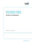
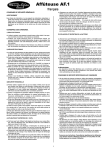
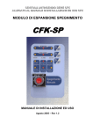
Outputs characteristics
4.5
4
3.5
3
2.5
C.T.
C.U1+C.U2
2
C.B
1.5
1
0.5
0
Distribution of the whole current (C.T.) between outputs (C.U1+C.U2) and batteries (C.B) (HEPHEA244)
2.5
2
1.5
C.T.
1
C.U1+C.U2
C.B
0.5
0
Distribution of the whole current (C.T.) between outputs (C.U1+C.U2) and batteries (C.B) (HEPHEA242)
NOTA : The underlined currents correspond to the minimum necessary values to satisfy the recharge
prescriptions of the batteries indicated by the standard.
30
AS
T.U.
T.B.
25
21
CSU
20
RC
18
16.5
15
LC
10
5
0
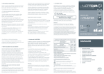
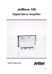
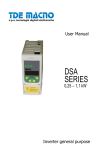
Caratteristiche uscite utilizzatori vs. uscita batterie
LEGGENDA :
AS :
CSU :
RC :
LC :
Mains absence; the difference between the voltage of the outputs and the battery depends to the load applied.
Outputs Isolation o (battery at 21V±5%, consumption <8mA±10%); the outputs are reconnected when mains return
Reduction of the consumption to 3.5mA±10% (18V±5% battery)
Consumption reduced to 500µA±10% (16.5V±5% battery)
6
EN
HEPHEA242 – HEPHEA244 - Installation and user manual
1-4 PRODUCER’S DECLARATION
The producer that developed and produce the power supply unit described in this manual declares that:
•
The project was developed according to an internal quality management system which plans a series
of rules for a correct development of all the subsets of the product.
•
The electric and mechanic project of those products has been developed according to the security
characteristics written in the EN60950-1:2001.
•
All the integrated components were selected in the purpose that them characteristics satisfy the
requirements of the 3K5 of the standard IEC 721-3-3 and what whatever are the internal or external
ambient conditions.
1-5 SECURITY INFORMATIONS
This equipment is intended to be linked with the mains network 230V. To avoid any risk of electric shock,
any interventions must be realized out of mains. Products complies with the standard EN60950-1:2001.
The works with mains voltage active are authorized only for the interventions during which the switch-off
is impossible. The interventions are restricted to qualified technicians only
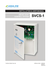
1-6 LABELING AND IDENTIFICATION OF THE CERTIFIED PRODUCT
On the supply units HEPHEA242 and HEPHEA244, on the right external side of the box, is applied the
label that clearly identifies the model, the essential datas and the CE certification according to CPD.
An indication for each model is given below:
HEPHEA242
HEPHEA244
(COD. LOTTO
PRODUZIONE)
Erreur ! Source du
0333
(COD. LOTTO
PRODUZIONE)
Erreur ! Source du
SEFI
SEFI
rue René Cassin - 45300 Pithiviers - FRANCE
rue René Cassin - 45300 Pithiviers - FRANCE
09
0333-CPD-075256
0333
09
0333-CPD-075255
The label characterizes in particular:
a) in the up-left quadrant:
• The identifier name of the product,
• The supply voltage and the maximum current absorbed from the mains,
• The typical nominal output voltage reported to an ambient temperature of 20ºC,
• The maximum current supplied from all parts of the unit,
• The reference to the present installation and user manual;
b) in the up-right quadrant: the object identifier code of production;
c) In the central-right quadrant: the reference European norm for which the product has been certified;
d) In the down-left quadrant: The CE sign with the body number notified at European level that has
release the certification;
e) In the down-right quadrant:
•
•
•
The name and address of the object producer,
At last, two figures refering to the year in which the labeling has been set,
The number of the CE certificate of conformity according to European directive CPD
89/106/CEE.
7
EN
HEPHEA242 – HEPHEA244 - Installation and user manual
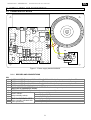
2 INSTALLATION AND CONNECTIONS
2-1 POWER SUPPLY BLOCK
F2
RV2
1
JP2
JP3
F1
1
1 2
F3
2
JP1
F4
RL1
M4
RV1
1 2 3 4 5 6 7 8 9 10 1112
LD1
M1
F5
230V~
RL3
LN
RL2
FUSE
LD2 LD3
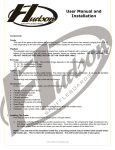
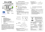
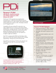
Figure 1 –Power supply blocks AUx24A2
2-1-1 DEVICES AND CONNECTIONS
M1:
1
2
3
4
5
6
7
8
9
10
11
12
SUPPLY OUTPUT N.1 (+): 27,5V ± 1,5% (@ 20°C / 100mA). Output protected by fuse F3
SUPPLY OUTPUT N.1 (-)
SUPPLY OUTPUT N.2 (+):27,5V ± 1,5% (@ 20°C / 100mA). Output protected by fuse F4
SUPPLY OUTPUT N.2 (-)
MAINS PRESENCE ELECTRONIC OUTPUT. Positive voltage output when mains are active
(don’t use in autonomous mode).
EXTERNAL TEST INPUT (don’t use in autonomous mode).
normally open (N.O.)
FAULT RELAY
normally closed (N.C.)
(relay normally active)
common (COM)
RELE’ DI PRESENZA RETE normally open (N.O.)
(relay normally activated with normally closed (N.C.)
mains presence)
common (COM)
8
HEPHEA242 – HEPHEA244 - Installation and user manual
EN
JP3:
1,2 SECONDARY TRANFORMER INPUT 34Vac (protected by fuse F2)
JP1:
1 + OUTPUT FOR BATTERIES: 27,5V ±1,5% (nominal at 20°C without batteries or with batteries
charged at 100%). The output can be disconnected by RL1 under battery fault condition
(batteries voltage < 21V±2%, output voltage < 21V±2%).
2 - OUTPUT FOR BATTERIES
M4:
L, N PIN FOR MAIN INPUT 230V~ +10%/-15% 50Hz
PIN FOR CONNECTION TO ELECTRICAL GROUND
ÍNOTA
Connection with the mains must be carried out by qualified staff and in respect with the usual cares.
Moreover the following criteria must be respected:
a) For the entry and the exit of the cables it is necessary to use distinct holes with press packs.
b) For connection with the mains it is necessary to use suitable cables with a minimum section of
1,5mm² and an inflammability class HB or better.
c) Bare the conductive wires over a length just sufficient enough to allow their insertion in the
corresponding terminals.
d) Insert the conductive wires into the connector blocks and tighten sufficiently. Avoid an excessive
tightening which could damage or cut the conductive wires. Check that all the necessary
conductive wires are inserted inside the terminals.
e) Gather the conductive wires and fix the cables on the appropriated places on the back of the box.
f) The electric cables for the mains must be separated and distant from the electronics parts and
other cables.
g) Carry out and check connection with the ground.
h) Install on the connection upstream, a bipolar device of cut and protection of the mains power
supply.
FUSE FOR BATTERIES PROTECTION T3.15A 250V certified for HEPHEA242 or T6,3A 250V
certified for HEPHEA244.
F2:
FUSE FOR SECONDARY TRANSFORMER PROTECTION T3.15A 250V certified for
HEPHEA242 or T6,3A 250V certified for HEPHEA244.
F3,F4: FUSE FOR OUTPUT PROTECTION 1 and 2 T1,6A 250V certified for HEPHEA242 or T3,15A
250V certified for HEPHEA244.
F5:
FUSE FOR MAINS PROTECTION T0,63A 250V certified for HEPHEA242 or T1,6A 250V
certified for HEPHEA244.
F1:
JP2:
CONNECTION OF LED MODULE FOR FRONT PANEL VISUALISATION.
Visualisation module is provided already connected on JP2 – DO NOT DISCONNECT
LD1:
LD2:
LD3:
LED FOR VISUALIZATION OF THE MAINS PRESENCE. When it is turned on, it means that the
supply unit works with the mains voltage.
LED FOR SIGNALIZATION OF CORRECT OPERATION OF THE SYSTEM. When it is turned
on, it means that there are not failure conditions on the power supply unit.
LED FOR SIGNALIZATION OF BATTERIES DISCONNECTION. When it is turned on, it means
that the unit cut the battery, because of a failure (when there is mains).
RV1: THERMAL COMPENSATION for batteries recharge voltage
RV2: OUTPUT VOLTAGE REGULATION (DO NOT MODIFY)
9
INGRES
COLLEG
EN
HEPHEA242 – HEPHEA244 - Installation and user manual
RL1:
RL2
RL3
RELAY FOR BATTERIES DISCONNECTION
FAULT RELAY. It is activated in condition of no fault presence (positive security), and it is
deactivated when the unit detect any conditions of fault. Max load 1A a 30V=
MAINS RELAY. It is activated when there is mains (positive security) and it is deactivated when
there is’nt any. Max load 1A a 30V=
ÍNOTA The indications N.C., N.O., COM of relais are referred to normal active conditions.
ÍNOTA Only SELV (very low voltage circuits galvanically insulated from other circuit and earth)
circuit can be connected to relais contact.
2-2 NECESSARY TOOLS FOR INSTALLATION
Necessary tools for installation of power supply:
- 4 ankles of suitable size (see below), screw and discs;
- hammer drill with bits for concrete adjusted to the selected ankles;
- 6 mm screwdriver for the fixation of the metal plate necessary to block the batteries.
2-3 WALL MOUNTING
The power supply box must be mounted vertically and fixed on a stable wall adapted to support the
weight of the equipment.
The box is fixed on the wall using four ankles of 8mm, screws and discs of adequate size.
Fixing plates are integrated on the back side of the box to maintain it to a suitable distance from the wall:
Unit
HEPHEA24x
WALL
Figure 2 – Wall mounting
2-4 MAINS CONNECTION
The connection of the block to the mains must be carried out by qualified staff and respecting the usual
cares and the law.
For connection it is necessary to use suitable conductive wires with a minimum section of 1,5mm ² and
holes glands. All the materials used must have a minimum inflammability class of HB.
The conductive wire for the power supply have to be fixed on the back of the box (see Figure 3) on the
dedicated position and has to be separate from the electronic components and input/output cables.
In particular it is necessary to use diferent holes for the cables of the mains electric input and the cables
of the voltage output given by the power supply unit.
It is necessary to install on the upstream of the power supply a differential circuit breaker to protect the
system from an accidental short-circuit to the ground.
ÍNOTA
The cables must not be tinned.
10
EN
LN
HEPHEA242 – HEPHEA244 - Installation and user manual
FUSE
Mains cable
fixation
Figure 3 – Mains cable fixation
2-5 BATTERIES INSTALLATION AND CONNECTION
th batteries must be placed on the bottom of the box and fixed with the safety plate furnished.
A cable is dedicated for the batteries connection, it consists of two conductive wire (a red and a black).
The batteries connection are carried out the following way:
BLACK BATTERY
RED +
BATTERY
+
-
-
+
INTERCONNEXION CABLE
The BLACK conductive wire must be connected on the terminal (-) of the first battery, while the RED
conductive wire must be connected on the terminal (+) of the second battery. The batteries must be
inter-connected together with another cable which connects the terminal (+) of the first battery to the
terminal (-) of the second.
The batteries must be of lead type, waterproof with a capacity ranging between 12Ah and 24Ah
IMPORTANT REMARKS:
a)
b)
c)
Pay attention: not reverse the connections of batteries. A polarity inversion can damage the
equipment.
Connect the batteries only when the installation is ended and all links and insulations are verified.
Use batteries of the same type and with a flammability class UL94-HB or higher.
11
EN
HEPHEA242 – HEPHEA244 - Installation and user manual
2-6 CONNECTIONS
Morsetto
Dettaglio
Tipo di cavo
M4-1
M4-2
M4-3
M1-1
M1-2
M1-3
M1-4
Phase (L), Neutral (N),
Ground ( )
Cable 3 x 1,5mm²
flammability class >HB
Output n°1 (+)
Output n°1 (-)
Output n°2 (+)
Output n°2 (-)
Cable 2 x 1,5mm²
flammability class >HB
Cable 2 x 1,5mm²
flammability class >HB
M1-7
M1-8
M1-9
Fault relay
Cable 2-3 x 0,5mm²
flammability class >HB
M1-10
M1-11
M1-12
Mains presence relay
Cable 2-3 x 0,5mm²
flammability class >HB
3 FRONT PANEL SIGNALISATIONS
The signalisations are made by the means of green and yellow LEDs and present on the front panel are
described on the following table:
GREEN LED
MAINS
YELLOW LED
FAULT
z
z
~
~
{
{
z
z
~
~
{
z
{
{
POWER SUPLLY BLOCK STATE
Normal operation. Mains present, no fault.
Mains present. Monitoring electronic circuit in fault status.
Mains present. Output voltage on fault status (on voltage).
Mains present. Battery switched off or damaged.
Mains not present. Operation under battery supply only.
Mains not present from more than 20 minutes or output voltage
insufficient (operation on batteries supply only)
Mains not present and batteries discharged/disconnected.
Power supply unit disabled.
Legend: z = ON { = OFF ~ = Blinking
4 PREVENTIVE PERIODIC MAINTENANCE
To guarantee the efficiency of the power supply box, the user needs to plan a periodic maintenance
carried out by qualified staff.
The maintenance have to include the control and the tightening of the wires connections and a control of
the voltages provided by the power supply unit for the refill of the battery and the output.
Moreover the effectiveness of the batteries needs to be checked and need to be replaced within the time
recommended by the manufacturer, time which can not be higher than five years.
ATTENTION
For battery replacement use only battery types indicated on this guide.
12
HEPHEA242 – HEPHEA244 - Installation and user manual
EN
5 ENVIRONMENTAL SPECIFICATIONS
In accordance with the European directives, these products must be recycled in specialized places..
Used batteries must be put in the rubbish according to the instructions of recycling indicated by the
manufacturer
13
HEPHEA242 – HEPHEA244 - Installation and user manual
NOTE:
14
EN