1
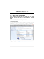
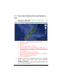
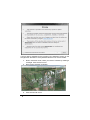
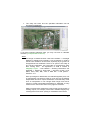
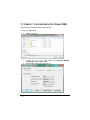
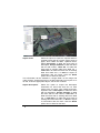
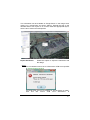
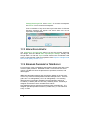
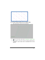
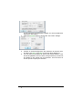
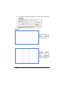
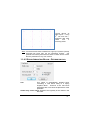
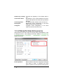
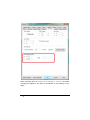
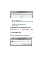
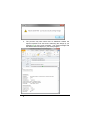
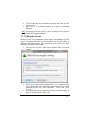
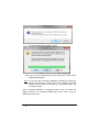
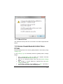
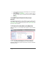
Release Notes IRRICAD Pro Version 14 Developed By Lincoln Agritech Ltd Lincoln Agritech Ltd PO Box 69133 Lincoln Christchurch 7640 Canterbury New Zealand Tel: Fax: (64) 3 325 3718 (64) 3 325 3723 (64) 3 325 3725 © AEI Software 2013. All Rights Reserved ® IRRICAD is a registered trademark of AEI Software This manual was produced using ComponentOne Doc-To-Help.™ Contents Release Notes Pro V14 1 1.1 In Pro Version 14 2 1.1.1 Import from Google Earth 2 1.1.1.1 How To Import Images and Elevations From Google Earth 3 1.1.2 Export to Google Earth File Format (KML) 6 1.1.2.1 Export Settings 7 1.1.3 View in Google Earth 10 1.1.4 Sprinkler Placement in Tree Blocks 10 1.1.4.1 How To Position Block Outlets Using Trees 11 1.1.4.2 Spray Irrigation Block - Options dialog:15 1.1.5 LP Design Pipe Sizing Rationalization 16 1.1.6 Support for Large GIS Coordinates 17 1.1.7 Error Reporting and Recovery Options 19 1.1.7.1 Send Problem Report 19 1.1.7.2 Recovery Options 21 1.1.7.3 Back Up Files 23 1.1.8 Global Change Enabled for Electrical Fittings 23 1.1.9 SHIFT Label Keyword for Valves and Outlets 24 1.1.10 Support for High Resolution Monitors 24 1.1.11 Coordinates Enabled in Fittings errors 24 1.1.12 AutoCAD Compatibility 25 Release Notes IRRICAD Pro Version 14 Contents iii iv Contents Release Notes IRRICAD Pro Version 14 Release Notes Pro V14 Release Notes IRRICAD Pro Version 14 Release Notes Pro V14 1 1.1 IN PRO VERSION 14 1.1.1 IMPORT FROM GOOGLE EARTH Import elevations and images direct from Google Earth from within IRRICAD. The image and data will be geo-located in the IRRICAD design. For the Google Earth feature to work you will need:- Google Earth installed - Microsoft .NET framework Version 4 installed. If you already have this installed you will see it in your Control Panel - Programs and Features:- To update .NET go to http://go.microsoft.com/fwlink/?LinkID=324519 2 Release Notes Pro V14 Release Notes IRRICAD Pro Version 14 1.1.1.1 HOW TO IMPORT IMAGES AND ELEVATIONS FROM GOOGLE EARTH 1. From the File menu, select Import from Google Earth…. The import utility will then start. a. b. c. d. e. Navigation – type general destination name here Go to destination Refresh Check this box to import an image Check this box to use a rectified image – to accurately convert an image from spherical coordinates (latitudes and longitudes) to planar coordinates (X and Y) the image must be re-shaped f. Check this box to import elevation data g. Specify the number of elevations to import – the number of divisions along the largest dimension h. Import action button. 2. Navigate to your area of interest and specify your importation options; Import Image, Rectify Image, Import Elevations, Number of elevations. 3. Click the [Import] button. A disclaimer message will appear for you to read and understand. Release Notes IRRICAD Pro Version 14 Release Notes Pro V14 3 If survey data is available for the property use it instead of relying on the Google Earth elevations. Surveyed data will be much more accurate. 4. Now in selection mode, refine your area of interest by drawing a rectangle. Click the first corner. 5. Drag out the selection rectangle. 6. Click the second corner. 4 Release Notes Pro V14 Release Notes IRRICAD Pro Version 14 7. The utility will close and the specified information will be imported into IRRICAD. If you have imported elevation data, you may now wish to calculate contours (Tools|Calculate Contours). Notes: The image is rotated because it has been rectified - a rectangle defined by latitude and longitude is not rectangular in UTM. It needs to be rectified to be accurate, especially if you go back to Google Earth from IRRICAD. There is an option in the utility to turn off the rectification, but it has little to recommend it other than 'looking nicer'. An explanation of UTM is located in Help|Help Topics – User Manual – Entering Information into IRRICAD -> Entering a Scale Plan -> Importing a DXF, VCD, DWG, GCD, SHP, MIF, CSV or KML File -> GIS options Section 2.4.1.1 Each spot height is determined at a latitude/longitude point, and is subsequently converted to UTM. As such, they are all spatially independent and don’t require rectification. Note that they come from an interpolation in the Google Earth Plugin and will be subject to further interpolation/smoothing by IRRICAD, so they should not be used as the basis of any rigorous solutions. Always double-check dimensions using known world lengths of existing objects, for example, fence lines. Satellite imagery may overlap photos and cause quoting or installation inaccuracies. Release Notes IRRICAD Pro Version 14 Release Notes Pro V14 5 1.1.2 EXPORT TO GOOGLE EARTH FILE FORMAT (KML) Export directly to Google Earth file format KML. To export to KML/KMZ:1. Select File|Export. 2. In the “Save as type” field select the Keyhole Markup Language (*.kml, *.kmz) option. 3. Give the file a name and click [Save]. 6 Release Notes Pro V14 Release Notes IRRICAD Pro Version 14 4. In the KML Import/Export Settings select the required export settings and click [OK]. Import the file into Google Earth. 1.1.2.1 EXPORT SETTINGS Named object name: Select the option to export the required data for items that have zone names (valves and mainline outlets), water supply names, etc. Select Name to label the items with its zone/water supply name, Description to label the items with its description, Unique identifier to label the items with its UID number, Label Set 1 to label the items with its existing label from label set 1, Label Set 2 to label the items with its existing label from label set 2, or None to export no information with the items. This information will be available in Google Earth on the image and under “Places”. Expand the tree on the left-hand side to turn layers on or off and, under the appropriate layers, see the list of names. Named object description: Select the option to export the descriptive information for items that have zone names (valves and mainline outlets), water supply names, etc. Select Name to label the items with its zone/water supply name, Description to label the items with its description, Unique identifier to label the items with its UID number, Label Set 1 to label the items with its existing label from label set 1, Label Set 2 to label the items with its existing label from label set 2, or None to export no information with the items. This information will be available in Google Earth on the image when clicking on a named item and under “Places”. Expand the tree on the left-hand side to turn layers on or off and, under the appropriate layers, see the list of names and descriptions. Release Notes IRRICAD Pro Version 14 Release Notes Pro V14 7 Object name: Select the option to export the required data for hydraulic items that do not have names such as pipes, zone outlets and Misc. Hydraulic items. Select Description to label the items with its description, Unique identifier to label the items with its UID number, Label Set 1 to label the items with its existing label from label set 1, Label Set 2 to label the items with its existing label from label set 2, or None to export no information with the items. Note the Name option has no effect for this field. This information will be available in Google Earth on the image and under “Places”. Expand the tree on the left-hand side to turn layers on or off and, under the appropriate layers, see the list of names. Object description: Select the option to export the descriptive information for items that have do not have names such as pipes, zone outlets and Misc. Hydraulic items. Description to label the items with its description, Unique identifier to label the items with its UID number, Label Set 1 to label the items with its existing label from label set 1, Label Set 2 to label the items with its existing label from label set 2, or None to export no information with the items. Note the Name option has no effect for this field. 8 Release Notes Pro V14 Release Notes IRRICAD Pro Version 14 This information will be available in Google Earth on the image when clicking on a named item and under “Places”. Expand the tree on the left-hand side to turn layers on or off and, under the appropriate layers, see the list of names and descriptions. Export Elevations: Enable this option to export the elevations with the design. Notes: The coordinates need to be in UTM and the UTM zone specified in Settings|Grid/Origin/GIS. The UTM zone grid can be enabled in Google Earth via View | Grid and the correct UTM zone determined. In Release Notes IRRICAD Pro Version 14 Release Notes Pro V14 9 Settings|Grid/Origin/GIS select “North” for northern hemisphere and “South” for the southern hemisphere. If the coordinates of any items are beyond the limits of UTM the following message will appear and those items will not be exported to Google Earth. 1.1.3 VIEW IN GOOGLE EARTH The View|View in Google Earth option is a one step process exporting the design, with the default KML Import/Export Settings, directly into Google Earth. As with the Export to KML function the coordinates need to be in UTM and the UTM zone specified. See Export to Google Earth File Format (KML), Section 7.1.2. 1.1.4 SPRINKLER PLACEMENT IN TREE BLOCKS For many tree crops or plantations the irrigation design starts with a grid of tree or plant positions. IRRICAD Version 14 has a new tool which uses a Tree Block to drive the placement of sprinklers, emitters, and lateral pipes. IRRICAD calculates sprinkler and row spacing based on the tree grid. This is very useful for offset patterns like the example below. The tree grid is 36’ x 30’ triangulated (11m x 9m triangulated). The resulting lateral spacing is 23.0466’ (6.9656m) and the sprinkler spacing is 23.43075’ (7.1063m) with an 18.412% (19.802%) offset. Previously a designer would have had to calculate these values. Now IRRICAD places sprinklers and lateral pipes automatically. The designer specifies sprinkler location by outlets every ‘x’ tree rows and every ‘x’ trees. 10 Release Notes Pro V14 Release Notes IRRICAD Pro Version 14 1.1.4.1 HOW TO POSITION BLOCK OUTLETS USING TREES 1. Draw a tree block, noting the tree row direction. 2. Select the tree block, then select Zone|Spray Irrigation Block ( ). 3. With the block in ‘Use Trees’ mode, the spacing parameters are unavailable. These values will be calculated from the tree spacing. Release Notes IRRICAD Pro Version 14 Release Notes Pro V14 11 If your tree block is significantly irregular, an unconnected block may be the best option. 4. Click the [Options] button to access the ‘Use Trees’ settings. 5. Choose an outlet arrangement, with reference to the tree rows, and then click [OK]. Click [OK] on the main block dialog too. 6. You will then be prompted to specify the lateral direction. This should be parallel to a line of trees, though obviously it need not be parallel to the actual tree row direction. Use the trees as anchor points to specify the direction. 12 Release Notes Pro V14 Release Notes IRRICAD Pro Version 14 7. Next you will be prompted to specify the reference emitter position – click between rows at the approximate height of the required outlet. Once this is specified, IRRICAD will calculate the remaining outlet positions using the pattern entered in Step 6. Release Notes IRRICAD Pro Version 14 Release Notes Pro V14 13 8. The lateral and outlet spacings for the block have now been calculated. Examples: Typical almond tree layout – every row and tree - triangular with 50% offset Typical banana plantation layout – th every 4 row and tree – rectangular with 50% offset and a trenching offset 14 Release Notes Pro V14 Release Notes IRRICAD Pro Version 14 Typical African oil palm layout – every nd 2 row and tree – triangular with 50% offset and a trenching offset Note: If a tree block has been created from a group of symbols (usually imported) the block may not be completely uniform. The sprinkler and lateral placement will work on these blocks unless the tree placement is very non-uniform. 1.1.4.2 SPRAY IRRIGATION BLOCK - OPTIONS DIALOG:- Use: This option is automatically enabled when converting a Tree Block entity to a Spray Irrigation Block. Uncheck if the tree block parameters are not to drive the placement of the sprinklers. Outlet every x tree row(s): Specifies the regularity of the outlets in the tree rows. Release Notes IRRICAD Pro Version 14 Release Notes Pro V14 15 Outlet every x tree(s): Specifies the regularity of the outlets within a row. Tree-to-tree offset: The distance of the outlets between two trees. A 50% offset places the outlet half way between the trees. Trenching Offset: The lateral position distance from the tree row. Rectangular: Rectangular outlet configuration in the block relative to the trees and tree rows. Triangular: Triangular outlet configuration in the block relative to the trees and tree rows. 1.1.5 LP DESIGN PIPE SIZING RATIONALIZATION Improvements have been made to the pipe sizing rationalization of the LP Design process. New settings have been added to Design|Design Parameters|Hydraulic Parameters – Rationalization Parameters to toggle this function. Zone Pipe Sizes: When enabled, sizes will be logically rearranged from large to small, in submains and zone pipes, to produce a more practical arrangement. 16 Release Notes Pro V14 Release Notes IRRICAD Pro Version 14 Mainline Pipe Sizes: The rationalization process occurs after LP Design has selected pipe sizes and set the valve pressure. The resulting arrangement of pipe sizes is then re-analyzed based on the valve pressure already selected. When enabled sizes will be logically rearranged from large to small pipes to produce a more practical arrangement. The rationalization process occurs after LP Design has selected pipe sizes and set the water supply pressure (if not user-defined). The rationalized arrangement of pipe sizes is then re-analyzed based on the water supply pressure already selected. 1.1.6 SUPPORT FOR LARGE GIS COORDINATES When large coordinates exist in an imported plan the “Internal Offset” setting in Settings|Grid/Origin/GIS sets an internal origin based on the location of the imported plan. This setting ensures that at large coordinates the seed tools operate correctly, selecting of items is accurate, and accurate flows are reported in tapes. The “Scale” sets the resolution based on the span of the items on the plan. If the span is great the scale will be greater than 1. If items a distance from the main plan are deleted running Compress and then Repair will adjust the “Scale” to 1. Release Notes IRRICAD Pro Version 14 Release Notes Pro V14 17 When importing files via File|Import or File|Import Contours the below message will appear if the span of coordinates in the drawing is very large:- 18 Release Notes Pro V14 Release Notes IRRICAD Pro Version 14 In this case:1. Turn on all imported layers. 2. Zoom into the plan and using Modify|Select|Window draw a window around the plan. 3. Use Modify|Invert Selection to de-select the plan and select the far-off items. 4. Press the [Delete] key or use Modify|Delete. 5. Run File|Compress. 1.1.7 ERROR REPORTING AND RECOVERY OPTIONS A new feature has been introduced in to IRRICAD Pro Version 14 to streamline information back to the developers regarding a problem design or error information. 1.1.7.1 SEND PROBLEM REPORT Having a problem with a design? Use Help|Send Problem Report, click [Yes] to include your design and your design will be sent to the IRRICAD developers with a log of the tasks you have been performing. 1. Select Help|Send Problem Report and click [Yes] and then [OK] on the messages. Release Notes IRRICAD Pro Version 14 Release Notes Pro V14 19 2. The process may take some time as IRRICAD creates the reports required to be sent and is attaching the design (if you selected [Yes]) to the error message. The email message with the attachments will display in your email program. 20 Release Notes Pro V14 Release Notes IRRICAD Pro Version 14 3. To the email add any information regarding the issue you are experiencing. 4. Click [Send] to complete sending the report to IRRICAD Software. Note: The design must be saved (i.e have a design name) before it can be sent using this method. 1.1.7.2 RECOVERY OPTIONS Should a crash occur (IRRICAD closes down unexpectedly) an error report is prepared and this is easily emailed, via the new utility, to IRRICAD developers along with information about tasks you were performing at the time of the crash. 1. The first time an error crash report appears enter your email address. 2. Each time a crash report appears select [Yes] to attach a copy of the design and enter information about what tasks you were performing when the crash happened. Then click [Send Report]. 3. A message will pop up regarding running your email program in order to send the report. Click [OK]. Release Notes IRRICAD Pro Version 14 Release Notes Pro V14 21 4. A message will appear similar to below Click [Allow] to the complete the process and send the crash report to IRRICAD Software. Note: You can see the information IRRICAD is sending by clicking the “What does this report contain” link in Step 1 above. The email includes an ErrorLog.txt, a Session.log, a crashdump.dmp, and a crashrpt.xml file. Upon re-starting IRRICAD a message similar to the one below will appear. Click [Yes] to reload the design prior to the crash, or [No] to delete the recovery file. 22 Release Notes Pro V14 Release Notes IRRICAD Pro Version 14 1.1.7.3 BACK UP FILES The Autosave back up files are now saved in the DEZ compressed file format. 1.1.8 GLOBAL CHANGE ENABLED FOR ELECTRICAL FITTINGS Electrical fittings items can now be globally added or removed by using Change Type. To use Change Type on electrical junctions to globally add or change fittings:1. Use a Modify|Select tool to select the required electrical junctions and action Modify|Change Type. 2. Click on an electrical junction and click the [Show Fittings] button. 3. Add, change or remove fittings as required and click [Hide Fittings] and then [OK]. 4. In the Match / Change columns Match on “Layer”, especially if zone or mainline junctions are also highlighted. Release Notes IRRICAD Pro Version 14 Release Notes Pro V14 23 5. If only junctions that have the same fittings are to be changed enable Match on “All Fittings”. 6. Enable Change on “All Fittings” so that the changes made to the fittings will be made to all selected items that fit the Match criteria. 7. Click [OK]. 1.1.9 SHIFT LABEL KEYWORD FOR VALVES AND OUTLETS The #SHIFT# label keyword is now enabled for use on control valves and mainline outlets that are not part of an Irrigation Block entity. In Settings|Labels add the #SHIFT# key word to the “Control Valves” text box or the “Outlets” text box. 1.1.10 SUPPORT FOR HIGH RESOLUTION MONITORS IRRICAD Version 14 now includes better support for high resolution monitors. 1.1.11 COORDINATES ENABLED IN FITTINGS ERRORS Reporting of fittings errors has been improved to include the coordinates of problem junctions. 24 Release Notes Pro V14 Release Notes IRRICAD Pro Version 14 1.1.12 AUTOCAD COMPATIBILITY AutoCAD 2013 format files are now imported directly into IRRICAD Version 14. Some improvements have also been made to DXF elevation importation. Release Notes IRRICAD Pro Version 14 Release Notes Pro V14 25


![[1]Oracle® Services Tools Bundle (STB)](http://vs1.manualzilla.com/store/data/005848189_1-e343ea18c466a636d9f3da1a6d7dc0f8-150x150.png)