1
IRRICAD
User Guide
Developed By
Lincoln Agritech Ltd
Lincoln Agritech Ltd
PO Box 69133
Lincoln
Christchurch 7640
Canterbury
New Zealand
Tel:
Fax:
(64) 3 325 3718
(64) 3 325 3723
(64) 3 325 3725
© AEI Software 2013. All Rights Reserved
® IRRICAD is a registered trademark of AEI Software
This manual was produced using ComponentOne Doc-To-Help.™
Contents
1 Overview & Installation
1
1.1 Important Information
1.1.1 Insurance for your IRRICAD
1.2 How to use the Manual
1.3 Installation
1.3.1 Before Installation
1.3.2 Software Installation
1.3.2.1 Digitizer Driver Setup
1.3.2.2 Language Versions
1.4 How to Use Help
1.5 Some Comments for New Users
2
2
4
5
5
7
7
8
10
11
2 User Manual
13
2.1 Introduction
2.1.1 Glossary - Design Terminology
2.1.2 Nomenclature
2.2 Before Starting a Design
2.2.1 Hardware
2.2.1.1 Mouse
2.2.1.2 Mouse Wheel
2.2.1.3 Mouse Settings
2.2.2 Setting Up Defaults
2.2.3 Loading and Setting Up Working Databases
2.2.4 Saving and Backing Up Designs
2.2.5 Using Autocad Colors
2.2.5.1 Mapping Autocad Colors
2.2.6 Usability Features
2.2.6.1 Grouping Items to Display – Using Layers
2.2.6.2 Placement Aids
2.2.6.3 How to Find Lengths and Distances
2.2.6.4 Speeding Up Copy Tools
IRRICAD User Guide
14
14
15
16
16
16
16
17
17
18
19
19
20
20
20
21
27
27
Contents iii
2.2.6.5 Quick Tips
28
2.3 The Design Process
29
2.3.1 The Basic Design Process
29
2.3.2 Details of the Design Process
30
2.3.2.1 Design Details
30
2.3.2.2 Background Information
31
2.3.2.3 Irrigation System Layout
32
2.3.2.4 Management
33
2.3.2.5 Design
35
2.3.2.6 Costing
36
2.3.2.7 Printing and Plotting
36
2.4 Entering Information into IRRICAD
37
2.4.1 Entering a Scale Plan
37
2.4.1.1 Importing a DXF, VCD, DWG, GCD, SHP,
MIF, CSV or KML File
37
2.4.1.2 Importing from Google Earth
44
2.4.1.3 Importing an Image
45
2.4.1.4 Using the Mouse and Keyboard
46
2.4.1.5 Using a Digitizer
47
2.4.1.6 Summary
51
2.4.2 Entering Hydraulic Items
51
2.4.2.1 Item Selection
53
2.4.2.2 Connecting and Placing Hydraulic Items
54
2.4.2.3 Entering Items at Different Levels
56
2.4.2.4 Summary
58
2.4.3 Converting Drawing Items into Hydraulic Entities 59
2.4.3.1 Converting Lines and Points to Pipe and
Outlets
60
2.4.4 Making Changes to the Design or Drawing
60
2.4.4.1 Specifying Groups of Items to Change or
Delete
62
2.4.4.2 Selecting Specific Items – Filtering The
Selection
66
2.4.4.3 Changing Layers
68
2.4.4.4 Creating Staged Developments - Globally
Changing the Scope
69
2.4.4.5 Summary
69
2.4.5 Allowing For Elevation Changes
70
2.4.5.1 Getting Elevation Changes into IRRICAD 71
2.4.5.2 Elevations Along Pipes or Laterals (Uneven
Contours)
71
2.4.5.3 Summary
72
2.4.6 Outlets & Risers (Outlet Connectors)
72
iv Contents
IRRICAD User Guide
2.4.6.1 Arc Types and Nozzle Properties
74
2.4.6.2 Risers (Outlet Connectors)
76
2.4.6.3 Summary
77
2.4.7 Pipes & Pipe Sizing
77
2.4.7.1 Computer Sizing
77
2.4.7.2 Using Cut Pipe
78
2.4.7.3 Summary
80
2.4.8 Entering Control Valves
80
2.4.9 Using Misc. Hydraulic Items
81
2.4.10 Working with Uniformly Spaced Outlets on a Pipe82
2.4.11 Entering Driplines in a Design
84
2.4.12 Using Water Supplies
86
2.4.13 Using Pumps in Design
88
2.4.14 Working with Junctions
90
2.4.15 Defining Areas with Water Requirements
91
2.5 Helping with Design Layout
93
2.5.1 Analyzing Existing Systems
93
2.5.2 Aligning Arcs with Boundaries
95
2.5.2.1 Outlet and Wetted Radii Arc Orientation
96
2.5.3 Using Show Area Tool to Manually Subdivide a
Region
97
2.5.4 Blocks with Automatic Submains and Valve
Placements
98
2.5.4.1 Laterals Tab
99
2.5.4.2 Block Tab
100
2.5.4.3 Flushing Tab
106
2.5.4.4 Interaction with other Tools
107
2.5.4.5 Designing with Block Entities
108
2.5.5 Subdividing Block Entities
108
2.5.5.1 Combining Sub-Areas
110
2.5.5.2 Subdivision Tool Notes
111
2.5.6 How To Position Block Outlets Using Trees
112
2.5.7 How to Layout a Design with Blocks of Laterals
(without using Block Entities)
116
2.5.7.1 Block Properties
117
2.5.7.2 Connecting a Submain (Manifold)
117
2.5.7.3 Tools to Aid in Placing Laterals
118
2.5.7.4 Spray Block Tool
118
2.5.7.5 Tape Block Tool
120
2.5.7.6 Turf
121
2.5.7.7 Horticultural Systems
122
2.5.7.8 Summary
122
IRRICAD User Guide
Contents v
2.5.8 Laying Out Sports Fields or Other Solid Set
Systems
122
2.5.8.1 For rectangular field
122
2.5.8.2 For an oval field
123
2.5.8.3 For an irregularly shaped field:
124
2.5.8.4 Summary
125
2.5.9 Automatically Placing Sprinklers for Small Park or
Residential Design
125
2.5.10 Sprinklers in Odd-Shaped Areas
127
2.5.11 Using Mainline Outlets
127
2.5.11.1 Valve-In-Head Sprinkler Systems
128
2.5.11.2 Stock Water Systems
128
2.5.11.3 Simple Mainline Design - Using Demand
Points
130
2.5.11.4 Summary
130
2.5.12 Wheel Line (Side Roll) Systems
130
2.5.13 Travelling Irrigator Systems
132
2.5.13.1 Placing Each Item
132
2.5.13.2 Combining Hydraulic Properties
133
2.5.13.3 Using Demand Points
134
2.6 Management & Designing the System
135
2.6.1 Selecting a Management Practice
135
2.6.1.1 Assign Zones to System Flows Management135
2.6.1.2 Assign All Zones to One System Flow
Management
140
2.6.1.3 Assign Each Zone to A Unique System Flow
Management
140
2.6.1.4 Other Management Options
140
2.6.2 Partial Management
141
2.6.3 Design
142
2.6.3.1 Nominal Pressures
143
2.6.3.2 Analyze (Existing Sizes)
144
2.6.3.3 Pipe Sizing - LP Design Option
144
2.6.3.4 Pipe Sizing - Velocity Design Option
145
2.6.3.5 Detailed Analysis
146
2.6.3.6 Summary
147
2.6.4 LP Design Limits
147
2.6.5 Flushing Calculations
148
2.6.5.1 Virtual Manifolds
149
2.6.5.2 Manifold Numbering
149
2.6.5.3 Manifold ID Keyword for Labeling Laterals 149
2.6.5.4 How to Use Tape Irrigation Block Flushing
Calculations
150
vi Contents
IRRICAD User Guide
2.6.5.5 Minimum PC Pressure Tape Database Field151
2.6.6 Graphical Reporting Tools
152
2.6.6.1 Graphical Management Symbol
152
2.6.6.2 Graphical Flow or Pressure Maps and
Min/Max Pressure Indicators
152
2.6.6.3 Graphical Elevation Map
153
2.6.6.4 Graphical Hydraulic Gradeline
153
2.6.6.5 Mainline Gradelines
154
2.6.7 IRRICAD Selecting Fittings for the Design
156
2.6.7.1 Manually Adjusting Fittings
156
2.6.7.2 Changing and Fixing Many Fittings Errors in
One Go
158
2.7 Enhancing the Presentation of Plans
159
2.7.1 Placing Symbols on the Plan
159
2.7.1.1 Maintain Shape
159
2.7.1.2 Dynamically Size
159
2.7.2 Making the Database Symbols Larger for Large
Designs or Smaller for Small Designs
160
2.7.3 Using Hatches and Fills
161
2.7.4 Using Dimensions
161
2.7.4.1 Dimension Tab
162
2.7.4.2 Dimension Text Tab
167
2.7.4.3 How to use Linear, Angular, Radial, Diameter
and Ordinate Dimensions
171
2.7.4.4 Datum / Leader Settings
174
2.7.4.5 Using Leader and Datum Dimensions
176
2.7.5 Inserting OLE Data
177
2.7.5.1 OLE Example
178
2.7.6 Automatic Labeling
180
2.7.6.1 Maximum Label Length
182
2.7.6.2 Labels for Multiple Pipes
183
2.7.6.3 Block Labels
183
2.7.6.4 Using Label Sets
184
2.7.6.5 Label Operations
185
2.7.6.6 Database Editor Label Field
185
2.7.6.7 Use Crop Widths
186
2.7.6.8 Label Rounding & Roll Lengths
186
2.7.6.9 Label Alignment
186
2.7.6.10 Design Based Label Settings
187
2.7.7 Creating New Database Symbols
187
2.8 Printing Reports and Plans
188
2.8.1 Producing Reports
188
2.8.1.1 Saving or Exporting Reports
188
IRRICAD User Guide
Contents vii
2.8.1.2 Placing a Report on the Plan
189
2.8.2 How to Print a Plan
189
2.8.2.1 Using Plot Layouts
190
2.8.2.2 Plan Printing
191
2.8.2.3 Exporting to PDF
191
2.9 Advanced Topics
193
2.9.1 Spraylines, Tapes and Minor Losses
193
2.9.1.1 When to Use Connected or Unconnected
Spraylines
193
2.9.1.2 Analysis of Tapes
193
2.9.1.3 Minor Losses Explained
193
2.9.2 How To Simulate Tapes Using Spraylines
194
2.9.2.1 Summary
194
2.9.2.2 Setting up Databases
195
2.9.2.3 Creating the Simulated Design
195
2.9.2.4 Sizing / Analysis
196
2.9.3 Detailed Analysis of Tapes Under Flushing
197
2.9.3.1 Summary
197
2.9.3.2 Setting up Databases
197
2.9.3.3 Creating a Flushing Design
198
2.9.3.4 Flushing Valves
198
2.9.3.5 Sizing Manifolds
199
2.9.3.6 Analysis
199
2.9.4 Modeling Multiple Driplines as a Single Line
200
2.9.4.1 Summary
201
2.9.5 Factors Affecting LP Pipe Sizing
202
2.9.5.1 Drip Tape Design Notes
204
2.9.5.2 Pressure Compensating Design Notes
205
2.9.6 Using a Pump in a Design
206
2.9.6.1 Using Pumps in Parallel
207
2.9.6.2 Pumps in Series
207
2.9.6.3 Miscellaneous Hydraulic Items in The System208
2.9.7 Multiple Water Supplies|keyword=Water
Supplies,multiple
210
2.9.7.1 PRVs with Multiple Water
Supplies|keyword=Water Supplies,prv with
multiple supplies on a System
211
2.9.8 Editing Plot Templates
211
2.9.8.1 Overview
211
2.9.8.2 Creating a New Plot Template
212
2.9.8.3 Creating Legends
213
2.9.8.4 Fills
214
2.9.8.5 Moving Fills to Back
215
viii Contents
IRRICAD User Guide
2.9.8.6 Using Keywords
215
2.9.8.7 Paper Sizes
216
2.9.8.8 How to Edit a Plot Template
217
2.9.9 Advanced Labeling - User Attributes and User
Keyword
219
2.10 Trouble Shooting Problems
222
2.10.1 Design Recovery Options
222
2.10.1.1 Send a Problem Design
222
2.10.1.2 Recovery Options
222
2.10.1.3 How to Recover a Back-up Design
224
2.10.2 Fittings Selection Errors
225
2.10.2.1 General Fittings Selection Errors
225
2.10.2.2 Fittings for Valve-Under-Head Systems 227
2.10.3 LP Design Errors
228
2.10.3.1 Common Error Messages Relating to LP 228
2.10.4 Detailed Analysis Errors
229
2.10.5 Database Issues
230
2.10.5.1 Opening Databases in Microsoft Access 230
2.10.5.2 Updating Pricing / Database Reports
230
2.10.5.3 Read Only files
231
2.10.5.4 Skeleton.mdb
232
2.10.5.5 Merging Databases
232
2.10.5.6 Getting Designs from Someone
232
2.10.5.7 Changing Hydraulic Item Drawing Properties233
2.10.5.8 Updating Internal Database
233
2.10.6 Management Issues
233
2.10.6.1 What Can I Do If Management Has Become
Confused?
233
2.10.7 Connectivity Problems
234
2.10.7.1 Mainline or Zone Items
234
2.10.7.2 The Default Snap Mode
234
2.10.7.3 Limit of Four Items Connecting at a Junction234
2.10.7.4 Snap Tolerance
235
3 IRRICAD Database Editor Manual
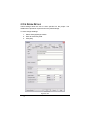
3.1 Using the Database Editor
3.2 Database Structure
3.3 File Menu (Database)
3.3.1 New
3.3.2 Open
3.3.3 Close
3.3.4 Save Copy As
3.3.5 Merge (Databases)
IRRICAD User Guide
237
239
241
243
243
244
244
244
244
Contents ix
3.3.6 Recent File List
3.3.7 Exit
3.3.8 X
3.4 Edit Menu (Database)
3.4.1 Undo
3.4.2 Redo
3.4.3 Undo Record
3.4.4 Cut
3.4.5 Copy
3.4.6 Paste
3.4.7 Copy Component and Paste Component
3.4.8 Find
3.4.9 Replace
3.4.10 Find Next
3.4.11 Find Previous
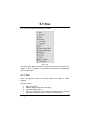
3.5 View Menu (Database)
3.5.1 Curve Fit
3.5.2 Status Bar
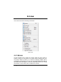
3.6 Component Menu
3.6.1 Add Item
3.6.2 Edit Item
3.6.3 Delete Item
3.6.4 New Assembly
3.6.5 Edit Assembly
3.6.6 Add to Assembly
3.6.7 Remove From Assembly
3.6.8 Finish Assembly
3.6.9 Edit Nozzles
3.6.10 Add Nozzles
3.6.11 Remove Nozzles
3.7 Database Details
3.7.1 Data Common to all Component Groups
3.7.1.1 Item Description
3.7.1.2 Warehouse Code
3.7.1.3 Supplier Code
3.7.1.4 Label
3.7.1.5 Usage code
3.7.1.6 Wholesale Cost
3.7.1.7 Retail Price
3.7.2 Database Codes, Symbols & Line Types
3.7.2.1 Pipe Types
3.7.2.2 Connection Codes
3.7.2.3 Gender Codes
x Contents
245
245
245
246
246
246
246
247
247
247
247
248
248
249
249
250
250
253
255
255
256
256
256
257
257
258
258
258
259
259
260
260
260
260
261
262
262
262
263
263
263
264
264
IRRICAD User Guide
3.7.2.4 Connection Types
3.7.2.5 Database Symbols
3.7.2.6 Symbol and Pipe Colors
3.7.2.7 Line Types
3.7.3 Assemblies
3.7.3.1 About Assemblies
3.7.3.2 Creating Assemblies
3.7.3.3 Example of Assembly Construction
3.8 Irrigation Components – Details of Individual Groups
3.8.1 Pipes
3.8.1.1 Pipe Usage codes
3.8.2 Tapes
3.8.3 Valves
3.8.4 Other Hydraulics
3.8.5 Lateral Take Offs
3.8.6 Couplers
3.8.6.1 End Caps
3.8.7 Elbows / Bends
3.8.8 Tees
3.8.9 Crosses
3.8.10 Pumps
3.8.11 Outlets
3.8.11.1 Demand Points
3.8.11.2 Linking Nozzles to Outlets
3.8.12 Nozzles
3.8.13 Outlet Connections
3.8.14 Wires
3.8.15 Controllers
3.8.16 Lights
3.8.17 Other Electrics
3.8.18 Miscellaneous
3.9 Query Menu
3.9.1 Execute Query
3.9.2 Save Query
3.9.3 Delete Query
3.9.4 Reload Query
3.10 Window Menu
3.10.1 Cascade
3.10.2 Tile
3.10.3 Arrange Icons
3.10.4 Open Databases List
3.11 Tools Menu (Database)
3.11.1 Clean Fields
IRRICAD User Guide
264
265
265
266
266
266
267
267
270
270
270
272
275
276
278
280
281
281
282
284
285
286
289
290
290
293
295
296
297
298
299
301
302
302
302
302
303
303
303
303
303
304
304
Contents xi
3.11.2 Delete Orphan Nozzles
3.11.3 Units
3.11.4 Options
3.11.4.1 Warnings and Errors
3.11.4.2 Application
3.11.5 Customize
3.11.5.1 Toolbars Tab
3.11.5.2 Commands Tab
3.11.5.3 Winicad.ini and Irribase.ini
3.11.6 Language
3.12 Help Menu (Database)
3.12.1 Contents
3.12.1.1 HTML Help
3.12.2 About Irribase
3.13 Advanced Knowledge
3.13.1 Default Database Order
3.13.2 Globally Updating Prices in the Database
3.13.2.1 Fields:
4 Tutorials
315
4.1 Introduction to Design Tutorials
4.1.1 Helpful Hints
4.1.1.1 Terminology
4.1.1.2 On-Line Help
4.1.1.3 Mouse Operation
4.1.2 The First Steps
4.1.3 Important Rules to Remember
4.2 Basic Start
4.2.1 Very Basic Design
4.2.1.1 Starting the Tutorial
4.2.1.2 Drawing the Layout of the System
4.2.1.3 Checking Connections
4.2.1.4 Zone Design
4.2.1.5 Entering Management Requirements
4.2.1.6 Mainline Design
4.2.1.7 Reporting
4.2.2 A Simple Turf Design
4.2.2.1 Getting Started
4.2.2.2 Laying Out the System
4.2.2.3 Checking Connections
4.2.2.4 Zone Design
4.2.2.5 Entering Management Requirements
4.2.2.6 Mainline Design
xii Contents
304
304
305
305
305
306
306
307
307
307
308
308
308
309
310
310
311
312
316
317
317
318
318
319
321
322
322
322
323
324
324
325
325
325
327
327
329
330
331
331
331
IRRICAD User Guide
4.2.2.7 Reporting
332
4.2.3 Methods to Lay Out Sprinklers
332
4.2.3.1 Getting Started
333
st
4.2.3.2 Placing Sprinklers at a Fixed Spacing – 1
Method of Placing Sprinklers at a Fixed
Spacing
333
nd
4.2.3.3 Even Spacing Along a Pipe Length – 2
Method of Placing Sprinklers at a Fixed
Spacing
335
4.2.3.4 Automatically Placing Sprinklers in Irregular
Areas
338
4.2.4 Applying a Specific Amount of Water to an Area 342
4.2.4.1 The Area Dialog
342
4.2.4.2 Calculating Zone Run Times
343
4.3 Design Tutorials
345
4.3.1 Simple Drip Tape Design
345
4.3.1.1 Tapes - An Overview
345
4.3.1.2 Starting the Tutorial
345
4.3.1.3 Checking Connections
348
4.3.1.4 Zone Design
349
4.3.1.5 Entering Management Requirements
350
4.3.1.6 Mainline Design
351
4.3.2 Simple Drip Tape Design Using Block Entities 351
4.3.2.1 Block Entities
351
4.3.2.2 Starting the Tutorial
351
4.3.2.3 Checking Connections
354
4.3.2.4 Zone Design
355
4.3.2.5 Entering Management Requirements
356
4.3.2.6 Mainline Design
357
4.3.2.7 Automatic Labeling
357
4.3.3 A Simple Orchard Design
359
4.3.3.1 Block Entities
360
4.3.3.2 Starting the Tutorial
360
4.3.3.3 Enter Background Information
361
4.3.3.4 Placing the Block
362
4.3.3.5 The Design Process
365
4.3.3.6 Display Reports
368
4.3.4 Working with Multi-Valve Designs
369
4.3.4.1 Getting Started
369
4.3.4.2 Valves Operating Together
372
4.3.5 Micro Irrigation Design
374
4.3.5.1 Starting the Tutorial
374
4.3.5.2 Entering Background Information
375
IRRICAD User Guide
Contents xiii
4.3.5.3 More Background Information
375
4.3.5.4 Creating the Laterals
376
4.3.5.5 Creating the Automatic Submain and Valve378
4.3.5.6 Connecting to the Mainline
380
4.3.5.7 The Design Process
381
4.3.5.8 Making Changes after Initial Designing
384
4.3.5.9 Display Reports
386
4.3.6 Solid Set Sprinkler Design
387
4.3.6.1 Introduction
387
4.3.6.2 Overview
387
4.3.6.3 Starting the Tutorial
388
4.3.6.4 Entering Background Information
388
4.3.6.5 Laying Out Fixed Spaced Outlets
390
4.3.6.6 Designing
393
4.3.6.7 Reporting
395
4.3.7 Residential Design
396
4.3.7.1 Starting the Tutorial
396
4.3.7.2 Background Information
397
4.3.7.3 Placing Sprinklers and Dividing into Zones
within the Available Water Range
401
4.3.7.4 Connecting the System
408
4.3.7.5 The Design Process
409
4.3.8 Wheel Line Design
411
4.3.8.1 Overview
412
4.3.8.2 Starting the Tutorial
413
4.3.8.3 Placing the Wheel Line
414
4.3.8.4 Placing the Hydrants
416
4.3.8.5 Placing the Mainline and Water Supply
417
4.3.8.6 The Design Process
418
4.3.8.7 Computer Selection of Fittings
420
4.3.8.8 Database Items
420
4.4 Mainline Designs
424
4.4.1 Using Demand Points
424
4.4.2 A Rural Water Supply
425
4.4.2.1 Drawing the Layout of the System
425
4.4.2.2 Design
426
4.4.2.3 Variations
427
4.5 Database and Fitting Selection
428
4.5.1 Customizing Your Database
428
4.5.1.1 Entering New Pipes in to the Database
429
4.5.1.2 Entering a New Outlet Into the Database 430
4.5.2 How IRRICAD Selects Fittings and Understanding
the Fitting Selection Rules
433
xiv Contents
IRRICAD User Guide
4.5.2.1 Quick Notes on Making IRRICAD Select the
Fittings You Want
433
4.5.2.2 Using Riser Rules
433
4.5.2.3 Using Pipe Fitting Matching Settings
435
4.5.2.4 Explaining Supplier Codes and Multipliers 436
4.5.3 Correcting Fittings Errors
436
4.5.4 Creating and Modifying Assemblies
438
4.5.4.1 Using Assemblies
438
4.5.4.2 Creating an Assembly
439
4.5.4.3 Modifying an Assembly
441
4.6 Creating and Modifying Symbols
442
4.6.1 Creating New Symbols
442
4.6.2 Modifying an Existing Symbol
444
4.6.3 Setting Up a Block of Symbols
446
4.7 Printing Using Plot Layouts
447
4.8 Digitizing Plans
451
4.8.1 Using the Scale Method
453
4.8.2 The Reference Method
454
4.9 Plot Templates
456
4.9.1 Edit an Existing Plot Template
456
4.9.2 Creating a New Plot Template
457
4.9.2.1 Creating Legends
461
4.9.2.2 Fills
464
4.9.2.3 Moving Fills to Back
465
4.10 Tips for Advanced Users
467
4.10.1 Using a Pump in a Design
467
4.10.1.1 Entering Pumps in to the Database
468
4.10.1.2 Miscellaneous Hydraulic Items in Your
System.
469
4.10.1.3 Draw a Design with a Pump and All
Components
472
4.10.2 Multiple Water Supplies
473
4.10.2.1 PRVs with Multiple Water Supplies on a
System
474
4.10.3 Using Pumps in Parallel
474
4.10.4 Pumps in Series
475
5 Tool and Command Reference
5.1 Right-click menus
5.1.1 Done
5.1.2 Restart
5.1.3 Snaps
5.1.3.1 Place
IRRICAD User Guide
477
478
479
480
480
481
Contents xv
5.1.3.2 Midpoint
5.1.3.3 Endpoint
5.1.3.4 Perpendicular
5.1.3.5 Percent
5.1.3.6 Object
5.1.3.7 Intersection
5.1.3.8 Tangent
5.1.3.9 Closest
5.1.3.10 Center
5.1.3.11 Quadrant
5.1.3.12 Parallel
5.1.4 Zooms
5.1.5 Default Name
5.1.6 Object Info
5.1.6.1 Hydraulic Object Info
5.1.7 Undo Vertex
5.1.8 Modify
5.1.9 Close
5.1.10 Layers
5.1.11 Stop
5.2 Keyboard Commands
5.3 File
5.3.1 New
5.3.2 Open…
5.3.3 Save
5.3.4 Save As…
5.3.5 Import…
5.3.6 Import Contours
5.3.6.1 To Import Elevations from a DXF File:
5.3.6.2 To Import Elevations from a SHP File:
5.3.6.3 To Import Elevations from a CSV, TXT or
XYZ File:
5.3.7 Import Image
5.3.7.1 Show Preview
5.3.7.2 Save Current Path
5.3.7.3 Image Settings
5.3.7.4 Changing Settings After Placement
5.3.8 Import from Google Earth
5.3.8.1 Import From Google Earth Dialog
5.3.9 Export…
5.3.9.1 Export to Google Earth File Format (KML)
5.3.10 Export PDF File
5.3.10.1 Export PDF Dialog
xvi Contents
481
482
482
483
484
484
484
486
486
486
487
487
488
488
488
489
489
489
490
490
491
494
495
495
496
497
498
499
500
501
501
502
504
504
504
506
507
509
509
510
515
515
IRRICAD User Guide
5.3.10.2 Properties Dialog
5.3.10.3 Security Dialog
5.3.11 Export Image File
5.3.11.1 Image Type
5.3.11.2 Settings Dialog:
5.3.12 Repair
5.3.13 Compress
5.3.14 Convert
5.3.14.1 Convert Database
5.3.14.2 Convert Designs
5.3.14.3 Convert Symbols
5.3.14.4 Convert Plot Layouts
5.3.15 Merge
5.3.16 Print…
5.3.16.1 Print Dialog
5.3.17 Direct Plot
5.3.17.1 Plotter Settings
5.3.17.2 Pen Map
5.3.17.3 Language
5.3.18 Reports Print Setup
5.3.19 Recent File List
5.3.20 Exit
5.4 Edit
5.4.1 Undo
5.4.2 Redo
5.4.3 Clear Undo
5.4.4 Paste
5.4.5 Open OLE Item
5.5 View
5.5.1 Redraw
5.5.2 Zoom All
5.5.3 Zoom In
5.5.4 Zoom Out
5.5.5 Zoom Previous
5.5.6 Zoom Window
5.5.7 Zoom Selected
5.5.8 Pan
5.5.9 Dynamic Pan
5.5.10 Goto Coords
5.5.11 Birds Eye View
5.5.12 Toolbars
5.5.12.1 Toolbar Location and Shape
5.5.12.2 Customizing Toolbars
IRRICAD User Guide
518
518
519
520
522
523
524
524
525
525
527
528
529
530
531
534
537
538
538
539
540
540
541
541
542
543
543
544
546
546
547
547
548
548
549
549
550
550
550
551
553
553
553
Contents xvii
5.5.12.3 Current Drawing Properties Toolbar
5.5.13 Status Bar
5.5.13.1 Info Panel
5.5.13.2 Snap Panel
5.5.13.3 Selection Filter Panel
5.5.14 Layer Bar
5.5.14.1 Layers Tab
5.5.14.2 Groups Tab
5.5.14.3 Views Tab
5.5.15 Wetted Radii
5.5.16 Sprayline
Outlets|keyword=Outlets,sprayline+Sprayline
Outlets,viewing
5.5.17 View in Google Earth
5.6 Draw
5.6.1 Point
5.6.2 Line
5.6.2.1 Single Line
5.6.2.2 Double Line
5.6.2.3 Continuous Line
5.6.3 Polyline
5.6.4 Rectangle
5.6.4.1 2 Point Rectangle
5.6.4.2 3 Point Rectangle
5.6.5 Polygon
5.6.5.1 Polygon Dialog
5.6.5.2 Center Polygon
5.6.5.3 Side Polygon
5.6.5.4 Irregular Polygon
5.6.5.5 Seed Polygon
5.6.6 Circle
5.6.6.1 3 Point Circle
5.6.6.2 Diameter Circle
5.6.6.3 Center Radius Circle
5.6.6.4 Ellipse Circle
5.6.7 Curve
5.6.7.1 Single Bezier Curve
5.6.7.2 Continuous Bezier Curve
5.6.7.3 Spline Curve
5.6.8 Arc
5.6.8.1 Start Mid End Arc
5.6.8.2 Center Start End Arc
5.6.8.3 Elliptical Arc
xviii Contents
554
555
555
556
556
557
557
559
560
561
562
562
563
563
564
565
565
567
567
567
568
569
570
571
571
571
572
572
573
574
575
576
576
577
578
578
579
579
580
581
581
IRRICAD User Guide
5.6.9 Hatch
5.6.9.1 Hatch Dialog
5.6.9.2 Hatch Selection
5.6.9.3 Hatch Boundary
5.6.9.4 Hatch Seed
5.6.10 Fill
5.6.10.1 Fill Selection
5.6.10.2 Fill Boundary
5.6.10.3 Fill Seed
5.6.11 Dimension
5.6.11.1 Dimension Settings - Dimension
5.6.11.2 Dimension Settings - Dimension Text
5.6.11.3 Leader / Datum Settings
5.6.11.4 Linear Dimension
5.6.11.5 Angular Dimension
5.6.11.6 Radial Dimension
5.6.11.7 Diameter Dimension
5.6.11.8 Ordinate Dimension
5.6.11.9 Leader Dimension
5.6.11.10 Datum Dimension
5.6.12 Symbol
5.6.12.1 Symbol Dialog
5.6.12.2 Load Symbol
5.6.12.3 Unload Symbol
5.6.13 Text
5.6.13.1 Text Dialog
5.6.14 Plot Layout
5.6.14.1 Plot Layout Dialog
5.6.15 Management Symbol
5.6.16 Pipe Reductions
5.6.17 Tree Block
5.6.17.1 To Create a Tree Block
5.6.17.2 To Modify a Tree Block
5.6.17.3 To Create a Tree Block from an Existing
Array of Symbols/Items
5.6.17.4 Tree Block Dialog
5.6.18 Contour
5.6.18.1 Contour Dialog
5.6.19 Spot Height
5.6.19.1 Spot Heights Dialog
5.7 Zone
5.7.1 Pipe
5.7.1.1 Pipe Dialog
IRRICAD User Guide
582
582
583
584
585
585
586
586
587
588
588
592
595
598
599
600
601
601
602
603
603
603
605
606
606
606
609
610
611
612
614
614
615
615
616
619
619
620
621
622
622
623
Contents xix
5.7.2 Sprayline
5.7.2.1 Sprayline Dialog
5.7.3 Tape
5.7.3.1 Tape Dialog
5.7.4 Cut Pipe
5.7.4.1 Cut Pipe Dialog
5.7.5 Spray Block
5.7.5.1 Block Dialog
5.7.6 Tape Block
5.7.6.1 Tape Block Dialog
5.7.7 Area
5.7.7.1 Area Dialog
5.7.8 Spray Irrigation Block
5.7.8.1 Drawing Properties
5.7.8.2 Laterals tab
5.7.8.3 Options
5.7.8.4 Block Tab
5.7.8.5 Flushing Tab
5.7.8.6 Area Tab
5.7.9 Tape Irrigation Block
5.7.9.1 Drawing Properties
5.7.9.2 Laterals tab
5.7.9.3 Block Tab
5.7.9.4 Flushing Tab
5.7.9.5 Area Tab
5.7.10 Autohead
5.7.11 Junction (Hydraulic)
5.7.11.1 Junction Dialog
5.7.12 Outlet
5.7.12.1 Outlet Dialog
5.7.13 Misc. Hydraulic
5.7.13.1 Misc. Hydraulic Dialog
5.7.14 Control Valve
5.7.14.1 Control Valve Dialog
5.8 Mainline
5.8.1 Water Supply
5.8.1.1 Water Supply Dialog
5.8.2 Pipe (Mainline)
5.8.3 Sprayline (Mainline)
5.8.4 Pump
5.8.4.1 Pump Dialog
5.8.5 Junction (Mainline)
5.8.6 Outlet (Mainline)
xx Contents
624
625
628
628
630
630
631
632
635
636
638
639
641
641
642
644
646
649
652
653
654
654
656
660
662
664
664
665
666
667
669
669
670
671
673
673
674
676
676
677
677
678
679
IRRICAD User Guide
5.8.6.1 Outlet Dialog
5.8.7 Misc. Hydraulic (Mainline)
5.8.8 Control Valve
5.9 Electrical
5.9.1 Light
5.9.1.1 Light Dialog
5.9.2 Wire
5.9.2.1 Wire Dialog
5.9.3 Controller
5.9.3.1 Controller Dialog
5.9.4 Misc. Electrical
5.9.4.1 Misc. Electrical Dialog
5.9.5 Junction (electrical)
5.9.5.1 Junction Dialog
5.10 Settings
5.10.1 Client
5.10.1.1 Client
5.10.2 Company
5.10.2.1 Company
5.10.2.2 Branch
5.10.3 Cursor
5.10.3.1 Cursor Settings:
5.10.3.2 Circular Cursor
5.10.4 Design Details
5.10.4.1 Headings
5.10.4.2 Miscellaneous
5.10.5 Drawing Items
5.10.5.1 Geometric Properties
5.10.5.2 Colors
5.10.5.3 Cursor Settings
5.10.5.4 Miscellaneous Settings
5.10.5.5 Display Settings
5.10.5.6 Ortho Settings
5.10.6 Grid / Origin / GIS
5.10.6.1 Grid
5.10.6.2 Origin
5.10.6.3 GIS Options
5.10.6.4 Internal Offset /Scale
5.10.7 Import/Export Settings
5.10.7.1 DWG Settings Tab
5.10.7.2 DWG Font Import Tab
5.10.7.3 DWG Font Export Tab
5.10.7.4 Color Mapping
IRRICAD User Guide
680
682
682
683
683
683
684
685
686
686
687
688
688
689
691
692
693
693
693
693
694
695
695
696
697
697
697
698
699
699
700
701
701
701
701
702
704
705
705
706
707
708
709
Contents xxi
5.10.8 Irrigation – Design Specific
5.10.8.1 Component Database
5.10.8.2 Spraylines
5.10.8.3 Lines
5.10.9 Irrigation Items
5.10.9.1 Autohead Spacing Limits (%)
5.10.9.2 Flow Check
5.10.9.3 Simplify Contours
5.10.9.4 Contour Simplification Tolerance
5.10.9.5 Database Symbols Path
5.10.9.6 Update Entities from Database
5.10.9.7 Lines
5.10.9.8 Symbols
5.10.10 Labels
5.10.10.1 Properties
5.10.10.2 Labels Text Dialog Properties
5.10.11 Layers
5.10.11.1 Current Layers
5.10.11.2 Layer Manager
5.10.12 Miscellaneous
5.10.12.1 Misc. Company
5.10.12.2 Designer
5.10.12.3 Design Size
5.10.12.4 Undo
5.10.12.5 Miscellaneous
5.10.13 Mouse
5.10.14 Moving Grid
5.10.15 Names
5.10.15.1 Automatic Numbering
5.10.16 Snap
5.10.16.1 Default Snap Mode
5.10.16.2 Running Snaps
5.10.16.3 Tolerances
5.10.17 Units
5.10.17.1 Number Decimal Places
5.10.17.2 Reset to Defaults
5.10.18 Digitizer
5.10.18.1 Tablet Mode
5.10.18.2 Scale
5.10.18.3 Reference
5.10.19 Language
5.11 Modify
5.11.1 Select Object
xxii Contents
711
712
713
713
714
715
715
715
716
716
716
717
717
718
718
721
722
723
724
725
726
727
727
727
727
729
731
731
732
734
734
735
736
737
738
739
739
739
740
741
742
743
744
IRRICAD User Guide
5.11.2 Clear Selection
5.11.3 Invert Selection
5.11.4 Selection Filter
5.11.4.1 Selection Filter Dialog:
5.11.5 Select
5.11.5.1 Select Window
5.11.5.2 Select Crossing
5.11.5.3 SelectLasso
5.11.5.4 Select Last Object
5.11.5.5 Select Adjoining
5.11.5.6 Select Connected
5.11.5.7 Select Screen
5.11.5.8 Select All
5.11.6 Delete
5.11.7 Delete Type
5.11.8 Change
5.11.8.1 Show Fittings
5.11.9 Change Type
5.11.10 Move
5.11.11 Move Point
5.11.12 Copy
5.11.12.1 Linear Copy
5.11.12.2 Radial Copy
5.11.12.3 Array Copy
5.11.12.4 Multiple Copy
5.11.12.5 Mirror Copy
5.11.12.6 Offset Copy
5.11.13 Rotate
5.11.14 Explode
5.11.15 Resize
5.11.16 Break
5.11.17 Scale Image
5.11.18 Z-Order
5.11.19 Trim
5.11.20 Extend
5.12 Tools
5.12.1 Cut Lasso
5.12.2 Trim Spraylines
5.12.3 Move Sizes
5.12.4 Create Wetted Radii
5.12.5 Create Sprayline Outlets
5.12.6 Create Symbol
5.12.7 Calculate Contours
IRRICAD User Guide
745
745
745
746
747
747
748
748
749
749
749
750
750
750
751
751
752
753
754
755
756
756
757
759
760
760
761
762
763
764
765
766
767
767
768
769
769
771
771
772
773
773
774
Contents xxiii
5.12.7.1 Calculate Contours Dialog
5.12.8 Convert to Elevations
5.12.9 Highlight Elevations
5.12.10 Trim Elevations
5.12.11 Create Labels
5.12.12 Update Labels
5.12.13 Spraylines to Tapes
5.12.14 Tapes to Spraylines
5.12.15 Subdivision Tool
5.12.15.1 Slices
5.12.15.2 Cuts
5.12.15.3 Tool Operation
5.12.15.4 Combining Sub-Areas
5.12.15.5 Subdivision Tool Notes
5.12.16 Object Info
5.12.16.1 Hydraulic Object Info
5.12.16.2 Debug Object Info
5.12.17 Insert OLE
5.12.18 Connect Valves
5.12.18.1 Connection Properties
5.12.19 Connect Outlets
5.12.19.1 Connection Properties
5.12.20 Show Area
5.13 Design
5.13.1 Design Parameters
5.13.1.1 Hydraulic Parameters
5.13.1.2 Economic Parameters:
5.13.1.3 Analysis Parameters
5.13.2 Check Outlet Connectivity
5.13.3 Clear Connectivity Marks
5.13.4 Interpolate Elevations
5.13.5 Calculate Elevation Errors
5.13.6 Zone Design
5.13.7 Zone Design Configuration
5.13.7.1 Edit Operations
5.13.8 Valve Specification Summary
5.13.9 Assign Zones to System Flows
5.13.10 Assign All Zones to One System Flow
5.13.11 Assign Each Zone to a Unique System Flow
5.13.12 Clear Management
5.13.13 Other Management Options
5.13.13.1 Water Supply Times
5.13.13.2 Zone Operating Times
xxiv Contents
775
776
777
779
779
780
780
781
781
783
784
785
786
787
788
789
789
789
790
791
792
792
793
794
794
795
797
799
803
803
804
804
805
806
808
809
810
812
813
814
814
814
815
IRRICAD User Guide
5.13.13.3 Assign System Flows to Zones
816
5.13.14 Mainline Design
818
5.13.15 Computer Selection of Fittings
818
5.13.16 Riser Selection Rules
819
5.13.17 Pipe Fitting Matching Table
820
5.14 Reports
823
5.14.1.1 Viewing and Printing Reports
823
5.14.1.2 Setting the Default Printer
824
5.14.1.3 Customizing Reports
825
5.14.1.4 Version 7 Reports
826
5.14.2 Reports Settings
826
5.14.2.1 Text Reports
826
5.14.2.2 Min / Max Pressure Indicators
827
5.14.3 Show Flow
828
5.14.4 View Errors
828
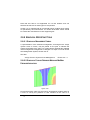
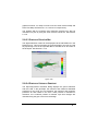
5.14.5 3D DEM View
829
5.14.5.1 Operation
829
5.14.6 Show Zone Pressure Limits
830
5.14.6.1 All Valves
831
5.14.6.2 Selected Valves
831
5.14.6.3 Clear Markers
831
5.14.7 Show Zone Pressure Map
831
5.14.7.1 Selected Valves
831
5.14.7.2 Clear Markers
834
5.14.8 Show Zone Flow Map
834
5.14.8.1 Selected Valve
834
5.14.8.2 Clear Markers
837
5.14.9 Show Allowable Submain Position
837
5.14.9.1 Deciding on Suitable Submain Locations 837
5.14.9.2 How to Operate the Tool
838
5.14.9.3 Allowable Submain Position Dialog
838
5.14.9.4 Notes
839
5.14.10 Hydraulic Gradeline
840
5.14.10.1 Gradeline Toolbar
840
5.14.11 Management Reports
842
5.14.11.1 Water Requirements
842
5.14.11.2 System Flow Report
843
5.14.11.3 Zone Flow Report
844
5.14.12 Zone Design Reports
845
5.14.12.1 Zone Flushing
846
5.14.12.2 Zone Design Summary
847
5.14.12.3 Zone Design Sum. (Uniformity Multi Emit)848
5.14.12.4 Zone Design Summary (Uniformity1 Emit)849
IRRICAD User Guide
Contents xxv
5.14.12.5 Zone Design Pipe Report
5.14.12.6 Zone CV Table
5.14.12.7 Zone Control Valve Summary
5.14.12.8 Zone Design Full
5.14.13 Mainline Design Reports
5.14.13.1 Mainline Summary Report
5.14.13.2 System Duty Report
5.14.13.3 Mainline Design Full
5.14.13.4 ML Design Pipe Report – Nodes
5.14.13.5 Mainline Design Pipe Report
5.14.14 Costing/BOM Reports
5.14.14.1 Zone / Mainline Summary
5.14.14.2 Zone Summary / Mainline BOM
5.14.14.3 Zone / Mainline BOM
5.14.14.4 Zone / Mainline Detailed Costing
5.14.14.5 Inventory by W / H Code
5.14.14.6 Junction BOM
5.14.14.7 Inventory by Description
5.14.14.8 Design Detailed Costing
5.14.14.9 Inventory
5.14.14.10 BOM with Costs
5.14.14.11 Costing Report By Supplier
5.14.14.12 Unconnected Items
5.14.14.13 Design Summary Costing
5.14.14.14 BOM by Supplier
5.14.14.15 BOM
5.14.15 Miscellaneous Costs
5.14.16 Supplier Code Multipliers
5.14.17 Costing Reports Options
5.14.18 Zone Design Reports Configuration
5.14.19 Mainline Design Reports Configuration
5.15 Plot Template
5.15.1 Edit Template
5.15.1.1 Keywords
5.15.2 Make Active Area
5.15.3 Make Legend
5.15.3.1 Legend Dialog
5.15.4 Move Fills to Back
5.15.5 Save Template
5.16 User Tools
5.16.1 Customize
5.17 Help
5.17.1 Release Notes
xxvi Contents
850
851
851
852
855
855
856
856
857
857
858
859
860
860
861
862
862
863
863
864
864
865
866
866
867
868
868
868
870
871
872
874
874
874
875
875
875
876
876
878
878
879
879
IRRICAD User Guide
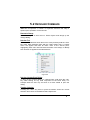
5.17.2 Help Topics
5.17.2.1 HTML Help
5.17.2.2 Hide / Show
5.17.2.3 Back
5.17.2.4 Print
5.17.2.5 Options
5.17.2.6 WinHelp
5.17.3 IRRICAD On The Web
5.17.4 Support Forum
5.17.5 Send Problem Report
5.17.6 About IRRICAD
879
879
880
880
881
881
882
882
882
883
884
6 Technical Reference
885
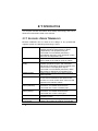
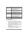
6.1 Technical Support, Sales and Training Services
6.1.1 Contact Details
6.1.1.1 USA, Canada, Central & South America:
6.1.1.2 Australia:
6.1.1.3 Middle East:
6.1.1.4 Europe, North Africa, Turkey and Israel
6.1.1.5 Southern Africa
6.1.1.6 New Zealand & the rest of the world:
6.2 Appendix A: IRRICAD Limits
6.3 Appendix B: Design Files
6.4 Appendix C: Hazen-Williams C Values
6.5 Appendix D: Default Database Order
6.6 Appendix E: Available Line Types
6.7 Appendix F: Design Technical Information
6.7.1 Use of Elevations in Design
6.7.2 Zero Flow Pipes
6.7.3 Valve Pressure Calculation
6.7.4 Pipe Diameter Selection
6.7.5 Highly Looped Mainlines
6.8 Appendix G: Fitting Selection Details
6.8.1 Two Pipe Junctions
6.8.1.1 Straight Connections
6.8.1.2 Bent Connections
6.8.2 Three-Pipe Junctions
6.8.2.1 Tee Orientation
6.8.2.2 Diameter Selection
6.8.2.3 Additional Bends
6.8.2.4 Straight Connections
6.8.3 Four-Pipe Junctions
6.8.3.1 Crosses
IRRICAD User Guide
886
886
886
886
887
887
887
888
889
890
892
893
897
900
900
901
902
902
903
905
905
905
906
907
907
908
909
909
909
910
Contents xxvii
6.8.3.2 Two Tees
910
6.8.4 Five-Pipe Junction
912
6.8.5 Angle Tolerance
913
6.8.6 Fittings for Valve-Under-Head Systems
913
6.9 Appendix H: Form of the Equations
914
6.10 Appendix I: Keywords for Labels and Plot Templates915
6.10.1 Label Keywords
915
6.10.2 Plot Template Keywords
919
6.11 Appendix J: Installation procedure for network
operation
922
6.12 Appendix K: ABOS Method Settings
927
6.13 Screen Messages
934
6.13.1 Introduction
934
6.13.2 IRRICAD File Handling Messages
935
6.13.2.1 Difficulty Opening…File
936
6.13.2.2 Difficulty Reading…File
937
6.13.2.3 Difficulty Writing to…File
938
6.13.3 Error Messages
938
Index
xxviii Contents
993
IRRICAD User Guide
1 Overview & Installation
IRRICAD User Guide
Overview & Installation 1
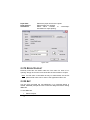
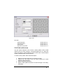
1.1 IMPORTANT INFORMATION
Congratulations on purchasing IRRICAD Pro. We offer upgrades from
time to time that will be downloadable from our website,
www.IRRICAD.com as they come available. We also have a Frequently
Asked Questions section that may help to solve a problem or question
you may have. However, we are always happy to hear from you.
You are also able to download manufacturer's databases from our
website and merge them with your current database or default database.
If you wish a database to be customised specifically for your use,
contact us and we will inform you of the pricing and time frame.
If you have any requests of what you would like to see in IRRICAD in the
future, please let us know. Development for IRRICAD is always on-going
and we will be pleased to be able to meet your needs. Every request is
prioritised according to ease of programming and benefit to the most
users.
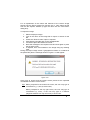
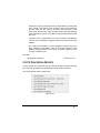
Do you know about the IRRICAD Users Forum?
You can…
Receive up to date announcements from us
Post questions
Help answer other peoples questions
Have your say by making suggestions for future IRRICAD
features
Receive the “Tip of the Week” email notification
1.1.1 INSURANCE FOR YOUR IRRICAD
The hardware key is an integral part of the IRRICAD program and care
should be taken to ensure that it is protected from loss or damage. If the
key is lost as a result of theft, fire or natural disaster it may be replaced
at cost (plus a handling fee) on receipt of an acceptable police or fire
department report. Damaged keys may also be replaced for a similar fee
upon return to your Irricad distributor.
If the key is simply “lost” it does not qualify to be replaced at cost, as this
is in effect the same as the IRRICAD licence being lost which could
subsequently be used by another party. In this case a new licence would
2 Overview & Installation
IRRICAD User Guide
need to purchased and consequently, for your own protection, please
consider insuring the key against accidental loss.
IRRICAD User Guide
Overview & Installation 3
1.2 HOW TO USE THE MANUAL
The manual is divided into several sections: Overview & Installation,
User Manual, Database Editor Manual, Tutorials, Tool & Command
Reference and Technical Reference.
The Overview & Installation section (this section) explains how to install
the program, describes how to use the online help and has comments
for new users.
The User Manual describes how to use the various tools, available in
IRRICAD, to design irrigation systems. It explains how to layout different
system types and includes tips on efficient ways of drawing or changing
items.
The Database Editor Manual explains the use of the database editor,
how to enter and modify items, merge databases and setup databases
so that IRRICAD designs may be completed including the selection of
fittings.
The Tutorials section includes tutorials illustrating the design of several
types of irrigation system. The aim is to give step-by-step instructions to
help to become familiar with IRRICAD. Tutorials are also included to
describe the entry of items in to the database, creating custom symbols
and printing designs. These tutorials are also available in video format
located on the Installation CD. (See Some Comments for New Users,
Section 1.5).
The Tool & Command Reference outlines the function of each menu
item and dialog field. It also shows the steps required for the mechanical
operation of the tool or command.
The Technical Reference includes information to aid in understanding
how IRRICAD works. Information is included about Hazen-Williams C
Values (used in pipe friction loss calculations), rules used to select
fittings for junctions, IRRICAD program limits, keywords for labels and
plot templates, warning messages and technical descriptions of the
design methods used in IRRICAD.
How to Use Help, Section 1.4 will give some tips on using the On-line
Help.
4 Overview & Installation
IRRICAD User Guide
1.3 INSTALLATION
This chapter contains installation instructions and information about
setting up accompanying hardware.
1.3.1 BEFORE INSTALLATION
Before installing and running IRRICAD, please carefully read the
following.
Package Contents
The IRRICAD package supplied should contain:
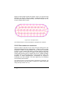
CD-ROM - The IRRICAD program and setup files required to
install and use IRRICAD. Electronic versions of the manual are
included with the software:
User Guide including Overview & Installation, User
Manual,Database Editor Manual and Tutorials.
Reference Manual including Tool & Command Reference
and Technical Reference.
Hardware Key - for new users only.
Protection System
Please read carefully:
IRRICAD software is supplied with a hardware protection device (HPD)
which should be inserted in the USB port of the computer. If required, a
parallel HPD can be provided. The HPD should not interfere with the
running of other packages.
This form of protection has been chosen to provide the user with
maximum flexibility in program use. It permits the user to transport the
package to another machine in the office or to another geographic
location. It does, however, make the HPD an integral part of the
IRRICAD package and accidental loss or theft of the HPD will mean that
IRRICAD cannot be operated.
If the HPD is damaged, return to us an identifiable portion of the HPD
and a replacement will be supplied at cost. Accidental loss or theft of the
HPD may require the purchase of a replacement at the appropriate
discount rate for the total number of IRRICAD programs owned.
IRRICAD User Guide
Overview & Installation 5
Copy and Use Restrictions
Copyright laws protect the software. It is illegal to make copies of the
software except for backups. It is illegal to give copies to another
person, or to duplicate the software by any other means, including
electronic transmission. The software contains trade secrets and the
user may not recompile, reverse engineer, disassemble, or otherwise
reduce the software to human perceivable form. The user may not
modify, adapt, translate, rent, lease, or create derivative works based
upon the software or any part of it.
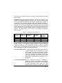
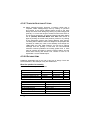
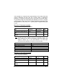
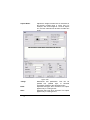
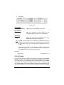
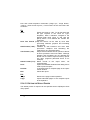
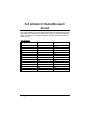
Hardware and Memory Requirements
The following hardware is the minimum recommended for IRRICAD,
although less powerful system configurations may be used for smaller
jobs.
Computer:
Operating System:
Digitizer:
Scanner:
Printers:
Intel i5 or i7 or equivalent processor, minimum
4GB RAM and 250+ GB hard disk, monitor and
video card capable of 512MB video or better,
CD-ROM drive, USB or parallel port.
Windows XP Service pack 3, Windows Vista,
Windows 7 or Windows 8.
To digitize from scaled plans, a digitizer or a
tablet with a WinTab32 driver is required.
Plans and aerial photographs can be scanned
and saved as image files for importing.
IRRICAD can print plans and reports on any
Windows compatible printer.
Color is recommended for plans, although black and white plans can be
produced. At least an ANSI B or A3 printer / plotter is desirable, although
for small plans an ANSI A / A4 printer may be sufficient.
The printer size required will depend on the size of schemes designed
and the size of plan preferred. Large printers have the ability to plot
small plans if required.
A scanner is optional. This can be used to scan in scale plans or
photographs as required.
A digitizer is optional but recommended for those who have access to
any type of scaled plan that can be traced into IRRICAD. These may be
aerial photographs, landscape plans, orchard layouts, subdivision plans,
6 Overview & Installation
IRRICAD User Guide
existing designs, or plans that have been drawn from measurements
taken in the field.
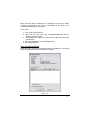
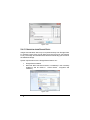
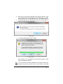
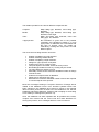
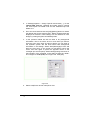
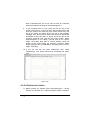
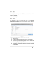
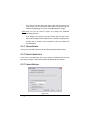
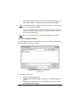
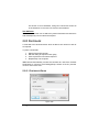
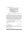
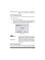
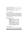
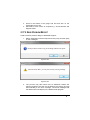
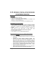
1.3.2 SOFTWARE INSTALLATION
IRRICAD must be installed by using the Setup.exe program file supplied
on the CD-ROM.
1. Log in as an Administrator and open an internet browser (for
example Internet Explorer or FireFox) and browse to an
external website. This step is required for successful
registration of the CAD Engine.
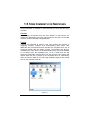
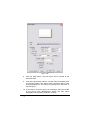
2. Place the CD in the CD-ROM drive. An Autorun executable
should automatically show a dialog containing icons. If Autorun
does not automatically run, browse the CD using My Computer
or Windows Explorer.
3. Close all applications that may be running before installing
IRRICAD.
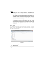
4. To begin the installation process double-click on the Install
IRRICAD icon or open Windows Explorer or My Computer,
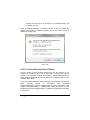
double-click on the CD drive, open the Install folder and doubleclick on Setup.exe. Follow the instructions on the screen to
install IRRICAD on the hard drive.
5. The installation procedure can be cancelled at any time, if so it
will be necessary to double-click on Setup.exe to repeat the
installation.
6. Once the installation is complete run IRRICAD by selecting
Start|All Programs|IRRICAD).
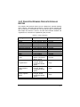
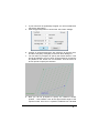
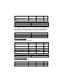
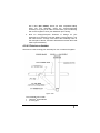
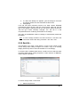
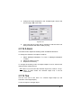
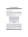
1.3.2.1 DIGITIZER DRIVER SETUP
To use a digitizer, a WinTab driver must be loaded. A WinTab driver can
be obtained from the digitizer manufacturer, the Internet or the hardware
technician. Internet addresses for some common digitizer types:
Calcomp/Summagraphics/GTCO
www.gtcocalcomp.com
Wacom tablets - www.Wacom.com
Kurta or Altek tablets - www.Altek.com
Graphtec tablets - www.Graphteccorp.com
Acecad tablets - www.Acecad.com
IRRICAD User Guide
tablets
-
Overview & Installation 7
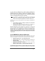
Usually after downloading a file from the Internet, double-clicking on the
file will cause it to self-extract and create a folder for its component files.
There will be a Readme.txt present. Read this file and follow the
instructions for the installation procedure.
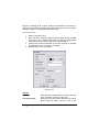
The puck button configurations can usually be accessed and changed in
the Windows Control panel. Select Start | Control Panel and then
double-click on the icon representing the installed tablet. Click on the
[Buttons] button and change as required.
Do not select “Map to Screen” mode. This can also be available as a
check box labeled “Enable Mapping”. The option “WYPIWYG” can also
have the same effect as the above two options. These modes distort the
scale on the screen to match the tablet area.
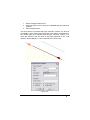
By default the digitizer acts as the standard windows pointing device; to
operate it in the scaled mode in IRRICAD select Settings|Digitizer|Scale
or Settings|Digitizer|Reference.
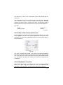
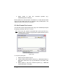
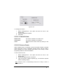
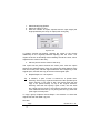
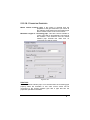
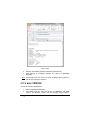
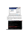
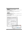
1.3.2.2 LANGUAGE VERSIONS
IRRICAD can be installed in English, French, Spanish, Portuguese or
Hebrew. Select the correct installation file for your required language.
Once installed, the language option may be changed in the
Settings|Language dialog, in the Report Editor or in the error viewer
(Report|View Errors).
The User Interface Language can be independently specified in the
Tools|Language option in the Database Editor.
Plot layouts and report templates are available in English, French,
Spanish, Portuguese or Hebrew and are located in appropriate subfolders
of
the
standard
locations
(e.g.,
IRRICAD
Pro
V13\Symbols\Templates\Spanish, IRRICAD Pro V13\Reports\Spanish).
To enable the use of different layouts or reports (if the language choice
was not selected at installation) the path settings can be found in
Settings|Drawing Items - Miscellaneous. Alternatively the preferred
templates and reports can be copied into the standard locations.
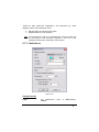
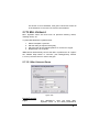
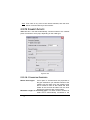
If you have installed IRRICAD without selecting your preferred language
the steps to change the language are:
8 Overview & Installation
IRRICAD User Guide
In IRRICAD:
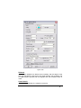
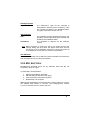
1. Select the required language in Settings|Language.
2. Set the plot layout path in Settings|Drawing Items Miscellaneous “Plot Layout Path” to point to the required
language sub-folder of layouts by clicking the
button.
3. Set the report template path in Settings|Drawing Items
Miscellaneous “Reports Path” to point to the required language
sub-folder of reports by clicking the
button.
In The Database Editor:
1. Select Tools|Language to change the language as required.
IRRICAD User Guide
Overview & Installation 9
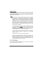
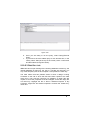
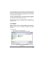
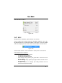
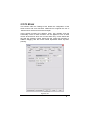
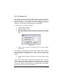
1.4 HOW TO USE HELP
On-line help is a convenient and quick way to look up information whilst
using IRRICAD. Help can be viewed on-line in the following ways:
In any IRRICAD window, press F1 to open the Help Topics
The Help Topics can also be accessed by selecting Help Topics
from the Help menu in the main IRRICAD screen
Information can then be displayed for performing tasks within IRRICAD,
advice on troubleshooting common problems, and technical information
about IRRICAD.
The help file can be loaded as WinHelp or HTML Help. For HTML Help,
Internet Explorer is required.
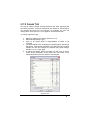
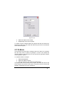
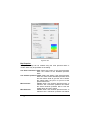
There are three ways in which a topic in the On-line Help may be found:
Contents
Index
Search / Find
Contents
If this tab is selected, the Contents page is displayed. Each heading with
a + sign can be opened to reveal its sub-headings. The sub-headings
can be hidden by clicking on the - sign. Clicking any heading or
subheading will open that section of the manual. The text is displayed on
the right hand side of the help window. If a topic cannot be found in the
Help contents, the Index or Search can be used to look for specific
topics or key words.
Index
Use the Index tab to select an indexed keyword. These words have
been selected to aid in finding specific topics. Select a topic and click the
[Display] button.
Search / Find
Use Search to find a topic. Search lists all the locations the specified
word is found in the on-line help.
10 Overview & Installation
IRRICAD User Guide
1.5 SOME COMMENTS FOR NEW USERS
All documentation is available in both electronic (on-line) and hard copy
manuals.
Overview
It is strongly recommend that the User Manual is read before any
designs are attempted. Doing this will provide the user with an overview
of how to produce a design using IRRICAD.
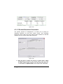
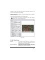
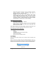
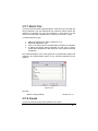
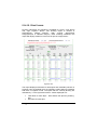
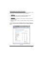
Tutorials
Tutorials are intended to guide a new user through the process of
designing irrigation systems, and accomplishing other tasks, with
IRRICAD. We recommend that the tutorials are completed as a way of
becoming familiar with the design process. The tutorials may also be
available as a video which can be downloaded from the Irricad website
or run directly from the installation CD. To run a video from the CD
select the appropriate tutorial video from the Autorun menu (which will
appear after the CD is placed in the CD-ROM drive) or alternatively
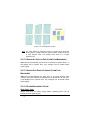
open the “Movie” folder on the CD using Windows Explorer and double
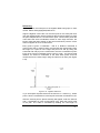
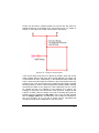
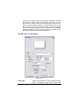
click on the required video file.
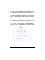
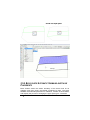
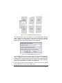
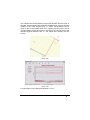
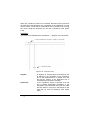
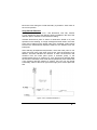
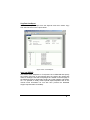
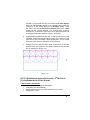
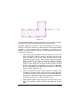
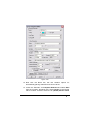
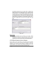
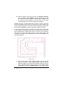
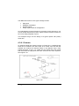
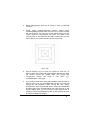
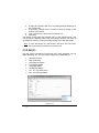
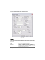
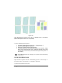
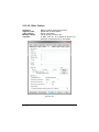
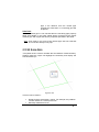
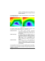
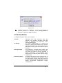
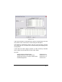
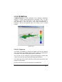
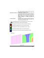
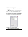
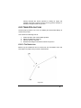
Figure 1-1
IRRICAD User Guide
Overview & Installation 11
12 Overview & Installation
IRRICAD User Guide
2 User Manual
Welcome to the User Manual. This manual is designed to help you
accomplish many tasks common to the design process. Instead of
simply explaining how to use the tools, this manual is intended to help
with understanding the design tasks required and which tools should be
used to complete them.
IRRICAD User Guide
User Manual 13
2.1 INTRODUCTION
This chapter includes information about design terminology and how to
follow the nomenclature used in this manual.
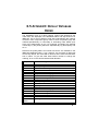
2.1.1 GLOSSARY - DESIGN TERMINOLOGY
Because IRRICAD can be used for the design of any pressurized
irrigation system, the following terminology is used:
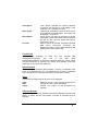
Block:
Control Valve:
Irrigation Block
Entity:
Mainline Pipes:
Mainline Outlets:
Misc. Hydraulic
Items (mainline):
Misc. Hydraulic
Items (zones):
Outlet:
Sprayline
(connected):
14 User Manual
An option for laying out an area of equally
spaced spraylines (Spray Block) or tapes
(Tape Block). The spraylines may be
connected or unconnected (see below).
Immediately after entry, each sprayline or tape
becomes an independent item.
Any device which can be used to control the
flow of water to an outlet or group of outlets.
An option for laying out an area of equally
spaced spraylines or tapes, with automatic
placement of submains, flushing manifolds and
control valves. The spraylines may be
connected or unconnected (see below). Each
block entity is defined as an irrigation zone.
Pipes used to connect zone control valves to
water supplies.
Outlets on a mainline. Each outlet is treated as
a zone and is assumed to also perform the
function of a zone control valve. Valve-in-head
sprinklers are mainline outlets.
Items such as isolating valves, back flow
preventors, air release valves that are
connected into or onto a mainline pipe.
Items such as isolating valves, backflow
preventors, air release valves that are
connected into or onto a Zone pipe.
Any device that discharges water from an
irrigation system.
A zone pipeline containing equally spaced
outlets, also known as a lateral. A connected
IRRICAD User Guide
Sprayline
(unconnected):
System Duty:
Tapes:
Water Supply:
Zone:
Zone Outlets:
Zone Pipes:
sprayline is maintained as a single unit.
A method of spacing outlets uniformly along a
Zone or Mainline pipe. As soon as the
sprayline has been entered it is converted into
individual pipes and outlets, i.e., it is not
maintained as a single unit.
A situation in the mainline (resulting from the
turning on or off of control valves) in which the
flows are fixed for a particular time interval.
Also known as stations, sets or groups.
A lateral with internal emitters (drippers),
commonly called dripline.
A point of supply for the irrigation system.
Items downstream of control valves (including
the valves themselves). A zone becomes
defined when control valves are entered, and
zone pipes or spraylines connected to it,
regardless of how or when those spraylines,
pipes and outlets were entered.
Outlets within a zone.
Pipes used to connect zone outlets to zone
control valves. Also known as submains.
2.1.2 NOMENCLATURE
The following conventions are used in this manual:
When directed to select a command from a menu, the menu
name, menu option and sub menu option (if applicable) will be
listed. For example, Settings|Digitizer|Scale. This refers to
selecting the Scale option from the Digitizer submenu that is
found in the Settings menu. The Settings menu is found on the
menu bar at the top of the IRRICAD window.
When directed to click on a button on a dialog or message on
the screen, the button will be displayed in square brackets; e.g.,
[Save as Defaults].
When directed to press a key on the keyboard, the key will be
displayed in angle brackets; e.g., <Shift> key
Any measurements will be given in US units first and the metric
unit will be supplied in brackets e.g., 300ft (91.5m).
IRRICAD User Guide
User Manual 15
2.2 BEFORE STARTING A DESIGN
2.2.1 HARDWARE
2.2.1.1 MOUSE
IRRICAD uses the mouse installed with Windows operating systems.
Clicking the right mouse button will bring up additional menus of choices
for aiding or finishing tasks when using tools.
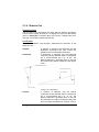
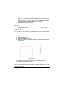
2.2.1.2 MOUSE WHEEL
IRRICAD Pro supports the use of ‘wheel mouse’ devices to both zoom
and pan. Three specific functions are allowed, zoom, pan vertically and
pan horizontally. Each of these functions can be applied to one of three
mouse wheel actions which are: mouse wheel only; mouse wheel with
the shift key pressed; and mouse wheel with the control key pressed. In
addition dragging with the mouse wheel depressed allows ‘dynamic’
panning.
Zoom
By default this function is attached to the Mouse Wheel action. Rotating
the mouse wheel forwards will zoom out while rotating it backwards will
zoom in.
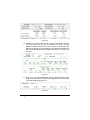
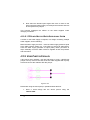
Pan Vertically
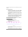
By default this function is attached to the Shift + Mouse Wheel action mouse wheel with the <Shift> key pressed. Rotating the mouse wheel
forwards will move the view of the design up while rotating it backwards
will move it down.
Pan Horizontally
By default this function is attached to the Control + Mouse Wheel
action - mouse wheel with the <Ctrl> key pressed. Rotating the mouse
wheel forwards will move the view of the design to the left while rotating
it backwards will move it to the right.
16 User Manual
IRRICAD User Guide
Note that if the cursor is on a scroll bar then rotating the mouse wheel
pans by moving the scroll bar slider appropriately regardless of whether
the shift or control keys are pressed.
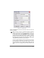
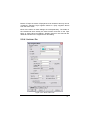
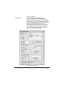
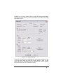
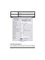
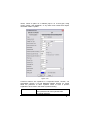
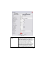
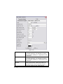
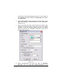
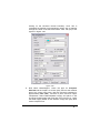
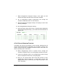
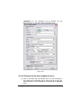
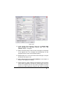
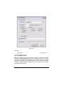
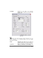
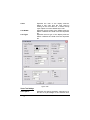
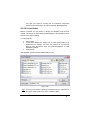
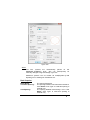
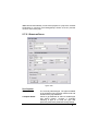
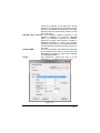
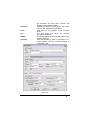
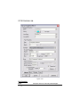
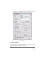
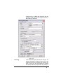
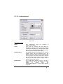
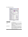
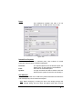
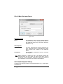
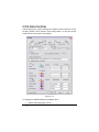
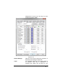
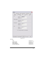
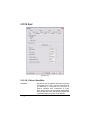
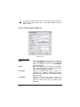
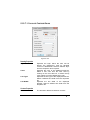
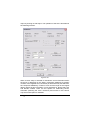
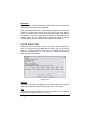
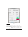
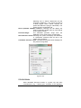
2.2.1.3 MOUSE SETTINGS
This section under the Settings menu allows the configuration of the
wheel mouse and scroll functions.
Zoom
The required mouse wheel action may be selected from the dropdown
menu on the right. If the “Reverse” checkbox is enabled then the effect
of rotating the mouse wheel is reversed relative to the default effect. The
amount of zoom that each mouse wheel ‘click’ represents is controlled
by the “Zoom Factor”. This number is the ratio of the new to the old
zoom state and must be greater than 1 and less than 10. For example
1.5 will give an increase of 50% when zooming out for each wheel click
and a decrease of 1.0/1.5 when zooming in.
Vertical
The required mouse wheel action may be selected from the dropdown
menu on the right. If the “Reverse” checkbox is enabled then the effect
of rotating the mouse wheel is reversed relative to the default effect.
Horizontal
The required mouse wheel action may be selected from the dropdown
menu on the right. If the “Reverse” checkbox is enabled then the effect
of rotating the mouse wheel is reversed relative to the default effect.
Show Scroll Bars
When enabled the scroll bars will be visible.
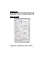
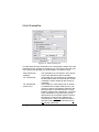
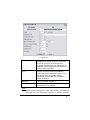
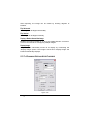
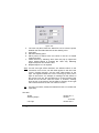
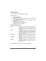
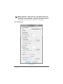
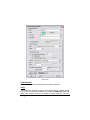
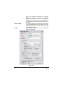
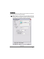
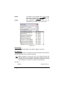
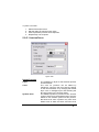
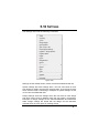
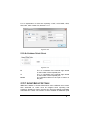
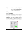
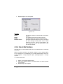
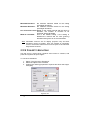
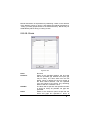
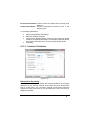
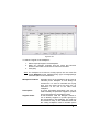
2.2.2 SETTING UP DEFAULTS
Before attempting your own designs, check that the defaults are correct.
The Settings menu allows specification of personal preferences for:
Snaps
Grids
Layers
IRRICAD User Guide
User Manual 17
Drawing values
Units
Design Details
Names
Miscellaneous
Irrigation Items
Irrigation - Design Specific
Company Details
Client Details
When first starting IRRICAD, select Settings|Irrigation Items to change
the default values to those that will apply to all designs. These tend to be
items that once set up are rarely changed.
Settings|Irrigation - Design Specific can be used to set default values for
each design individually. These settings are saved with the design. If
these settings are to be the same for all designs, click the [Save As
Defaults] button.
Hydraulic, economic and other design parameters can be altered in the
Design|Design Parameters dialog. These parameters are design
specific, but can also be saved as the default for all future designs.
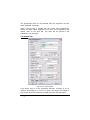
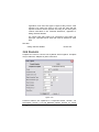
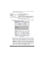
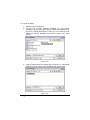
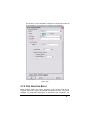
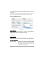
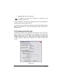
2.2.3 LOADING AND SETTING UP WORKING DATABASES
For each design, IRRICAD requires a database, which contains all the
hydraulic items and their hydraulic properties.
The database loaded during a new installation by default is the working
(external) database.
Before starting the tutorials the tutorial database (provided with the
program) must be selected as the working database. To do this use the
[Browse] button in Settings|Irrigation - Design Specific and locate
Tutorial.mdb in the IRRICAD\database folder. The IRRICAD\database
folder should be opened by default. Click on the Tutorial.mdb file and
click the [Open] button.
To use any other database for a design, select the database in the same
fashion. If the selected database is to be retained as the default
database, click the [Save As Defaults] button.
18 User Manual
IRRICAD User Guide
2.2.4 SAVING AND BACKING UP DESIGNS
It is very important to backup a design regularly both during the design
process and when a design is complete. IRRICAD, like other Windows
programs, keeps the design in memory until File|Save or File|Save As is
selected to save the design to disk.
In Version 13+ the Save option for new designs creates a compressed
archive file (.dez) containing all the constituent design files except the
external database file. To save a design as an older version select
File|Export and select the appropriate file type. Save the file with an
identifying name.
It is a good idea to save the external (working) database with the design
files.
Copies of designs can also be backed up using Windows Explorer or My
Computer by selecting the dez files and copying them to another folder,
a disk, or to a network drive. Repeat to copy the external database,
typically located in the Irricad Pro\database folder, to the disk or network
drive. Alternatively to save the design directly to a disk as a backup
select File|Save As, open the drive and folder, then type in a file name
and click [Save].
If the system crashes (e.g., a power failure) any changes made to the
design since the last File|Save will be lost unless “AutoSave” is enabled.
This is a setting that, if enabled, causes IRRICAD to save the design
periodically to the specified folder (see Settings|Miscellaneous - the
backup folder defaults to IRRICAD\Backup). Note the backup files will
be in compressed format. See How to Recover a Back-up Design,
Section 2.10.1.3.
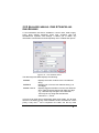
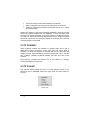
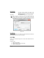
2.2.5 USING AUTOCAD COLORS
IRRICAD loads the colors from the file vga.vcpal (located in the
IRRICAD folder) or, if no file is found, sets up a default palette of colors.
To use an AutoCAD palette instead of the default palette, the following
steps should be followed:
1. Find the file vga.vcpal in the IRRICAD folder using Windows
Explorer.
2. Rename it to Vcadd.vcpal, for example.
IRRICAD User Guide
User Manual 19
3. In the same folder, find either acadwindows.vcpal or
acaddos.vcpal, depending on whether Windows or DOS
AutoCAD colors are required, take a copy and rename it to
vga.vcpal.
Note that changing the palette will affect all designs; even those created
with the old palette will have their colors changed.
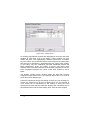
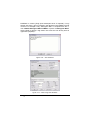
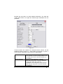
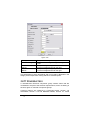
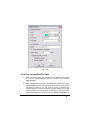
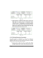
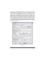
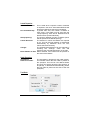
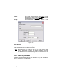
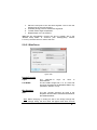
2.2.5.1 MAPPING AUTOCAD COLORS
When importing files IRRICAD maps the color from the DWG/DXF file to
the IRRICAD screen colors, based upon the mapping selected in the
Import/Export Settings under the Settings menu. When using the default
import color map settings this is not necessarily an exact conversion as
it maps to the nearest color however, in the majority of circumstances
this is fine.
If an AutoCAD palette is in use to preserve the color numbers then
‘Custom’ mappings should be setup as follows:
1. In the Color Import tab of Import/Export Settings select the “Use
Custom Map” radio button.
2. Select One to One from the “Map” dropdown box.
3. Repeat this process on the Color Export tab.
For more information see Import/Export Settings, Section 5.10.7.
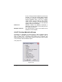
2.2.6 USABILITY FEATURES
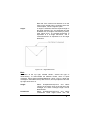
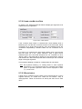
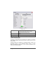
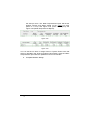
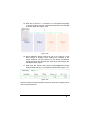
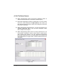
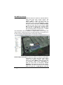
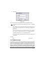
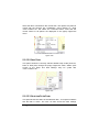
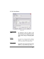
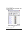
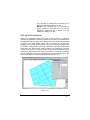
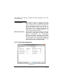
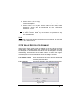
2.2.6.1 GROUPING ITEMS TO DISPLAY – USING LAYERS
IRRICAD automatically groups items in what are called Layers. When
selecting items to place on the screen the resulting dialog will normally
have the layer as <DEFAULT>. This means that all drawing items will be
put into the DRAWING layer, all text is put in the TEXT layer, all pipes
are put in the relevant PIPES layer and all outlets in the OUTLETS layer
unless specified otherwise.
Everything can be placed on one layer or can be stored in related
groups of information on different layers. This is similar to manually
drawing different types of information on the overlay sheets commonly
20 User Manual
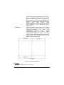
IRRICAD User Guide
used in conventional drafting that can be viewed independently or
stacked on top of one another to compose a complete drawing. For
example, place a basic plan on layer 1, mainline on layer 2, the electrical
system on layer 3, the control valves on layer 4, and so on.
You can create, edit, view, and print any combination of layers together.
Objects can be moved from one layer to another. An object can be
drawn on any layer and with any properties, or can be set to use
properties from the layer itself.
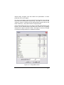
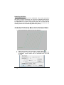
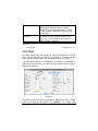
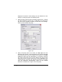
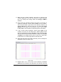
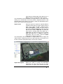
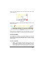
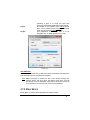
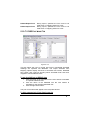
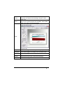
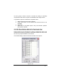
In Settings|Layers a series of larger groups with the <DEFAULT> layer
specified at the top of the dialog can be seen. Notice that the Zone
group is also <DEFAULT>. This means that depending on the item
drawn e.g., an outlet, the item will be put in the correct layer e.g.,
OUTLETS layer. A layer can be selected e.g., TEMPORARY from the
dropdown list so that all zone items will be placed in the TEMPORARY
layer.
New layers can be created and any created layers can be deleted. The
default layers cannot be deleted.
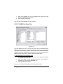
Layers can be turned off (uncheck the check box for that layer in the
“Show” column) to hide the items in them. Items can have their drawing
properties selected as “By Layer”, which means that the item will display
the color, line type and line widths as per the layer defined properties.
These layer properties can be changed by clicking on the “Color” column
to change the color or selecting a new line type and width from the
dropdown lists when clicking in the “Line Type” or “Line Width” column.
Items can also be moved from one layer into another. The main reason
for doing this would be to turn off some items but have other items
remain visible. All visible items are printable. See Changing Layers,
Section 2.4.4.3 to see how to do this.
2.2.6.2 PLACEMENT AIDS
The following placement aids are provided to simplify and speed up
some tasks.
Circular Cursor: Settings|Drawing Items – “Circular Cursor”
Direct Entry: Keyboard
Connecting Hydraulic Items: Settings|Snap
Grid: Settings|Grid / Origin
IRRICAD User Guide
User Manual 21
Snap to Grid: Settings|Snap
Ortho Mode: Settings|Drawing Items – “Ortho”
Snaps: Right-click|Snaps
Running Snaps: Settings|Snap
Circular Cursor Aid
The circular cursor is a tool that can be used to position items a
particular distance from an existing item. A radius is specified, at the
required distance, and the cursor is used as a visual locator to place the
next item.
This tool can be used for all geometric and hydraulic tools.
An example of the use of this tool would be drawing in a block of tapes a
set distance from the fence line.
Sizing and Placing Objects Accurately Using Direct Entry
Distances, angles and co-ordinates can be entered directly by using the
keyboard. As the characters are typed they are displayed on the lefthand side of the status bar. Pressing the <Enter> key executes the
command.
A single number is always a distance; angles require a distance, and coordinates are two numbers divided by a comma. E.g.:
Distance
Distance & angle
Co-ordinates
34
34,<90
0,0
<Enter>
<Enter>
<Enter>
This feature can be used for all geometric objects.
To specify a length of a line, radius, side of a rectangle, etc., select the
tool and place the first click, using the mouse, on the screen (drawing
objects only). Type the length, e.g., 98ft (30m), and press the <Enter>
key. Note prior to pressing the <Enter> key the value typed appears in
the left-hand corner of the status bar.
To specify the angle of a line, radius, side of a rectangle, etc. the length
must be specified. Type in the length, then < and then the angle (e.g.,
o
50,<90 for a line the length of 50ft (m) long at an angle of 90 from the
starting point).
22 User Manual
IRRICAD User Guide
To use co-ordinates to place the start and end points of a line, radius,
side of a rectangle, etc. , type in the required X and Y co-ordinates for
the starting point (e.g., 0,0) and press the <Enter> key. Once again, note
the values typed will appear in the left-hand corner of the status bar.
Now type the X and Y co-ordinates of the end point, (e.g., 50,30) and
press the <Enter> key.
Note: <Num. Lock> may need to be turned off on the keyboard in
order to use the decimal point for metric measurements in the
direct distance entry.
Connecting Hydraulic Items
During the management, design, analysis, and fittings selection
processes IRRICAD needs to “know” how hydraulic items in the system
are connected to each other and subsequently back to control valves or
Water supplies. This list of connections is referred to as the
“Connectivity” and gives rise to a number of rules and mechanisms that
help ensure the correct arrangement of a system.
Pipes, spraylines, and tapes must always directly connect to a point
hydraulic item and not another pipe, sprayline or tape. In the cases
where a water supply, control valve, outlet or miscellaneous hydraulic
item is not present the connection is denoted by a “Junction”, which is
typically displayed as a black square symbol. For example, when a pipe
line changes direction a junction will exist between the two pipes. Free
ends of pipes, spraylines, and tapes are also required to connect to a
junction or a point hydraulic item. Junctions are normally inserted
automatically by the IRRICAD tools and simply serve as internal nodes
for the design process, placeholders for fittings selection, and a location
to display information.
Some consequences of this system are:
Junctions cannot be deleted individually unless unattached.
They will be removed automatically when all connected items
are removed.
Junctions will be removed when point hydraulic objects are
connected to them.
When a point hydraulic item is deleted from a pipe, sprayline, or
tape it will be replaced by a junction.
IRRICAD User Guide
User Manual 23
Hydraulic items can only connect to items of the same class (Zone or
Mainline). The exception is Control Valves which may connect to both
Zone and Mainline pipes.
To assist the user and ensure the correct connectivity the hydraulic
entity creation tools, by default, employ a visually based “connect mode”
(snap). This method uses a user-defined (in Settings|Snap) screen
distance to determine how connections are made to items near the point
clicked. If the screen distance (i.e. in screen millimeters or inches)
between the point clicked, and the nearest hydraulic item, is less that the
setting a connection will be made. Additionally clicking on a pipe,
sprayline or tape, within the setting distance from the end of the item,
will result in the connection being made at the end exactly.
Using this method helps to avoid unwanted small pieces of pipe being
created beyond connections and situations where pipes are not quite
connected to items that they were intended to be. Note that zooming in
before clicking will allow closer (in real terms) connections to be made.
Grid
A grid can be set up to be any spacing desired along the X and Y-axis.
Enter a value for the spacing along the “X”-axis (horizontal) and the “Y”axis (vertical). Enable the “Display Grid Points” if you wish to see the
grid points on the screen. If you have an existing item on the screen and
you wish grid points to be positioned on this item (or corner of the item)
enter the co-ordinates of the item (or corner) into the X and Y fields for
“Grid Origin”.
Snap to Grid
Once a grid has been established you have the option to use
Settings|Snap - “Snap to Grid”. Once “Snap to Grid” is enabled, the
cursor is restricted to only moving between grid points.
This is a very useful tool for drawing straight pipelines, positioning
sprinklers at a specific spacing (without using the Sprayline tool) and for
positioning and drawing geometric objects.
Ortho Mode
Often the work in IRRICAD consists of drawing or editing along
horizontal and vertical axes. This can be achieved by manually entering
coordinates, but it's much quicker to work in “Ortho” mode (see
Settings|Drawing Items Section 5.10.5.6). “Ortho” settings can be used
to constrain point placement so that each point placed is in perfect
24 User Manual
IRRICAD User Guide
horizontal or vertical alignment with the previous point. If only a few
points are going to be entered orthogonally, hold down the <Ctrl> key
while entering the points (if already in “Ortho” mode, using the <Ctrl>
key temporarily turns off “Ortho” mode).
o
o
Although the default orientation of the orthogonal axes is 0 / 90 , these
axes can be rotated to any angle required. This allows you to draw or
edit by placing points that are in 90-degree alignment to one another but
not on the horizontal and vertical axes. To change the angle of the
orthogonal axes, use the “Ortho Angle” setting.
“Ortho Mode” works for both geometric and hydraulic items.
Holding the <Ctrl> key down when in “Ortho Mode” will disengage
“Ortho Mode”. Holding the <Ctrl> key down when not in “Ortho Mode”
will engage “Ortho Mode” using the angle set in the “Ortho Angle” dialog
field.
See also:
Draw
Section 5.6
Accurately Placing Items (Using Snaps)
Perhaps the most important feature of a CAD program is the ability to
place or constrain points in relationship to other elements in the drawing.
IRRICAD offers a complete set of referencing options called snaps.
When a snap option is used while locating a point, the point snaps into
position.
Snaps are tools that allow connecting to existing objects on the screen.
By right-clicking the mouse after having selected a drawing tool the
following snaps are accessed:
Midpoint
Endpoint
Perpendicular
Percent
Object
Intersection
Tangent
Closest
Center
Quadrant
IRRICAD User Guide
User Manual 25
Parallel
The ones most likely to be used on a regular basis are Midpoint,
Endpoint and Perpendicular. By using the Endpoint snap, lines and
geometric objects will connect to the endpoint of an existing object. This
means that the drawing will be tidy. If trying to connect to the end point
of an object by eye, then zoom into this connection it is obvious that the
two objects are quite distant. If the Right-click|Snaps|Endpoint is used,
the two objects are connected. Right-click|Snaps|Midpoint allows
connecting to the middle of an object. Right-click|Snaps|Perpendicular
o
allows connecting to an object at 90 .
For all the snaps, the click must be within a tolerance distance to the
object required to snap to.
When one of the snap tools has been invoked, it will only affect the next
click placed on the screen. If using the same snap for the subsequent
click, it must be selected again, or Running Snaps enabled
(Settings|Snap – [Running Snaps] Section 5.10.16.2).
When drawing hydraulic items on the screen (including Contours and
Spot Heights), the Right-click|Snap|Place tool is the same as setting the
default snap mode to “Place” (rather than “Connect”) but is only active
for the next mouse click. Very useful if placing hydraulic items close the
existing hydraulic items and not wishing them to connect. Note if Place
is selected, hydraulic objects will not be connected together. If a
hydraulic object is not connected, a warning message will be given
during Design.
Snaps selected from the Right-click menu are one-action only. Enabling
Settings|Snap - [Running Snaps] (Section 5.10.16.2 will allow selected
Snaps to be on indefinitely.
For further information about each of the above snaps, see Snaps,
Section 5.1.3.
Running Snaps
Snap tools that are used frequently can be set as running snaps so that
they don't have to be selected repeatedly. Running snaps remain
activated until turned off in the Running Snaps dialog. If the "Show
Preview" option is selected, then when the cursor moves within range of
a point for which a running snap is set, an icon for that snap is displayed
beside the cursor. Running snaps is available for drawing and hydraulic
items. Go to Settings|Snap and click the [Running Snaps] button. You
26 User Manual
IRRICAD User Guide
can select any or all to be on. Remember to check the “RN Snaps On”
check box.
The Snap tools work in much the same way as Connect does. IRRICAD
uses a tolerance range. If an item is within this range then IRRICAD
assumes you wish to snap / connect to this item. The tolerance range is
determined by zoom factor, distance on the screen and world distance.
See also:
Snaps
Running Snaps
Section 5.1.3
Section
5.10.16.2
2.2.6.3 HOW TO FIND LENGTHS AND DISTANCES
On the Status bar right click on the Info Panel (see Section 5.5.13.1) and
select Length. If an item was already highlighted, the length will be
displayed. Any extra items highlighted will show the cumulative length of
all selected items.
Figure 2-1
Use <F9> to measure the length of an object or the distance between
two objects. Hold the cursor over the point to start from and press the
<F9> key. Move the cursor to the point to finish at and read the status
bar. The distance and angle the cursor has moved since pressing <F9>
is displayed.
2.2.6.4 SPEEDING UP COPY TOOLS
When preparing a design it is sometimes necessary to replicate existing
items on a plan. Copy tools allow this to be accomplished and
depending on the tool used, can align and space items as required.
IRRICAD User Guide
User Manual 27
All Copy tools have a 'no dialog' shortcut, which repeats the last copy
without showing the dialog each time.
For example to speed up Offset copy:
1. Draw an arc (for example).
2. Select Offset copy, click the arc and enter a fixed offset distance.
3. Copy the arc to the inside.
4. Offset copy is still selected so, HOLD SHIFT and click the new
arc.
5. Copy the new arc at the same offset, to the inside.
6. HOLDING SHIFT, keep clicking the new arcs to repeat the copy
as many times as required.
Tip:
Be sure to select the Copy tool before clicking on the object. If
the object is selected before the Copy tool is invoked, the tool
will only be active for one action.
2.2.6.5 QUICK TIPS
Default Names
Holding the <Shift> key down when placing a zone valve, mainline outlet
or mainline spraylines doesn't show the “Name” dialog but accepts the
default name.
Saving To Previous Versions of IRRICAD
Designs can be saved in the format of all previous versions of IRRICAD
(to Version 7). See File|Export – “Save as type”.
Toolbars
Any toolbar docking area can be customized by right-clicking on any
icon or toolbar. This is simply a short cut to the View|Toolbars option
and allows immediate customization.
Symbol Colors
Multiple colored symbols can be used in the databases e.g., for Valves.
If a symbol is specified with the "Use symbol color(s)” in the database
editor then the symbol will be displayed in IRRICAD using the colors
contained in the symbol definition.
28 User Manual
IRRICAD User Guide
2.3 THE DESIGN PROCESS
This chapter looks at the basic design process and the details of the
design process.
2.3.1 THE BASIC DESIGN PROCESS
To begin using IRRICAD it is helpful to know the steps that are
necessary to produce a design. Although there is no rigidly prescribed
way of producing designs (this is a major strength of the program), the
following procedure is recommended as a starting point. A basic outline
of the design procedure is:
1. Enter design details.
2. Enter background information - place property boundaries,
buildings and elevation data on the design.
3. Layout the Irrigation System - position water supplies, outlets,
control valves and connect with pipes.
4. Zone Design - hydraulically design and / or analyze from the
control valves to the zone outlets.
5. Management - the operating arrangement, specify which control
valves run together or individually.
6. Mainline Design - hydraulically design and / or analyze the
system from the water supply to the control valves.
7. Costing - select fittings and generate a Bill of Materials and
Costs for clients.
8. Printing - print or plot plans and reports.
IRRICAD User Guide
User Manual 29
2.3.2 DETAILS OF THE DESIGN PROCESS
2.3.2.1 DESIGN DETAILS
Select Settings|Design Headings and enter the design details as
required to specify the design – see Figure 2-2.
Figure 2-2 - Settings Dialog
30 User Manual
IRRICAD User Guide
2.3.2.2 BACKGROUND INFORMATION
Draw in any property boundaries, buildings present on the site, roads
and other topographical features required by using the tools from the
Draw menu. Use the mouse to draw objects or digitize them from a
scaled plan (see Using a Digitizer, Section 2.4.1.5). There are many
other drawing aids that can be used to assist with this process, for
example, Snaps, Snap to Grid, Grid, Circular Cursor, etc.
Elevation data, if applicable, needs to be drawn on or imported into the
design. An existing DXF, SHP, CSV or KML/KMZ file containing
elevation data can be imported into IRRICAD as can background
information in (see Importing a DXF, VCD, DWG, GCD, SHP, MIF, CSV
or KML File, Section 2.4.1.1). Some drawing objects can also be
converted to elevations at a later stage (see Convert to Elevations,
Section 5.12.8). Figure 2-3 shows the contours from an imported DXF
file.
Figure 2-3 - Elevation Data
IRRICAD User Guide
User Manual 31
2.3.2.3 IRRIGATION SYSTEM LAYOUT
The irrigation system can be drawn in any order. However to follow the
progression in the explanation below, we have started with the water
supply end.
Place a water supply (Mainline|Water Supply). Type in any flows or
pressures as provided by the water supply. If these values are left as
zero, then IRRICAD will assume that these values need to be
calculated. Select Mainline|Pipe and connect it to the water supply. For
IRRICAD to size pipes for the system, leave the pipe type as Computer
Selected. For manual sizing, select specific pipes from the dropdown list
and then IRRICAD will analyze the system and report back on system
performance. A combination of computer sized and manually entered
pipes can be used. Pipe sizes can also be selected with the “Computer
Sized” check box enabled so that if the analysis shows a problem then
pipe sizes can be computer sized automatically.
Pipe ends will be automatically connected to other hydraulic items,
providing that they are within the set snap distance and the default snap
mode is “Connect” rather than “Place” (see Default Snap Mode, Section
5.10.16.1).
Figure 2-4 - Irrigation System
A control valve is always used to separate a zone from the mainline.
Select Zone|Control Valve and connect it to the Mainline pipe where it
will be connecting to a zone pipe. Outlets can be placed individually
32 User Manual
IRRICAD User Guide
using Zone|Outlet. Connect outlets using Zone|Pipe. Add any additional
components required (such as backflow preventors, pressure regulating
valves, etc.) as Misc. Hydraulic items. See Using Misc. Hydraulic Items,
Section 2.4.9. Figure 2-4 shows an irrigation system layout.
Pipes and outlets can be treated as a single object using Zone|Sprayline
or Zone|Tape. Multiple spraylines or tapes can be laid out using
Zone|Spray Block or Zone|Tape Block. Blocks can be laid out with
automatic placement of submains, valves, flushing manifolds and
flushing valve assemblies by using the Block Entities of Zone|Spray
Irrigation Block and Zone|Tape Irrigation Block.
2.3.2.4 MANAGEMENT
There are two ways to enter management data for the system:
Graphically by selecting zones on the design to run at any one
time
By filling in a table
Figure 2-5 - Graphical Management
Design|Assign Zones to System Flows allows you to easily and
graphically click on the zones that are to run on a given system flow. It
works by displaying symbols of all zones and water supplies (when there
is more than one) on screen, these symbols can then be selected
IRRICAD User Guide
User Manual 33
individually, or in groups, and assigned to a particular system flow. See
Assign Zones to System Flows, Section 5.13.9.
Design|Assign All Zones to One System Flow and Design|Assign Each
Zone to a Unique System Flow is an automated function to fill in the
Management table for you. See Assign All Zones to One System Flow,
Section 5.13.10 and Assign Each Zone to a Unique System Flow,
Section 5.13.11.
Design|Other Management Options|Zone Operating Times requires
entering operating times for each individual zone in the system. This is
best used for small irrigation systems where actual start and stop times
for valves are important and need to be reported. Based on the
operating times entered, IRRICAD will calculate the resulting flows in the
mainline. This option cannot be used for multiple water supplies. See
Figure 2-6. See Zone Operating Times Section 5.13.13.2.
Figure 2-6 - Zone Operating Times
Design|Other Management Options|Assign System Flows to Zones
allows you to choose the number of system flows and their operating
times and then to select which of the system flows each zone will
operate on. See Figure 2-7. Opening this table will not change any
previously set management. See Assign System Flows to Zones Section
5.13.13.3.
34 User Manual
IRRICAD User Guide
Figure 2-7 - Assign System Flows To Zones
Check all outlets are connected to a valve and all valves are connected
to a water supply (Design|Check Outlet Connectivity).
2.3.2.5 DESIGN
First the zones must be designed. For Computer Selected or
“Computer Sized” pipes in the design run Design|Zone Design|LP
Design. If a system contains loops (closed systems), use Design|Zone
Design|Velocity Design.
If you have selected your own pipe sizes, run
Design|Analyse.
Design|Zone
Take note of any warning messages that may occur. Some messages
are simply warnings to draw your attention, while others terminate the
design process and the reported problem must be rectified before
proceeding. Check the Error Messages, Section 6.13.3 to help pinpoint
the reason for the warning messages.
IRRICAD User Guide
User Manual 35
After successfully running Zone Design any headloss through the valve
is reported in the Zone Design Summary report and the Zone Design
Full report (Reports|Zone Design Reports|...).
After specifying the control valve operating arrangement (management)
run Mainline Design. For Computer Selected or “Computer Sized”
pipes in the design run Design|Mainline Design|LP Design, unless the
design is a looped system or has more than one water supply. In this
case use Design|Mainline Design|Velocity Design. If pipe sizes have
been allocated run Design|Mainline Design|Analyse. Check the Mainline
Design Reports (Reports|Mainline Design Reports|…).
2.3.2.6 COSTING
After successfully running Mainline Design, IRRICAD can automatically
select fittings for the design. To do this, select Design|Computer
Selection of Fittings. IRRICAD will look at each pipe or component
junction in the design and select suitable fittings from the database.
The Bill of Materials (BOM) or Costing reports in the Reports menu can
be viewed to determine if IRRICAD was able to successfully select all
the fittings required. If any problems are found, these can be corrected
by adjusting the database and re-running Fittings Selection or manually
correcting using the Change tool ([Show Fittings] button).
2.3.2.7 PRINTING AND PLOTTING
To print a report first select from the Reports menu and the report will
display in a viewer window. Click the print icon, or select Print from the
File menu in this window.
Predefined plotting layouts can be placed on the plan by selecting
Draw|Plot Layout. These layouts can be moved or altered. Then the final
plan can be printed by selecting File|Print.
See also:
Enhancing the Presentation of Plans
Producing Reports
How to Print a Plan
36 User Manual
Section 2.7
Section 2.8.1
Section 2.8.2
IRRICAD User Guide
2.4 ENTERING INFORMATION INTO IRRICAD
This chapter looks at entering a scale plan, entering hydraulic items,
changing items on the screen, allowing for elevation changes and using
the different types of hydraulic objects in the design.
2.4.1 ENTERING A SCALE PLAN
There are four ways to enter information from a scale plan into
IRRICAD:
By importing a DXF, VCD, DWG, GCD, SHP, MIF, CSV or
KML/KMZ file.
By importing an image file.
By using the mouse or keyboard.
By using a digitizer.
2.4.1.1 IMPORTING A DXF, VCD, DWG, GCD, SHP, MIF, CSV OR
KML FILE
Plans that have been created in other CAD packages can be exported
as a file type that IRRICAD can read (up to Autocad 2013). IRRICAD is
able to import DXF, VCD, DWG, GCD, SHP, MIF, CSV, and KML/KMZ
files. Note that to import contours complete with height data a DXF file,
SHP file, or CSV, TXT, XYZ file that contains Z values (vertex - not
attributes) will be required. The contour layers will need to be specified.
(See Import Contours, Section 5.3.6. Use File|Import Contours and
select the name(s) of the contour layer(s). If a file is imported without
elevations, the Change tool can be used on contours with incorrect
height data or the Convert to Elevations tool can be used on points,
lines, polylines and curves (see Section 5.12.8).
If a file has been acquired in archived form (.zip file), the file will need to
be unzipped before IRRICAD can import it. Files can be extracted from
archives using a utility program (e.g., WinZip, PkZip or 7zip). Windows
XP and higher have inbuilt access to zip archives.
In many cases a DXF or DWG file will be supplied without knowing the
units used when the file was exported (note this does not apply to VCD
or GCD files). Settings|Units has a field labeled “Importing”. Select the
IRRICAD User Guide
User Manual 37
units in which the file was exported as (e.g., m or ft). If this selection is
incorrect, the scale of the imported items will also be incorrect.
To check the scale, find an object in the design of known length in world
units (e.g., ft, m). Place the cursor at one end of the object. Press the
<F9> key to zero the distance on the status bar. Move the cursor to the
other end of the object and look at the ‘d =’ value on the status bar. If the
length of the line is incorrect, start a new design and change the
importing units accordingly. If the file was originally imported in m, and
the length of the object is 3.28 times too long, select ft. Start a new
design and select File|Import or File|Import Contours to re-import the file.
Fonts have been mapped so that most fonts can be displayed in a like
font or mapped to something sensible when a DWG file is imported.
Notes on Internal Offset/Scale
Figure 5-8
When very large coordinates exist in an imported plan IRRICAD attemps
to set an internal origin (viewed in the “Internal Offset” in
Settings|Grid/Origin/GIS) to reduce the magnitude of internal
coordinates. This ensures that the seed tools operate correctly, items
are selected accurately and accurate flows are reported for all tapes.
Addtionally the internal resolution may be set (“Scale” in
Settings|Grid/Origin/GIS) depending on the range of coordinates
spanned by the items on the plan. If the range is large the scale will be
set to 20. Note that running Compress will recalculate the required
scale.
Figure 5-9
38 User Manual
IRRICAD User Guide
When importing files via File|Import or File|Import Contours the above
message will appear if the span of coordinates is too large to be
accommodated by altering the scale:In this case:1. Turn on all imported layers.
2. Zoom into the plan and using Modify|Select|Window draw a
window around the plan.
3. Use Modify|Invert Selection to de-select the plan and select the
far-off items.
4. Press the [Delete] key or use Modify|Delete.
5. Run File|Compress.
Notes on Importing SHP files
ESRI SHP files can now be imported directly into IRRICAD. This facility
works for both normal Import and Import Contours.
Figure 2-10
IRRICAD User Guide
User Manual 39
Text labels are created from the SHP file fields selected in the import
dialog list box. If more than one field is selected, the text is ‘stacked’ in
the label. If the “Import text only” box is checked, only the selected fields
will be imported as text (use this feature if multiple fields are required as
separate labels).
When importing contour / elevation information from an SHP file, you
must select the field which contains the elevation data from the import
dialog list box (see example below).
Figure 2-11
In both SHP importation modes, projected data (latitudes and
longitudes) is accepted if the “UTM WGS84 Projection” has been used.
SHP File Layer Attribute Naming
ESRI Shape files typically contain information which specifies the layer
an object is contained in. In order for IRRICAD to assign objects to the
40 User Manual
IRRICAD User Guide
correct layer the 'attribute', or field name, containing this information
must be specified. Typically the attribute containing the layers is “Layer”,
however in the event this is not the case you can specify the fieldname
containing the layers as shown below.
Figure 2-12
Notes on Importing CSV Files
Drawing and Contour data from CSV files can be imported into
IRRICAD.
The data columns in the file must be arranged in one of the supported
orders (see above). An ID column allows CSV data to be interpreted as
polylines (all points with the same ID form part of the same polyline).
You may uncheck “Import as polylines” to import polyline data as
individual points.
IRRICAD User Guide
User Manual 41
Figure 2-13
Again, latitudes and longitudes are supported using the “UTM WGS84
Projection” only.
To import elevation data as contours an ID column must be included.
The correct option is solely determined by the field order in each
individual file. If receiving files from the same surveyor, once the correct
field order is found, it should not change.
See also:
Import
Import Contours
Section 5.3.5
Section 5.3.6
GIS Options
In order to perform geo-referencing and geo-locating functions IRRICAD
must be able to translate between geographical (latitudes / longitudes)
and planar (X, Y) coordinates. There are many ways to represent both
types of coordinates and IRRICAD uses two of the most common. When
representing geographic coordinates internally IRRICAD uses the
Universal Transverse Mercator (UTM) system. When interpreting
latitudes and longitudes, IRRICAD assumes that they use the World
Geodetic System (1984) (WGS84) reference frame.
UTM divides the northern and southern hemispheres of the Earth into 60
zones and uses a two-dimensional Cartesian coordinate system within
each zone. This means that a UTM coordinate pair is NOT a unique
position on the globe, unlike a latitude and longitude. To fully specify a
UTM position on the globe, one must know to which UTM zone it refers.
42 User Manual
IRRICAD User Guide
Conversion Utility - Why you would convert from WGS84 coordinates to
UTM:This option located in Settings|Grid/Origin/GIS is useful if adding a small
amount of information in to the IRRICAD design. For example a feature
was not previously located on the GPS survey and now you wish to add
it.
From the hand-help GPS unit enter the latitude and longitude in decimal
degrees under WGS84. Click the bottom arrow:
IRRICAD converts the latitudes and longitudes to a coordinate position
on the plan. Using Go To Coords you can now place the feature at the
correct location.
Note: Larger amounts of data can be converted from WGS84 to UTM
by using the existing Import option to import data from a text file
(e.g., CSV).
Notes on Calculated Contours
Calculated contours (secondary elevations) are simply a visual
representation of the underlying primary elevation data (for example
imported spot heights and contours). If for some reason the spot heights
have been removed (this is not recommended), and only the calculated
contours remain, it is not possible to recalculate the DEM if design
changes are required. In this situation in order to assign an elevation to
newly added hydraulic items, or include additional elevation data,
primary elevations are required.
To Change Calculated Contours in to Primary Elevations:1. Draw a contour on the plan using Draw|Contour.
2. Select (highlight) all contours.
3. Select Modify|Change Type and click on the contour just drawn.
Click [OK].
4. In the Change/Match dialog uncheck all items in the "Match"
column and enable "Change" Primary / Secondary Elevation.
Click [OK].
IRRICAD User Guide
User Manual 43
Figure 2-14
2.4.1.2 IMPORTING FROM GOOGLE EARTH
Images and elevation data may be imported directly from Google Earth
by selecting Import from Google Earth from the File menu (see Section
5.3.8). The image and elevation data will be automatically geo-located in
the IRRICAD design.
System requirements for the Google Earth feature are:
Google Earth installed
Microsoft .NET framework Version 4 installed (if this is already
installed it will be visible in Control Panel - Programs and
Features).
Figure 2-15
44 User Manual
IRRICAD User Guide
To update .NET go to http://go.microsoft.com/fwlink/?LinkID=324519
Notes:
By default the resulting image will appear to be slightly rotated.
This is because a rectangle defined by latitude and longitude is
not rectangular in UTM and therefore for accuracy it needs to be
rectified. This is especially necessary if data placed in relation to
the image in IRRICAD is then exported back to Google Earth.
There is an option in the utility to turn off the rectification, but it
has little to recommend it other than 'looking nicer'.
Each spot height is determined at a latitude/longitude point, and
is subsequently converted to UTM. As such, they are all spatially
independent and don’t require rectification. Note that they come
from an interpolation in the Google Earth Plugin, known to be of
low accuracy, and elevations generated from these will be
subject to further interpolation/smoothing by IRRICAD, so they
should not be used as the basis of any rigorous solutions.
Always double-check dimensions using known world lengths of
existing objects, for example, fence lines. Satellite imagery may
overlap photos and cause quoting or installation inaccuracies.
2.4.1.3 IMPORTING AN IMAGE
Aerial photographs of an area can be scanned and saved in one of
several image file formats (BMP, JPG, GIF, TIF, WMF, PCX or PNG for an explanation of the merits and features of the various image
formats see the Export Images – Image Types, Section 5.3.11.1).
Images may also be acquired from online mapping sources, such as
Google Earth. These images can be imported directly in to IRRICAD via
File|Import from Google Earth. See Section 5.3.8.
There are three check boxes along the bottom of the dialog whose
functions are described below:
Image Path
If this box is enabled then the current folder is retained and the next time
Import Image is selected the folder will default to this location.
Use Relative Path
When an Image is imported into IRRICAD a link to the image file is
inserted into the design rather than embedding the entire image. When
IRRICAD User Guide
User Manual 45
“Use Relative Path” is checked the link (i.e., folder path) will be relative
to the location of the IRRICAD design. This feature is very useful if the
design is shifted to another computer, drive or folder. As long as the
image file is located in the same place relative to the design then the link
will be intact and the image will be displayed. Note “Use Relative Path”
cannot be used for an ‘Untitled’ design, if it is, a warning message will be
displayed.
Embed
Images may be embedded in the design. This means that if the design is
sent to another computer, the separate image does not have to be sent
with it – the image is saved in the design itself.
Lock Ratio
If this item is checked, the bitmap rectangle will be constrained to the
aspect ratio (height/width) of the original image during placement. If
unchecked then the image can be drawn so that it may be distorted
compared to the original.
Once the Image file has been selected (by clicking the [Open] button)
the image can be placed on the screen using the mouse or keyboard
entry. The lower-left corner is located first (with a left mouse click or
keyboard coordinates), a rectangle is then drawn out (when using the
mouse the left button should NOT be depressed during this stage) and
then the upper-right corner is placed (note, if the corners are not
specified in lower-left – upper-right order, the image will be flipped
horizontally and/or vertically).
Before importing, the world size of the photograph needs to be known
e.g., the image is 1.5 x 2ft (m) and correlates to a world distance of 3500
x 6000ft (m). Modify|Scale Image can be used to resize the image after
importing. Direct distance entry can also be used to specify the
coordinates of the top left corner and bottom right corner of the image
when importing (see Using the Mouse and Keyboard, Section 2.4.1.4).
2.4.1.4 USING THE MOUSE AND KEYBOARD
The mouse can be used to draw lines or other drawing objects on the
screen. The status bar will display the length of the line before the
second click. The status bar value d = measures from each click used to
place each point of a drawing and hydraulic tool. To measure a distance
or length of an object already on the screen right-click on the Info Panel
46 User Manual
IRRICAD User Guide
of the Status Bar (Section 5.5.13.1) and select Length and then select
any existing item on the screen. Or place the cursor at one end of the
object. Press the <F9> key to zero the distance on the status bar. Move
the cursor to the other end of the object and look at the d = value on the
status bar (note this method is less accurate as it relies on the
placement of the cursor).
Direct Distance Entry
The keyboard can be used to specify lengths, coordinates and angles of
drawing tools. To specify a length of a line, radius, side of a rectangle,
etc., select the tool and place the first click, using the mouse, on the
screen (drawing objects only). Type the length, e.g., 30 (ft, m) and press
the <Enter> key. Note prior to pressing the <Enter> key the value type
appears in the left-hand corner of the status bar.
To specify the angle of a line, radius, side of a rectangle, etc. a length
must also be specified. Type in the length, then <, then the angle (e.g.,
o
50,<90 for a line the length of 50ft (m) long at an angle of 90 from the
starting point).
To use coordinates to place the start and end points of a line, radius,
side of a rectangle, etc., type in the required X and Y coordinates for the
starting point (e.g., 0,0) and press the <Enter> key. Once again, note the
values type will appear in the left-hand corner of the status bar. Now
type the X and Y coordinates of the end point (e.g., 50,30) and press the
<Enter> key.
See also:
Draw
Section 5.6
2.4.1.5 USING A DIGITIZER
The section headed Digitizer Driver Setup, Section 1.3.2.1 gives a brief
outline of setting up and using a digitizer. To recap, a WinTab32 driver
must be loaded, and the digitizer attached to an available
communication port.
In normal drawing mode, the digitizer can be used in exactly the same
way as the mouse to select commands and tools. In Tablet Mode, you
can trace over scale drawings which have been placed on the digitizer
tablet.
IRRICAD User Guide
User Manual 47
Before
tracing
a
drawing
either
reference
the
digitizer
(Settings|Digitizer|Reference) or set the scale (Settings|Digitizer|Scale).
Tablet Mode is automatically turned on if Reference or Scale is selected
(Settings|Digitizer|Tablet Mode).
General
In Tablet Mode (i.e,. when tracing with the digitizer) it is not possible to
use the cursor to select items from the menu or toolbars. Selections can
be made by:
using the keyboard with <Alt> key combinations. To use the
<Alt> key combinations notice that one letter in each menu and
menu item is underlined. To select a menu press the <Alt> key
and the underlined letter key e.g., <Alt>+<D> to open the Draw
menu. Use the arrow keys or the underlined letter key to select a
menu item e.g., <L> for a line option.
using the mouse instead of the digitizer puck
toggle Tablet Mode off with a Middle Click button. A puck button
can be set to be Middle Click (in Control panel for the digitizer).
When this button is pressed, it will turn Tablet Mode off (the
rectangle disappears around the cursor and menu items can be
selected) or will turn Tablet Mode on if it is off (the rectangle
around the cursor re-appears and cannot select from the menu.
use the Right-click menu. The Right-click contains all zooms, all
drawing tools and all the modifying tools when Tablet Mode is
on.
Toggling Tablet Mode on again will return the digitizer to using the scale
and alignment of the last Reference or Scale operation. Tablet Mode is
automatically turned off when the right click is invoked and automatically
turned on again when the selection is made and the cursor is returned to
the input screen.
The digitizer scale is only used when in Tablet Mode. When in drawing
mode, the digitizer scale has no effect. The Reference or Scale option
must be selected to initially turn Tablet Mode on.
When Tablet Mode is on, Draw and Settings options are also available
in the Right-click menu. When Tablet Mode is on, a box appears around
the cursor. When Tablet Mode is off, the box around the cursor
disappears.
48 User Manual
IRRICAD User Guide
Referencing
Securely attach the scale plan to the digitizer tablet using tape or other
means. Select Settings|Digitizer|Reference.
Align the digitizer cross hairs over a known point on the scale plan then
click the digitizer button which represents the left mouse button to place
the point. Repeat this for a second known point. These known points are
ones where the world coordinates, based on some origin and axis, are
known. Note that when waiting for the second reference point the cursor
does not appear to move on the screen.
Every point is given a coordinate - that is, a distance measured in
ground units (feet or meters) along a horizontal and vertical plane from
the origin 0,0. If point A is the origin and point B is 30ft (m) along the
horizontal and 40ft (m) on the vertical axis, then the coordinates of point
B are 30,40. World coordinates give a point on a plan - the real physical
distance as would be measured in the field. Both points must be
measured from the same origin using the same set of axes (see Figure
2-16).
Figure 2-16 - Digitizer Reference
Try to avoid pairs of points that have the same X or Y values e.g., where
point 1 has the coordinates 31,45 and point 2 has the coordinates 81,45.
After the second point is placed a dialog will appear, enter the world X
and Y coordinates for each corresponding point. Enter the known scale
of the plan. The scale is calculated by dividing the real length as
IRRICAD User Guide
User Manual 49
measured in the field by the length of the same item on the plan. For a
metric scale, make sure that all units used are the same, for a US scale,
make sure the units on the plan are inches, and the units used in the
field are feet. IRRICAD will now check this scale against a calculated
value and issue a warning if the difference is greater than 5%. Note that
the entered scale is always used, rather than the calculated one. If a
warning is given and a scale closer to the calculated scale is required,
select Settings|Digitizer|Reference and re-enter the reference points.
You are now ready to start digitizing in the scale plan, by tracing over
the plan using any of the drawing or hydraulic tools. Use the mouse,
<Alt> key or Right-click menu to select tools and commands or
temporarily turn off Tablet Mode to select from the main menus.
Plans Larger Than Tablet Size
Plans that are larger than the tablet can be entered by referencing points
at a number of different positions. The same scale and world coordinate
system (i.e., location of origin and direction of axes) needs to be used,
and care should be taken to accurately place the points used for
referencing. If moving the plan, re-reference before digitizing. If the plan
needs to be moved during digitizing, place reference points on the whole
plan prior to starting. As the plan is moved to digitize an area not
currently in the tablet area, select Settings|Digitizer|Reference and enter
two of the reference points now visible in the tablet area. These new
reference points will have been measured before digitizing started and
therefore will relate to the same coordinate system and origin as the first
part of the plan digitized. Even if this part of the plan is entered sideways
or upside down IRRICAD will be able to align the plan with that already
on the screen.
Scale
The Scale option can only be used in the following conditions:
The plan to be digitized fits totally on the tablet
The plan will not be moved during digitizing
The scale is known
The plan to be digitized will be digitized in one session
The scale of the plan is entered in the dialog when
Settings|Digitizer|Scale is selected. The scale is calculated by dividing
the real length as measured in the field by the length of the same item
on the plan. For a metric scale, make sure that all units used are the
same, for a US scale make sure the units on the plan are inches, and
50 User Manual
IRRICAD User Guide
the units used in the field are feet. No alignment is necessary as the
world axes are assumed to be aligned with the digitizer (with the origin
set at the tablet's origin).
With this method the plan should not be moved on the tablet. If it is to be
moved then the Reference method must be used. It is also not possible
to use this method to digitize plans that are larger than the tablet. The
plan can be digitized in more than one session providing the plan has
not been moved on the digitizer.
See also:
Hardware
Section 2.2.1
2.4.1.6 SUMMARY
If importing a file:
Select the “Importing” units for the file
Check the scale once the file is imported.
If importing an image:
Coordinates can be used to specify the world size of the
image
Scale the image after importing.
If using the mouse or keyboard
Use lengths, coordinates and angles to enter data
Direct distance entry cannot be used for entering hydraulic
items.
If using a digitizer:
If Reference is to be used, ensure there are reference points
on the plan using world coordinates
If Scale is to be used, ensure the whole plan fits within the
tablet's active area and the scale is known.
2.4.2 ENTERING HYDRAULIC ITEMS
Hydraulic items are those which have hydraulic or irrigation significance
in the design. These items are required for any design and analysis to
take place.
Hydraulic items in IRRICAD are divided into two types - those upstream
of a control valve, named Mainline items, and those downstream of a
control valve, named Zone items.
IRRICAD User Guide
User Manual 51
Select the database to use for the design in Settings|Irrigation - Design
Specific. Click the [Browse] button if you wish to change the currently
selected database. If you wish to have a database for a specific
manufacturer, please visit our website www.IRRICAD.com. Databases
are downloadable and can be merged with existing databases if
required. (See Merge (Databases), Section 3.3.5).
Hydraulic items can be either connected to existing items, or placed
near existing items without connecting. Zone and mainline items can
only be connected via a control valve. Select “Connect” or “Place” in
Settings|Snap. If are in “Connect” mode, but would like to place one or
two objects without them connecting to existing items, select Rightclick|Snaps|Place for a single action only or right-click on the Snap
Panel on the Status Bar (see Section 5.5.13.2) and select Place (see
Figure 2-17). See Connecting and Placing Hydraulic Items, Section
2.4.2.2 for more information.
Figure 2-17 - Default Snap Settings
Any items not connected to a control valve will not be included in the
design and analysis process. Note that if a control valve or mainline
outlet is not connected to the water supply, Mainline Design will
terminate.
Pipes require a junction at points where they connect to other pipes.
However, where pipes connect to point objects such as valves, outlets
and water supplies the junction symbol will disappear when connected.
If a junction symbol is visible in this situation, the item is not connected
to the pipe.
Electrical items, though having no hydraulic significance, can be
selected from the Electrical menu. Electrical items can not be designed
52 User Manual
IRRICAD User Guide
to a specification. IRRICAD will not size the wire required. Any electrical
items entered are for reporting (quantities required) and visual purposes
only.
See also:
IRRICAD Database Editor Manual
Pipes & Pipe Sizing
Section 3
Section 2.4.7
2.4.2.1 ITEM SELECTION
In order to select a hydraulic item for use in a design, it must first have
been entered into the working database using the Database Editor.
Select the required tool from the Zone or Mainline menu, e.g., Outlet,
Pipe, etc. Select the component to use from the dropdown list. For items
to be present in the list, they must first be entered in the database and
enabled for use (have a usage code entered into the “Usage” field for
the item). The items in the selection list are ordered according to the
order specified for the type of item (see Default Database Order, Section
3.13.1).
When the tool is selected, a dialog box appears. Select the item you
wish to use in the design. Pipes can be Computer Selected which
allows IRRICAD to size pipes according to the system requirements. For
other items, e.g., outlets, tapes and spraylines, a summary of the
hydraulic data is present in the dialog to help select the correct item.
The characteristics of each hydraulic item are found in the database.
If an operating pressure is entered for an outlet which is outside the
operating range of the item, a warning message will be given before
closing the dialog. There are recommended and absolute limits in
IRRICAD. Exceeding a recommended limit will give a warning message,
but this can be over-ridden by clicking the [Continue] or [Yes] button.
Absolute limits cannot be broken and data exceeding these limits must
be changed before the dialog may be closed.
Items can be placed at a depth to indicate they are installed below
ground and will require fittings to account for the change in depth. See
Entering Items at Different Levels, Section 2.4.2.3.
IRRICAD User Guide
User Manual 53
An orientation can be specified to rotate the symbol of the item as
required. The orientation does not have any hydraulic significance and is
visual only.
Items selected can be changed individually or globally (many like items
at one time) if required, by using Modify|Change for an individual item or
Modify|Change Type for more than one item. See Making Changes to
the Design or Drawing, Section 2.4.4.
See also:
IRRICAD Database Editor Manual
Making Changes to the Design or Drawing
Section 3
Section 2.4.4
2.4.2.2 CONNECTING AND PLACING HYDRAULIC ITEMS
In order for a system to be designed and analyzed, hydraulic items must
be connected in some way to a control valve (Zone) or water supply
(Mainline). Items can either be connected to other hydraulic items, or
placed on the screen. Note that even though it may be visually in the
same position, an item placed on the screen is not considered to be
physically connected to other hydraulic items. Such items will therefore
not be included in any analysis process.
In Settings|Snap, the default snap mode options are:
Connect
Place
Snap to Grid
There are two ways to check if all hydraulic items have been connected:
1. Design|Check Outlet Connectivity - Checks to make sure all
outlets are connected to a control valve (if a control valve is
present) and that all control valves are connected to a water
supply (Mainline Outlets must be connected to a water supply).
2. Modify|Move - If Modify|Move is used on an object, the
connecting rubberbands will be seen. A rubberband will appear
to all items connected to the selected object as well as a
rubberband to show the movement of the selected object.
(Select Right-click|Restart to disengage Move or press the
<Esc> key).
54 User Manual
IRRICAD User Guide
Junctions will be seen where pipes end and are joined together.
However, if a junction is visible where an outlet, control valve,
miscellaneous hydraulic item or water supply is connected to a pipe,
then the item is NOT connected to the system. If the point item is
correctly connected, the junction will be invisible.
Connect
To enable items to be connected to each other the cursor must be in
“Connect” mode (Settings|Snap). When “Connect” has been selected all
hydraulic items will be connected together, providing that the mouse
click on the screen is within the “Tolerance” range. If the mouse click is
outside this range then the item will be simply placed, as when in “Place”
mode, as IRRICAD assumes that you do not wish to connect to an
existing item.
The tolerance range is indicated by a “Snap Tolerance” in inches or mm
(or the specified “Paper” units selected in Settings|Units) on the screen,
and the “Min Tolerance” and “Max Tolerance” as world units (the
specified “Distance” units selected in Settings|Units). If a point is clicked
on the screen when the zoom is a long way out, 2mm on the screen can
cover quite a large distance in world units. If the zoom is a long way in,
2mm on the screen covers a very small world distance and care may
need to be taken to click as close as possible to the existing item so the
items are connected. The “Max Tolerance” is the maximum distance that
you can click and have IRRICAD connect this item to an existing item. If
the click is outside this maximum distance, the item will be placed.
Select Right-click|Snaps|Place to place the next point when in “Connect”
mode. The next point will be placed but not connected to any nearby
items.
Place
When “Place” has been selected in Settings|Snap, no items will be
connected, just placed on the screen where you click the mouse, even if
the mouse is clicked over an existing item. Zone|Cut Pipe will work as
when in “Connect”.
Snap to Grid
“Snap to Grid” is an option to have the cursor move only between grid
points on the screen. These grid points can be visible or invisible. The
size of the grid can be altered in Settings|Grid/Origin/GIS.
IRRICAD User Guide
User Manual 55
When “Snap to Grid” mode is selected in Settings|Snap, hydraulic items
will not always connect. This may is due to an item not being precisely
on a grid point. Zone|Cut Pipe will work as when in “Connect”.
Rules for Connecting Items
IRRICAD uses these rules for placing and connecting various hydraulic
items in a design:
Mainline pipes and mainline spraylines will not directly connect
to zone pipes or zone spraylines. Only control valves can
connect to both mainline and zone pipes.
Zone items can only connect to other zone items.
Mainline items can only connect to other mainline items
Be careful when in “Snap to Grid” mode that outlets connect to
pipes and pipe ends.
If a junction can be seen where point objects such as water
supply, control valves or outlets connect to pipes or pipe ends,
they are not connected. Move the item until the junction
disappears upon connection.
See also:
Snap Panel
Default Snap Mode
Snaps
Running Snaps
Section 5.5.13.2
Section
5.10.16.1
Section 5.1.3
Section
5.10.16.2
2.4.2.3 ENTERING ITEMS AT DIFFERENT LEVELS
During installation, pipes and valves may be placed at different levels in
the ground or above ground. With items at different levels, fittings and
risers are required to resolve the differences in depths. If these depths
are entered for each item in the design, IRRICAD can select the fittings
required between the levels and add these fittings to the bill of materials
for the design.
“Depths” allow applying specific depths to items in IRRICAD. Entering
depths is optional; they can be left at 0 in the dialog if you do not wish to
use this utility. All depths entered are measured from ground level. If the
item is under the ground e.g., 24” (600mm), type in 24 (600). If the item
is 24” (600mm) above the ground, type in -24 (-600).
56 User Manual
IRRICAD User Guide
If a depth is specified for an item, IRRICAD uses this depth to calculate
pressure differences resulting from the depths and the required fittings
to connect items at different depths.
Where pipes are specified at different depths, IRRICAD will
automatically select a riser pipe during Design|Computer Selection of
Fittings. The type of pipe and size can be controlled by the settings in
the riser table (see Riser Selection Rules, Section 5.13.16). These rules
apply to all hydraulic items (except outlets) at different depths.
Riser Selection Rules
Where pipes, valves or miscellaneous hydraulic items with different
depths meet at a junction, IRRICAD will assume that the diameter of the
vertical riser pipe is equal to the diameter of the largest pipe or valve at
the higher of the two depths being connected. IRRICAD will also
assume that the type of material for the riser pipe is the same as the
largest item at the lower of the two depths.
In Design|Riser Selection Rules the table provides the means to specify
a diameter or pipe type other than that assumed by IRRICAD.
For each combination of two depths in the design, “Depth 1” is the
higher depth and “Depth 2” is the lower of the two depths relative to
ground level. For example, if mainline pipes are at a 2 foot depth and
zone pipes at a 20” depth, enter “Depth 1” as 20 and “Depth 2” as 24
(check the units you have specified for depths and enter accordingly). If
a valve is at 18” height above ground level and the mainline is at 2 foot
depth, enter “Depth 1” as -18 and “Depth 2” as 24. Repeat entries can
be entered for all combinations of depths where components join at
different levels.
Note: If two depths are identified by IRRICAD as requiring a riser
connection and that depth combination is not specified in the
Riser Selection Rule table, the default rules for riser size and
type will be used.
In the “Riser” column, select Rule or User.
Rule:
User:
IRRICAD User Guide
Gives the choice of specifying the size and type
of riser to be the same as the larger pipe or
valve at the higher or at the lower of the depths.
Allows selection of a pipe to be used for risers
between the two depths. The list of pipes is
found in the “Riser Description” column.
User Manual 57
If Rule has been selected:
In the “Size” column, select Top or Bottom.
Top:
Bottom:
Sets the pipe diameter to the largest pipe or
valve at the higher level (“Depth 1”).
Sets the pipe diameter to the same as the
largest pipe or valve at the lower level (“Depth
2”).
In the “Type” column select Top or Bottom.
Top:
Bottom:
Sets the pipe type to the largest pipe or valve at
the higher level (“Depth 1”).
Sets the pipe type to the same as the largest
pipe or valve at the lower level (“Depth 2”).
If User has been selected:
Choose the riser from the dropdown list in the “Riser Description”
column. Note that it may be necessary to click on this column in order
for the list to appear.
Notes:
Where a “Type” is specified for a pipe that is not in the pipe
database and able to be selected, IRRICAD will be unable to
find a riser and will report this in the list of fittings for the
junction.
Where Top is selected for the “Type” and the object of largest
size is a valve (which does not have a pipe type), it
automatically changes to Bottom for that connection.
2.4.2.4 SUMMARY
Items to be used must first be in the current working database
and enabled.
Pipes can be Computer Selected.
Use “Connect” mode to physically connect items to the system.
Depths are measured from ground level.
A depth above ground (e.g., for a valve) is given as a negative
(-) value.
58 User Manual
IRRICAD User Guide
2.4.3 CONVERTING DRAWING ITEMS INTO HYDRAULIC
ENTITIES
All hydraulic and electrical items can be created from relevant drawing
items. Table 2-1 describes this behaviour. The first column indicates the
type of hydraulic or electrical item, the second the type of drawing item
that maybe be used as a source, and the third indicates whether the
original item is converted or copied during the process.
Table 2-1 - Item Conversion
Item Type
Create From
Convert Or Copy
Control Valve
Outlet
Misc. Hydraulic
Pump
Light
Electrical Controller
Misc. Electrical
Pipe
Sprayline
Wire
Point, Symbol, Circle
Point, Symbol, Circle
Point, Symbol, Circle
Point, Symbol, Circle
Point, Symbol, Circle
Point, Symbol, Circle
Point, Symbol, Circle
Line, Polyline
Line, Polyline
Line, Polyline
Line, Polyline,
Bezier, Continuous
Bezier, Spline
Rectangle, Polyline,
Polygon, Bezier,
Continuous Bezier,
Spline
Rectangle, Polyline,
Polygon, Bezier,
Continuous Bezier,
Spline
Rectangle, Polyline,
Polygon, Bezier,
Continuous Bezier,
Spline
Convert
Convert
Convert
Convert
Convert
Convert
Convert
Convert
Convert
Convert
Tape
Irrigated Area
Tape Irrigation
Block
Spray Irrigation
Block
IRRICAD User Guide
Convert
Copy
Copy
Copy
User Manual 59
To convert geometric items into hydraulic items:
1. Select the geometric item to convert i.e block boundary, using
Select Object or similar.
2. Now select the relevant hydraulic tool i.e Zone|Spray Irrigation
Block.
3. Click [OK] on the message asking to convert the selected item.
The selected item will be converted into the actioned hydraulic entity.
2.4.3.1 CONVERTING LINES AND POINTS TO PIPE AND OUTLETS
For the pipe and outlets, control valves or water supplies to be
connected after converting, convert the pipe first and then the point
objects. In this way the system will connect as required, unless the point
objects are not close enough to the line being converted into pipe.
1. Select the point objects to convert i.e. into outlets, control
valves, misc. hydraulic items or water supplies, using Select
Object or similar
2. Now select the relevant hydraulic tool i.e. Zone|Outlet
3. Click [OK] on the message asking to convert the selected item
4. Now select the line objects to convert into pipes, using Select
Object or similar
5. Now select the relevant hydraulic tool i.e Zone|Pipe
6. Click [OK] on the message asking to convert the selected item.
Note: If the point objects are not connected to the pipe after
conversion, use the tools Connect Outlets for zone and mainline
pipes or Connect Valves to connect valves to mainline pipes.
Tip:
Convert lines into pipes before converting symbols into outlets
unless they are to be zone items. In that case, convert symbols
into outlets and the line into Cut Pipe, which will pick up the
outlets not quite directly in-line with the pipe.
2.4.4 MAKING CHANGES TO THE DESIGN OR DRAWING
Once items have been entered into the design, it may be necessary to
change one or more properties of single or multiple items. To change
one item, select Modify|Change. To edit several items at once, select
60 User Manual
IRRICAD User Guide
Modify|Change Type. Use the Selection Filter, available in the Modify
menu to aid in selecting the correct item(s) prior to selecting the Change
tools.
Changing Individual Items
To change a single object use Modify|Change. The dialog for that item
will allow the editing of any available characteristic. It may be helpful to
zoom in to the object you wish to change before clicking on it, to avoid
selecting the wrong item.
The Change tool is also available in Right-click|Modify.
When in Select Object mode, double clicking on an item will also bring
up the Change dialog.
Drawing Objects and Elevations
For drawing objects the common drawing properties are:
Layer
Color
Line type
Line width
These properties can be edited by selecting from a dropdown list. In the
case of editing the color, select from the resulting palette dialog. The
item can also be specified “By Layer” meaning the item will have the
color, line width and line type as specified for the layer the item is on, in
Settings|Layers.
Other object properties are specific to the item. For example the radius
of a circle may be edited by over-typing the current radius of the circle,
likewise the length of a line.
Hydraulic Items
The drawing properties available for editing in the hydraulic dialogs are:
Layer
Line width (pipes, tapes and wires)
Color, symbol (water supplies and junctions)
Color, line type, line width (areas)
Scope
IRRICAD User Guide
User Manual 61
The initial values of the drawing properties in the dialogs are based on
the defaults specified in Settings|Irrigation Items and Settings|Irrigation Design Specific, which are editable.
The line width determines how thick or thin the line appears on the
screen and plan. Line widths on the screen may differ from those on the
plan depending on the screen resolution. Line widths for specific objects
e.g., Mainline pipes, Zone pipes, can be set and saved as defaults in
Settings|Irrigation - Design Specific. For example, Zone pipes may be
changed to a default “Line Width” of 2.
Other properties such as orientation and depth may be edited by overtyping the existing value. The “Computer Sized” option for pipes and
spraylines can be checked or unchecked to turn computer sizing on or
off respectively. Fittings can be edited by clicking the [Show Fittings]
button on the dialog.
All other drawing properties for hydraulic items, e.g., color, symbol and
line type, are specified in the database, as outlined in the IRRICAD
Database Editor Manual, Section 3. These properties can only be edited
in the database.
Note: If multiple items are selected and the Change tool is invoked,
the hydraulic items cannot be changed to another of its kind
e.g., will not be able to change a 3” (80mm) pipe for a 2” (50mm)
pipe as this field will not be present in the dialog. Use Change
Type for multiple selections.
2.4.4.1 SPECIFYING GROUPS OF ITEMS TO CHANGE OR DELETE
It is often necessary to change or delete a group of objects. To be able
to specify what characteristics the objects must possess in order to
belong to the group is important. The way in which IRRICAD allows this
is using the Selection Filter (see Selecting Specific Items – Filtering The
Selection, Section 2.4.4.2), or the “Match / Change” dialog present in
Change Type and Delete Type.
To use Change Type, click on an object representative of those you
wish to change. Only those selected will be eligible for the change. Edit
the object properties in the dialog as described above in Making
Changes to The Design or Drawing, Section 2.4.4. When the [OK]
button is clicked a “Match / Change” dialog appears. This dialog allows
you to specify match characteristics, which must be the same in the
62 User Manual
IRRICAD User Guide
objects being changed, and also allows the specification of which
properties are to be changed.
If an item in the “Match” column is checked, then all items to be changed
must have this characteristic matched e.g., line width. If an item in the
“Change” column is checked, then all selected items which match on the
match criteria (e.g., layer) will have the change imposed.
If the representative item has a new pipe or sprinkler selected during this
function, all the selected items that match the criteria can be globally
changed to the pipe or sprinkler chosen. See Figure 2-18 for an example
of changing existing sprinklers to a different sprinkler.
Figure 2-18 - Change/Match Outlet
IRRICAD User Guide
User Manual 63
The representative item had a new sprinkler selected and therefore a
new nozzle selected. To apply these changes to all sprinklers selected,
regardless of their sprinkler or nozzle uncheck Sprinkler and Nozzle in
the left-hand “Match” column. Items that have different sprinklers or
nozzles than the representative item will still change. If the arc has
changed and you wish all items to conform to the new criteria, uncheck
Arc in the left-hand “Match” column. When all criteria for changing and
matching have been entered, upon clicking [OK], IRRICAD will proceed
to find all selected items which match the “Match” criteria and change
these items to the criteria specified in the “Change” column. IRRICAD
will display the number of items matched (i.e., the number of items
changed) on the status bar. This also provides a means of checking that
the expected number of items have been changed.
The Change Type tool is also available from Right-click|Modify.
When using Change Type the process is:
1. Select all the objects to be changed or select the whole design.
2. Select Modify|Change Type.
3. Click on one item that is representative of the items to be
changed.
4. Edit the dialog for the changes. The dialog that appears will
differ depending on the type of object selected. Click [OK].
5. The “Match / Change” dialog appears. It displays a default
based on the changes made in the previous dialog. Make
changes to the “Match / Change” dialog. If unsure, accept the
default. Click [OK].
The number of items that matched the “Match” criteria and were
therefore changed will be displayed in the status bar.
Note: Only those items that are selected (highlighted) are eligible for
the change.
Remember that the initial dialog that appears will depend on the type of
representative object selected. For example, if an outlet has been
selected as the representative object, the Outlet dialog will appear.
When using Delete Type the process is:
1. Select all the objects to be deleted or select the whole design.
2. Select Modify|Delete Type.
64 User Manual
IRRICAD User Guide
3. Click on one item that is representative of the items to be
deleted.
4. The “Match / Change” dialog appears. It displays a default
based on the type of the representative object. Make changes to
the “Match / Change” dialog. If unsure, accept the default. Click
[OK].
The number of items that matched the “Match” criteria and were
therefore deleted will be displayed in the status bar.
Note: Only those items that are selected (highlighted) are eligible for
the deletion.
The principles behind the “Match / Change” dialog are:
Select the criteria the objects must match on e.g., all pipes or
the pipe selected (a 2" pipe for example).
Select the characteristics to change, based on the changes
made to the representative item.
Only the objects that match on all selected criteria can make the
changes specified.
Example:
If it is required to make all pipes non-computer sized i.e., to uncheck the
“Computer Sized” check box so that IRRICAD cannot reselect a new
pipe size during the design process, do the following:
1. Select all pipes or select the whole design using
Modify|Select|All or Modify|Select|Window.
2. Select Modify|Change Type.
3. Click on a representative pipe.
4. Edit the pipe properties - in this case uncheck the “Computer
Sized” check box. Click [OK].
5. Check the “Match / Change” dialog. Since all pipes, regardless
of the size, must be changed, uncheck the “Match” Pipe.. Make
sure the “Change” Computer Sized is checked. Click [OK].
All pipes (except Computer Selected, i.e., have no current size) will
have the “Computer Sized” check box unchecked and will retain their
size during the design process.
When changing items like text it is important to know what the “Match”
column implies. If it is required to change all text to a new font
regardless of the current size of the font make sure “Match” Text is
IRRICAD User Guide
User Manual 65
unchecked so that all text, regardless of what the text says, will be
changed. Uncheck “Match” Height so that all sized text will change to
the new font. If there is more than one current font in the design and you
require all text to change to the new font uncheck “Match” Font.
The section Changing and Fixing Many Fittings Errors in One Go,
Section 2.6.7.2 has an example of how to fix a common fittings error at
many places in the design in one action. The principles to remember
here are issues involving All Fittings and Exact Errors in the “Match /
Change” dialog. If All Fittings are checked in the “Match” column, then
only those items that are the same item and have exactly the same
fittings, no more and no less, as the representative item selected, will be
eligible for the change. If Exact Errors is checked in the “Match”
column, then only those items that are the same item and have exactly
the same errors (as seen in the [Show Fittings] dialog), no more and no
less, as the representative item selected, will be eligible for the change.
The Bend Angle Range will broaden the Exact Errors option. If the
Exact Errors and All Fittings are different then the change will not
apply.
See also:
Selecting Specific Items – Filtering The Selection
Section 2.4.4.2
Changing Layers
Section 2.4.4.3
Changing and Fixing Many Fittings Errors in One Go
Section 2.6.7.2
2.4.4.2 SELECTING SPECIFIC ITEMS – FILTERING THE SELECTION
The Selection Filter makes it easier to select a specific item or type of
item. This tool is particularly useful if the item has many close neighbors
on the plan. Selection Filter is found in the Modify menu.
“Layer”, “Color”, “Line Type” and “Line Width” can be chosen from the
drop down lists or left as <ALL>. “Type” describes the type of item
selection should be limited to e.g., Rectangle, Water Supply, Wetted
Radii, etc. “Group” is specified as Drawing, Electrical or Hydraulic.
Select the combination that best suits the filtering required.
Note: If the Selection Filter is set to exclude Zone Pipes, then the
Zone|Cut Pipe tool will not connect to any zone pipes.
66 User Manual
IRRICAD User Guide
Figure 2-19 - Selection Filter
Return to Modify|Selection Filter and uncheck the “Filter” box when the
action is completed.
Tips: When the Filter is turned on, subsequent selection operations
capture only those objects meeting all of the filter criteria. For
example, set the filter to screen for Red Circles of “Line Type”
3, “Line Width” 4, and “Layer” DRAWING. If you turn the Filter
off, then use the window selection tool, all objects completely
enclosed within the window are selected. However, if you turn
the Filter on, then only red circles of line type 3, width 4, and
layer DRAWING are selected, even though other objects were
completely enclosed within the selection window.
The set of criteria defined by a filter can include only one entry
for each property or entity type. For example, you cannot select
for red and green circles at the same time. However, you can
build the selection set by making multiple passes with the
selection tools, and changing the filter criteria between each
pass.
IRRICAD User Guide
User Manual 67
Changing the filter does not alter any previous selections.
However, the filter can be used to selectively remove objects
from the selection set if pressing <Ctrl> as the desired selection
tool is used. If <Ctrl> is pressed and the filter is on, then only
objects meeting the filter criteria are de-selected.
A short cut to Modify|Selection Filter is on the Status bar in the
Selection Filter Panel:
Figure 2-20 - Selection Filter Status
Note: Until turned on, the filter will have no effect on selection or deselection operations. It can be turned on or off, or re-configured
as often as needed during a selection operation to build up the
selection set before performing an editing function.
2.4.4.3 CHANGING LAYERS
Layers can be used to differentiate objects or to specify the drawing
properties for a group of items. Turn layers off or on to display different
sets of items as required. When an item is selected for input the layer is
<DEFAULT> - meaning the item will be put into its default layer for its
type. For example, a rectangle's default layer is DRAWING. A zone
pipe's layer is ZONE_PIPES. A different layer can be selected when
creating or editing the item.
Items can be moved from one layer to another by using Change or
Change Type.
If a large group of items is to be moved, for example, moving all spot
heights from the ELEVATIONS layer in order to be able to turn off the
display of spot heights and still retain the display of contours, the
selection filter can be used. In Figure 2-20 ELEVATIONS has been
selected as the “Layer”, Spot Height as the “Type”. Using a selection
68 User Manual
IRRICAD User Guide
tool, all spot heights are selected. Use Change Type to change the layer
to one other than ELEVATIONS. The “Change” Layer check box in the
“Match / Change” dialog needs to be checked in order for the change in
layer to apply to all spot heights. Both the “Change” and “Match” check
boxes for Height should be unchecked, as the elevation data of any of
the existing spot heights is not to be changed. Now all selected spot
heights will be present on the new layer. This layer can be turned off or
on (Settings|Layers) or modified as required.
See also:
Layer Bar
Section 5.5.14
2.4.4.4 CREATING STAGED DEVELOPMENTS - GLOBALLY CHANGING
THE SCOPE
A "Scope" flag is available in the hydraulic item dialogs. This allows for
'BOM only' items which are included in BOM / Costing reports but not
included in hydraulic design. You may also specify 'Design Only' items,
which are treated normally in the design process but do not feature in
the BOM / Costing reports (can be used to specify existing irrigation
equipment). Hydraulic items can be set to:
Design + BOM
Design Only
BOM Only
This is a very useful tool for staged developments. The existing stage
can be set to Design Only – meaning those materials will not appear in
the BOM/Costing reports.
Changing the “Scope” for all selected hydraulic items can be achieved in
one step:
1. Select all hydraulic items to be changed e.g., by using a
Modify|Select option.
2. Select Modify|Change – DO NOT use Change Type.
3. Change the “Scope” to that which is required.
4. Click [OK].
2.4.4.5 SUMMARY
For a single item use Change.
IRRICAD User Guide
User Manual 69
For more than one item use Change Type, except when editing
the drawing properties or scope of hydraulic objects, in which
case use Change.
To delete a group of items in one action, use Delete Type.
Change Type and Delete Type only work on selected items.
Selection Filter is an aid to help select the correct item(s).
See also:
Irrigation Items
Irrigation - Design Specific
Drawing Items
Section 5.10.9
Section 5.10.8
Section 5.10.5
2.4.5 ALLOWING FOR ELEVATION CHANGES
Elevation data describes the topography of the area for which an
irrigation system is being designed. Elevation data differs from other
background data, in that it has hydraulic significance. It is therefore
important to include all relevant elevation data in the design. IRRICAD
uses this data to calculate the correct pressure losses and gains due to
elevation changes. To include these changes in IRRICAD Design and
Analysis, elevation changes need to be entered manually (i.e., drawn on
the screen) or imported from a file. Elevations can be defined as
contours - lines of elevation, or spot heights - points of elevation.
It is important to make sure that the elevation data spans the whole
design. If hydraulic items are outside the contours or spot heights,
IRRICAD will issue a warning and assume a height for these items,
based on the closest data. Both contours and spot heights can be used
together in a design. If available, place spot heights on items that are
known to be at a specific elevation to ensure the correct elevation is
given to that point. IRRICAD interpolates between the closest points of
data to determine the elevation of an item in the design.
The Change tool (Modify|Change) can be used to change any contour or
spot height's elevation data. After adding or making changes to contours
or spot heights select Interpolate Elevations, Section 5.13.4 to ensure
that the changes are used. Interpolate Elevations after adding additional
hydraulic items to the design, if it has been previously analyzed.
IRRICAD uses 3-D lengths for the bill of materials for a design, using the
elevation changes to calculate the additional length of pipe or wire.
70 User Manual
IRRICAD User Guide
2.4.5.1 GETTING ELEVATION CHANGES INTO IRRICAD
Contours and spot heights may be placed on the screen by the mouse
using Draw|Contour or Draw|Spot Height. Alternatively the elevation
data may be traced from a topographical map of known scale by using a
digitizer (see Using a Digitizer, Section 2.4.1.5). Geometric items can
also be converted to elevations at a later date (Convert to Elevations,
Section 5.12.8).
Contours may be imported from a DXF file (see Importing a DXF, VCD,
DWG, GCD, SHP, MIF, CSV or KML File, Section 2.4.1.1). Initially the
full DXF file may be imported so as to determine the name of the layer
or layers that any elevation data may be on. Import the DXF file using
File|Import. Using the Change tool or a Selection tool together with
Object Info, click on any objects that look like contour lines or spot
heights. Once the name of the layer or layers is determined, select
File|Import Contours. Select the layers that contain the elevation data more than one can be selected by holding down the <Ctrl> key. All items
in these layers will be placed on the ELEVATIONS layer in IRRICAD. All
items imported in to the ELEVATIONS layer will be visually displayed as
the color, line type and line width designated for contours and spot
heights in Settings|Irrigation Items. If an item in the layer was not
created as an elevation it will have no elevation data and its height will
be displayed as 0.
See also:
Contour
Entering a Scale Plan
Spot Height
Section 5.6.18
Section 2.4.1
Section 5.6.19
2.4.5.2 ELEVATIONS ALONG PIPES OR LATERALS (UNEVEN
CONTOURS)
IRRICAD assumes a constant slope between pipe junctions when
selecting pipe sizes. However during the analysis stage, after sizes have
been selected, the elevation at individual emitters is taken into account.
See also:
Hydraulic Gradeline
IRRICAD User Guide
Section 5.14.10
User Manual 71
2.4.5.3 SUMMARY
Draw, digitize or import elevation data.
Interpolate Elevations if re-designing after inserting new
hydraulic items or elevations.
2.4.6 OUTLETS & RISERS (OUTLET CONNECTORS)
An outlet can be any type of device that discharges water under
pressure. Examples include pop-up sprinklers, drip emitters, big guns,
travelling irrigators, micro-sprinklers or mini-sprinklers or simple demand
points. All outlets must have been previously entered in the Outlet group
of the database and enabled for use (see Irrigation Components Details of Individual Groups, Section 3.8) before they can be selected for
use in a design.
Outlets can be entered into a design as Zone or Mainline outlets by
selecting Zone|Outlet or Mainline|Outlet and connecting them
downstream or upstream of a control valve, respectively. Outlets can be
spaced at regular intervals by entering them as spraylines, where pipes
and outlets are selected at the same time, or as blocks. Blocks are a tool
to enter evenly spaced spraylines or pipes and sprinklers.
Zone outlets must be connected to zone pipes, and mainline outlets
(valve-in-head outlets) to mainline pipes. Attempting to connect a zone
outlet to a mainline pipe or vice versa will result in the outlet being
placed on the pipe and not connected to it.
By default, outlets (excluding connected spraylines) are created with
wetted radii. There are a number of outlet types such as drippers where
wetted radii may not be appropriate. In this case, select
Settings|Irrigation - Design Specific and uncheck the “Create Wetted
Radii” box before selecting and placing the outlet(s). If the wetted radii
are created, the wetted radii layer can be toggled on and off by selecting
View|Wetted Radii.
Placing Evenly Spaced Outlets Using Spraylines
Connected spraylines (where the pipe and outlets are treated as a single
entity) may be created with or without outlet symbols. Often, it is not
appropriate to create symbols for items such as drippers due to the large
number required. If you wish to see the outlets (and wetted radii), select
Settings|Irrigation - Design Specific and check the “Create Sprayline
Outlets” box before placing the sprayline(s). If the spraylines have
72 User Manual
IRRICAD User Guide
already been placed without outlet symbols, select Tools|Create
Sprayline Outlets and click on the sprayline. Alternatively, select
Tools|Create Wetted Radii and click on the sprayline. This will create
both outlet symbols and wetted radii in one action. Note that the
SL_WETTED_RADII layer must be on (Settings|Layers) for the wetted
radii to be visible on connected spraylines. A shortcut is available to
toggle sprayline outlets on and off in View|Sprayline Outlets. If
Unconnected spraylines are used, the outlets are treated as when an
outlet is placed using Zone|Outlet or Mainline|Outlet.
If created, sprayline outlets or sprayline wetted radii may be turned off.
The SL_WETTED_RADII layer can be turned on or off by selecting layer
in Settings|Layers. The SPRAYLINE_OUTLETS layer can be turned on
or off by selecting View|Sprayline Outlets, or in Settings|Layers.
Note: The Wetted Radii option in the View menu will turn on and off
the wetted radii on outlets that are not in connected spraylines.
The Right-click menu has a Layers option for quick access to
turn a layer on or off.
If the “Connected” check box is unchecked then once placed the pipes
and sprinklers become individual entities.
The spacing between sprinklers can be set in the Zone|Sprayline dialog.
In the Options dialog the spacing can be Fixed (“Fixed” check box
enabled) for the spacing of the outlets to be exactly as specified along
the length of pipe of drawn. If the “Fixed” check box is unchecked, the
spacing of the outlets will be such that outlets are placed at the start and
end of the pipe and the spacing of outlets adjusted between with the
spacing entered as a guide.
See also:
Create Wetted Radii
Section 5.12.4
Create Sprayline Outlets
Section 5.12.5
Arc Types and Nozzle Properties
Section 2.4.6.1
Create Sprayline Outlets Setting
Section 5.10.8.2
Create Wetted Radii Setting
Section 5.10.8.2
Working with Uniformly Spaced Outlets on a Pipe
Section 2.4.10
IRRICAD User Guide
User Manual 73
2.4.6.1 ARC TYPES AND NOZZLE PROPERTIES
In IRRICAD, any type of sprinkler, big gun, travelling irrigator or dripper
is given an outlet body and a nozzle, even if the outlet does not
physically have nozzles e.g., a dripper, or if the outlet has many nozzles
e.g., a travelling irrigator. The outlet body contains the description of the
outlet, the arc type, price and some default values - those most
commonly used when the outlet is selected. When an outlet is selected
from the dropdown list, the default nozzle for that sprinkler (as specified
in the database, normally the most commonly used) is initially selected.
The required nozzle can be selected from the dropdown list. Other
default values can also be changed depending on the arc type of the
outlet.
The nozzle part of an outlet can be the actual nozzles supplied with an
outlet body, or simply hold the technical data for the outlet, such as a
dripper's hydraulic characteristics. Nozzles contain the minimum and
maximum recommended pressures from the manufacturer, and
parameters to calculate the flow and radius at a given pressure.
Outlets are specified as having one of four different nozzle types:
Demand Point, fixed arc with fixed flow (Fixed), variable arc with
constant flow (Variable), or variable arc with matched flow (Matched).
The type of outlet and the technical data in the Nozzle component group
of the database determines how a nozzle's flow and radius responds to
pressure and arc changes.
Pressure, flow, radius and intensity change when one of these fields is
changed, e.g.,
For any sprinkler type (excluding demand points):
If the pressure is changed, the flow, radius and intensity are
recalculated.
If the flow is changed, the pressure, radius and intensity are
recalculated.
If the radius is changed, only the intensity will be recalculated.
For variable sprinklers:
If the arc is changed the intensity will be re-calculated.
o
o
The arc can be changed to the required angle, e.g., 180 , 90 ,
etc. Changing the arc of a variable sprinkler maintains the flow
and therefore will increase the intensity as the arc decreases.
74 User Manual
IRRICAD User Guide
For matched sprinklers:
If the arc is changed, the flow is re-calculated.
Any changes made in data fields regarding nozzle pressure,
flow rate or arc will produce the appropriate wetted radius. A
radius can also be entered manually when it is to be manually
set at installation. It will remain at the user-defined value until
further changes are made to one of the other fields; the radius
will then revert to the value predicted by the manufacturer's
data.
For variable or matched sprinklers, the arc can be changed to
o
o
the required angle, e.g., 180 , 90 , etc. Changing the arc of a
matched sprinkler will maintain the same intensity by altering the
flow.
Note: When entering outlet and nozzle data in the database it is
necessary to know whether an outlet is Fixed, Matched or
Variable. If the outlet is Fixed the arc cannot be changed. If the
outlet is Variable, then the flow does not change as the arc
changes i.e., the same flow is emitted regardless of the arc
selected upon placement. However, for Matched outlets,
o
IRRICAD assumes that the data input is for 360 . If the arc is
changed, the flow is matched and is decreased accordingly.
o
Therefore if 180 is entered as the arc, the outlet will output half
the flow. If the said outlet is indeed Matched, then when
o
inputting the data into the database enter the data for 360 so
that when the arc is changed it will achieve the correct flow
according to the manufacturers data.
Demand Points, where pressures and flows are manually specified, are
particularly useful for quick mainline or large turf designs. Where the
flow and pressure requirements at a point are known but a specific type
of outlet is not wanted, or you wish to replace a large group of outlets
with one item, use a demand point. These are useful when used as a
hydrant with a required pressure and flow at the hydrant, or at a control
valve to replace all items downstream from the valve. Demand points do
not contain an associated nozzle.
See also:
Entering Hydraulic Items
Nominal Pressures
Using Mainline Outlets
IRRICAD User Guide
Section 2.4.2
Section 2.6.3.1
Section 2.5.11
User Manual 75
2.4.6.2 RISERS (OUTLET CONNECTORS)
Outlet connectors (risers, stake and tube assemblies, etc.) are used to
connect outlets to pipes. An outlet connector does not need to be
selected, but if there are differences in height between the pipes and
outlets or significant pressure loss in the connector, or there is a
requirement to include a specific riser in the bill of materials, an outlet
connector should be selected.
Select the required outlet connector from the dropdown list. Risers are
selected in the Outlet, Block or Sprayline dialogs.
Sprinklers are always assumed to be at ground level. If they are not at
ground level, an outlet connector must be selected - with the appropriate
height previously entered in the “Height” field (in the database) to ensure
that IRRICAD uses that height in the pressure calculations at the
sprinkler. Note the height entered into the database is the height above
ground, not the length of the outlet connector from a buried submain to
the height of the outlet. For subsurface outlets (e.g., subsurface dripline)
the height above ground will be negative (-ve).
A riser may not be required in the field, e.g., a wheel line system where
the sprinklers are connected straight into the sprayline, or sprinklers on
an above-ground lateral. However, an outlet connector is still required
with the correct height gain, but no pressure loss and no cost. The
connector and corresponding fittings can also be edited out of the
reports if required. The alternative is to ignore selecting the riser if the
height difference is small.
Another option for compensating for the height gain is to allow for it in
the sprinkler hydraulic characteristics. When using the Curve Fit utility to
calculate the constant and index values before inserting a sprinkler into
the database, decrease the pressure by an amount equivalent to the
height of the sprinkler. For example, if the sprinkler is 1ft (1m) above the
ground decrease the pressures inserted into the Curve Fit utility by
0.434 psi (1m). Label this sprinkler carefully, so it is not mistaken for a
normal sprinkler that has not had compensation for a height difference.
Note that for every foot above the ground, the pressure needs to
decrease by 0.434 psi if using US units. If using metric units, the
pressure decreases by 1m for every meter above the ground.
76 User Manual
IRRICAD User Guide
2.4.6.3 SUMMARY
Connect zone outlets to zone pipes and mainline outlets to
mainline pipes.
Use spraylines for placing evenly spaced outlets.
Outlets consist of an outlet body and an associated nozzle or
nozzles.
Select an outlet connector to raise the outlet above the ground if
required.
2.4.7 PIPES & PIPE SIZING
Pipes in IRRICAD are any Zone or Mainline pipes used in a design,
excluding tapes (driplines) and connected spraylines (laterals). Pipes
can be selected from the Zone or Mainline menu. A control valve must
be placed at the connecting junction between zone and mainline pipes,
and can be selected from both the Zone and Mainline menu.
Pipes are represented as lines with designated properties of color, width
and type. Pipe colors and line types are specified in the database for
each individual pipe. Pipe widths can be specified in Settings|Irrigation Design Specific and saved as the default setting for pipe widths if you
wish to continue to use these settings for each design.
Note: If pipes are already placed on the design and the pipe width
setting in Settings|Irrigation - Design Specific is then changed,
the pipe widths on the screen do not change for existing pipes.
Use Change or Change Type to modify existing pipes.
If you are unsure whether pipes are connected to each other, or to
another hydraulic item, select the junction and then Modify|Move. If
connected, everything will move with the junction. Selecting Rightclick|Restart or pressing the <Esc> key will return the junction to its
original placement.
2.4.7.1 COMPUTER SIZING
If you require IRRICAD to size a pipe or sprayline, then ensure that
Computer Selected is chosen in the “Item” field. Even if a pipe size has
been specified, if the “Computer Sized” check box in the dialog is
enabled, the pipes will be resized by IRRICAD by running LP Design or
Velocity Design. If IRRICAD is not allowed to change the sizes, turn off
IRRICAD User Guide
User Manual 77
“Computer Sized” by leaving the box unchecked when selecting pipe
sizes, or unchecking the box at a later date. This can be achieved
globally over all existing pipes if required by using Change Type.
Highlight all the pipes for which you wish to have “Computer Sized”
switched off, and select Modify|Change Type. Click on a representative
pipe and uncheck the “Computer Sized” box. Click [OK]. In the “Match /
Change” dialog uncheck all “Match” check boxes as we want all selected
pipes to change regardless of other properties, and check the
Computer Sized in the “Change” column.
When running Design options (such as LP Design or Velocity Design)
any pipes that have the “Computer Sized” box checked will be re-sized
regardless of whether or not they have been previously sized.
If Analyse or Detailed Analysis is selected and the design contains pipes
that have not been sized either manually or by IRRICAD an error
message will be issued.
All pipes (other than connected laterals) are given one size between
junctions. In a long straight mainline, for example, add extra permanent
junctions to the mainline if you require LP sizing to consider using
different sizes. Velocity Design will retain the same size wherever the
flow in the pipes is the same. Elevations are only interpolated at pipe
junctions. To increase the number of interpolations, place permanent
junctions on the pipeline.
See also:
Connecting and Placing Hydraulic Items
Design
Item Selection
Outlets & Risers (Outlet Connectors)
Section 2.4.2.2
Section 2.6.3
Section 2.4.2.1
Section 2.4.6
2.4.7.2 USING CUT PIPE
Cut Pipe is a useful tool for connecting a pipe to many existing pipes
(Zone|Cut Pipe). It can be computer sized or manually selected. It is
primarily used to enter a submain pipe for connecting a block of laterals
to a control valve or to connect a row of outlets without clicking to
connect to each one. Cut Pipe connects to all zone items it crosses.
When placed near to the end of a pipe or a series of pipes it will connect
to the ends.
78 User Manual
IRRICAD User Guide
In some cases, Cut Pipe may connect to an item you do not wish it to
connect to, or it may not connect to items it is placed close to. To help
Cut Pipe in connecting to items it crosses or comes within a small
distance of an item tolerances are specified in Settings|Snap.
Cut Pipe Tolerance:
The distance, in mm or inches on the screen,
over which Cut Pipe will connect to the pipes or
zone items it crosses, or to the end of pipes /
laterals. In this case, if the “Cut Pipe Tolerance”
is 2mm, but in the design have laterals 1mm
apart, then only every second lateral will be
connected to the submain.
Cut Pipe Length Factor: This factor is used along with the “Cut Pipe
Tolerance” to determine if the cut pipe is close
enough to the ends of laterals to be connected
to them. This factor is used as a proportion of
the total length of the cut pipe and is not related
to the Zoom State. The greater of the “Cut Pipe
Length Factor” multiplied by the total length of
the Cut Pipe or the world value (meters or feet
on the ground) of the “Cut Pipe Tolerance” is
used to determine if the ends of laterals are
close enough to snap to.
When using Cut Pipe to connect to many laterals laid out on a design, or
for connecting outlets, a utility called “Flow Check” can be used to
ensure that a specified maximum zone flow will not be exceeded. In
Settings|Irrigation Items the maximum zone flow can be specified. When
connecting the Cut Pipe the status bar will display the flow currently
connected and the Maximum flow. If the Maximum flow is exceeded, a
warning message displays the amount of flow connected if accepted. If
the last connection is not accepted, Cut Pipe rubberbands back to the
last click placed.
If the submain is moved after inserting the Cut Pipe, the quick way is to
use Modify|Select|Lasso to select all the sections of the submain. Move
the submain where required and the connected pipes and outlets will
move also. Select Lasso can also be used and Modify|Delete to remove
the submain and re-enter it where required. Junctions created by Cut
Pipe previously will not be deleted but will be removed during the design
process.
IRRICAD User Guide
User Manual 79
See also:
Entering Items at Different Levels
Working with Junctions
Cut Pipe
Section 2.4.2.3
Section 2.4.14
Section 5.7.4
2.4.7.3 SUMMARY
Pipes are given a color and line type in the database.
Use the Computer Selected option to have IRRICAD size pipes
or use a combination of “Computer Sized” and manually
selected pipes.
A control valve must be placed between zone and mainline
pipes.
Use “Flow Check” to help with breaking a layout into groups of
outlets for a control valve.
Draw Cut Pipe across all laterals, zone pipes or zone outlets as
required.
2.4.8 ENTERING CONTROL VALVES
Control Valves define groups of outlets running at the same time. Items
downstream from the control valve are Zone items, items upstream from
the control valve are Mainline items. Consequently control valves are the
only items that can be placed between mainline and zone pipes. When a
control valve is required in the design, select Control Valve from the
Zone or Mainline menu. IRRICAD checks if the chosen valve is within
the manufacturer specifications during Zone Design but does not make
the choice of valve. As with any hydraulic item, the hydraulic
characteristics of control valves are stored in the Database.
When placing a control valve, a unique zone name is required to be able
to identify each valve and zone and to avoid confusion in the design
process. The default naming of zone names is specified in
Settings|Names. The default name and numbering system can be
changed if required. The zone name can be entered each time the zone
name dialog appears after connecting a valve. Alternatively, after
selecting a Control Valve to use in the design, select Right-click|Default
Name before placing any control valves. The zone name can be edited
for the following control valves until another tool is selected. The Change
tool can also be used to change the zone name and numbering for
individual control valves once they are placed.
80 User Manual
IRRICAD User Guide
Specify a pressure at the control valve if required in Design|Zone Design
Configuration. If a pressure is not entered, IRRICAD calculates the
pressure at the control valve. Note that a pressure needs to be specified
to use Detailed Analysis.
See also:
Connecting and Placing Hydraulic Items
Item Selection
Zone Design Summary Report
Making Changes to the Design or Drawing
Names
Section 2.4.2.2
Section 2.4.2.1
Section
5.14.12.2
Section 2.4.4
Section 5.10.15
2.4.9 USING MISC. HYDRAULIC ITEMS
Misc. Hydraulic items can be valves, pressure regulating valves, air
release valves, headwork losses, rising column losses, well drawdown
losses or any item that needs to be included in the design due to their
hydraulic character and performance or for fittings selection. These
characteristics are stored in the Other Hydraulics component group of
the database. They can be selected from the Zone or Mainline menu.
Misc. Hydraulic items must not be connected to a 3-pipe junction as
IRRICAD needs to know which two pipes it physically spans, enabling
IRRICAD to know which way the water is flowing through the item and to
solve fittings for the item connecting to a pipe or pipes.
Pressure Reducing Valves (PRVs) are unique in that they require a
threshold of pressure before they can regulate or burn up pressure. If
the actual pressure is below this threshold, the PRV will not work as
designed. This threshold is determined by the headloss equation in the
database. PRVs can be placed on Zone or Mainline pipes but must not
be placed in looped sections, although they can be used in designs
containing loops. PRVs should always be in branched sections of
pipeline to avoid IRRICAD becoming confused as to which way the
water is going through them. As with Misc. Hydraulic items in general,
PRVs should be placed in-line, not at 3-pipe junctions.
To use a PRV in a design, select Misc. Hydraulic from the Zone or
Mainline menu. The dialog that appears is similar to that for other Misc.
Hydraulic items, with the exception that a downstream pressure is
required. This pressure will be maintained (provided the upstream
pressure is enough for the PRV to work) during pipe sizing (LP or
Velocity Design) and hydraulic analysis of the system.
IRRICAD User Guide
User Manual 81
See also:
Connecting and Placing Hydraulic Items
Item Selection
Other Hydraulics
Making Changes to the Design or Drawing
Using Pumps in Design
Section 2.4.2.2
Section 2.4.2.1
Section 3.8.4
Section 2.4.4
Section 2.4.13
2.4.10 WORKING WITH UNIFORMLY SPACED OUTLETS ON
A PIPE
Spraylines are used to place pipe and outlets at a defined spacing in
one action. Spraylines can be defined as “Connected” or “Unconnected”.
Connected - This indicates that the sprayline will be treated as a single
item with emitters on it. Connected spraylines should only be used in
situations where there is more than 10 emitters per lateral due to the
high number of emitters and pipe segments. This method is very
accurate if there are over 30 emitters present. These may sound like
tapes (driplines) but there are some major differences between tapes
and connected spraylines. Tapes have many emitters at a low flow, the
flow is not constant during analysis, and the small emitters are
embedded in the internal wall of the tape. Connected spraylines tend to
have higher flows than tapes and the flow remains relatively constant
during analysis.
Unconnected - This indicates that once placed the sprayline will be
individual pipes and outlets. If non-pressure-compensating emitters are
used, then this method is more accurate than the “Connected” option as
elevation data is calculated for each segment between emitters,
depending on what sort of system is being designed.
Spraylines are selected from the Zone or Mainline menu, depending on
what sort of system is being designed. Mainline Spraylines are always
unconnected - separate pipes and outlets once placed with each outlet
being treated as a separate zone. Spraylines can be computer sized.
When connected spraylines are specified as “Computer Sized”, the
maximum number of sizes for each sprayline segment can be specified
in Zone Design Configuration. The number can be between 1 and 3 with
the default as one size per lateral.
82 User Manual
IRRICAD User Guide
The spacing can be specified between outlets. If the lateral (Block tools
only) or outlet spacing entered is greater than 120% of the radius value
a warning message will appear in the case of having entered a wrong
number. This is a warning only and can be ignored.
The “Offset” is a percentage of the entire length of the sprayline (Block
tools only). If the offset is entered as 50%, the outlets on the sprayline
do not start until half way along the sprayline. For single spraylines, the
offset is specified in the distance units (ft, m, etc.) from the start of the
sprayline.
The “Fixed Spacing” option indicates whether the outlet spacing is fixed
as determined by the “Outlet Spacing” field, or adjusted to fit between
the start and end of the sprayline segment (see Figure 2-21). If the box
is checked, the outlet spacing will be maintained along the pipe. If the
box is unchecked, the outlet spacing will be adjusted by IRRICAD to
ensure that an outlet is placed at each end of the sprayline and that
those between will be equally spaced. IRRICAD will space the outlets as
near as possible to the value entered in the spacing field.
Figure 2-21 - Fixed Space Outlets
Zone|Spray Block or Zone|Spray Irrigation Block are usually used to
place multiple spraylines in a design. Zone|Sprayline can be used to add
extra spraylines, or to replace ones accidentally deleted.
IRRICAD User Guide
User Manual 83
See also:
Outlets & Risers (Outlet Connectors)
Nominal Pressures
Connecting and Placing Hydraulic Items
Item Selection
Making Changes to the Design or Drawing
Section 2.4.6
Section 2.6.3.1
Section 2.4.2.2
Section 2.4.2.1
Section 2.4.4
2.4.11 ENTERING DRIPLINES IN A DESIGN
Tapes (driplines) are defined as any pipes with integral emitters at a
relatively small spacing. These may sound like connected spraylines but
there are some major differences between tapes and connected
spraylines. Tapes have many emitters at a low flow, the flow is not
constant during analysis and the small emitters are embedded in the
internal wall of the tape. Connected spraylines tend to have higher flows
than tapes and the flow remains relatively constant during analysis.
The value for the inlet pressure in the dialog when entering a tape is the
pressure to be achieved at the start of the tape. A “Zone Pressure
Tolerance” is entered into the Database Editor as a percentage
deviation above and below the specified inlet pressure. If the allowable
deviation above is 10% and below is 10%, the total tolerance is 20%. If
any tape “Inlet Pressure” is outside the tolerance range a warning
message will be given during Design.
“Regulated” tapes are those where pressure regulation (e.g., PRVs,
spaghetti tube) will be used to control the pressure at the tape inlet.
“Submain Min Pressure” is the minimum pressure required in the
submain for the pressure-regulated tapes. The difference between the
submain and tape inlet pressures provides a differential pressure in
which the pressure regulators must operate. In the non-regulated case
(box is unchecked) then the “Submain Min Pressure” field is dimmed
since it is not appropriate. Note tapes that have pressure-compensating
emitters are not normally regulated at the tape inlet.
Tapes can be analyzed using one of two calculation methods. The
“Iteration” method is selected if the check box is enabled, if it is not
checked then the Tape Factor method is used.
Tapes are normally entered using Zone|Tape Irrigation Block or
Zone|Tape Block rather than single tapes at a time (Zone|Tape). In the
case of Zone|Tape Block it is normally faster to enter all the blocks as
one and delete out sections between zones using Tools|Cut Lasso.
84 User Manual
IRRICAD User Guide
Tapes can not be computer-sized. Tapes cannot be telescoped nor have
junctions. If tapes have been drawn with telescoping sizes or junctions,
a warning message will appear during Zone Design. However, tapes can
be designed with a flushing main – see How To Simulate Tapes,
Section 2.9.2. Note Tape Irrigation Blocks with an automated manifold
can be designed under irrigation conditions as the flushing manifold has
a “Scope” of BOM ONLY and is not included in the design process.
Flushing calculations can be performed on tapes and tape blocks with or
without a flushing manifold. See Flushing Calculations, Section 2.6.5.
Tapes can be drawn with bends by enabling the “User Defined” check
box for “Lateral Direction” (Tape Block tool only) and the “Polyline”
check box which is made available when “User Defined” is checked.
After drawing the block lasso, specify the direction of the tapes with
bends. Select Right-click|Done when finished drawing the lateral
direction as in Figure 2-22.
Figure 2-22 - Bent Tape Lateral
See also:
Connecting and Placing Hydraulic Items
Item Selection
Making Changes to the Design or Drawing
Scope
Flushing Calculations
How To Simulate Tapes
Detailed Analysis of Tapes Under Flushing
Modeling Multiple Driplines as a Single Line
Tapes
IRRICAD User Guide
Section 2.4.2.2
Section 2.4.2.1
Section 2.4.4
Section 2.5.4.3
Section 2.6.5
Section 2.9.2
Section 2.9.3
Section 2.9.4
Section 3.8.2
User Manual 85
2.4.12 USING WATER SUPPLIES
Water Supplies are used in the design as a point of supply for the
irrigation system. A water supply may be a mains supply, pond, pumping
station, tap etc. Water Supplies are mainline items and must be placed
upstream from the control valves. IRRICAD does not permit a water
supply to be connected directly to a zone pipe. A water supply can only
have one pipe connected directly to it (i.e., it must not be placed in-line
on a pipe) and must feed into the irrigation system from a branch.
Where only one water supply is specified per system it is not necessary
to enter flow information or pressure information. If these entries are left
as zero the supply is assumed to be unrestricted and IRRICAD will
calculate the required duty for the system. Where more than one water
supply is used to supply the same system, it is necessary to specify at
least the pressure information in all water supplies. Operating times can
be specified for each water supply (Design|Other Management
Options|Water Supply Times), or you can simply designate each water
supply to supply specific system flows (Design|Assign Zones to System
Flows options).
“Design flow” is the flow available from the water supply that ideally
should not be exceeded for the design. Where the valve operating
sequence results in a water supply that exceeds this value, a warning
will be given but design will still proceed. If a “Design flow” is entered, a
“Max flow” must also be entered, but a “Max flow” may be specified
without a “Design flow”. The “Max flow” is the flow that can not be
exceeded under any circumstances. IRRICAD will prevent design from
continuing if a control valve operating sequence that results in a water
supply flow demand greater than this value is encountered. The “Design
flow” should allow for possible flow reductions (e.g., those which may
occur during summer) or any other factors that make it desirable to
design the system for a lower flow. There may be circumstances where
the “Design flow” requirement is exceeded, and with acceptance, this
may be done provided the “Max flow” is not exceeded. Flows entered
here have no effect in the design calculations; they are only used in
Management. The outlets determine the resulting flow in the system.
The “Design head” is the pressure available from the water supply (i.e.,
a pump, height above ground, etc.) that ideally should not be exceeded
for the design. This pressure, if specified, is used in the calculation of
mainline pressures. If a “Design head” is entered, a “Max head” must
also be entered which cannot be exceeded, but a “Max head” may be
specified without a “Design head”.
86 User Manual
IRRICAD User Guide
When more than one water supply is used to supply the same system,
the flow each water source supplies is very sensitive to the pressure
entered. Changing the pressure at each water supply has a significant
effect on the flow provided. In some circumstances, particularly in highly
looped situations, the mainline analysis of designs with a number of
water supplies operating at the same time results in outflows or inflows
being wrongly assigned to a small number of pipe junctions, or pressure
losses through some pipes which are incorrect. Sometimes these
inconsistencies are so small that they have virtually no effect on the final
results. At other times this is not so. Some potential problems are
trapped and screen messages are displayed. However, there may be
occasions where this does not occur and so users should always check
the Mainline Design Full report before proceeding.
At least the pressures must be entered when more than one water
supply is used in a design to supply the same system. If more than one
water supply exists in the design, but they are feeding separate systems
the assigning of system flows to water supplies in Design|Assign Zones
to System Flows options determines which water supply feeds which
valves.
For a gravity system, where there is no starting pressure, enter a small
number to prevent IRRICAD from calculating the required pressure at
the water supply to supply the system requirements. If the water supply
is a tank, dam or weir with a water level height above the ground, enter
the height as the Design pressure. For other gravity systems type in a
small number other than zero (e.g., 0.1) to indicate that the available
starting pressure is close to zero.
Water supply pressures are required before selecting Design|Mainline
Design|Detailed Analysis. To enter or change pressures (and flows) in
an existing water supply, select Modify|Change and click on the water
supply symbol. Enter or edit the water supply details as required.
Tip:
If a junction symbol can be seen where the pipe meets the water
supply, the water supply is not connected to the system. Move
the water supply until the junction disappears (connects to the
pipe end).
For pumped systems, there are several ways to indicate the “Design
head” at the water supply. If a pump is not intended to be entered on the
design, the “Design head” can be set as the pressure that the pump will
supply at the required flow (e.g., 60ft) as determined by the
manufacturers data for the pump model. If a pump is to be placed in the
IRRICAD User Guide
User Manual 87
design, the “Design head” then becomes the height of the water level in
a tank or well. If the water level is below ground, type in a negative
number e.g., -3ft for a water level 3ft down a well.
See also:
Pumps
Using Pumps in Design
Assign Zones to System Flows
Assign All Zones to One System Flow
Assign Each Zone to a Unique System Flow
Selecting a Management Practice
Section 3.8.10
Section 2.4.13
Section 5.13.9
Section 5.13.10
Section 5.13.11
Section 2.6.1
2.4.13 USING PUMPS IN DESIGN
Pumps can be placed on the design as either main supply pumps or
booster pumps by selecting Mainline|Pump. The pumps available from
the dropdown list in the dialog have been previously entered and
enabled for use in the database.
Main supply pumps are connected after the water supply on the Mainline
pipe before feeding into the system. It is usual to connect the main pump
quite close to the water supply. If the water supply static water level is
below ground level this should be entered in the water supply dialog as
a negative “Design head” (e.g., -30ft for a water level 30ft down a well).
The resulting pressure in the pipe between the water supply and the
pump will be negative. Screen messages will occur to this effect
however, they can safely be ignored after checking that the only
negative pressures are in the pipe between the water supply and the
pump.
Ensure that all pumps are connected within a pipeline, not at a 3-pipe
junction.
When connecting a pump to the design, other factors may need to be
taken into consideration. Headworks, rising column losses, and well
drawdown may need to be accounted for. These items are usually
placed on the mainline downstream from the pump as Mainline|Misc.
Hydraulic items (even though some of them may physically be upstream
of the pump). Each of the losses is calculated using the appropriate
constant, index and intercept from the database, these values having
been previously calculated using the Curve Fit utility of the Database
Editor.
88 User Manual
IRRICAD User Guide
Pumps can be used in looped systems as long as they are placed in
branched sections of the design only (see Figure 2-23). If a system is
looped, no more than ten pumps can be used in that design.
Figure 2-23 - Pumps in Looped System
If two of the same pump are to be placed in parallel, enter this as two
water supplies side by side each with a pump attached, as pumps can
not be entered in loops. Alternatively, in the Database Editor create and
enter a pump that will model the increase in flow and represent the two
pumps as one. If two of the same pump model are being used in parallel
the flow doubles, if used in series the pressure doubles. Before entering
manufacturer's data for the pressure / flow relationship into the Curve
Fit, double the flow (if in parallel) or the pressure (if in series). For
example, if the pump curve shows the pump produces 120gpm at 60ft
3
(120m /h at 60m), and you require one pump to emulate two pumps in
parallel, enter the pressure as 60ft (60m) in the Curve Fit utility and the
3
flow as 240gph (240m /h). At least three sets of data are required for
the curve fit utility. The A, B and C factors will be calculated and
manually entered into the database for this new pump.
IRRICAD User Guide
User Manual 89
Pumps operate based on the required flow of a control valve or Mainline
outlet or series of valves and Mainline outlets (system flows). The
pressure supplied by a pump is the pressure the pump can produce
when providing the required flow for the system (i.e., based on the pump
curve) at any one point in time.
See also:
Other Hydraulics
Pumps
Using a Pump in a Design
Using Pumps in Parallel
Pumps in Series
Section 3.8.4
Section 3.8.10
Section 2.9.6
Section 2.9.6.1
Section 2.9.6.2
2.4.14 WORKING WITH JUNCTIONS
Pipes require a junction as pipes need to connect to a point object such
as a junction, an outlet, a valve, or water supply.
Sometimes it is beneficial to place a junction in a design e.g., to specify
where a change in pipe size should take place when using computer
sizing. Elevations are only interpolated at junctions, so it may be
desirable to place extra permanent junctions on very long pipe lines.
Redundant junctions (i.e., those on a straight piece of pipe) are removed
during design. If a junction is designated as Permanent (i.e., enable the
“Permanent” check box in the Pipe, Sprayline, Cut Pipe, Junction or
Tools|Cut Lasso dialog) it will not be removed during the design
process.
There are three ways to place junctions in a design:
Cut Pipe
Cut Lasso
Junction
Zone|Cut Pipe will connect junctions where the pipe cuts other pipes.
The resulting pipe can then be deleted. When selecting Cut Pipe, check
the “Permanent” check box to avoid the junctions being removed during
the design process. This method would be used when there are several
pipes requiring junctions, particularly if the required junctions need to be
in a straight line.
90 User Manual
IRRICAD User Guide
Tools|Cut Lasso will connect junctions where the lasso cuts pipes. By
selecting “Cut Only” and enabling “Permanent” a line of permanent
junctions can be created, e.g., for elevation calculations.
Connect a junction where required on the pipe by selecting Junction
from the Zone or Mainline menu, and enabling the “Permanent” check
box. This ensures that the junction will remain throughout design and
analysis and, in the case of computer sizing, the pipes each side of the
junction will be sized individually.
To check that items are connected together select the junction and then
select Modify|Move. If all items move with the junction they are
connected. Alternatively, select a single hydraulic item and then select
Modify|Select|Connected (or press <Shift>+<Ctrl>+C). This adds directly
connected items to the selection, highlighting them in the selection color.
If items are not highlighted as expected there is a problem with the
connection.
If a junction can be seen where a pipe connects to other point objects
(outlets, valves, water supplies, etc) then the item is not connected.
Junctions should only be seen where pipes connect to each other.
The orientation of the junction symbol is purely visual; e.g., an
‘orientated’ square is a diamond shape.
See also:
Pipes & Pipe Sizing
Cut Lasso
Using Cut Pipe
Section 2.4.7
Section 5.12.1
Section 2.4.7.2
2.4.15 DEFINING AREAS WITH WATER REQUIREMENTS
Irrigation Areas are useful in cases where the amount of water to be
applied to an area and the required run time for the operation are
important. Irrigation Areas (Zone|Area) are used to specify a group of
controlled outlets or define sections of the design that have the same
water requirements. These Areas are defined by placing a boundary
around the required section. They are also used to automatically
orientate and adjust the arcs of sprinklers within the Area. Any outlets
that are placed within the Area are assumed to contribute to the Area.
The results of the area can be seen in the Management Reports|Zone
Flow Report and Water Requirements report. In the Management
IRRICAD User Guide
User Manual 91
Reports the Zone Flow Report will indicate the operation time required to
to apply the amount of water specified in the Area dialog. The actual
precipitation and the maximum precipitation (as entered in the Area
dialog) is reported here also. The Water Requirements report shows the
depth and volume of water applied over the Irrigation Area. The applied
amount of water is based on the run time specified in Management (the
Assign Zones to System Flows or Zone Operating Times dialogs), not
on the operation time calculated in the Zone Flow Report. Adjust the run
time in Management to the operation time calculated to see the applied
amount of water during the calculated operation time.
Irrigation Areas must be closed before being used for calculating water
requirements or specifying arcs. It is possible to connect on to a partially
completed Area and then complete it. Individual Areas may enclose
several zones, but an individual zone cannot span more than one Area.
Areas may fully enclose other Areas but may not overlap them. The
outlets within the inner small Area are assumed to contribute only to the
small Area not the larger Area it is within. The small Area is not
considered to be contributing to the large Area.
Areas are also used by IRRICAD to correctly orientate the arcs of part
circle sprinklers. If Areas are not used it may be necessary to orientate
the arcs manually. When an Area is placed initially the “Set Arc
Orientation Using Area” check box controls whether arcs of outlets
already existing within the Area are adjusted. Any emitters entered after
the Area is closed, will automatically have the appropriate arcs selected
(if variable or matched) and orientated.
The name of the Area can be changed manually in the name edit field,
when placing an Area or can be set to a new default name in
Settings|Names before drawing the Area.
See also:
Aligning Arcs with Boundaries
Names
Area
92 User Manual
Section 2.5.2
Section 5.10.15
Section 5.7.7
IRRICAD User Guide
2.5 HELPING WITH DESIGN LAYOUT
This chapter looks at different types of designs and how to draw these in
IRRICAD quickly and efficiently. It will outline the tools to use and point
out the key issues for each design type.
2.5.1 ANALYZING EXISTING SYSTEMS
IRRICAD is not only useful for designing new irrigation systems, but is
also used for analyzing existing systems. To check the performance of
the system analyze it to determine if:
All outlets are operating within the required range.
The pipe sizes are adequate.
The well / pump is producing enough flow / pressure.
There is a requirement to extend an existing system.
For a proposed extension, the existing system will require designing.
Therefore enter the existing system in to IRRICAD in order to analyze
the system and / or design the extension. Note that the existing
materials can have their “Scope” changed to Design Only to ensure
these existing items do not appear in the Costing / BOM Reports (see
Making Changes to the Design or Drawing, Section 2.4.4.
To enter an existing system into IRRICAD all the details of the system to
be analyzed will be required. This includes:
Pipe types, sizes and lengths.
Control valve descriptions.
Outlet / irrigator descriptions.
Working pressure at the outlets / irrigators.
Water supply output and any restrictions.
Pump curves for the existing pumps.
Well details if applicable, well depth, drawdown, rising column
details.
Elevation data.
Before starting to draw the design, check all the existing hydraulic
components are present in the database. Add any missing pipes or
components with their hydraulic characteristics using the Database
Editor (see IRRICAD Database Editor Manual, Section 3). Once the
IRRICAD User Guide
User Manual 93
items are available in the database, enter the existing system on the
screen. When everything on the screen mirrors the existing system,
proceed to connect the extension or proposed items to the design if
required.
Enter the management data - use either Design|Assign Zones to System
Flows.... or Design|Other Management Options|Zone Operating Times.
If many system flows are present, select up to ten (guideline only)
system flows which may be the worse case scenarios. These are
system flows containing zones that might be the ones that will prove to
be over pressure, or under pressure. The pressure at the control valves
can be set for existing zones in Design|Zone Design Configuration (see
Section 5.13.7). Water supply pressures can be entered when placing
the water supply in the design. The pressures used here can be entered
to reflect a pump or a well with a pump attached (see Using Water
Supplies, Section 2.4.12).
If the proposed system has Computer Selected pipe, run LP Design or
Velocity Design to size the pipe. Before doing this, make sure that all
existing pipe sizes have the “Computer Sized” check box unchecked. If
this was not done when entering the pipe, select all the existing pipes
and use Modify|Change Type to uncheck the “Computer Sized” check
box for all sized pipe (see Specifying Groups of Items to Change or
Delete, Section 2.4.4.1). If the water supply data has been entered run
Design|Mainline Design|Detailed Analysis and view the reports
(Reports|Design Reports|...).
Where the Analyse option is used, IRRICAD uses the nominal pressures
and flows for the items in the system such as would be done in manual
design calculations. When Detailed Analysis is used, IRRICAD requires
a starting pressure, (set a “D/S Valve Pressure” pressure in
Design|Zone Design Configuration for Zone Design or a Water Supply
“Design head” for Mainline Design). The starting pressure enables
IRRICAD to be able to use a series of iterations (small calculations) to
find the actual resulting flows in the system such as would be found in
the field. This means that the Analyse option tends to be conservative in
its answers and the Detailed Analysis option is more accurate and closer
to the real situation.
See also:
The Basic Design Process
IRRICAD Database Editor Manual
Entering Information into IRRICAD
94 User Manual
Section 2.3.1
Section 3
Section 2.4
IRRICAD User Guide
Pipe Sizing - LP Design Option
Management & Designing the System
Using Pumps in Design
Section 2.6.3.3
Section 2.6
Section 2.4.13
2.5.2 ALIGNING ARCS WITH BOUNDARIES
To align sprinkler arcs with the boundaries of the area to be irrigated can
be a very time consuming operation to do manually. The wetted radius
arc of part-circle outlets can be automatically aligned with a boundary by
using Irrigation Areas. Any outlets inserted after the Irrigation Area has
been placed will automatically be orientated. Make sure that before an
outlet is selected, the “Create Wetted Radii” option is enabled in
Settings|Irrigation - Design Specific.
Select Zone|Area to draw an Irrigation Area just outside the boundary of
the area to be irrigated. If the outlets have already been drawn in the
design enable the “Set Arc Orientation Using Area” check box. If the
outlets have yet to drawn this box does not need to be enabled, as all
arcs will automatically be aligned within the Area. When the Variable arc
or Matched outlets within the Area are placed, the arcs will be
automatically aligned with the Area boundary. If the outlets are
Matched, the nozzle flow will be adjusted in proportion to the arc.
Figure 2-24 - Aligning Spray Arcs
Sprinklers, which are just inside the Area boundary, will have their arcs
adjusted and oriented according to the Area boundary line. The
intersection of the arc with the Area boundary, at a distance of half of the
IRRICAD User Guide
User Manual 95
radius of throw of the sprinkler (not the full radius) is used to determine
the arc. This means that sprinklers can over-spray corners and still
maintain the correct arc (see Figure 2-24). When placing the sprinklers,
arcs should be set to approximately the desired value if automatic arc
orientation is to be used.
Arcs can also be manually rotated, globally or individually, by using
Modify|Rotate. Select the arc or arcs to be rotated. Select Modify|Rotate
and select an origin to rotate around. As the mouse moves the angle (a)
o
will change on the status bar showing the angle of rotation from 0 . Click
to place when the required angle of rotation is reached. Modify|Change
can also be used on individual arcs to reset the “Start Angle” and / or the
“Included Angle”.
2.5.2.1 OUTLET AND WETTED RADII ARC ORIENTATION
When an outlet is used in a design the symbol or wetted radius may not
be drawn at the required orientation. The orientation can be changed as
follows:
Symbols can be rotated by using Modify|Rotate (see the angle
of rotation from the starting point on the status bar) or by
bringing up the Outlet dialog (using the Change or Change Type
tools). Edit the current orientation of the symbol. This will alter
the symbol orientation,
by the figure entered, from the
horizontal plane. If the arc or orientation of the outlet is changed,
it will remain fixed at the new value.
Arcs can be edited using the Change tool and clicking on the
individual wetted radius. The drawing properties dialog allows
the “Start Angle” (where the arc starts from) and the “Included
Angle” (how big the arc is) to be edited. This allows for better
positioning and a higher standard of presentation on the printed
design.
See also:
Defining Areas with Water Requirements
Irrigation - Design Specific
Area
Rotate
Specifying Groups of Items to Change or Delete
96 User Manual
Section 2.4.15
Section 5.10.8
Section 5.7.7
Section 5.11.13
Section 2.4.4.1
IRRICAD User Guide
2.5.3 USING SHOW AREA TOOL TO MANUALLY SUBDIVIDE
A REGION
1. Select Tools|Show Area and click inside the existing field
boundary, or polygon, to check the total area of the field. Divide
by the number of areas required to determine the target size of
each subdivision.
2. Draw a construction line defining one of the sub-areas.
3. Using Tools|Show Area click inside the region defined by the
field boundary and the construction line to check the area.
4. Move the construction line as a whole, or move points, as
required.
5. Check the size again using Tools|Show Area.
6. Repeat steps 4 and 5 until correct area sizes are reached.
7. When the goal is reached convert this defined region to a
polygon using Draw|Polygon|Seed, which can be used to create
a block entity and subsequently subdivided further.
8. Repeat the process to form the other areas required for the main
field subdivision.
IRRICAD User Guide
User Manual 97
Divide into equal parts
2.5.4 BLOCKS WITH AUTOMATIC SUBMAINS AND VALVE
PLACEMENTS
Block Entities retain the drawn boundary of the block tools as an
Irrigation Area and ‘group’ the laterals contained by them. They also
facilitate the automatic placement of submains, creation of block labels,
and simplify the process of changing the type, spacing etc. of laterals.
98 User Manual
IRRICAD User Guide
Blocks of Tapes or blocks of Spraylines to be treated in this way can be
created by selecting Tape Irrigation Blocks or Spray Irrigation Blocks
from the Zone menu.
Most of the items on these dialogs are self-explanatory. The fields on
the Laterals tab have exactly the same function as those on the Tape
Block or Spray Block tool dialogs. Similarly those on the Area tab are
identical to those on the Irrigation Area tool dialog.
2.5.4.1 LATERALS TAB
Figure 2-25 - Block Lateral Tab
IRRICAD User Guide
User Manual 99
No. Laterals/Group
If greater than zero the number of laterals in each group. If this field is
set at zero then the “Group Spacing” field will be disabled and all laterals
will be spaced identically.
Group Spacing
The spacing between groups of laterals (which will be spaced at the
lateral spacing).
2.5.4.2 BLOCK TAB
Headlands
The distance between the drawn block boundary and the start and end
of the laterals.
Sidelands
The distance between the drawn block boundary and the edges of the
first and last laterals. Note that if the angle between the boundary and
an edge lateral is greater than 30 degrees then the “Headland” value is
used.
Create Laterals
If enabled then laterals are created for the block.
Submain Position
Submains may be automatically placed and connected when the block is
created. The options for the submain position are:Manual:
Start:
End:
Center:
100 User Manual
The submain will not be automatically
positioned. Use the Cut Pipe tool to do this
after the block has been created.
The submain will be positioned on the starting
point of the laterals. Note this point is the one
that corresponds to the point on the first lateral
that is closest to the first point of the lateral
direction line (the first point of the block
boundary in the case of the automatic lateral
direction option).
The submain will be positioned on the end
point of the laterals.
The submain will be positioned at the midIRRICAD User Guide
Set Distance:
point of all laterals.
The submain will be positioned at the
distance, specified in the “Distance” field,
down the laterals. When the block is created a
direction for submains is specified by selecting
a side of the block polygon. The closest end of
the lateral closest to this direction line
determines where the distance is measured
from. IRRICAD can also allow any line to be
used when specifying the submain direction
(i.e., not just block boundaries).
Figure 2-26 - Block Tab
IRRICAD User Guide
User Manual 101
Default Submain Fields
These fields allow the properties of the submain to be set in exactly the
same way as for the pipe or cut-pipe tool. Note that the individual
submain segments, in a block, can subsequently be altered in the
normal way with the change/change type tools.
Automatic Valve Positioning
Figure 2-27 - Block Valve Placement Percentage
Control Valves may be automatically connected when a block is created,
similarly to submains. Note that this option is not available if the submain
is manually placed. The options for the valve position are as follows:102 User Manual
IRRICAD User Guide
Manual:
Start:
The valve is not automatically placed.
The valve is connected to the start of the
submain. The start of the submain is on the
first lateral which is defined as the lateral
closest to the line that defines the lateral
direction.
The valve is connected to the end of the
submain.
The valve is connected in-line halfway
between the middle two laterals. When there
are an odd number of laterals then the valve
will be connected between the middle and
preceding lateral.
Control valve placement in block entities can
now be entered as a percentage distance
along the submain. Choose Percent from the
Control Valve “Position” combo and enter the
required value. The valve will be positioned
between the two laterals closest to the given
fraction along the submain (i.e., the more
laterals, the more accurate the positioning).
End:
Centre:
Percentage:
Figure 2-28 - Block With Valve At 25%
IRRICAD User Guide
User Manual 103
The appropriate valve can be selected from the drop-down and the
depth, specified, if required.
When a block entity is created with the control valve automatically
placed, the Zone Name assigned to the valve will be defined by the
“Name” field on the Area tab. The valve will be placed in the
CONTROL_VALVES layer.
The Submain Stub
Figure 2-29 - Stub Lengths
If the block valve is to be positioned manually, centrally, or at an
‘internal’ percentage (i.e., not 0% or 100%), this stub is the length of
pipe at both ends of the submain, outside of the first and last lateral.
104 User Manual
IRRICAD User Guide
If the valve is positioned at the start or end of the submain, this stub is
the length of pipe outside of the lateral at the ‘non-valve’ end of the
submain.
The Valve Submain Stub
If the valve is positioned at the start or end of the submain, this stub is
the length of pipe outside of the lateral at the ‘valve’ end of the submain.
If the block valve is to be positioned manually, centrally, or at an
‘internal’ percentage, this stub is unavailable.
The Valve Stub
This stub is the length of pipe between the submain and the valve. The
pipe is placed in a direction parallel to the block laterals and toward the
shortest lateral nearest the valve (this is generally toward the nearest
block boundary in the lateral direction).
Figure 2-30 - Stub Lengths On Block
IRRICAD User Guide
User Manual 105
2.5.4.3 FLUSHING TAB
Figure 2-31 - Block Flushing Tab
This tab allows flushing manifolds to be automatically created. Since the
manifolds cannot currently be ‘designed’ you must specify the pipe type.
The manifold arrangement may be specified in a number of ways:
Max Laterals Per
Manifold:
No. of Manifolds:
No. of Manifolds
(Even Flow):
106 User Manual
The manifold(s) are connected in even groups
of up to the specified number of laterals.
The laterals are connected in even numbers to
the specified number of manifolds (the number
of laterals is evenly divided by the number of
manifolds).
In this mode you must specify both a number
of manifolds and a target outlet velocity. This
velocity is used to calculate the outlet flow per
lateral and this is combined with the nominal
irrigation (emitter) flow. Laterals are connected
to the manifolds such that the flow is evenly
distributed to each manifold. Please note that
this velocity is used purely to balance the
manifold flows, it does not guarantee that the
specified outlet flow will be achieved and it is
not a design parameter.
IRRICAD User Guide
You may also specify one or two types of assembly that will be
automatically attached to the manifold. If only one assembly per
manifold is required, you must specify its location - upstream,
downstream or centre. If two assemblies per manifold are required, the
‘flushing’ assembly is placed at one end of the manifold and the ‘end’
assembly is placed at the other. If more than two assemblies per
manifold are specified then the assemblies are placed on the ends as
above, and the required number of ‘flushing’ assemblies are placed at
even intervals along the manifold.
A stub length may also be specified and it is applied to the ends of each
manifold, prior to the assembly.
Scope
The “Scope” option is set to BOM Only and cannot be edited in this
section. This is because zones containing Tapes within loops cannot be
analyzed or designed and LP Design cannot be used for zones
containing loops (and if included in the design process, flushing
manifolds would inherently create this situation). In addition it would not
be normal practice to design flushing manifolds under irrigation
conditions.
For Spray Irrigation Blocks the flushing manifold pipes can be selected,
once the block has been created and designed, and the “Scope”
changed to Design Only or Design + BOM by using the Change Type
tool. The flushing manifolds can then be analyzed if required.
2.5.4.4 INTERACTION WITH OTHER TOOLS
Most IRRICAD Edit/Change modifying tools can be applied to these
‘Block Entities’ - e.g., Change, Change Type (used to change multiple
items at once), Delete, Delete Type, Move, Copy.
Notes:
Laterals within a block can be changed, as well as the line
thickness and layer, by using Modify|Change on the block
boundary to get the Irrigation Block dialog up.
Laterals within a block cannot be moved or deleted individually.
Manual sub-mains should be located using the Cut Pipe tool
since this tool ‘knows’ to ‘attach’ the sub-main to the block.
IRRICAD User Guide
User Manual 107
Ideally the Cut Pipe tool should also be used for all sub-main
pipes in the block (not just the ones that ‘cut’ the laterals).
Blocks can be broken up into individual entities using the
Explode tool.
2.5.4.5 DESIGNING WITH BLOCK ENTITIES
Once blocks have been placed they are treated in exactly the same way
as blocks that have been constructed via Tape, Sprayline, Tape Block or
Spray Block. Control valves should be attached to the sub-mains and
then the design process followed as normal. Similarly for all other
modules of IRRICAD.
2.5.5 SUBDIVIDING BLOCK ENTITIES
Before creating block entities regions can be manually subdivided and
then made into block entities, which can then be further subdivided. The
manual process is explained in Using Show Area Tool to Manually
Subdivide a Region, Section 2.5.5.
Because block entities can not be manually adjusted, the Subdivide tool
must be used to break the ‘parent’ block into smaller sub-blocks. This
may be required due to the water supply limitations, plant type, soil type
or simply different water requirements.
The Subdivision tool is selected from the Tools menu. The tool can be
selected before the block (use <Alt> when selecting the block by clicking
on any block item), or the block selected before actioning the tool.
Subdivision is separated into partitioning a block in the direction of the
laterals, known as ‘slicing’, and splitting the laterals lengthwise or
‘cutting’ (normally perpendicular to the lateral direction). Blocks may be
subdivided by either slicing or cutting or both.
When the subdivision dialog has been closed and the cut direction
specified, a preview of the subdivision is displayed (Figure 2-33) and a
dialog listing the proposed sub-areas is shown. The “Sub Areas” dialog
can be moved (by clicking and dragging the title bar) allowing parts of
the preview that are obscured to be viewed. If large areas are being
subdivided opening the Birds Eye View (from the View menu) before
starting the subdivision, will give access to the zoom tools which can be
used to view the preview. Zoom tools can be selected by right clicking in
108 User Manual
IRRICAD User Guide
the BEV or a new zoom window can be created by clicking and dragging
with the left mouse button. For more information on the Birds Eye View
see Section 5.5.11.
Figure 2-32 – Subdivide Dialog
Clicking the [Accept/View Changes] button with nothing specified in the
“Join Sub-Areas” table will cause the preview dialog to close and the
block will then be subdivided into the specified sub- areas. Clicking
[Cancel] will return to the “Subdivision” dialog.
IRRICAD User Guide
User Manual 109
Figure 2-33
2.5.5.1 COMBINING SUB-AREAS
Figure 2-34
110 User Manual
IRRICAD User Guide
Sub-areas may be combined during the preview phase by entering pairs
of sub-area identification numbers into the “Join Sub-Areas” table. Each
pair of sub-areas will be joined together to form a new larger sub-area.
When there are entries in this table clicking [Accept/View Changes] will
cause the preview to be updated and the dialog redisplayed. An
example of is illustrated in Figure 2-35 below.
This process can be repeated and will in effect allow more than two
areas to be joined together.After clicking [Accept/View Changes] areas 7
and 10 and areas 8 and 11 are combined.
Figure 2-35
2.5.5.2 SUBDIVISION TOOL NOTES
Submain Position
Sub-blocks created by the subdivision process will have the same
submain position as the parent Block. This can be altered using the
Change or Change Type tools. Laterals for sub-blocks are always
created regardless of the setting for the parent block.
Re-subdivision
Blocks may be re-subdivided, when this happens any existing subblocks are removed when [OK] is selected. Subsequently cancelling
from the operation will not restore the original sub-blocks.
IRRICAD User Guide
User Manual 111
Subdividing Sub-Blocks
Any IRRICAD Block Entity can be subdivided. This means that blocks
that are the result of subdivision can be further subdivided themselves.
A useful application of this feature is where an irregular block needs to
be subdivided into a number of equal areas and it is not critical that the
cuts all line up. The block can be sliced without any cuts and then the
resulting sub-blocks cut individually (without any slices).
2.5.6 HOW TO POSITION BLOCK OUTLETS USING TREES
1. Draw a tree block, noting the tree row direction.
2. Select the tree block, then click Spray Irrigation Block ( ).
3. With the block in ‘Use Trees’ mode, the spacing parameters are
unavailable. These values will be calculated from the tree
spacing.
112 User Manual
IRRICAD User Guide
4. If your tree block is significantly irregular, an unconnected block
may be the best option.
5. Click the [Options] button to access the ‘Use Trees’ settings.
6. Choose an outlet arrangement, with reference to the tree rows,
and then click [OK]. Click [OK] on the main block dialog too.
7. You will then be prompted to specify the lateral direction. This
should be parallel to a line of trees, though obviously it need not
be parallel to the actual tree row direction. Use the trees as
anchor points to specify the direction.
8. Next you will be prompted to specify the reference emitter
position – click between rows at the approximate height of the
required outlet. Once this is specified, IRRICAD will calculate
IRRICAD User Guide
User Manual 113
the remaining outlet positions using the pattern entered in Step
6.
9. The lateral and outlet spacings for the block have now been
calculated.
114 User Manual
IRRICAD User Guide
Examples:
Typical almond tree layout – every row and tree - triangular with 50% offset
th
Typical banana plantation layout – every 4 row and tree – rectangular with 50%
offset and a trenching offset
IRRICAD User Guide
User Manual 115
nd
Typical African oil palm layout – every 2 row and tree – triangular with 50%
offset and a trenching offset
Note: If a tree block has been created from a group of symbols (usually
imported) the block may not be completely uniform. Sprinkler
and lateral placement however will work in this case unless the
tree placement is very non-uniform.
2.5.7 HOW TO LAYOUT A DESIGN WITH BLOCKS OF
LATERALS (WITHOUT USING BLOCK ENTITIES)
A large area of parallel spraylines or driplines (tapes) for an orchard,
vineyard or field containing rows of crops may need to be designed. The
following section details methods and IRRICAD tools that can be used to
accomplish this.
Spray Block and Tape Block are layout tools used for entering a group
of equally spaced parallel spraylines or tapes, respectively, in one
action. This facility is commonly used to select and position laterals over
a large area. Blocks are laid out by drawing the boundaries of the
required group of laterals. Information on the physical arrangement
(block properties) of these laterals is entered before the drawing process
is commenced. Once entered, the spraylines or tapes are treated
individually, i.e. the block laterals are retained as unique entities. If
unconnected spraylines are used, once placed, each sprayline becomes
a set of individual pipes and outlets.
116 User Manual
IRRICAD User Guide
2.5.7.1 BLOCK PROPERTIES
A lateral spacing must be specified for the spraylines or tapes, indicating
the distance between the parallel lines. The number of laterals in the
block (enter a number) can be specified or left as zero (0) for IRRICAD
to fill the block boundary with as many laterals as the lateral spacing will
allow. If a number greater than the block boundary and lateral spacing
will allow is entered, a message will be given to indicate the specified
number and the number of laterals positioned after drawing the block
boundary. If a number smaller than the block boundary is entered,
IRRICAD will place the number required at the spacing specified.
The “User Defined” option for “Lateral Direction” indicates that the
direction will be determined by drawing a line to indicate which way the
laterals will run, rather than being determined by the first side of the
block drawn on the screen. Alternatively, the lateral direction can be
determined by the direction of the first side of the block boundary drawn
- this is the “Determine Automatically” option.
Upon closing the lasso (Right-click|Close can be used for this or click to
place a point on the starting point) the laterals will be drawn. If “User
Defined” is selected for “Lateral Direction” then also draw a line to
specify the direction of the laterals. Similarly, if “User Defined” for the
“Reference Outlet” is selected, place a point to indicate the position of
the first outlet (spraylines only). The laterals will be drawn automatically
after the direction and / or reference position is specified.
2.5.7.2 CONNECTING A SUBMAIN (MANIFOLD)
A tool is available to connect to the laterals placed by the Spray Block or
Tape Block tools. Zone|Cut Pipe will automatically connect to all laterals
or zone items it crosses. After selecting the tool draw a line through or
along the end of the laterals, as required. Make sure that the pipeline
crosses all the existing laterals.
If no block subdivision has been worked out it can be useful to enable
the “Flow Check” while connecting up the submain. “Flow Check” is
found in Settings|Irrigation Items. Check the “Enabled” check box and
type in the maximum zone flow. Shown on the status bar will be f = and
m =. M is the Maximum flow that is entered in Settings|Irrigation Items
and f is the flow through the currently connected tapes / spraylines. If the
Maximum flow has been exceeded, a warning message will appear.
Click [Yes] to continue to connect to the next item or [No] to keep the
IRRICAD User Guide
User Manual 117
flow under the maximum requirement and Cut Pipe will snap back to the
last tape / lateral which was connected.
Note: If Cut Pipe has been run through all the tapes / spraylines, and
the total flow exceeds the maximum, upon pressing the [No]
button, Cut Pipe will snap back to the starting position.
2.5.7.3 TOOLS TO AID IN PLACING LATERALS
Some tools are useful in aiding to draw the block boundary on the
screen or positioning the laterals inside a fence boundary, for example.
The circular cursor is a useful tool to help place the lateral block the
required distance from the boundaries (this creates the headlands and
sidelands required). In Settings|Drawing, check the “Circular Cursor”
check box and enter a “Radius”. The radius is equal to the distance from
an existing object e.g., if the headlands are to be 5ft (5m), enter a radius
of 5ft (5m).
“Grid” and “Snap to Grid” options can also be used to help with accurate
placing of block boundaries and laterals. In Settings|Grid/Origin/GIS a
“Grid Spacing” can be entered. In Settings|Snap the “Snap to Grid”
option can be enabled where the cursor can only move between grid
points. The grid points do not need to be displayed for “Snap to Grid” to
work.
Blocks can be entered in one action with the option to delete out
unwanted sections. Use Tools|Cut Lasso to delete, cut or change any
laterals. Zone|Sprayline or Zone|Tape can be used to add extra
spraylines, or to replace ones accidentally deleted.
2.5.7.4 SPRAY BLOCK TOOL
The Zone|Spray Block tool is used for multiple spraylines (connected
and unconnected).
Note: The Spray Block tool is only available in the Zone menu.
Although the Sprayline option is also available in the Mainline
menu, this is merely a tool used for placing pipe and outlets at a
required spacing and they are always unconnected.
118 User Manual
IRRICAD User Guide
Outlet Spacing Properties
The “Block Properties” include “Outlet Spacing” properties. “Triangular”
spacing indicates that the outlets will be offset between alternating the
laterals. See Figure 2-36.
Figure 2-36 - Rectangular and Triangular Outlet Spacings
The value in the “Offset” edit field in the Spray Block dialog (as opposed
to that of offset in the sprayline dialog) is the distance of the first
sprinkler on the next row expressed as a percentage from the first
sprinkler on the first row measured perpendicularly between the rows. If
the “Rectangular” spacing has been selected the percentage change is
cumulative. This moves the first sprinkler in each consecutive sprayline
by the specified percentage change from the first sprinkler position on
the sprayline above. If the “Triangular” spacing has been selected, the
percentage difference only applies to every second sprayline. See
Figure 2-37.
Figure 2-37 - Outlet Spacings With 25% Offset
The “Extra Outlets on Ends” option allows for extra outlets placed on the
ends of the spraylines. If this check box is enabled, IRRICAD will
IRRICAD User Guide
User Manual 119
position outlets on a lateral starting with the “Reference Outlet” and
placing outlets at the designated spacing until the end of the lateral is
reached. If the remaining length of pipe between the last outlet and the
end of the lateral is greater than 50% of the “Outlet Spacing”, an extra
outlet will connected to the end of the lateral. This is treated as a
separate outlet and does not form part of the connected sprayline.
The “User Defined” option for “Reference Outlet” indicates a starting or
reference position for the first outlet to be placed. All other outlets in the
block are placed relative to this known reference outlet. By default (i.e.
“Determine Automatically” option) the reference outlet is assumed to be
at the start of the first lateral drawn in the block.
Usually the “Create Sprayline Outlets” check box in Settings|Irrigation Design Specific will be unchecked as there are likely to be a large
number of outlets. To see the sprayline outlets enable the “Create
Sprayline Outlets” check box in Settings|Irrigation - Design Specific
before drawing the spraylines. If the spraylines have already been
drawn, select the spraylines (Modify|Select|...) and select Tools|Create
Sprayline Outlets. Turn the SPRAYLINE_OUTLETS layer on in the View
menu (View|Sprayline Outlets).
To see connected sprayline wetted radii, turn on “Created Wetted Radii”
in Settings|Irrigation - Design Specific before drawing the spraylines or
select the spraylines (Modify|Select|...) and select Tools|Create Wetted
Radii. Turn the SL_WETTED_RADII layer on in Settings|Layers to
display connected sprayline outlets’ wetted radii.
Note: If sprayline outlets have not been created before drawing the
spraylines, the Create Wetted Radii tool (in the Tools menu) will
create both the sprayline outlet and its wetted radii.
See also:
Working with Uniformly Spaced Outlets on a Pipe Section 2.4.10
2.5.7.5 TAPE BLOCK TOOL
The Zone|Tape Block tool is used for laying out an area of equally
spaced tapes (driplines).
Tapes are pipes with integral emitters at a relatively small spacing.
Tapes have many emitters at a low flow, the flow is not constant during
analysis and the small emitters are embedded in the internal wall of the
120 User Manual
IRRICAD User Guide
tape. Connected spraylines tend to have higher flows than tapes and the
flow remains relatively constant during analysis.
By enabling the “User Defined” check box for “Lateral Direction”, and
then enabing the “Polyline” check box bent tapes can be drawn.
See also:
Entering Driplines in a Design
Section 2.4.11
2.5.7.6 TURF
Turf irrigation systems include golf courses, parks and reserves, and
landscape design. There are several situations where the Spray Block
tool is useful for setting up these types of systems.
To place sprinklers at regular intervals over an entire area, e.g., a wall to
wall watering for a golf course, use Zone|Spray Block (unconnected)
with a “Circular Cursor” or “Grid” to help position the laterals. This will
give parallel laterals and a regular sprinkler pattern, e.g., rectangular.
Options such as “Extra Outlets on Ends” can be used to place additional
outlets on the end of laterals when the outlet spacing is fixed. Pipes can
be deleted and re-entered as required, especially if the block tool has
been used to place sprinklers at a fixed spacing where the layout of the
pipes is not required. See How to Layout a Design with Blocks of
Laterals (without using Block Entities), Section 2.5.7, Tools to Aid in
Placing Laterals, Section 2.5.7.3 and Spray Block Tool, Section 2.5.7.4.
For other types of turf systems where it is uncommon to use the block
tool use Zone|Sprayline. Use Unconnected spraylines as described in
Spray Block Tool, Section 2.5.7.4. Use “Circular Cursor” or “Grid” and
“Snap To Grid” to place the spraylines an equal distance from the
boundary all the way around. See How to Layout a Design with Blocks
of Laterals (without using Block Entities), Section 2.5.7 and Tools to Aid
in Placing Laterals, Section 2.5.7.3. This is particular useful when the
area is oval.
See also:
Grid
Spray Block
Using Cut Pipe
IRRICAD User Guide
Section 5.10.6.1
Section 5.7.5
Section 2.4.7.2
User Manual 121
2.5.7.7 HORTICULTURAL SYSTEMS
For a horticultural or market garden design, to lay a block of spraylines
with drippers, sprinklers, or a block of dripline (Tape) see How to Layout
a Design with Blocks of Laterals (without using Block Entities), Section
2.5.7, Tools to Aid in Placing Laterals, Section 2.5.7.3 and Spray Block
Tool, Section 2.5.7.4.
2.5.7.8 SUMMARY
Blocks are used to layout multiple laterals at a designated
spacing.
The physical arrangement of the laterals is entered before
drawing the blocks.
Cut Pipe is used to connect a submain to all existing laterals, or
other zone items.
“Circular Cursor”, Grid and “Snap To Grid” are tools to aid in
placing blocks or other items.
“Outlet Spacing” properties are entered before drawing Spray
Blocks.
Tapes are not the same as Connected Spraylines.
Spray Blocks can be used to place outlets at fixed spacing and
the pipes deleted after placement.
2.5.8 LAYING OUT SPORTS FIELDS OR OTHER SOLID SET
SYSTEMS
Sports fields come in different shapes and sizes, with different irrigating
methods, management and design. This section looks at the basic
shapes that are likely to be encountered and how to approach the
drawing of such a design in IRRICAD. Designs of this type tend to have
regularly spaced sprinklers in the center, and may have irregularly
spaced sprinklers along the boundary of the field or area.
2.5.8.1 FOR RECTANGULAR FIELD
For a field that is a regular shape the Spray Block tool or the Grid tool
can be used to help layout the sprinklers at a fixed spacing.
122 User Manual
IRRICAD User Guide
Using Settings|Grid/Origin/GIS, enter the desired outlet spacing as the X
and Y "Grid Spacing". The grid can be set to have the outlets the
required distance apart to achieve a good coverage and overlap of the
wetted radius. This can be visually seen if the wetted radii are turned on
(View|Wetted Radii). Settings|Snap - “Snap to Grid” can be used for
drawing the field boundaries and placing outlets as the cursor can only
move between the grid points. Pipe can be selected to connect to each
outlet placed.
If the Spray Block tool is used to place the outlets the pipe can be
deleted after placement if required. Use Unconnected spraylines (see
How to Layout a Design with Blocks of Laterals (without using Block
Entities), Section 2.5.7). Grid and “Snap to Grid” can also be used to aid
with placement of the block in the design (see above). Alternatively
“Circular Cursor” in the Settings|Drawing Items menu can be enabled to
aid in drawing the block of laterals a specified distance from the field
boundaries. If using the Spray Block tool is not preferred, each sprayline
can be entered individually, using this to aid in the placement of the pipe
and outlets. The distance between the spraylines should reflect the
desirable overlap of the wetted radius of the selected sprinklers. For
example, if the requirement is to have the sprinklers head to head, the
distance should match the wetted radius. The circular cursor will help to
ensure that the last outlet on the sprayline is at the required distance
from the edge of the field.
Zone|Cut Pipe can be used to connect pipe or a submain to all zone
items. It can be used across a row of sprinklers, connecting to each one
automatically.
2.5.8.2 FOR AN OVAL FIELD
Viewing the field as a rectangle and two semi-circles is a way to
approach an oval field design. The field can be drawn on the screen by
using Rectangle and Circle. The Break tool can be used to erase the
part of the circle inside the rectangle.
Draw an irrigation area boundary just outside the existing field boundary
lines to orientate sprinklers to irrigate within the designated area by
using Zone|Area. Enter as many spraylines (using Zone|Sprayline)
within the field as possible. These can be Unconnected (the
“Connected” box unchecked) and the pipes deleted after placement if
required. If the sprinkler selected is a Variable or Matched sprinkler the
spraylines drawn along the boundaries of the field will automatically be
IRRICAD User Guide
User Manual 123
aligned to water inside the field (see Figure 2-38). If not, and half circle
o
sprinklers are required, select an outlet or nozzle that allows for 180
arcs and place along the field boundary. All outlets and pipe can be
moved or deleted and re-drawn.
Figure 2-38 - Oval Sports Field
Use Zone|Cut Pipe to connect all outlets or spraylines to a submain.
2.5.8.3 FOR AN IRREGULARLY SHAPED FIELD:
Draw the outline of the field on the screen using the drawing tools. Use
Settings|Grid/Origin/GIS and Settings|Snap – “Snap to Grid” to place
spraylines or outlets in a regular pattern over the main area as described
in How to Layout a Design with Blocks of Laterals (without using Block
Entities), Section 2.5.7. Draw an Irrigation Area boundary along the
existing field boundary lines to orientate part circle or variable sprinklers
to irrigate within the designated Area by using Zone|Area. Place extra
spraylines or outlets (Zone|Sprayline, Zone|Outlet) as required to
encompass the outer boundary. The outer edges may not necessarily
have regularly spaced outlets.
Use Zone|Cut Pipe to connect all outlets or spraylines to a submain. Cut
Pipe will connect to any zone item it crosses or is within range (see
Using Cut Pipe, Section 2.4.7.2).
124 User Manual
IRRICAD User Guide
2.5.8.4 SUMMARY
Fill in regular shaped areas using Spray Block, Sprayline,
“Circular Cursor” or Grid to help with placement of outlets.
Use Area to orientate sprinkler arcs.
Draw a sprayline or place outlets around the boundary of the
field to complete.
2.5.9 AUTOMATICALLY PLACING SPRINKLERS FOR SMALL
PARK OR RESIDENTIAL DESIGN
Zone|Autohead is a tool that can be used to automatically place
sprinklers in small irregularly shaped areas, like those found in domestic
or small commercial turf systems. It should be used as a fast way of
placing sprinklers in an area, with final adjustments made using Modify
tools such as Change, Move and Copy.
Autohead will place sprinklers on the boundary and work into the center;
the center then tends to have irregularly spaced sprinklers. Hence it
works best when there is not much center to fill in. With larger sports
fields and parks Autohead is not usually used, as it is desirable to have
regularly spaced sprinklers in the center and acceptable to have
irregular spaced sprinklers on the boundary of the field. However, with
smaller parks and residential landscape design Autohead is a valuable
tool.
When Zone|Autohead is selected, select a representative sprinkler body,
nozzle and riser for the area in exactly the same way as an outlet would
be selected. Autohead attempts to match the precipitation rate of all
sprinklers within the area to the precipitation rate of the selected
sprinkler. It does this by choosing appropriate nozzle sizes and arcs
from the range available for that sprinkler. For this reason, ensure to
select an outlet that has a range of suitable nozzles and arcs available in
the database. Autohead works best with Matched or Fixed sprinklers.
If the sprinkler has Matched precipitation rate nozzles with variable arcs,
make sure that a sprinkler with an appropriate radius of throw for the job
is selected, as only one nozzle needs to be used. If the sprinkler has
non-matched Variable arc nozzles, a range of nozzle sizes should be
available in the database to give roughly equal precipitation rates over
the range of arcs expected. Generally, this means that if a nozzle with a
o
360 arc as the representative sprinkler is selected, it should be one of
the larger nozzles in the range so that smaller nozzles can be selected
IRRICAD User Guide
User Manual 125
o
o
for 180 arcs and 90 arcs, and so on. When a sprinkler has Fixed arcs
(such as many of the pop-up spray heads available), a full range of arcs
and nozzle sizes should be available to allow the precipitation rate to be
matched. As with Variable arc nozzles, the representative nozzle / arc
combination that is selected should take this into account.
Once the representative sprinkler is selected, click [OK] on the dialog.
The status bar will show the tool is in Lasso mode. Draw in the
Autohead boundary for the automatic sprinkler placement using the
lasso in the same way as for Show Flow boundaries. After closing the
area, the automatic head placement will take place. Note that Autohead
selects but does not orientate part circle arcs. If correct orientation is
required, use Zone|Area to first draw a boundary just outside the
location of the Autohead boundary (see Aligning Arcs with Boundaries,
Section 2.5.2).
Once the Autohead has been completed for an area, further areas
(using the same sprinkler) can be drawn and have heads automatically
placed. To terminate the Autohead placement tool, select another tool or
command.
Two warnings may occur during Autohead:
Cannot correctly space selected sprinkler along area edge
This means that the length of one or more of the area boundary lines
does not allow sprinklers to be spaced along it within the overlap ranges
set in Settings|Irrigation Items – “Autohead Spacing Limits”. If this
happens, IRRICAD will place the sprinklers as close as possible to the
limits.
Autohead, where possible, will space sprinklers so that the overlap lies
between the minimum and maximum values. The default values are
40% minimum to 60% maximum. (A 50% value corresponds to head-tohead spacing). Reduce these values for closer spacing (e.g., in windy
areas), or increase them for wider spacing.
Required nozzle arc not found for selected sprinkler
IRRICAD has not been able to find a nozzle / arc combination that gives
the precipitation rate required. The nearest available arc will be selected.
See also:
Irrigation Items
126 User Manual
Section 5.10.9
IRRICAD User Guide
2.5.10 SPRINKLERS IN ODD-SHAPED AREAS
For odd-shaped areas, the aim is to achieve relatively even precipitation
over the area.
Zone|Area can be used to orientate part circle sprinklers within the
boundary to be irrigated (see Aligning Arcs with Boundaries, Section
2.5.2). Several tools are available to help with placement of outlets in an
odd-shaped area. Settings|Grid/Origin/GIS can be used to help place
outlets at the required distances apart. Enter the grid point distance in
“X” and “Y” (e.g., 5ft (m) for both will give a 5 x 5ft (m) grid).
Zone|Sprayline is useful when placing pipes with outlets. Use the
unconnected option (uncheck the “Connected” box) and specify no fixed
spacing (Options button on Zone|Sprayline dialog and uncheck the
“Fixed Spacing” check box).
Zone|Autohead can be used for small irregularly shaped areas. Select
the required sprinkler, nozzle and arc. Draw a boundary for Autohead to
work within inside the Area boundary if used.
See also:
Automatically Placing Sprinklers for Small Park or Residential Design
Section 2.5.9
Area
Section 5.7.7
Sprayline
Section 5.7.2
Irrigation Items
Section 5.10.9
2.5.11 USING MAINLINE OUTLETS
If designing a system using Mainline Outlets rather than zones (control
valves and zone outlets), the main differences are:
All pipes are mainline pipes.
All outlets are mainline valve-in-head outlets (sprinkler with a
valve) and therefore mainline outlets are considered as separate
zones.
No control valves are required.
Connect the Mainline|Outlet on the Mainline|Pipe after choosing the
outlet and nozzle required. Risers can be selected if applicable to the
situation. The Mainline|Sprayline tool can also be used to quickly place
equally spaced valve-in-head outlets. Note that this tool does not
IRRICAD User Guide
User Manual 127
actually create a lateral since the spraylines are assumed to be
unconnected (individual pipe and outlet once placed).
Because the outlets themselves are assumed to have an on / off switch
like a valve, a control valve is not required to create the zones. If other
valves are necessary for the design, use Mainline|Misc. Hydraulic valves
(valves that have been entered into the Other Hydraulic component
group of the database) rather than Control Valves. For each mainline
outlet positioned in the design a zone is created and named accordingly
- default name zone 1, zone 2, etc.
The default names can be changed in the Settings|Names. The default
name can be changed for the immediate action by selecting Default
Name in the Right-click menu after selecting the Mainline|Outlet or the
Sprayline tool but before placing the item on the screen.
Note that, although there are no zone items, it is still necessary to carry
out the Zone Design function in order to set up the required pressures
and flows for each zone. Select Design|Zone Design|Analyse to do this.
Then run management and the Design|Mainline Design options.
2.5.11.1 VALVE-IN-HEAD SPRINKLER SYSTEMS
Valve-In-Head Sprinkler designs are an example of a mainline design
using mainline outlets. Each sprinkler used is a Mainline Outlet with on /
off control. Select the valve-in-head sprinkler from the Mainline|Outlet
dialog where the sprinkler has been previously entered and enabled in
the database.
If the Mainline|Sprayline tool has been used to place sprinklers, the
default names for the zones are Sprayline 1-1, Sprayline 1-2 for outlets
on Sprayline 1, and Sprayline 2-1, Sprayline 2-2 for outlets on Sprayline
2, etc. In Settings|Names or Right-click|Default Name, the name can be
altered for the design or for the current action. This makes the naming of
many valve-in-head sprinklers, for example in a golf course design,
flexible and easy to use.
2.5.11.2 STOCK WATER SYSTEMS
Mainline outlets can be used in a stock water supply design. An outlet is
entered into the database to reflect the hydraulic characteristics of water
discharging through a ballcock valve.
128 User Manual
IRRICAD User Guide
If only one set of data is available (the flow through a valve at a specified
pressure) enter the Index as 0.5. Calculate the Constant to solve the
0.5
equation Q = Constant x Pressure . If more than one set of data is
available for the valve, enter the pressure / flow combinations into the
Outlet Flow Curve Fit utility (Database Editor|View). Use the Constant
and Index generated when creating a nozzle for the trough.
Alternatively, a demand point can be used as the water trough. When
placing a demand point, specify the flow and pressure required at that
point. This is useful if the decision has not been yet made on the valve
to use. Depending on the valve, only 7 – 15psi (5 – 10m) pressure may
be required at the valve – just enough to get the water out into the
trough. Some valves will have a higher headloss than others.
The newly entered outlets or demand points are placed on the pipe
system where a water trough is to be situated, or already exists.
Management is determined by a series of troughs running at the same
time or potentially running at the one time.
It is fairly common to have a pumped system up to a tank and then
gravity feed to the water troughs. In this case, two separate systems
need to be designed, the first with the pump (at the water supply)
supplying a tank (the outlet), and the second with the tank (the water
supply) supplying the troughs (outlets). In the first case, where the pump
is supplying the tank, the tank can be a demand point (see Simple
Mainline Design - Using Demand Points, Section 2.5.11.3) or entered
into the database as an outlet / nozzle combination with a pressure /
flow relationship. If an outlet / nozzle combination is used, the outlet
needs to represent an open pipe scenario (normally filling a tank is
approximately the same as discharging into the atmosphere). In this
2
case the formula v /2g can be rearranged to find the pressure discharge
relationship for the nominal outlet giving an approximate 'emitter'
n.
equation of Q=KH where:
2
K = D x 12.5218 (where D is the pipe diameter is in mm)
and 'n' = 0.5.
These values may be subsequently used in the constant and index fields
for outlet flow in the database Outlet dialog.
Note this method does not allow for any pipe exit losses.
IRRICAD User Guide
User Manual 129
2.5.11.3 SIMPLE MAINLINE DESIGN - USING DEMAND POINTS
Demand Points are very useful when designing a mainline system
where the flow and pressure requirements are known at certain points.
The pipe system can be designed or analyzed and the system duty
calculated.
An example is hydrants for a travelling irrigator. Where a Demand Point
can be used for any situation, it is usually only used for a quick design or
analysis of a system. As long as it is known what pressure and flow
required at the hydrant to run the irrigator, hose and cover any headloss
through the hydrant, hose and irrigator, then a demand point may simply
be placed at each hydrant and a suitable mainline connected to these
demand points. Select Mainline|Outlet and select a known Demand
Point that has been entered into the database prior. Enter the
“Pressure” and “Flow” required. Place on the design or connect to a
mainline pipe.
This method can be helpful in presenting the basic requirements of the
system. Demand points can be used for a quick idea of the system
capabilities without having to get into the intricacies of all the
components that are downstream from the hydrant.
See also:
Outlets
Section 3.8.11
2.5.11.4 SUMMARY
Mainline Outlets are assumed to have on / off control and are
therefore zones.
Zone Design|Analyse and Management needs to be completed
before running Mainline Design.
Demand Points can be used to designate flow and pressure
requirements at placement points.
2.5.12 WHEEL LINE (SIDE ROLL) SYSTEMS
Wheel line or side roll systems can be entered in to an IRRICAD design
as a Zone Sprayline. The active hydrant (the hydrant selected to be
represented as a drawn wheel-line) is entered as a Control Valve and
the idle hydrants drawn as Demand Points using Mainline|Outlet. Each
hydrant becomes a zone. If a system has two wheel lines operating at
130 User Manual
IRRICAD User Guide
the same time, they would both be entered as spraylines and there
would be two active hydrants (control valves).
Draw in the wheel line as an unconnected sprayline. A “Riser” can be
selected. This can be a custom-made wheel line sprinkler riser
assembly, which uses components that take into account the height
from the ground. Note that a riser must be used for any system where
the outlets are above the ground. All sprinklers are assumed to be at
ground level regardless of the height above or below ground the pipes
may be at. All sprinklers connected to pipes above the ground require a
“Riser” or Outlet Connector with the appropriate height data. Because a
“Riser” is not physically required in the field in this case, as the
sprinklers are connected straight into the sprayline, it is suggested that a
“Riser” is added with no pressure loss and no cost in the database. The
“Risers” and corresponding fittings can be edited out of the reports if
required.
Place the wheel line (sprayline) on the screen. Make the length of the
wheel line relative to the lengths able to purchase the aluminum pipe in.
For example, if it is obtainable in 40 foot lengths, run the line out to a
number divisible by 40 and add an extra 20 feet for the hose from the
hydrant to the wheel line.
Place the Control Valve at the end of the wheel line to represent the
active hydrant. Use Mainline|Outlet to represent other hydrants as
Demand Points (see Simple Mainline Design - Using Demand Points,
Section 2.5.11.3). An appropriate “Riser” can be selected with the
Demand Point. The required “Flow” and “Pressure” at the hydrant can
be entered. Set the “Pressure” and “Flow” for the demand points, as
required for the pressure and flow to be available in the mainline at the
hydrants. The pressure is an upstream pressure, not a downstream
pressure. Allow for the losses through the hydrant, losses through the
sprayline and any elevation changes. Grid points (Settings|Snap –
“Snap To Grid”) can aid in the placement of the items in this section.
Use a grid point spacing that enables you to calculate distances easily
for example, if the hydrants are 60ft (18m) apart logical grid spacing
would be 60 x 60 (18 x 18).
Mainline|Pipe is used to connect the Demand Points and Control
Valve(s) to the Water Supply. By running the Mainline Pipe out past the
last hydrant or Control Valve, IRRICAD will tee the mainline into the last
hydrant rather than elbow into it.
IRRICAD User Guide
User Manual 131
The design is now ready to be analyzed. Analyze the Zones
(Design|Zone Design|Analyse). If the Mainline Pipe has been left as
“Computer Sized”, run Design|Mainline Design|LP Design.
2.5.13 TRAVELLING IRRIGATOR SYSTEMS
Travelling irrigators have turbines, piston drives or other mechanical
methods to move the irrigator via water pressure. This often produces a
pressure loss that will need to be taken into account to simulate a true
picture of what is happening in the field. These items will need to be
added to the database with the correct hydraulic characteristics as outlet
connectors, other hydraulics or hydrants.
Travelling Irrigator designs tend to be mainline designs using Mainline
Outlets where each outlet is a zone. If only one irrigator is running at any
time, select Assign Each Zone to a Unique System Flow to automatically
set up the management of the system.
If two or more irrigators are running at a time then each system flow will
have two or more zones operating on it.
There are several ways to design a travelling irrigator system:
Placing each item.
Combining hydraulic properties.
Using Demand Points.
2.5.13.1 PLACING EACH ITEM
In this method the individual item is placed as required in the design.
Create a fixed outlet (Fixed arc) for the irrigator in the database. The
nozzles will express the necessary pressure / flow relationship as
calculated by the Curve Fit utility from manufacturer's data (see Curve
Fit, Section 3.5.1). Each nozzle will have a different pressure / flow
relationship. Even though an irrigator may physically have many
nozzles, IRRICAD requires one nozzle to be used at a time to reflect the
hydraulic characteristics of the many physical nozzles for the entire
machine.
Create an Outlet Connector for the hose. If the hose is a flexible hose,
the “Equivalent Length Diameter” may be different to the nominal
diameter e.g., 114mm flexible hose may have an internal diameter of
132 User Manual
IRRICAD User Guide
120mm when under pressure. To calculate the “Equivalent Length
Diameter” use trial and error to achieve the required headloss based on
the manufacturers information. To do this, connect an Outlet with the
“Riser” to a length of Pipe in IRRICAD. Connect a Control Valve to the
pipe and set up the management of the system to be one zone
operating on one system flow. Run Design|Zone Design|Analyse. Check
the reports to find the headloss through the length of riser (Reports|Zone
Design Reports|Zone Design Full - find the section labeled Inflows and
Outloss). Change the “Equivalent Length Diameter” in the database for
the Outlet Connector (“Riser”) until the headloss is correct.
If the outlets are above ground level, this static lift can be accounted for
as “Height” in the Outlet Connector component group dialog. For
example if the outlets on the irrigator are physically 10ft (3m) above the
ground, enter 10ft (3m) in the “Height” edit field.
If the travelling irrigator uses a drive method that has a significant
pressure loss an item will need to be created in the Other Hydraulic
component group in order to allow for this pressure loss. A Headloss
Equation Constant, Index and Intercept is required. It may be difficult to
attain manufacturer's data on the losses, and the values may not be
fixed as a change in speed could result in a change in headloss. If this is
the case, make a guess at the average pressure change between the
inlet to the drive and outlet of the drive. This pressure change will
depend on the amount of power used, which is relative to the speed of
n
the drive. The equation used to calculate the pressure loss is H = KQ +
C, where H is the pressure loss, Q is the flow, K is a constant, n is an
exponent and C is an intercept. If n is estimated to be approx. 1.5 the
equation can be solved for K. If K and n remain at 0, C can be used to
include an estimated loss e.g., 4ft (m). Connect the Misc. Hydraulic item
slightly upstream from the Outlet. Do not connect the Misc. Hydraulic
item directly to the outlet.
The outlet in most circumstances will be a Mainline Outlet connected to
a Mainline Pipe. The Misc. Hydraulic items will also be selected from the
Mainline menu and connected to Mainline|Pipe.
2.5.13.2 COMBINING HYDRAULIC PROPERTIES
This method would be more commonly used and involves placing an
outlet that will account for the losses through the drive system. This
means that only one item is placed on the mainline pipe per irrigator
position. The outlet and nozzle will need to hydraulically account for the
IRRICAD User Guide
User Manual 133
nozzle flow and turbine losses. Measure the pressure / flow relationship
at the inlet of the irrigator and the flow at the nozzle. At least three sets
of pressure / flow data are required. Use the constant and index
generated by the curve fit utility (see Curve Fit, Section 3.5.1) in the
Nozzle dialog by entering the pressure / flow data (pressure going into
irrigator inlet, flow coming out of nozzle). This method may not be as
accurate as the above method, because change in irrigator travel speed
will affect the pressure / flow relationship.
Create the Outlet with a Fixed arc type, nozzle and outlet connector as
above (in Placing Each Item, Section 2.5.13.1), using the new constant
and index for the Nozzle dialog. Connect the Outlet, “Nozzle” and “Riser”
(selected using Mainline|Outlet) to the Mainline Pipe at the hydrant
positions.
2.5.13.3 USING DEMAND POINTS
Another method is to assume a required pressure and flow at the
hydrants to run the irrigator. The assumed pressure will need to take into
consideration any headloss that may result between the hydrant and the
nozzle, with enough pressure to supply the required flow.
Create the Demand Point in the Outlet component group in the
database. Select Demand Point as the “Arc Type”. When selecting the
demand point from the Mainline|Outlet dialog the default “Pressure” and
“Flow” can be entered as required. Place on the design where hydrants
are required.
See also:
About Assemblies
134 User Manual
Section 3.7.3.1
IRRICAD User Guide
2.6 MANAGEMENT & DESIGNING THE SYSTEM
This chapter looks at specifying how the system is divided and run, the
designing process and using the program to select all the fittings to
complete the list of materials required.
2.6.1 SELECTING A MANAGEMENT PRACTICE
Management is defined as entering zone control information to inform
IRRICAD how the system will be operating. Worst case scenarios can
be used, or all zones entered.
The options are:
Assign Zones to System Flows – where the zones to run
together are selected graphically on the screen.
Assign All Zones to One System Flow – where all zones are
automatically operated on System Flow 1.
Assign Each Zone to a Unique System Flow – where each zone
is given its own system flow number to operate on.
Other Management Options – this gives three more options:inputting Water Supply Times, Zone Operating Times or
manually filling in the Assign System Flows to Zones table.
Select a Management option from the Design menu before selecting a
Mainline Design option.
2.6.1.1 ASSIGN ZONES TO SYSTEM FLOWS MANAGEMENT
This is a graphically based management tool. It works by displaying
symbols for all zones and water supplies (when more than one) on the
screen. These symbols can then be selected individually, or in groups,
and then assigned to a particular system flow. The process works as
follows:-
Tool Operation
When the menu item is selected a dialog specifying the number of
systems flows is displayed. The system flow times will be automatically
filled out (day:hour:minute) with the default running time of one hour.
These times can be changed as required.
IRRICAD User Guide
User Manual 135
Figure 2-39 - System Flows
On clicking [OK] hatched symbols are displayed for all zones and water
supplies (if more than one) in the design. These symbols are color
coded, with each color representing a different system flow. In addition
the zone name, flow (nominal if before Zone Design) and system flows
that the zone is assigned to, are displayed in the centre of the symbol.
To aid clarity only the CONTROL_VALVES, MAINLINE_PIPES and
MISC_HYDRAULIC layers are visible. In Figure 2-40 below three
systems flows have been specified, and because management has not
been completed previously, the colour of the zone symbols is set to
black.
The floating “System Flows” window shows the total flow currently
assigned to each system flow. In the example above this is 0.0 since no
zones have been assigned yet.
Zones are selected by simply left clicking on them (it is not necessary to
choose the Select tool to do this); multiple zones can be selected at
once. Zones can be deselected by left clicking or using the Clear
Selection tool. Note that the status bar displays the cumulative flow of
the selected zones and the total “Design Flow” from all water supplies.
136 User Manual
IRRICAD User Guide
Figure 2-40 - Incomplete Graphical Management
The selected zones are then assigned to a particular system flow by
either clicking the [Assign Zones to Sys Flows] button on the “System
Flows” window, or by selecting the Assign to Sys Flow item from the
Right-click menu. The following dialog is then displayed:-
Figure 2-41 - Assign System Flows to Zones
The required system flow can be specified in the “System Flow Number”
field. If “Replace Existing System Flows in Zones” is checked (the
default) then the selected Zones will be assigned to the specified system
flow and removed from any others. By leaving this field unchecked
zones can be assigned to more than one system flow.
In this way all zones can be assigned to system flows with the results
visually displayed onscreen as in Figure 2-42.
IRRICAD User Guide
User Manual 137
Figure 2-42 - Completed Graphical Managment
At any time during the process, zones can be reselected and reassigned. When the arrangement of zones is acceptable it can be saved
by clicking the [Save & Exit] button or choosing Save and Exit from the
Right-click menu.
Clicking the [Cancel & Exit] button will exit from the tool without saving
the current arrangement. This option is also available from the Rightclick menu or by pressing the <Esc> key.
The process can be restarted (all changes made will be discarded) by
selecting Restart from the Right-click menu.
Water Supplies
If only one water supply is present in the design, then a symbol for it is
not displayed. It is assumed that the water supply will operate in all
system flows. Where multiple supplies exist they are displayed as
Hexagon shaped symbols that are 2.5 times the size of the base
database symbol size (specified under Settings|Miscellaneous). These
can be assigned to system flows in the same way as zones. Note that
the “Replace Existing Sys Flows in Water Supplies” checkbox applies to
water supplies rather than “Replace Existing System Flows in Zones”.
This is because typically System Flows are added to Water Supplies,
without replacing those already assigned, which is the reverse of what is
typically required for zones.
138 User Manual
IRRICAD User Guide
Mainline Outlets
Mainline Outlets are a zone in their own right and are treated in exactly
the same way as other zones. The symbols used to represent them are:Normal Outlets:
Demand Points:
A hatched circle of one half of the radius of
throw.
A hatched square size at 2.5 times the base
database
symbol
size
(from
Settings|Miscellaneous).
Notes:
A range of about 75 different colours is used to signify different
system flows. This range of colours is repeated when the
number of system flows exceeds 75.
Zones operating on more than one system flow will display a
combined color of the system flows' default colors.
The color used for selection is fixed as bright green to ensure
that selected zones can be differentiated. This doesn’t affect the
selection color defined in Settings|Drawing, and all normal
selection tools will display selected items in this color.
Selecting another tool (e.g., Zone Pipe) will cause the
management tool to generate a warning message and then
potentially exit without saving.
No file operations including Save, Open, Save As etc. should be
selected while the tool is in operation. Certain menu items are
disabled until the tool is exited.
Management Symbol
The graphical management process automatically creates a symbol,
representing the current management arrangement, which can be
subsequently drawn onto the plan (see Figure 2-43).
This symbol is accessed from Draw|Management Symbol, a symbol
dialog is displayed that contains the normal symbol placement and
creation options. Any management symbols in the design will
automatically update if the management arrangement is changed.
The Draw|Management
unavailable.
IRRICAD User Guide
Symbol
menu
item
is
disabled
when
User Manual 139
Figure 2-43 - Management Symbol
Note: For quick editing of assigning zones to system flows there are
three options - Assign Zones to System Flows, Assign all Zones
to One System Flow, and Assign Each Zone to a Unique
System Flow.
2.6.1.2 ASSIGN ALL ZONES TO ONE SYSTEM FLOW MANAGEMENT
IRRICAD will automatically set all zones to operate on System Flow 1. It
will display this in tabular form. Any changes can be made before
clicking [OK].
2.6.1.3 ASSIGN EACH ZONE TO A UNIQUE SYSTEM FLOW
MANAGEMENT
IRRICAD will automatically set each zone to a unique System Flow
number, with each system flow operating for a default time of one hour.
It will display this in tabular form. Any changes can be made before
clicking [OK].
2.6.1.4 OTHER MANAGEMENT OPTIONS
Water Supply Times
Where more that one water supply exists, operating times can be
entered for each water supply.
140 User Manual
IRRICAD User Guide
Zone Operating Times
This method requires operating times to be entered for each individual
zone in the system (up to three separate pairs of start / stop times can
be entered for each zone). Zone Operating Times would be used when
start / stop times are important.
This method of entering system management information requires the
designer to enter the required operating times for zones that are
operating at different and overlapping times.
This option is best used for small irrigation systems where actual start
and stop times for valves are important and need to be reported. Based
on the operating times entered, IRRICAD will calculate the resulting
system flows in the mainline.
Checks are made to ensure that the water supply flow, pressure or time
limits are not violated, both for individual zones and for the system flows
resulting from the management strategy entered. If violations occur, the
designer is required to modify the entered times so that all limits are
satisfied before being allowed to continue.
To use Zones Operating Times select Design|Other Management
Options|Zone Operating Times before running the Design options.
Assigning System Flows to Zones
This tabular method of entering zone management information allows
selection of the number of system flows (or stations) and their operating
times, and then assignment of the system flows each zone will operate
on. It is the preferred option for larger systems where valve grouping,
rather than actual valve start and stop times, is important.
This can be very useful to check existing management without
inadvertently making unwanted changes - this table will show the
management that already exists.
2.6.2 PARTIAL MANAGEMENT
Where designs contain a large number of zones, a designer will not
normally examine all operating conditions in order to size the mainline.
In these cases it is more efficient to design the mainline based on a
number of worst case scenarios. IRRICAD allows this to be done.
IRRICAD User Guide
User Manual 141
Where a selection of zones will be grouped to operate together in order
to represent a single worst case situation or a number of worst case
situations use Design|Other Management Options|Assign System Flows
to Zones.
Decide the number of system flows or groups to enter and which valves
or valve-in-head outlets (mainline outlets) will operate on each group.
Any number of system flows or groups can be specified. Actual
operating times can be entered or the one-hour defaults accepted. The
zone valves are assigned to a system flow by entering the number of the
system flow next to the zone name. Zones not included in any system
flow have their entries left as zero.
Click [OK], then IRRICAD checks for flow violation, and if all Zones have
not been assigned to at least one system flow, issues a warning on
screen to this effect. Continue (by clicking [Yes]), or click [No] to return
to the table to make further entries or changes. This is a warning
message only, in case all zones were meant to be assigned. It can be
ignored.
By deciding which combination of zones would provide worst case
situations will cut down the number of system flows. A worst case
situation is one which might have the highest possibility to being outside
the design limits as currently set. If the worst case situations design
within the limits, then other zones and outlets should not be under or
over pressure either. It may also pay to analyze a combination of zones
nearer to the water supply, as too much pressure is not beneficial, and a
pressure-regulating valve may need to be installed.
Possible worst case situations are normally chosen by the following
factors:
Distance from the water supply / pump.
Two irrigators working close together.
Rise in elevation.
Fall in elevation if a ‘worst case’ is considered to be too much
pressure.
2.6.3 DESIGN
For completing a quick analysis of zone pipes or spraylines only,
mainline pipes and/or a water supply are not required; the zone pipes
and control valves are sufficient. A quick mainline analysis can also be
142 User Manual
IRRICAD User Guide
completed by providing at least one water supply and one or more
mainline outlets, e.g., Demand Points or VIH sprinklers, connected by
one or more pipes to the water supply.
In Design|Zone Design Configuration, the maximum number of sizes
allowed for each lateral (connected spraylines) may be specified by
entering a number (1-3) in the “Number of Lateral Sizes” column. The
number of submain sizes allowed can be specified by a number, or left
as 0 - meaning IRRICAD is unlimited by the number of submain sizes it
can use.
When using IRRICAD to size pipes, select either LP Design or Velocity
Design. LP Design sizes pipes based on the pressure requirements of
the outlets, velocity limits, elevations and can trade off annualized
capital cost against annual running costs to find a low total cost solution.
It is important that the pipe prices in the databases are relatively correct,
i.e., increasing with increasing diameter. If a large pipe with a very low
price is enabled in the database, it may be selected in preference to a
smaller pipe (assuming outlet pressure requirements can be met)
because it results in a low valve or water supply pressure and lowest
overall costs.
Velocity Design sizes pipes based only on the flow in the pipes. Often,
this method is used to select pipe sizes as a starting point, particularly
where LP Design is unable to find a solution due to the constraints on
the system. Velocity Design will always give a solution. However, there
is no guarantee that the pressures at the outlets will be correct. If there
is difficulty with LP Design, run Velocity Design and then check the
reports to identify problem areas. Velocity Design must be used to size
looped systems.
When computer sizing pipes, either by LP or Velocity Design, a pipe can
change for different scenarios each time Design is run. A computer
selected pipe can be fixed to a pipe size which LP or Velocity Design
has chosen, by using the Change tool and unchecking the "Computer
Sized" box; then re-run LP Design or Velocity Design to size other pipes.
2.6.3.1 NOMINAL PRESSURES
The nominal pressure for outlets is the “Pressure” entered in the Outlet
dialog – the target pressure. In the Database Editor a “Flow Tolerance”
is specified as “% above” and “% below”. If the “Flow Tolerance” is 5%
above and 5% below, this gives a pressure tolerance of approximately
IRRICAD User Guide
User Manual 143
10% above and 10% below (20% window) the nominal pressure which is
designated. Hence, any outlet outside this pressure window will produce
a warning message during Design. Therefore, for a 20% pressure
window with the nominal pressure set at 10psi (m), any outlet less than
9psi (m) or over 11psi (m) will be out of the required range. Tape inlet
pressures work in the same way. The “Inlet Pressure” is the target
pressure for the start of the tape.
See also:
IRRICAD Database Editor Manual
Section 3
2.6.3.2 ANALYZE (EXISTING SIZES)
In Design|Zone Design|Analyse, IRRICAD will calculate, using nonlinear pipe network analysis routines, the flows in all pipes and
determine the pressures at outlets, pipe junctions and on the
downstream side of zone control valves.
If the pressures at any outlets fall outside the allowable pressure range
of the outlet / nozzle combination as specified in the database, a
message will appear on the screen to that effect.
In Design|Mainline Design|Analyse, the methods are exactly the same
except that the outlets are now zone control valves and the water
supplies are the source of flow. The analysis occurs under a range of
flow conditions resulting from management of the zones.
Select the Analyse option for pipes already sized where the downstream
valve pressure is unknown. IRRICAD will analyze the system based on
nominal pressures and flows and calculate the downstream valve
pressure. View the Reports|Design Reports|...
2.6.3.3 PIPE SIZING - LP DESIGN OPTION
In zone design, LP Design determines the downstream control valve
pressure and selects pipe diameters so that the cost of pumping and the
cost of pipe are reduced. For zones that contain spraylines, LP Design
also determines suitable start and end pressures to enable sprayline or
lateral sizing to take place.
Pipes (other than spraylines), regardless of their lengths, are sized in a
single diameter. In order to allow for the possibility of using two
144 User Manual
IRRICAD User Guide
diameters in long pipelines, permanent junctions should be inserted to
divide the pipes into shorter lengths (see Working with Junctions,
Section 2.4.14.
Velocity limits specified in the Design|Design Parameters|Hydraulic
Parameters are considered during LP Design, although in some cases
pipe sizes may be selected which result in these velocities being
exceeded. A warning message will be displayed when this happens.
IRRICAD will try to select a pipe even if the velocity is slightly exceeded
to produce a solution. The problem can then be seen and rectified.
If LP Design is unable to select suitable pipe diameters to meet the
pressure constraints at the outlets, a warning message will be displayed
and IRRICAD will continue with the next zone.
In Mainline Design, if a water supply “Design Head” has been specified
in management, IRRICAD uses this pressure to determine the pipe
sizes needed to produce the pressure required at the zone valves. If a
water supply “Design Head” is not specified, IRRICAD can consider the
annual capital cost of pipes, annual running cost of the system and
maximum allowable mainline velocities to determine a suitable pressure.
Select Design|Zone Design|LP Design or Design|Mainline Design|LP
Design to size pipes and analyze the system.
2.6.3.4 PIPE SIZING - VELOCITY DESIGN OPTION
During Velocity Design, the pipes are sized on velocity (as set in
Design|Design Parameters) but a pressure at the control valve is
determined to achieve close to the required outlet pressures. This
includes any PRVs that are in the system.
Because this pipe sizing method is based on flow, there is no guarantee
in Velocity Design that the required pressures at the outlets will be met.
By setting the velocity lower, or by simply changing pipe sizes as
necessary to meet the pressure requirements at the nozzles, the system
can be designed within the pressure and flow limitations. As with
Analyse, a message will appear on the screen informing the designer if
outlet pressures are outside their allowable range. Pipes can be
changed manually and re-analyzed to complete the design.
During Mainline Design, if water pressures have been specified, then
after sizing the pipes IRRICAD uses these pressures to determine the
IRRICAD User Guide
User Manual 145
available pressure at the valves. If a water supply pressure is not
specified (single water supplies only), a pressure is calculated so as to
supply the required pressure to all valves.
A comparison is made between the available pressure and the required
pressure at the valves.
Select Design|Zone Design|Velocity Design when sizing pipes with loops
in the Zones, or when LP Design fails to find an answer.
Select Design|Mainline Design|Velocity Design when sizing pipes with
loops in the Mainline, when there is more than one water supply, or
when LP Design fails to find an answer.
2.6.3.5 DETAILED ANALYSIS
In the standard analysis mode (Analyse option in the Design|Zone
Design and Design|Mainline Design menus) IRRICAD uses the selected
nominal flows for emitters, spraylines and tape inlets to calculate the
flow and resulting pressures in a system. In most circumstances this
method is slightly conservative. Detailed Analysis however uses an
iterative process to exactly match the flow of an emitter, sprayline or
tape to the pressure at that point and therefore allows a designer to
more accurately gauge how a system would perform in practice. This is
especially so when the resulting pressures are substantially different
from those specified.
Detailed Analysis can be used for Zone drippers, sprinklers, tapes,
spraylines and also VIH sprinklers in mainline. There is obviously no
advantage in running a Detailed Analysis for systems that only contain
pressure compensated emitters.
The control valve pressures in Design|Zone Design Configuration table
must be specified before a Detailed Analysis of a zone. Similarly the
Water Supply pressure(s) need to be specified for a mainline Detailed
Analysis.
The default maximum number of iterations for detailed analysis is 100;
this can be altered by editing the “Max for Detailed Analysis” field in
Design|Design Parameters|Analysis Parameters. Also in this dialog is a
factor which controls how quickly the analysis converges (“Detailed
Analysis Factor” field). The default value is 0.75 and in normal
circumstances this should not be changed. Valid values are between 0.0
146 User Manual
IRRICAD User Guide
(fastest) and 0.99 (slowest), however using a smaller factor may mean
that some systems will not converge at all.
Select Design|Zone Design|Detailed Analysis when a control valve
pressure has been specified in Design|Zone Design Configuration.
Select Design|Mainline Design|Detailed Analysis when water supply
pressures have been specified (Mainline|Water Supply).
2.6.3.6 SUMMARY
Select pipe sizes or Computer Selected pipe.
Uncheck the “Computer Sized” check box if wishing to fix the
manually selected pipe size.
Complete the design.
Run LP or Velocity Design to size pipe.
Run Detailed Analysis when sizing stage is complete.
2.6.4 LP DESIGN LIMITS
The size of zone that can be designed using LP based sizing is limited
by the amount of memory allocated within IRRICAD for that purpose.
There is a trade-off between the complexity of a zone and the size of the
zone that can be sized. The more complicated the zone in terms of
shape, elevation changes and the number of pipe sizes required in the
submain the smaller the zone will be before exceeding the memory
limits of LP. The time taken to find a solution will also be increased.
For a particular zone, there may be little that can be done to reduce the
complexity of shape or the effect of elevation changes without making
major changes to layout. However if a pipe in a submain has a fixed size
it does not need to be sized by LP, i.e., LP does not have to make a
choice of diameter for that particular pipe, and therefore it is not included
in the LP problem and hence reduces memory requirements.
Fixed size pipes can arise in four ways, they are:
Specified by you as a fixed size pipe.
Restricted in size by the zone velocity limit set (Design|Design
Parameters|Hydraulic Parameters).
Restricted due to the pipes enabled for use (flagged in the
database). Again, if smaller or larger pipes could have been
IRRICAD User Guide
User Manual 147
used than those available for selection from the database, LP
may be forced to use a particular size. A typical example of this
situation is where small zone pipes have been flagged out of the
database that results in a number of the pipes towards the end
of the submain forced to be a larger size.
The number of submain sizes has been restricted in the Zone
Design Configuration table. If there are no restrictions on the
number of submain sizes and none of the above restrictions
apply, LP will be required to determine diameters for all pipes. If
the number of submain sizes is specified as 2, the bottom
segments of the submain would be fixed in one size, and the top
segments fixed in a larger size. This leaves a few segments in
the middle of the submain that could be one or the other of the
two sizes. The number of pipes where LP has to make a choice
is very much reduced.
In large complex zones restricting the number of sizes to be used
(Design|Zone Design Configuration - number of lateral sizes and
number of submain sizes), setting sizes manually (Zone|Pipe), and
restricting velocity (Design|Design Parameters|Hydraulic Parameters)
may result in LP being unable to find a solution. Some trial and error
may then be required.
In smaller, complex zones where LP size is not a problem, the chances
of finding a solution may be enhanced by increasing the velocity limit to
30ft/s (10m/s) in Design|Design Parameters|Hydraulic Parameters
(simply to make sure the velocity is not restricting LP from making a
choice). Making a full range of zone pipe sizes available in the database
will also enhance the chance of finding a solution. Do not restrict the
number of submain sizes by specifying a number in the Design|Zone
Design Configuration table if a solution is difficult to find.
2.6.5 FLUSHING CALCULATIONS
The "Flushing Analysis" calculation results are based on the valve
pressure to provide an accurate report of groups of tapes under flushing
conditions. This feature is useful for checking the required velocity is met
at the specified valve pressure.
The manifold (group of tapes) to be 'flushed' is specified in Design|Zone
Design Configuration. All other tapes in the zone are assumed to be
148 User Manual
IRRICAD User Guide
operating in normal irrigation mode and all flows and headlosses in
tapes and submains are calculated accordingly.
2.6.5.1 VIRTUAL MANIFOLDS
In Design|Design Parameters|Hydraulic Parameters the "Assign Virtual
Manifolds" option represent a simple way of designating which manifolds
are flushing without having physical manifolds. In zones without physical
manifolds this flag controls the use of virtual manifolds. The flag has no
effect if manifolds have been created via the tape irrigation block tool. If
all laterals are to be flushed at the same time, leave this box unchecked;
all laterals will be assigned to "0" which can then be specified in Zone
Design Configuration.
2.6.5.2 MANIFOLD NUMBERING
Manifolds are automatically numbered when :
physical manifolds are placed on the block via the
Irrigation Block tools
when virtual manifolds are assigned via Design|Design
Parameters|Hydraulic Parameters and a design/analyse
process is actioned. See Section 2.6.5.1.
Virtual manifold numbers can be labelled on the plan, see Section
2.6.5.3.
2.6.5.3 MANIFOLD ID KEYWORD FOR LABELING LATERALS
A new keyword, #FLUSHID#, has been added and can be included in
labels for Tapes and Misc. Hydraulic items to graphically indicate
manifold numbering. The manifold type controls how this label keyword
is applied:
If physical manifolds are present the keyword may be used to
label flush valves and/or tapes with their associated manifold
number.
If virtual manifolds are specified the keyword can be used to
label tapes with their designated manifold number. Note the
"Assign Virtual Manifolds" option needs to be enabled in
IRRICAD User Guide
User Manual 149
Design|Design Parameters, and a design process run, in order
for laterals to be assigned to virtual manifolds.
2.6.5.4 HOW TO USE TAPE IRRIGATION BLOCK FLUSHING
CALCULATIONS
To perform the flushing calculations after the zones have been designed
(if computer sized) or analyzed (if virtual manifolds):1. Enter the required flushing velocity, and virtual manifold
properties if applicable, in Design|Design Parameters|Hydraulic
Parameters.
2. In Design|Zone Design Configuration enable "Flushing" for the
required zone(s) and enter the manifold number to flush during
the next design run. For example, "2" for manifold #2, or "-2" for
virtual manifold #2. If no physical or virtual manifolds have been
assigned enter "0" to flush all laterals at the same time.
3. Enter a "D/S Valve Pressure". Click [OK].
4. Run Design|Zone Design|Detailed Analysis.
5. View the Reports|Zone Design Reports|Zone Flushing V13
report. The manifold currently flushing will be indicated by "**" in
the right-hand column.
If the end velocity for any tape is below the required velocity a message
will be issued during the design process and red asterisks will be
displayed in the "End Velocity" column of the Zone Flushing report.
Notes:
When designing pipe sizes it is not appropriate to have the
"Flushing" option enabled. A message will be issued that
flushing analysis cannot be undertaken when designing the
system.
To produce a report for another manifold under flushing
conditions change the manifold number as required in
Design|Zone Design Configuration and re-run Detailed
Analysis/Analyze. Open the report to view the results. Note that
reports may be saved in RTF format for subsequent viewing.
Under flushing conditions it is recommended that Detailed
Analysis is used even for pressure compensating emitters.
Using Detailed Analysis will ensure that actual tape inlet
pressures are used and consequently the tape end velocity and
150 User Manual
IRRICAD User Guide
actual flows at the emitters calculated. This is particularly
important when the tape pressure drops below the emitter
pressure compensating range. In many cases this is quite likely
unless there is a large back pressure. However, even in cases
where the PC emitters remain in the compensating range the
end velocity and total flow is affected by the inlet pressure so an
actual inlet pressure is still advantageous. Consequently it is
recommended to only use Analyze in the event that Detailed
Analysis does not converge (exceeds the number of iterations).
The end flow for laterals has been added to the information
displayed in Object Info window.
Tips: In some situations it may be obvious to the designer which
manifold is the 'worst case' in a zone. If these tapes flush
successfully then all other manifolds in the block should flush
equally well or better and it may not be necessary to repeat the
analysis.
A quick way to use the Actual Valve Pressure values to set the
D/S Valve Pressure required for Flushing is by copying the
current actual valve pressure column. Highlight the "Actual
Valve Pressure" column by clicking on the heading and use
<Ctrl>+<C>. Then highlight the "D/S Valve Pressure" column
and use <Ctrl>+<V>. (Note the [Paste Selected] button will copy
the first pressure into all cells in the column).
2.6.5.5 MINIMUM PC PRESSURE TAPE DATABASE FIELD
Typically a pressure compensating emitter has a range of pressure over
which it compensates and under flushing conditions the pressure is
likely to drop below this range in a proportion of the tape. To account for
this the tape emitter flow calculation is adjusted so that if the pressure is
below the value specified in the "Minimum PC Pressure" field in the
Tape database then an index of 0.5 is used. This calculation is used
only if the Emitter Index listed in the database is below 0.001.
For PC tapes this value is typically identical to the specified minimum
allowable operating pressure. However for some types of emitters (e.g.,
non-leakage) this value may be different from the minimum allowable
operating pressure and the tape manufacturer should be contacted for
details of these.
IRRICAD User Guide
User Manual 151
Note that this field is not applicable for non-PC emitters and can
therefore be left at 0 for these types of components.
Version 13+ is supplied with an Irricad.mdb which contains those values
as specified by the manufacturer. If in doubt what these values should
be contact the manufacturer or their support agent.
2.6.6 GRAPHICAL REPORTING TOOLS
2.6.6.1 GRAPHICAL MANAGEMENT SYMBOL
A representation of the selected management, as assigned via Assign
System Flows to Zones, may be placed on the plan to indicate the
system flows/shifts to the client. Th symbol will be automatically updated
if the management arrangement is changed. For steps on how to do this
see Management Symbol, Section 5.6.15.
See also:
Assign Zones to System Flows Management
Section 2.6.1.1
2.6.6.2 GRAPHICAL FLOW OR PRESSURE MAPS AND MIN/MAX
PRESSURE INDICATORS
Figure 2-44
Flow and pressure maps may be used to troubleshoot problem areas in
a zone or convey the pressure or flow variation to the client in a
152 User Manual
IRRICAD User Guide
graphical manner. For steps on how to use the Zone Pressure Map and
Zone Flow Map see Sections 5.14.7 and 5.14.8 respectively.
The emitters with the minimum and maximum pressure may also be
indicated on a plan by using the Zone Pressure Limits tool. See Section
5.14.6.
2.6.6.3 GRAPHICAL ELEVATION MAP
The digital elevation model can be displayed via the 3D DEM tool in the
Reports menu. This tool presents the ground elevation and can be used
for pinpointing errors in the imported data or inserted as an OLE item on
the final plan. See Section 5.14.5.
Figure 2-45
2.6.6.4 GRAPHICAL HYDRAULIC GRADELINE
The Reports|Hydraulic Gradeline dialog displays the ground elevation
and the ‘head’ in the pipe/tape, the minimum and maximum allowable
pressures for the zone and, for submains, the minimum and maximum
pressures for each lateral in the zone. Valve position is indicated for
submains, as is submain position for laterals. Pipe size changes are
indicated using the pipe colors from the design.
IRRICAD User Guide
User Manual 153
Figure 2-46
The location, elevation and pressure at each emitter or junction are
displayed in the dialog status bar when the cursor is moved over the
chart. Clicking the chart places a locator icon at the indicated position on
the design to help orientate the user.
Figure 2-47
2.6.6.5 MAINLINE GRADELINES
The HGL tool cannot automatically determine which mainline ‘path’ to
analyze. The user must therefore select the mainline pipes to be
included before invoking the tool.
154 User Manual
IRRICAD User Guide
The mainline HGL dialog displays the ground elevation and the ‘head’ in
the pipe. It also indicates the maximum allowable pipe pressure and the
location of any water supplies and / or valves. The gradeline can be
show for any of the system flows in the mainline and the cursor can be
moved between system flow lines by clicking on the relevant series (the
left-hand legend indicates with a * the series that currently has the
cursor).
Figure 2-48
Figure 2-49
For information on the dialog see Section 5.14.10.
IRRICAD User Guide
User Manual 155
2.6.7 IRRICAD SELECTING FITTINGS FOR THE DESIGN
For IRRICAD to automatically solve junctions in a design, select
Design|Computer Selection of Fittings. IRRICAD then considers the
geometry of the junction, the type of components to be joined, and
attempts to select a suitable arrangement of fittings to resolve the
junction.
As IRRICAD completes the fitting selection, the internal junction
numbers will be displayed on the screen. Details of missing fittings or
unsolved junctions may be viewed in Costing and Bill of Materials
reports (Reports|Costing/BOM Reports|…) and in the [Show Fittings]
part of the Change Tool dialog.
Missing items can be entered into the database and enabled for
selection. New items that solve previously unsolved junctions will be
selected when Computer Selection of Fittings is re-run.
Fittings that IRRICAD has chosen to solve a junction can be changed if
required. Select a junction, outlet or control valve using Modify|Change
and click on the [Show Fittings] button in the dialog.
Items that have been selected to solve the junction are listed. Click the
[Add] or [Remove] buttons as required. Changes made here are
reflected in the Costing/BOM Reports. Note that any changes made
here will be lost if Computer Selection of Fittings is re-run. Hence it is
better to edit the database to solve fittings problems.
Miscellaneous items can also be selected and added to the design and
subsequently the Costing/BOM Reports by clicking the [Add] button and
selecting any item currently in the database. Note that any changes
made in [Show Fittings] dialog are lost if Computer Selection of Fittings
is re-run. Select miscellaneous items last.
2.6.7.1 MANUALLY ADJUSTING FITTINGS
It is often the case that adding one item, or turning items on or off in the
database will solve many fittings errors. This is the preferred method, as
the next design will also automatically select the fittings normally used if
the database is customized.
However, the fittings can be edited at each junction.
156 User Manual
IRRICAD User Guide
After running Design|Computer Selection of Fittings, fittings selected at
a particular point in the system may be viewed. The Bill of Materials or
Costing reports will list any errors after running Computer Selection of
Fittings. The reports will also give the coordinates where a problem is
occurring. By using View|Goto Coords and typing in the numbers
supplied the connection point can be identified. These fittings can be
viewed at a point object (junction, valve, outlet etc) by selecting the item
(Modify|Select Object) and using Modify|Change to bring up the dialog
for the item. Click the [Show Fittings] button. The dialog will show each
item involved in the connection. If IRRICAD has failed to find an item
from the database required for solving a connection, the error is listed in
this dialog. This error is the same as reported in any of the Bill of
Materials or Costing reports. You may want to view the fittings in this
way to: a) make changes, or b) find out the connection codes for items
IRRICAD may not have found a fitting for.
Add:
Replace:
IRRICAD User Guide
This adds an item to the connection. These
items would then be listed in the Bill of Materials
and Costing reports. Click the [Add] button on
the [Show Fittings] dialog and select an item or
items from the database list. You can move
between component groups by clicking on the
tabs. Click on the gray square to the left side of
the item to automatically select, or click in the
white description field of the item and click the
[Select] button. Items selected will be listed at
the bottom of this dialog. Click [Close] to finish.
The quantity of an item can be edited by
changing the number in the Quantity field of the
[Show Fittings] dialog. Click the [Hide Fittings]
button on the [Show Fittings] dialog to return to
the Change dialog.
An item existing at the connection can be
replaced. Highlight the item to be replaced and
click the on the [Show Fittings] dialog. Select
another item from the database list; you can
move between component groups by clicking on
the tabs. Click on the gray square to the left
side of the item to automatically select, or click
in the white description field of the item and
click the [Select] button. Click [Close] to finish.
The quantity of an item can be edited by
changing the number in the “Quantity” field of
User Manual 157
Delete:
the [Show Fittings] dialog. Click the [Hide
Fittings] button on the [Show Fittings] dialog to
return to the Change dialog.
An item existing at the junction can be deleted.
Highlight the row by clicking on the gray square
to the left of the item to be deleted and click the
[Delete] button on the [Show Fittings] dialog.
2.6.7.2 CHANGING AND FIXING MANY FITTINGS ERRORS IN ONE GO
It is often the case that adding one item, or turning items on or off in the
database will solve many fittings errors. This is the preferred method,,
however, if the database is not to be edited, Change Type can be used
to solve fitting errors for like items:
1. Select all junctions that will have the same fitting to be changed
or added.
2. Select Modify|Change Type.
3. Click the [Show Fittings] button in the dialog.
4. Make the change required (e.g., click on the [Replace] or [Add]
button and select an item or items from the database dialog).
5. Click [OK].
6. Select the appropriate “Match” and “Change” fields in the
Change Type dialog. If All Fittings is enabled, for example,
then those items, e.g., sprinklers, which have the same fittings,
will be included in the global change. If Exact Errors is enabled,
then only those sprinklers, for example, which had the same
error message during Computer Selection of Fittings will be
included in the global change. The Bend Angle Range option
will broaden the Exact Errors option. For example, an error
message was displayed, concerning sprinklers in the design,
which a bend could not be found to solve the junctions. Where
each instance of the error displayed a slightly different bend
angle, the Bend Angle Range can be used to cover several
errors.
7. Click [OK].
158 User Manual
IRRICAD User Guide
2.7 ENHANCING THE PRESENTATION OF
PLANS
This chapter looks at many of the drawing aids and tools to help
enhance plans for presentation to clients.
2.7.1 PLACING SYMBOLS ON THE PLAN
Symbols are used to store diagrams or illustrations for use in several
designs. They can be used to enhance presentation and can contain
trees, assembly details, compass roses, copyright symbols, or anything
else that may be required to appear on several drawings.
To place a symbol select Draw|Symbol. Click the [Load] button to select
a symbol to use. To use the company logo, first import the file in DXF,
DWG, VCD or GCD format, or draw / digitize the logo into IRRICAD and
saved the logo as a symbol. If the logo in image format has been
imported, it cannot be saved as a symbol.
2.7.1.1 MAINTAIN SHAPE
If the “Maintain Shape” box is enabled the shape or relative dimensions
of the symbol are maintained regardless of size. If it is unchecked then
the shape of the symbol may be distorted. For most symbols leave the
box enabled e.g., trees, shrubs, logos. It may be necessary to uncheck
the box to elongate symbols such as hedges, walls and the North
symbol.
2.7.1.2 DYNAMICALLY SIZE
If the “Dynamically Size” box is enabled, the symbol can be dragged out
to any size using a rubberband rectangle. If it is unchecked then specify
the size of the symbol using the width and height fields and place the
symbol with a single click. Often the symbols are just representative and
size does not matter e.g., to place a few bushes of different sizes to
indicate a garden area on the plan. In this case the “Dynamically Size”
box would be enabled. However sometimes a particular feature needs to
IRRICAD User Guide
User Manual 159
be drawn to scale e.g., a large tree whose size is known. In this case the
box would be unchecked and the size entered in the width field.
o
The “Orientation” field is set to 0 since new symbols are created
unrotated. To change a symbol’s orientation, select the symbol using
Modify|Select Object for example, then Modify|Change and type a new
value in the “Orientation” field. Modify|Rotate can also be used.
2.7.2 MAKING THE DATABASE SYMBOLS LARGER FOR
LARGE DESIGNS OR SMALLER FOR SMALL DESIGNS
Database symbols are assigned a size in the database by selecting a
size from 1-10. This size can not be converted into a measurement as
such. Size 5 is assigned the base database symbol size and the other
sizes are relative to this e.g., if the “Base Database Symbol Size” in
Settings|Miscellaneous is selected as 3.28ft (1m) then a size 5 symbol
4
will be 3.28ft (1m) in diameter. A size 4 symbol would then be /5 of this 6
2.62ft (0.8m) and a size 6 symbol would be /5 of this - 3.94ft (1.2m).
If the design being created is getting larger and larger and the symbols
are disappearing when zoomed out, select Settings|Miscellaneous and
increase the “Base Database Symbol Size” until happy with the results.
Make sure the “Update Database Symbols” check box in
Settings|Irrigation Items is checked to ensure existing symbols in the
design are updated to the new size.
Similarly, if the design is a small design decrease the “Base Database
Symbol Size” until the symbols are an appropriate size.
Changing the “Base Database Symbol Size” changes all the database
symbols in the design. To change the size of a particular hydraulic item
e.g., an outlet, change the symbol size of that item in the database. If
the symbol size is currently a size 5, increase the size of the symbol
relative to other symbols by selecting a size 6-10. To reduce the size of
this symbol relative to other symbols select a size 1-4.
Note: that water supply and junction symbols cannot be changed in
this way. These symbols are found in the Settings|Irrigation
Items tab and can be adjusted there.
160 User Manual
IRRICAD User Guide
See also:
Design Size
Irrigation Items
Section
5.10.12.3
Section 5.10.9
2.7.3 USING HATCHES AND FILLS
Hatches and fills are great tools to add that little bit extra to the plan and
enhance the presentation.
Both hatches and fills can be used in three ways:
Selection
Boundary
Seed
There are a few key things to know when using hatches and fills:
Note: An object needs to be completely closed if using the Selection or
Seed options. If using lines or curves to create the object select
Right-click|Close to connect the start point to the end point to
close the object.
If there are many closed objects or intersecting objects on the plan Seed
Hatch or Fill may have difficulty filling the selected area. A message may
appear indicating there are over 100 objects or IRRICAD may beep and
no fill or hatch appears. The Selection option can be used in this case
with the same results, if the correct items are selected.
See also:
Hatch
Fill
Section 5.6.9
Section 5.6.10
2.7.4 USING DIMENSIONS
When any of the first five dimensions are selected (Linear, Angular,
Radial, Diameter, Ordinate) the Dimension Settings dialog appears. This
dialog has two tabs - Dimension and Dimension Text.
See also:
Dimension
IRRICAD User Guide
Section 5.6.11
User Manual 161
2.7.4.1 DIMENSION TAB
Drawing Properties
The first part of the Dimension tab deals with the drawing properties.
These can be editing as required - changing the layer from the default
layer of <DRAWING> to another layer of the choice, changing the color,
line type or line width of the dimension line.
Line Direction
The section headed “Line Direction” determines the direction of the
dimension line.
Aligned:
Horizontal:
If “Aligned” is selected, the dimension line will
dimension horizontal lines and vertical line
parallel to the line selected to dimension.
If “Horizontal” is selected, only the horizontal
component of the selected object is measured.
For a non-horizontal line e.g., at 95°, the
distance between a specified point on the line
and vertical (90°) will be measured. (See Figure
2-50).
Figure 2-50 - Dimensions
Vertical:
162 User Manual
If “Vertical” is selected, only the vertical
component of the selected object is measured.
For a non-horizontal line e.g., at 15°, the
distance between a specified point on the line
and horizontal (0°) will be measured. (See How
to Find Lengths and Distances, Section 2.2.6.3).
IRRICAD User Guide
Angle:
Note that if the vertical text direction to be the
same on all vertical lines is required, select the
vertical option, not the “Aligned” option.
If “Angle” is selected, enter the required angle. If
the angle entered is 45°, the dimension line will
be drawn at a 45° angle to horizontal (0° plane).
(See Figure 2-51). A horizontal dimension is
equivalent to a 0°-angle dimension, and a
vertical dimension is equivalent to a 90°-angle
dimension.
Figure 2-51 - Angled Dimension
Mode
A section at the top right, headed “Mode”, selects the type of
dimensioning. To demonstrate the different modes, draw a 2-point
rectangle. Using Right-click|Snaps|Midpoint, place a line to divide the
rectangle in half. Name the top left corner A, the top midpoint B and the
top right hand corner C.
Single:
Partitioned:
IRRICAD User Guide
Select Draw|Dimension|Linear and select
“Single” as the mode. Click on the top line of the
rectangle, the whole rectangle length will be
dimensioned.
Select Draw|Dimension|Linear and select
“Partitioned” mode. Right mouse click and
User Manual 163
Cumulative:
select Right-click|Snaps|Endpoint and click on
point A. Wherever the next point clicked is
where the dimension will finish, so right mouse
click and select Right-click|Snaps|Endpoint to
finish exactly at the midline (point B). Now right
mouse
click
and
select
Rightclick|Snaps|Endpoint again and click on point C.
Each partition of the rectangle has been
dimensioned.
Label the bottom left corner D, the bottom
midpoint E and the bottom right corner F. Select
Draw|Dimension|Linear
and
select
the
“Cumulative”
option.
Using
Rightclick|Snaps|Endpoint, select point D. Select
Right-click|Snaps|Endpoint again and select
Point E. Select Right-click|Snaps|Endpoint and
select Point F. The dimensions are cumulative
distances. (See Figure 2-52).
Figure 2-52 - Dimension Modes
Extension
This section looks at Extension options.
164 User Manual
IRRICAD User Guide
Offset, Above, Below with Proximity Fixed on: An “Offset”, “Above”
and “Below” distance can be entered (see Figure 2-53). If the “Proximity
Fixed” check box is checked:
Figure 2-53 - Dimension Proximity
The “Offset” value adjusts the space between the drawing object
and the end of the extension lines.
The “Above” value adjusts the distance that the extension line
extends past the dimension line and away from the drawing
object.
The “Below” value adjusts the distance the extension line
extends beyond the dimension line and toward the drawing
object when Stretch is also unchecked.
Offset, Above, Below with Stretch on: When “Stretch” is checked, the
extension lines stretch to reach the drawing
object (minus the “Offset” distance). When
unchecked, the “Offset” setting is ignored, and
the extension lines follow the setting of the
“Below” distance. If “Proximity Fixed” is checked
when “Stretch” is checked, “Stretch” is ignored
as the dimension is placed at the offset distance
(see Figure 2-54).
IRRICAD User Guide
User Manual 165
Figure 2-54 - Dimension Stretch
Arrow
This section allows the dimension arrow to be specified.
Select an “Arrow” “Type” from the dropdown list.
Change the “Size” of the arrowhead.
Change the “Angle” of the arrowhead as
required.
Check the “Flip” box to draw the arrowhead
outside the extension lines.
Left and Right - Enter the length of each arrow
required if “Flip” is used. (See Figure 2-55).
Type:
Size:
Angle:
Flip:
Flip Distance:
Figure 2-55 - Dimension Arrow Flipping
166 User Manual
IRRICAD User Guide
2.7.4.2 DIMENSION TEXT TAB
Tolerance
An allowable variation in the dimension can be specified and displayed.
Select the “Type” of tolerance required from the
dropdown list.
Lower and Upper Tolerances: Enter a “Lower” and “Upper” tolerance.
In Figure 2-56 each tolerance type is displayed.
Each tolerance has a “Lower” value of 5m and
an “Upper” value of 1m.
Type:
Figure 2-56 - Dimension Tolerances
Prefix, Suffix and Overwrite
If “Prefix”, “Suffix” or “Overwrite” is checked, any text entered for the
checked option will be placed before, after or in place of the dimension
length. See Figure 2-57 where the use of a “Prefix” is shown (text placed
before the dimension length) and use of “Overwrite” is used.
IRRICAD User Guide
User Manual 167
Figure 2-57 - Dimension Prefix
Location
Two location options can be chosen (see Figure 2-58):
Figure 2-58 - Dimension Location
In Line:
Above Line:
168 User Manual
“In Line” where the dimension text will be in the
middle of the line, and the distance entered will
be the space between the text and the
dimension line.
“Above Line” where the text will be placed
above the dimension line at the distance
entered. Only positive values can be entered.
IRRICAD User Guide
Vector Text Settings
These options only apply to Vector fonts and will not affect any True
Type fonts.
Note that Dimension can only have one font. If another font is selected
to use in a subsequent dimension, all previously placed dimensions will
change to the new font selected.
“Char Space” specifies the spacing between
characters of a text line as a percentage of the
character size. The default is 20%.
“Slant Angle” specifies the angle at which vector
text is slanted to emulate Italics. The angle must
o
o
be between -45 and 45 (see Figure 2-59).
“Mono Space” specifies all characters to be the
same width. When unchecked, wide characters
(M and W) take up more space than narrow
characters (I and L).
Char Space:
Slant Angle:
Mono Space:
Figure 2-59 - Dimension Vector Fonts
Fill Text:
When “Fill Text” is checked, characters are solid
filled. When unchecked, characters are
displayed in outline, making both redrawing and
printing faster.
Scale and Centered Options
The “Scale” sets the real-world size of dimension text in current drawing
units. Enter the appropriate scale.
IRRICAD User Guide
User Manual 169
When the “Centered” check box is checked, dimension text is placed at
the midpoint of the dimension line, regardless of the orientation or mode
chosen. When unchecked, the dimension text is positioned by moving
the cursor along the dimension as the line is positioned (see Figure
2-59).
Orientation
Two options are available with “Orientation” – “Aligned” and “Horizontal”.
Figure 2-60 - Dimension Text
Aligned:
Horizontal:
170 User Manual
If “Aligned” is selected then the dimension text
is aligned to the orientation of the dimension
line. If the dimension line is vertical, then the
text will be vertical, if the dimension line is
horizontal the text will be horizontal.
If the “Horizontal” action is selected, then the
text is placed horizontally regardless of the
orientation of the dimension line. This can make
the text easier to read, as it will always be the
right way up and not sideways (see Figure
2-60).
IRRICAD User Guide
Dimension Text
Dimension text deals with the properties of True Type text placed. Select
the font required, type in the height required - which will be relative to
the size of the drawing, type in the aspect ratio required (width relative to
height), style required (bold, italics, underlined), and line spacing. The
line spacing sets the spacing (as a percentage of one line height)
between lines of text for stacked tolerance display (see Figure 2-56).
2.7.4.3 HOW TO USE LINEAR, ANGULAR, RADIAL, DIAMETER AND
ORDINATE DIMENSIONS
Using Linear Dimension
Dimension Tab, Section 2.7.4.1 and Dimension Text Tab, Section
2.7.4.2 explain the use of the different options available in the
Dimension dialog.
Typically, Linear Dimensions are used to show the length of an object,
but they can also show the distance between objects, or any other
distance.
Linear Dimension can be used for dimensioning lengths of pipelines,
buildings, fence lines etc. on any IRRICAD drawing. This dimension can
be used on any object e.g., rectangles, lines and pipes simply by clicking
on the line to dimension.
Other objects such as circles and partitioned objects can be
dimensioned by using snap options from the right mouse menu to select
a start and end point anywhere on an existing object boundary. “Mode”
options such as “Single”, “Cumulative” and “Partitioned” can be used to
dimension a segregated object entirely (“Single”), each section from the
same starting point (“Cumulative”) or each section singly (“Partitioned”).
Distances between objects can also be dimensioned, by using Snaps to
select the first object and the second object.
Using Angular Dimension
Dimension Tab, Section 2.7.4.1 and Dimension Text Tab, Section
2.7.4.2 explain the use of the different options available in the use of the
different options available in the Dimension dialog.
Angular Dimension will give the angle between any two points specified.
Use the Angular Dimension tool to measure any angle in the drawing by
IRRICAD User Guide
User Manual 171
first identifying a vertex and then a point on each ray. For every angle,
select the inside or the outside measurement to be dimensioned (see
Figure 2-61).
Figure 2-61 - Angular Dimensions
Using Radial Dimension
Dimension Tab, Section 2.7.4.1 and Dimension Text Tab, Section
2.7.4.2 explain the use of the different options available in the use of the
different options available in the Dimension dialog.
Radial Dimension is used to display the radius of any circular object
such as a circle or arc. Select Draw|Dimension|Radial and click on the
boundary of the circle or arc. The radial dimension will appear. Move the
cursor along the circular boundary to position it. Click when in the
correct position.
Using Diameter Dimension
Dimension Tab, Section 2.7.4.1 and Dimension Text Tab, Section
2.7.4.2 explain the use of the different options available in the use of the
different options available in the Dimension dialog.
Diameter Dimension is used to display the diameter of any circular
object such as a circle or arc. Select Draw|Dimension|Diameter and click
on the boundary of the circle or arc. The diameter dimension will appear.
172 User Manual
IRRICAD User Guide
Move the cursor along the circular boundary to position it. Click when in
the correct position.
Using Ordinate Dimension
Dimension Tab, Section 2.7.4.1 and Dimension Text Tab, Section
2.7.4.2 explain the use of the different options available in the use of the
different options available in the Dimension dialog.
Ordinate Dimensions place a series of dimensions based on a point
specified on the drawing. If a large rectangle has been drawn, the base
point may be placed on the bottom side of the rectangle. Future points
will have the measurement displayed relative to the distance from the
base point.
After selecting Draw|Dimension|Ordinate, select the base point to use
(enter an origin point). Now draw a line at 90° from the direction to be
labeled. This also indicates the direction in which the dimension will
measure from the base point (enter a direction point). If the
measurements are to be vertical (e.g., from ground level upward) draw
the first line horizontally. Now enter the text placement point. Notice that
if the previous direction entered is vertical, text can only be placed
horizontally, either to the left or right of the origin point. Click to place the
text.
Figure 2-62 - Ordinate Dimensions
IRRICAD User Guide
User Manual 173
The first text placed will indicate the base point - 0.00ft (m). Now place
another click where required to dimension and place the text again. The
second dimension is the distance from the base point along the positive
axis (vertical if the direction point was placed in a vertical direction).
Continue to place origin points until a new dimension or new direction is
required (see Figure 2-62).
2.7.4.4 DATUM / LEADER SETTINGS
Drawing Properties
The first part of the dialog deals with the drawing properties. These can
be editing as required - changing the layer from the default layer of
<DRAWING> to another layer of the choice, changing the color, line
type or line width of the dimension line.
Vector Text Settings
These options only apply to Vector fonts and will not affect any True
Type fonts.
Figure 2-63 - Outline Vector Font
Note that Datum can only have one font. If another font is selected to
use in a subsequent dimension, all previously placed dimensions will
change to the new font selected.
174 User Manual
IRRICAD User Guide
Char Space:
Slant Angle:
Mono Space:
Fill Text:
“Char Space” specifies the spacing between
characters of a text line as a percentage of the
character size. The default is 20%.
“Slant Angle” specifies the angle at which vector
text is slanted to emulate Italics. The angle must
be between -45° and 45°.
“Mono Space” specifies all characters to be the
same width. When unchecked, wide characters
(M and W) take up more space than narrow
characters (I and L).
When “Fill Text” is checked, characters are solid
filled. When unchecked, characters are
displayed in outline, making both redrawing and
printing faster (see Figure 2-63).
Text Edit Field
This field is available to enter any text required with
Draw|Dimension|Leader.
Any
text
in
this
field
when
Draw|Dimension|Datum is used will be ignored unless the “None” option
in Datum Dimension is selected. The “Vector Text Settings” control the
properties of any vector text used here.
Datum Dimension
Select the option required to place a datum - X and Y co-ordinates of the
point, X co-ordinates only, or Y co-ordinates only. If “None” is selected,
any text entered in the text edit field will be placed with the datum.
Arrow
This section specifies how the arrow is to be displayed.
Type:
Size:
Angle:
Select an “Arrow” “Type” from the dropdown list.
Change the “Size” of the arrowhead.
Change the “Angle” of the arrowhead as
required.
Offset and Shoulder
The Offset field is used to describe the distance between the end of the
leader or datum and the text placed. Increase or decrease this as
required.
IRRICAD User Guide
User Manual 175
The “Shoulder” field describes the length of the shoulder or horizontal
line attached to the end (2nd mouse click) of the Leader or Datum. See
Figure 2-64.
Figure 2-64 - Shoulder And Offset
Leader Text
Dimension text deals with the properties of True Type text placed. Select
the font required, type in the height required - which will be relative to
the size of the drawing, type in the aspect ratio required (width relative to
height), style required (bold, italics, underlined), and line spacing. The
line spacing sets the spacing (as a percentage of one line height)
between lines of text. Use <Ctrl> + <Enter> to type a second line of text.
2.7.4.5 USING LEADER AND DATUM DIMENSIONS
Leader Dimension
Draw|Dimension|Leader is a useful tool to label items in the design. Text
can be highlighted and copied from the Object Info dialog, Show Flow
dialog or any of the reports for example.
Type in the text required. The first point placed on the screen will
become the arrow point. Draw the arrow as a continuous line, placing
points where a change of direction is required. When completed select
Right-click|Done. By moving the mouse, select which side the text
176 User Manual
IRRICAD User Guide
should be placed - either left or right. A “Shoulder” may be added and an
“Offset” placed before the text (see Datum / Leader Settings, Section
2.7.4.4).
Dimensions can be exploded to edit the text separately if needed. Coordinates or lengths and angles can be typed in to place the first and
subsequent points (see Sizing and Placing Objects Accurately Using
Direct Entry, Section 2.2.6.2).
Datum Dimension
Datums are used to specify the co-ordinates of a point on the screen.
Where the first click is placed defines the datum value.
Datums are placed in the same way as Leaders. The first point placed
on the screen will become the arrow point. Draw the arrow as a
continuous line, placing points where a change of direction is required.
When completed select Right-click|Done. By moving the mouse, select
which side the text should be placed - either left or right. A “Shoulder”
may be added and an “Offset” placed before the text (see Datum /
Leader Settings, Section 2.7.4.4).
Dimensions can be exploded to edit the text separately if needed. Coordinates or lengths and angles can be typed in to place the first and
subsequent points (see Sizing and Placing Objects Accurately Using
Direct Entry, Section 2.2.6.2).
2.7.5 INSERTING OLE DATA
OLE Functionality
Items such as IRRICAD reports, spreadsheets, documents etc. can be
inserted into the IRRICAD design. The methods available to do this are
described below.
Edit|Paste
This option allows only a single instance of the object to be inserted.
Tools|Insert OLE
Allows multiple instances of the object to be inserted.
IRRICAD User Guide
User Manual 177
Edit|Open OLE Item
OLE items that have previously been added can be opened and altered
in the appropriate application. To do this, simply select the OLE item and
then use Open OLE Item from the Edit menu. Any changes made will be
reflected in the inserted item.
Notes:
In both cases, the required data needs to have been copied to
the clipboard in the appropriate application (e.g., the IRRICAD
report viewer) or a file copied in My Computer or Windows
Explorer). The size and shape of the OLE object is selected by
specifying two corners of a rectangle (clicking one corner then
moving the cursor to the desired second corner and clicking
again - NOT click and drag). Although there is no restriction on
the shape of the OLE rectangle it is advisable to ensure that the
relative dimensions of the rectangle approximate those of the
OLE object to be displayed.
It is a restriction of OLE that only the first page of the copied
data can be displayed. NOTE: in order for IRRICAD reports to
be displayed correctly an application that can render RTF data,
including tables, must be installed on the system - examples of
suitable applications are MS Word, Open Office, etc.
OLE items can be printed or exported to PDF files. In both cases
only the enclosing rectangle is displayed in the Print/PDF
preview screens.
OLE items are not exported to VCD/DXF/DWG files.
OLE items are selected by using a select tool and clicking on the
bounding rectangle for the item. This rectangle is white and
therefore will be invisible when using a white background. It is
normally not difficult to select it, but should difficulty arise, using
a non-white background color may help.
2.7.5.1 OLE EXAMPLE
The following process illustrates the process of inserting an IRRICAD
report as an OLE object into a design.
178 User Manual
IRRICAD User Guide
Copy Data from Report
Choose the required report from the Reports menu then select Copy
from the Edit menu in the report viewer.
Figure 2-65 - Irricad Report
Insert into IRRICAD
Now select either Edit|Paste or Tools|Insert Ole in IRRICAD and specify
the location and size of the inserted report by clicking two points that
define a rectangle. Note that everything that is visible on the first page of
the IRRICAD report is displayed including any page headers and footers
etc. It is possible to easily create special report templates that do not
include some information for use with OLE (contact the IRRICAD
support representative for details).
IRRICAD User Guide
User Manual 179
Figure 2-66 - Irricad Report In Design as OLE Object
2.7.6 AUTOMATIC LABELING
The labeling tool in IRRICAD enables a fast method of annotating
multiple hydraulic items in one action from preset templates. It is a
useful tool to not only display product descriptions on the plan but also
hydraulic information and design results as well. Labeling can be set up
once and then made available for all future designs.
When actioned the tools work by automatically substituting preprogrammed keywords in the templates with the required data for each
individual hydraulic item. Keywords are denoted by surrounding hashes
(#) and are normally abbreviations based on their function. Any other
text in the template is simply reproduced and a text object, with an
optional background and border, is created and placed on the design for
each item selected as shown in Figure 2-67.
180 User Manual
IRRICAD User Guide
Figure 2-67
IRRICAD User Guide
User Manual 181
Labeling is typically a two-step process:Firstly, the required information using keywords and text is set in the
template (Settings|Labels) [Text] box. Keywords may be selected for the
dialog from the drop-down. Settings for background, border, and
alignment relative to the item can be specified in the main Labels dialog.
Enable the item types to be labeled by checking the "Name" column as
required.
Secondly, to give complete control the Create Labels tool will only create
labels for selected (highlighted) items. Highlight the required items, or
use Modify|Select|All, then action Tools|Create Labels to create the
labels. Only the item types enabled via the checkboxes in
Settings|Labels that are highlighted on the plan will be labeled.
Note the list and useability of keywords can be found in the Technical
Reference (Appendix I: Keywords for use in Labels and Plot Templates,
Section 6.10.1).
The format of existing labels may be changed by modifying the
appropriate template in Settings|Labels and then using Tools|Update
Labels to update the existing labels.
More than one template can be saved for each type of label by using
Label Sets. When labeling one or both label sets can be enabled for
use. See Using Label Sets, Section 2.7.6.4 for more information and a
working example.
2.7.6.1 MAXIMUM LABEL LENGTH
Labels for ‘point’ type items will always be created if the item type is
checked in Settings|Labels. This is not necessarily the case for ‘line’
objects (pipes, wires etc.). By default a label for this type of item will not
be created if the length of the label symbol exceeds 90% of the length of
the longest line segment in the item.
It is possible to alter this behavior by changing two values in the Label
settings tab. The “Check Label Length” setting determines whether the
length of a label is checked against the longest line segment while the
value in the “Length Allowance” field, multiplied by the length of the
longest segment, gives the maximum allowable label length for a
particular item.
182 User Manual
IRRICAD User Guide
2.7.6.2 LABELS FOR MULTIPLE PIPES
An option in the Settings|Labels tab allows multiple pipe segments to be
represented by a single label.
Figure 2-68 - Label Options
If the “Combine Pipe Labels” is checked then, when labeling Zone or
Mainline pipes, any that are connected, and are of the same type, will be
combined and a single label produced. Zone and Mainline pipes are
considered independently, therefore labels are not combined over a
valve.
For pipes to be combined the total angle between them must be less
than the value set in the “Angle Tolerance” field. If pipes branch
(attached tapes and connected spraylines are not considered to be a
‘branch’) then a new label will be produced. The LENGTH2D / ROLLS
and LENGTH3D / ROLLS3D keywords will be based upon the combined
length of the pipe segments.
This method of labeling is useful for creating labels for sub-mains.
Note: that hydraulic labeling (i..e, adding labels to show hydraulic
information) is not supported when the “Combine Pipe Labels”
option is specified. Hydraulic values will be displayed as stars
(****) in this case.
2.7.6.3 BLOCK LABELS
Labels may be created for block entities (Tape Irrigation Blocks or Spray
Irrigation Blocks). To enable this, check the “Irri Blocks” entry in
Settings|Labels. Labels for blocks act in exactly the same as for other
items.
IRRICAD User Guide
User Manual 183
Labels can also be constructed for simple Irrigation Areas. The settings
for Irrigation Blocks are used to control the construction of labels for
these items.
2.7.6.4 USING LABEL SETS
Label Sets provide the ability to apply more than one label to an item
and easily maintain multiple label formats for each category. Both label
sets can be enabled for use at the same time, or independently, and
sets can be saved and restored as required.
The parameters contained in the “Label Options” panel are also retained
for each set and this feature is extremely useful to maintain, and apply,
an alternate set of labels, containing hydraulic keywords which cannot
be used with the “Combine pipe labels” option, for pipes.
An example of how label sets may be used in this manner is shown in
the image below. The label containing the pipe description has been
created with the “Combine pipe labels” option checked while the label
with the pressure and flow has this option unchecked and therefore is
displayed for each pipe section.
Figure 2-69
Detailed steps for this example:1.
2.
3.
4.
5.
6.
7.
8.
Select Settings|Labels to open the Labels dialog box.
Select "Label Set 1".
Enable the item type to label e.g., Zone Pipes.
Add any hydraulic keyword required by clicking the text button in
the "ABC" column. For example add #HY_FLOW#
#FLOWUNIT# and #HY_HL# #PRESSUNIT#, and set the text
properties as required. Click [OK].
Edit the Background and Border properties as needed.
Select BELOW for the label position.
Make sure "Combine Pipe Labels" is unchecked.
Now select "Label Set 2".
184 User Manual
IRRICAD User Guide
9. Add any keyword required by clicking the text button in the
"ABC" column. For example add #DESC# and #LENGTH#
#LENUNIT#, and set the text properties. Click [OK].
10. Edit the Background and Border properties as required.
11. Select ABOVE for the label position.
12. Enable "Combine Pipe Labels" so a single label will be applied
to contiguous pipe segments of the same type.
13. Enable "Use Label Set 1" and "Use Label Set 2".
14. Select the items to label (Modify|Select All can also be used.)
15. Select Tools|Create Labels.
2.7.6.5 LABEL OPERATIONS
Modifying ‘Parent’ Items
When labels are created, links are established between the label symbol
and the ‘parent’ object the label is representing. If the ‘parent’ object is
moved or deleted then the corresponding label will be modified in the
same way. An exception to this rule is when a point item is moved that is
connected to a line item (pipe, tape or sprayline) that has a label
associated with it. In this case the label for the line item will be deleted.
Modifying Labels
Labels may be modified independently from their ‘parent’ items, all the
normal modification tools (Move, Rotate, Delete, Change etc.) can be
applied in the same way as for any other drawing symbol. If a label is
modified the parent item remains unchanged. Note that it is not
recommended that the symbol name is changed since each label has a
unique symbol definition created for it.
2.7.6.6 DATABASE EDITOR LABEL FIELD
The database contains a “Label” field that can be used to store preset
generic descriptive information that may then be used in the creation of
labels for hydraulic items. Accessed via the #LABEL# keyword this field
typically contains an abbreviated form of the item description and may
also include relevant hydraulic parameters. For example a label for
"50mm PVC Class 6" could be "50/6". Up to a maximum of 12
characters can be entered.
IRRICAD User Guide
User Manual 185
2.7.6.7 USE CROP WIDTHS
This option affects the way the area for Irrigation Blocks specified by the
#IRRAREA# label keyword, is calculated. If “Crop Width” is unchecked
(the default) then the area is calculated using:Total Lateral Length * Lateral Spacing.
When “Crop Width” is checked then the area specified by IRRAREA is
calculated using:With Lateral Groups:
No Lateral Groups:
Total Lateral Length / Num Laterals per Group *
Crop Width.
Total Lateral Length * Crop Width.
Note that if “Crop Width” is greater than the Group Spacing + (Number
of Laterals per Group – 1) * Lateral Spacing, or the Lateral Spacing (with
no groups) then the normal method is used to calculate the area.
2.7.6.8 LABEL ROUNDING & ROLL LENGTHS
It is possible to round numeric values in labels to a ‘nearest value’.
The format for rounding is keyword-semicolon-number:
#KEYWORD;0.1#
Meaning: round the value of ‘keyword’ to the nearest 0.1. This would
give one decimal place of accuracy; similarly 0.01 would give two
decimal places etc.
Two keywords, #ROLLS# and #ROLLS3D# are available, such that pipe
lengths can be displayed as a number of ‘rolls’ (based on the roll length
of the pipe type in the database – see the Pipe Fitting Matching Table).
2.7.6.9 LABEL ALIGNMENT
Labels for point items are always constructed so that the included text is
horizontal while those for ‘line’ items are aligned at the same angle as
the object. Tapes and contours lines may be composed of multiple line
segments; in this case the label will be located on the longest line
segment making up the item.
186 User Manual
IRRICAD User Guide
2.7.6.10 DESIGN BASED LABEL SETTINGS
Label settings are saved with each design. This means that individual
designs can be setup with different label settings. However to save the
current templates as the default for all future new designs click the [Save
As Defaults] button on the main Labels dialog.
2.7.7 CREATING NEW DATABASE SYMBOLS
Database symbols are used in the database to display a symbol for
each hydraulic item. The exception is the Pipes and Wires groups,
where a line type is selected.
The program comes with an extensive choice of symbols, however,
symbols can be drawn and saved, or imported and saved.
Start with a clean design (File|New). Draw the new symbol at the size
100 inches by 100 inches (2.54 metres by 2.54 metres). This will make
sure that it is the same scale as the existing database symbols so a size
5 for the new symbol will be the same size as a size 5 of existing
symbols. Use any of the drawing tools to draw the elements of the
symbol on the screen.
Using a selection tool select all the items required to make up the
symbol. When everything is highlighted, use Tools|Create Symbol to
store the items as symbols. Enter a name for the symbol and check the
“Database” check box. Leave the path as suggested as this path is
stored in Settings|Irrigation Items, however the symbol can be saved
elsewhere if required. Now the symbol is present in the folder containing
the database symbols.
Run the database editor program and open the working database (if this
is not the default database click [Save Changes] on the database that
initially appears and select File|Open to open the working database). Go
the item required to use the new symbol for. Click the [Edit / View]
button when this item is highlighted. To the left of the “Plotting Symbol”
field is a small button with three dots on it. This is a [Browse] button.
Click this button and find the new symbol in the \symbols\database
folder or whereever it is stored. Select it and click [Open]. After making
the changes to this item click [Save] and [Save Changes] to save and
close the database.
IRRICAD User Guide
User Manual 187
2.8 PRINTING REPORTS AND PLANS
This chapter covers producing reports and the preparation and printing
of the final plan.
2.8.1 PRODUCING REPORTS
IRRICAD Reports supply tabulated results and may be used to present
detailed or summarised information for the designer and/or client. The
reports may be produced at different stages throughout the design
process.
The reports (accessed from the Reports menu) include: Management Reports – detailing the operation of the system
Zone and Mainline Design Reports - the results of the hydraulic
calculations
Materials List and Costing Reports – lists of the components used in
the design
Reports may be viewed on screen, inserted into the design as an OLE
item, or printed and saved to a variety of formats as required. Note that
the on screen view is rendered for printing and as such individual
elements in a report are not selectable.
By default the printer used to generate reports is the computer's default
printer, this may be changed in File|Reports Print Setup.
See Reports, Section 5.14 for details of each standard report.
2.8.1.1 SAVING OR EXPORTING REPORTS
Reports can be saved as an RTF, HTM or TXT version using File|Save
in the report viewer.
Additonally reports can also be exported directly to files in CSV, TSV or
TXT format and subsequently be opened in other applications (Microsoft
Excel or Notepad for example). A selection of the reports already
formatted for direct export are available and may be obtained by
contacting your local IRRICAD support team.
188 User Manual
IRRICAD User Guide
Report templates are customizable via a report editor. Typically this is
not undertaken by users, contact your local IRRICAD support team for
details. The report templates are located in the Irricad Pro xx\Reports
folder.
2.8.1.2 PLACING A REPORT ON THE PLAN
A single page report can be copied to the clipboard via Edit|Copy in the
Report Viewer and placed on the plan as an OLE item. Select
Tools|Insert OLE in IRRICAD and left-click to place the top left and then
the bottom right of the required extents of the report page. Ensure that
the shape you have outlined is similar to the actual proportions of the
copied page i.e. narrow and tall for portrait mode rather than short and
wide. After placement the size can be adjusted by selecting the
bounding rectangle of the OLE item and using Change to edit the height
and width as required.
See also:
Section 2.7.5
Section 2.7.5.1
Inserting OLE Data
OLE Example
2.8.2 HOW TO PRINT A PLAN
In most circumstances you will want to produce a paper plan once the
design is complete for presentation to the client and to provide installers
with accurate layout information.
Figure 2-70
IRRICAD User Guide
User Manual 189
Before printing however, a key (legend); information about the scale of
the plan, client, company, and designer; and a border around the
printable area are usually desirable. IRRICAD provides these
automatically via preset templates which are selected in the Draw|Plot
Layout tool.
See also:
Print
Plot Layout
Section 5.3.16
Section 5.6.14
2.8.2.1 USING PLOT LAYOUTS
Plot Layouts place a border around the printable area based on a preset
scale. Standard plot layouts typically include the following items:
A legend showing the pipes and wires used in the design.
A legend showing the valves, outlets, electrical and other
miscellaneous hydraulic items used in the design.
Information from Design Details, Company, Client and the "Designer"
in Settings and the current date, scale and file name.
Zoom in to the area to be printed and create a plot layout using
Draw|Plot Layout. It is recommended to do this after the design is
complete to ensure that all hydraulic items used in the design will be
listed in the legends.
A suitable scale can be calculated automatically, based on the current
zoom state and paper size, by clicking the [Calculate] button.
Alternatively this may be entered, or changed, manually.
Select the required “Drawing Template” from the list, making sure it
matches the paper size and orientation already selected.
Click [OK] for the plot layout to be automatically produced. It will appear
centrally on the current screen view.
The drawing templates used to create Plot Layouts may be customised
as required. See Editing Plot Templates, Section 2.9.8.
Tips:
When a printing a smaller portion of the plan or when an image
is present “behind” the plan enable “Keep Fills”. This option will
place white fills underneath the legend and border so that items
190 User Manual
IRRICAD User Guide
outside of the plan or underneath legend areas don't obscure
the selected view .
Clicking [Save As Defaults] will set the current configuration as
the default used for new designs.
To change the format of the current plot layout select Draw|Plot
Layout again and make the required changes.
Position the layout over the plan by using Modify|Move and
clicking on the border of the layout.
The plot layout can be exploded and minor changes made
manually if required.
Note: Selecting Draw|Plot Layout will remove every item on the
PLOT_TEMPLATE layer so if items, other than a plot layout, are
also on this layer they will be deleted.
2.8.2.2 PLAN PRINTING
After placing the Plot Layout the plan is ready for printing. To print the
design go to File|Print.
Select the paper size required. If this size is not listed click the [Printer]
button (bottom right) and change the printer which will update the
available paper sizes.
A preview is displayed on the right-hand side of the dialog. The plan can
be dragged to a more suitable position with the mouse or the [Center]
button used. When the plan is ready to print click the [Print] button.
Tips:
Do NOT check “All Colors to Black” if fills have been enabled on
the plot layout as the fills will be printed in black.
To present the scale in the form of 1" =? ft (1mm =? m) make
sure the Settings|Units - “Paper” field is set to inches (mm).
2.8.2.3 EXPORTING TO PDF
Plans can also be exported directly to a PDF file via File|Export PDF
File.
IRRICAD User Guide
User Manual 191
Note that the scale in a PDF file is only nominal as it can be printed to
any size paper by the end-user.
A preview is displayed on the right-hand side of the dialog. The plan can
be dragged to a more suitable position with the mouse or the [Center]
button used. When the plan is ready to export click the [Save PDF]
button.
Note: Ensure the "Paper" unit is appropriate for the current distance
unit settings. For US select the "English" unit, for metric select
the "Metric" unit option.
192 User Manual
IRRICAD User Guide
2.9 ADVANCED TOPICS
2.9.1 SPRAYLINES, TAPES AND MINOR LOSSES
2.9.1.1 WHEN TO USE CONNECTED OR UNCONNECTED SPRAYLINES
Connected
Connected spraylines should only be used when there are at least 10
emitters on a sprayline, this is because of the calculation method used.
The hydraulic analysis may be less accurate if there are less than 10
emitters. Note that this limit is per sprayline size (not per lateral i.e. a
lateral may have 3 sprayline sizes) so it also applies to the results of
sprayline design or manual size changes.
The analysis of connected spraylines takes into account the elevation at
individual emitters whilst the pipe sizing methods (i.e. Design) assume a
constant slope along a sprayline. Note however that an analysis is
carried out automatically after pipes have been sized.
Unconnected
Unconnected spraylines can be used, with higher numbers of emitters, if
it is wished to have pipe sizing take account of the elevation at each
emitter.
2.9.1.2 ANALYSIS OF TAPES
Tapes (driplines) generally have very low flows and closely spaced
emitters, because of this it is not accurate to assume that the flow from
each emitter is relatively constant (this is assumed for connected
spraylines). Consequently a different calculation method is used for
tapes that allows for changing emitter flows. The elevation at each
emitter is taken into account.
2.9.1.3 MINOR LOSSES EXPLAINED
Minor losses are the headlosses associated with fittings i.e. size
changes, crosses, tees, elbows, take-offs etc. IRRICAD accounts for
IRRICAD User Guide
User Manual 193
minor losses with a conservative equivalent length method, an extra
length is assigned to each pipe segment to allow for the headloss.
Spraylines and Sprayline Blocks
Losses down a submain (allowing for LTO or losses through
Tees/Crosses), in blocks of connected or unconnected spraylines, are
calculated using the minor loss method.
For connected spraylines minor losses, to account for barb losses at the
emitter/riser connections, are calculated in a similar manner, however
the loss assigned in a connected sprayline is 50% of the loss assigned
in an unconnected sprayline.
The allowance for minor losses (in pipes and connected spraylines) may
be disabled in Zone Design Configuration. This will effect both submains
and laterals in sprayline blocks.
Tapes and Tape Blocks
LTO Losses down submains in Tape blocks are assumed to be
negligible. Barb losses for tapes are calculated directly using the Kd
specified in database.
2.9.2 HOW TO SIMULATE TAPES USING SPRAYLINES
Since tapes cannot be telescoped (changing sizes down the lateral) in
IRRICAD tapes will need to be simulated as spraylines to achieve this
feature.
This is a brief description of how to simulate tapes with suitable
spraylines so that analysis and design can be carried out for blocks with
tape that have multiple sizes.
2.9.2.1 SUMMARY
Enter the required data into the database as a sprayline and
nozzle.
Duplicate the design, replace existing tapes with spraylines and
nozzles.
If using LP Design to size the submain, guess a nominal
pressure, analyze and adjust as required so it simulates the tape
as closely as possible.
194 User Manual
IRRICAD User Guide
If the submain has been manually selected, guess at a nominal
outlet pressure and use detailed analysis to analyze.
2.9.2.2 SETTING UP DATABASES
Entries to simulate the tape need to be made in the pipe and outlet
databases.
In the pipe database add a pipe with the same internal diameter as the
tape entry (do not forget to give it a unique warehouse code). The
roughness for the pipe can be determined from trials to achieve the
same headloss through the pipe that the tape gives. In a clean design
run out a tape a set length (similar to the run length in the design) e.g.,
300ft (100m). Then run out the new pipe the same length. Connect with
a large submain pipe and a control valve. Analyze the zone and check
the Zone Design Full report. Change the “Pipe Roughness” factor for the
new pipe until it achieves the same headloss through the pipe that the
tape is giving.
In the outlet database, make an entry for the tape outlet. The constant
and index for this can be derived in a number of ways:
Directly from tape manufacturers data.
From manufacturers data using Outlet Flow Curve Fit utility.
Assuming the index is 0.5 and calculating the constant by
substitution in the equation (this method is normally accurate
0.5
enough) Flow (lph) = Const * (Pressure (m) ) (for PC emitters
the index is 0 and the constant is equal to the flow rate).
Contact AEI Software.
The radius is not important just use a Constant of say 1.0 and an Index
of 0.0.
2.9.2.3 CREATING THE SIMULATED DESIGN
It is generally better to duplicate the tape design and make the changes
required to simulate the tapes on a separate copy.
Make a copy of the design by using File|Save As and save the design
under new name.
In the copy of the design, replace the existing tapes with connected
spraylines using the tape pipe and tape outlet created for this purpose.
IRRICAD User Guide
User Manual 195
To do this select the block and then select Tools|Tapes to Spraylines
and select the new pipe and new outlet.
Sprinklers are always assumed to be at ground level. If in the design
they are not at ground level, select an outlet connector with the
appropriate height previously entered in the “Height” field (in the
database) to ensure that IRRICAD uses that height in the pressure
calculations at the sprinkler. Note the “Height” entered into the database
is the height above ground, not the length of the outlet connector from a
buried submain to the height of the outlet. For subsurface outlets (e.g.,
subsurface dripline) the height above ground will be negative (-ve).
If the submain is going to be designed with this method, then it is
important to determine what nominal pressure is required to assign to
the outlets so that the resulting flow for the simulated tape matches the
tape specifications. This is required because the inlet pressure is
specified for tapes and it is needed to get the average pressure that will
normally be less than the inlet. The simplest way to do this is to layout a
single simulated tape (with the same length and slope of the tapes in the
block) connected to a very short (no headloss) submain and valve. The
valve pressure then is fixed (in Design|Zone Design Configuration) to
the tape inlet pressure required. Guess a pressure for the outlets (e.g.,
half way between the minimum pressure allowed and the inlet pressure)
and then analyze the simulated tape (normal analysis, not detailed).
Adjust the guess and re-analyze until the flow for the simulated tape
matches that for a real tape of the same length, slope and inlet pressure.
If an existing submain requires analyzing, then it is unnecessary to go
through the above process. Simply make a guess at the nominal
pressure of the outlets and then use Detailed Analysis to analyze the
system. This does not apply to normal analysis where it is needed to use
the method outlined above.
2.9.2.4 SIZING / ANALYSIS
The simulated block can now be sized or analyzed. It is advisable, after
sizing, to run Detailed Analysis (do not forget to set the valve pressure in
Zone Design Configuration) as a check.
196 User Manual
IRRICAD User Guide
2.9.3 DETAILED ANALYSIS OF TAPES UNDER FLUSHING
Because IRRICAD cannot have two submains on a block of tapes, the
following method must be used to analyse tapes under flushing
conditions.
The flushing valves used need to be entered as outlets in the database.
The radius equation is unimportant so use a K of 1.0 and an n of 0.0.
Values for the pressure / flow equation (Constant and Index) should be
derived using the tabulated headloss vs. flow values for the valve in the
Outlet Flow Curve Fit utility.
Tape needs to be mirrored as a sprayline as tapes cannot have a
submain on both ends.
2.9.3.1 SUMMARY
Simulate the tape as a pipe and outlet.
Use Change Type to change all tapes to spraylines using the
pipe and outlet.
Add the flushing main.
Analyze.
2.9.3.2 SETTING UP DATABASES
Entries to mirror the tape need to be made in the pipe and outlet
databases.
In the outlet database make an entry for the tape outlet. The constant
and index (for the Iteration calculation method) for this can be derived in
a number of ways:
Directly from tape manufacturers data.
From manufacturers data using Outlet Flow Curve Fit utility.
Assuming the index is 0.5 and calculating the constant by
substitution in the equation (this method is normally accurate
enough) Flow (lph) = Const * Pressure (m) ** (0.5) (for PC
emitter the index is 0 and the constant is equal to the flow rate).
Contact AEI Software.
In the pipe database add a pipe with the same internal diameter as the
tape entry (do not forget to give it a unique warehouse code). The
IRRICAD User Guide
User Manual 197
roughness for the pipe can be determined from trials to achieve the
same headloss through the pipe that the tape gives. In a clean design
run out a tape a set length (similar to the run length in the design) e.g.,
300ft (100m). Then run out the new pipe with outlets the same length.
Connect with a large submain pipe and a control valve. Analyze the
zone and check the Zone Design Full report. Change the roughness
factor for the new pipe until it achieves the same headloss through the
pipe that the tape is giving.
2.9.3.3 CREATING A FLUSHING DESIGN
Draw a block of tapes.
It is generally better to duplicate the tape design and make the changes
required to carry out the flushing analysis on a separate copy. To do
this, use the File|Save As command and save it with a different file
name.
In the copy of the design select the tape block and change the tapes to
connected spraylines (use Modify|Select|Window then select
Tools|Tapes to Spraylines). Select the tape pipe entered above then the
tape outlet in the dialog.
Sprinklers are always assumed to be at ground level. If in the design
they are not at ground level, select an outlet connector with the
appropriate height previously entered in the “Height” field (in the
database) to ensure that IRRICAD uses that height in the pressure
calculations at the sprinkler. Note the “Height” entered into the database
is the height above ground, not the length of the outlet connector from a
buried submain to the height of the outlet. For subsurface outlets (e.g.,
subsurface dripline) the height above ground will be negative (-ve).
Add the flushing main to the tape block using Zone|Cut Pipe.
2.9.3.4 FLUSHING VALVES
Firstly, look at the flushing valves pressure loss curves and select one
that has approx 2psi headloss at the expected flow. The expected flow
can be worked out by:
required velocity x Area x number of laterals on the manifold
198 User Manual
IRRICAD User Guide
The enter the data from the valve's pressure loss curves into the Outlet
Flow Curve Fit utility.
Under detailed analysis this flushing outlet will need to have a pressure
of 1.4-2.1psi and the flow you are expecting from above. You can
change your manifold sizes or select a flushing valve size which will give
you the values from Detailed Analysis that you require. It is important to
focus on the Object Info data for the flushing outlets rather than the
pressure you entered into the outlet dialog as Detailed Analysis will tell
you the actual pressure and the actual flow at the outlet.
2.9.3.5 SIZING MANIFOLDS
If you wish to size the manifold and/or submain (note we think it best to
LP design the submain initially) then it will be again be trail and error
process. Remember that velocity design will only give you a starting
point and you may need to change these pipes to achieve the results
you want.
Also note that when trying to achieve the correct flushing velocities and
expected flow through the flushing valve, you can change the manifold
sizes to try and achieve these goals.
2.9.3.6 ANALYSIS
Set the valve pressure required for the zone in Design|Zone Design
Configuration (you can get this from the Zone Summary report from the
design of the real tape block).
Run Design|Zone Design|Detailed Analysis, this will analyse the tape
block under normal conditions.
Now insert flushing valves where required (from the Outlet database)
onto the flushing main. You can vary the valve pressure as you wish and
examine the results in reports.
Note: A word of warning - Do not use a flush valve that is too big, i.e.
make sure you use one that has 2m or 3m of headloss at the
flushing flows you expect (use the Curve Fit utility to create the
correct data to input). If you use a flushing valve that has too low
a headloss, you will have problems getting a solution.
IRRICAD User Guide
User Manual 199
If you do have problems with convergence, there is a detailed analysis
factor in Design|Design Parameters|Analysis Parameters that you can
increase (e.g., use 0.85 rather than 0.75). Remember to return the
parameter to its original value after you have finished this design.
The required flushing velocity rule of thumb is 0.305m/s (1ft/s) down the
tapes. Set the valve pressure to achieve the correct velocity.
The process is:
1. Draw a Tape Block Entity complete with flushing manifold (BOM
Only for Scope) - select a size you think might be suitable for the
flushing manifold.
2. Use LP design to size the submain.
3. Explode the block and convert Tapes to Spraylines using the
pseudo pipe and sprinkler you have made to mirror this
particular dripline.
4. Change the Scope of the flushing manifold to Design + BOM.
5. Set the control valve pressure to the same pressure as the tape
block had previously.
6. Place the flushing valve that will be open in Situation # 1.
7. Run Detailed Analysis and check the velocities in the 'Tapes' aim for approx 1ft/s. Check the pressure and flow at the flushing
valve (Object Info).
8. Remove the flushing outlet from Situation #1 and place it at
situation #2. Run Detailed Analysis again and check the
velocities in the 'Tapes' - aim for approx 1ft/s. Check the
pressure and flow at the flushing valve (Object Info).
9. Repeat steps 7 & 8 for as many flushing outlets as you will have
on your manifold(s) that operate one at a time (assuming you
are not opening all flushing valves at one time).
If the velocity and the outlet pressure and flow is what you are aiming
for, then you are finished. If not, change the manifold sizes and see what
effect that has, or change the flushing outlet for one more appropriate. It
would be best not to change the control valve pressure as the grower
will simply want to open the flush valves when flushing is required.
2.9.4 MODELING MULTIPLE DRIPLINES AS A SINGLE LINE
Due to the size constraints in IRRICAD it is sometimes useful to be able
to reduce the size of an analysis by combining a number of laterals /
driplines into a single notional one. This is especially true in highly
200 User Manual
IRRICAD User Guide
looped systems such as the analysis of tape / lateral blocks with flushing
submains.
The following notes show how to accomplish this.
Add a new emitter / emitter nozzle to the database that has the same
index as one used on the single lateral / dripline. The constant will be n
times the single one, where n is the number of laterals being combined.
If using a tape / dripline then see the notes on flushing analysis for
sources of the emitter equation. Make sure that the warehouse code is
different to the normal emitter / nozzle.
A new pipe needs to be added to mirror the hydraulic performance of the
required number of laterals / driplines. Make sure that the description
identifies what the pipe is for and use a unique warehouse code. The
actual diameter is set by the following equation:
Dnew = (d
4.871
xn
1.852 0.2053
)
where d is the single lateral diameter, n is the number of laterals being
combined, and Dnew is the diameter of the combined lateral. For example
a 16mm ID combined into 10 laterals gives a new diameter of 38.4mm.
This equation will work with any units. Use the same C factor as for the
single lateral.
Make a copy of the design and remove the laterals that are going to be
combined leaving one for each group. Generally it is best to have the
notional lateral approximately in the center of the group of laterals being
modeled. This means that a half lateral will be needed at the beginning
and end of the submain, the diameter and emitter parameters for this
lateral will need to be calculated and entered into the database
separately. For example if there are 100 laterals that are being split up
into groups of 10 then start and end with a group of 5 and then have 9
groups of 10 laterals in between. Change tapes to spraylines if required
and then replace the emitters and pipes with the Multiple items
determined above.
2.9.4.1 SUMMARY
Create an outlet and nozzle to simulate the multiple laterals.
Create a new pipe.
Remove a group of laterals and replace with a single lateral.
IRRICAD User Guide
User Manual 201
2.9.5 FACTORS AFFECTING LP PIPE SIZING
Overview
These notes explain the factors that IRRICAD takes into account when it
sizes pipes. A summary of these factors is shown in Figure 2-71. They
represent the design tolerances that you can set within IRRICAD.
Figure 2-71 - Factors Affecting Pipe Size
Terminology
A quick review of terminology will help clarify the following notes.
Operating Pressure: The designer specifies the operating pressure of
the emitter when the design is laid out in IRRICAD. For example a
sprinkler may be set to operate at 50psi (35m).
Allowable Flow Variation: This is the design tolerance that is set up by
the designer in the database for each emitter. A common design
standard is +/- 5% of flow. If the example sprinkler delivers 10gpm
(38lpm) at 50psi (35m) then the range of the flows within a zone should
be between 9.5 and 10.5gpm (36 and 40lpm).
Exponent (or Index): The exponent for a nozzle is a number that
describes how sensitive the flow from the nozzle is to pressure.
202 User Manual
IRRICAD User Guide
Exponents are normally close to 0.5 and will vary depending on the style
of the nozzle.
Allowable Pressure Variation: IRRICAD converts the allowable flow
variation to an allowable pressure variation. If the exponent of the nozzle
is 0.5 the relationship between flow variation and pressure variation is
double (e.g., 10% variation in flow will equal 20% variation of pressure).
In the above example, the allowable pressure variation will be about 45
to 55psi (31.5 to 38.5m). Nozzles with exponents higher than 0.5 will
have a narrower band of allowable pressure and nozzles with exponents
below 0.5 will have a wider allowable pressure variation for a given flow
variation. The table below gives an idea of how different exponents
affect pressure.
Table 2-2 - Allowable Pressure Variation
Exponent
0.47
0.50
0.53
Flow
Variation%
+/- 5
+/- 5
+/- 5
+% Pressure
Variation
10.94
10.25
9.64
-% Pressure
Variation
10.34
9.75
9.22
Total
Pressure
Variation
21.28
20.00
18.86
In this example, if the sprinkler operated at 50psi (35m) the allowable
variation for the 0.47 exponent would 10.64psi (7.45m). The 0.53
exponent nozzle only gives an allowable pressure variation of 9.43psi
(6.6m). This is why IRRICAD uses flow variation as a design standard. It
takes advantage of nozzles with better exponents.
Connected Spraylines: A connected sprayline in IRRICAD is treated as
a length of pipe with many emitters on it. The
pipe is sized using sprayline hydraulic routines.
This reduces the task of pipe sizing because
each row of emitters is treated as one pipe.
Connected sprayline pipes are selected from
those pipes in the database with a flag of L for
lateral pipe.
Unconnected Spraylines: An unconnected sprayline in IRRICAD is
treated as a series of emitters and separating
pipes. Each piece of pipe between each emitter
is sized separately using pipes from the
database with a flag of Z for zone pipe. A large
IRRICAD User Guide
User Manual 203
orchard block of sprinklers cannot be optimized
in IRRICAD using unconnected spraylines
because the size of the task is too big. It may be
analyzed or sized using Velocity Design.
Factors affecting IRRICAD Pipe Sizing when using LP Design:
Topography as entered in the design.
Allowable flow variation for outlet as entered in the database.
Min. & Max. nozzle pressures as entered in the database.
Max. pressure variation within a zone.
Maximum velocity as entered in Design Parameters.
Economic data as entered in Design Parameters.
Pipes flagged available in the database.
Manually selected pipes – fixed pipes.
Pipe costs as entered in the database.
Zone Design Configuration
of lateral pipe sizes.
of submain pipe sizes.
valve pressure settings.
2.9.5.1 DRIP TAPE DESIGN NOTES
The Tutorials go over a drip tape design and this should be reviewed.
Here are a few additional comments on drip tape designs.
IRRICAD designs drip tape systems using an allowable pressure
variation. This is stored in the tape table in the pipe database. A typical
setting may be an allowance of 20% above tape inlet pressure and 30%
below tape inlet pressure.
The relationship between pressure variation and EU (emission
uniformity) is not clearly defined however figures in the following table
will give some indication. They will vary from tape to tape.
EU %
90
85
80
204 User Manual
Pressure Variation
30
65
100
IRRICAD User Guide
If designed to an allowance of 20% above tape inlet pressure and 30%
below tape inlet pressure then will be designing to an EU in the mid-tohigh 80's.
Many tape blocks have more rows than the existing IRRICAD limits for a
zone. The Zone Design Configuration table can limit the selection of
pipe sizes in the submain. This will increase IRRICAD's design limits. If
the block is still too big the best way to design it is by using Velocity
Design. A couple of trial error runs may have to be done to find the
velocity setting that gives the pressure variation desired.
2.9.5.2 PRESSURE COMPENSATING DESIGN NOTES
When pressure-compensating emitters are used in IRRICAD there are
no clear upper and lower pressure limits in each block. In theory, the
flow out of a pressure-compensating nozzle is the same regardless of
pressure. IRRICAD designs to a flow variation so it assumes the
pressure variation can be infinite. With non-pressure compensating
emitters the pressure window is easily determined because there is a
relationship between pressure, the nozzle exponent and flow. Each
emitter entered in the database has an allowable flow variation that the
IRRICAD designer sets. For example, if a nozzle has an exponent of
0.50 and the designer has set the allowable flow variation to +/- 5% then
IRRICAD will calculate the allowable pressure variation to be +/- 10% of
operating pressure.
With pressure compensating emitter designs the designer often
determines the minimum and maximum pressures in a block that he or
she is happy with even before the hydraulic calculations are done. This
is often related to the minimum and maximum pressures that the
designer wants in the lateral pipe. In IRRICAD there are ways to do just
that.
When pressure-compensating emitters are used the lower pressure limit
in a block is usually the minimum operating pressure in the nozzle
properties as entered into the database. So to set the minimum pressure
required in the design go to the outlet tab in the database editor. Find
the emitter in question and double-click on the nozzle required, as
shown in the list of associated nozzles at the bottom of the screen. Set
the minimum and maximum pressures to the minimum and maximum
pressures that are required in the block.
IRRICAD User Guide
User Manual 205
The upper pressure limit in a block for pressure compensating emitters
can be determined from a number of factors. It could be the maximum
operating pressure in the nozzle record, but often other factors start to
have an effect before the maximum operating pressure is reached.
These include velocity limits and the energy verses pipe cost
calculations. To make sure IRRICAD uses the full pressure window that
has been set in the database for the nozzle, go into the Design
Parameters. Change the “Zone Operating Hours per Year” to a low
figure e.g., 500 hours. Also, set the “Max Zone Velocity” a little higher
than normal. Often the best way to set an upper design pressure limit is
to specify the valve pressure required. This is done in the Zone Design
Configuration table, which is in the Design menu.
2.9.6 USING A PUMP IN A DESIGN
The pump must be placed downstream from the water supply and must
not be placed in loops. Remember a water supply can only have one
connection and this is one end of the mainline pipe. Enter the water
supply details to reflect true conditions of the supply – the height of
water relative to ground level, or the existing pressure of the water
source.
If the water supply is a river or open water source and therefore the
pressure may be zero, enter a small number for the water supply design
and maximum pressures so that IRRICAD will not calculate the pressure
required to run the system (e.g., 0.1).
If the water supply is a tank, enter the height of the water level above
ground level as the design and maximum pressures e.g., 2ft (m).
If the water supply is a well, enter the pressure as a negative pressure,
indicating the level of the water below ground level e.g., –2ft (m)
pressure if the water level is 2 feet (meters) below the ground (i.e., the
static water level). If the well is artesian i.e., positive static water level,
enter a positive number e.g., 2ft (m).
When a pump is used in a system, there are often more items that result
in a headloss. These items such as rising column losses (submersible
pump only), drawdown losses (well only), headworks losses, etc. can be
entered in to the design and therefore analysed as close to field results
as possible.
206 User Manual
IRRICAD User Guide
Figure 2-72 - Pump With Miscellaneous Losses
If the water supply is a well with a static water level below ground level,
there will be a negative pressure in the pipe between the water supply
and the pump, which will be reported during analysis. It does not matter
in which order the above items are placed on the mainline pipe, only that
they are placed so that any losses are accounted for. The items above
can be entered at the depth they are at, or left at zero for convenience.
2.9.6.1 USING PUMPS IN PARALLEL
If two pumps are in parallel – they are effectively in a loop – NEVER put
pumps in a loop. If this is the case, draw two water supplies with a pump
each and connect the mainline after the pumps:
e.g.:
Figure 2-73 - Pumps In Parallel
Remember using the same pump in parallel doubles the flow.
2.9.6.2 PUMPS IN SERIES
Pumps can be placed in series. Once again, no pump should be placed
within a loop.
IRRICAD User Guide
User Manual 207
Remember using the same pump in series doubles the pressure output.
Figure 2-74 - Pumps In Series
2.9.6.3 MISCELLANEOUS HYDRAULIC ITEMS IN THE SYSTEM
These are items that have a pressure loss in the system. These losses
can be based on flow or can be a fixed loss.
If fitting selection is not important, it is convenient to enter the
“Connection Type” for Misc. Hydraulic items to reflect the description
e.g., DD for drawdown. This makes it easier to find them in the Mainline
Design Full Report. Also change the connection codes after design but
prior to fitting selection easily if required.
Drawdown Losses
Drawdown losses are based on well tests. Determine the drawdown for
the well (pumping level - static water level).
n
Solve the formula used for Misc. Hydraulic items: H = K x Q where H is
3
in meters and Q is in m /hr.
The drawdown is equal to the headloss in m (e.g., if the dd = 9 6m, then
the headloss = 9.6m).
3
Q is the flow at the well, e.g,. 49m /h. n is the exponent.
For alluvial aquifers: If there is only one well test (Q-dd pair) available
estimate the index is around 1.5. For a large flow use 1.7 (> 50 l/s). Find
n
the value of the constant e.g., K = H/Q . If there are two points supplied
(2 well tests) on the same well can calculate the index (exponent). N =
n
log (D1/D2)/log (Q1/Q2). K = D1/Q1 .
For wells that are uncased in rock or limestone use an index (n) close to
1.0
208 User Manual
IRRICAD User Guide
Enter the constant (K) and index or exponent (n) in to the correct edit
fields in the Other Hydraulic component group in the database. The
intercept (C) is 0.
Rising Column (Rising Main) Losses in a Submersible Pump
This item can also be the suction pipe loss in a surface pump.
Use a friction loss chart for the type of rising column used.
Enter at least three sets of numbers read from the chart for the correct
flow and rising column size into the Curve Fit utility for Valves (same as
Misc. Hydraulic but no intercept), making sure the units above each
column match the units from the chart. Click the [Fit Curve] button. The
Curve Fit generates two numbers to use in the database. This produces
constants and intercepts that IRRICAD uses in the Misc. Hydraulic
formula to calculate the headloss through the rising column. It is easier
to calculate for 100m and then adjust for the actual length.
For galvanised rising columns use the following: These have been
calculated for a column 328ft (100m) long
Pipe Size
8”
6”
5”
4”
3”
1
2 /2"
Constant
0.0001479
0.00049076
0.001254
0.003307
0.01174
0.02448
Index
1.834
1.84
1.810
1.852
1.855
1.874
Alter the constant relative to the length of the rising column (using the
metric)
e.g., constant x length (m) /100m
for an 8" rising column which is 85m long:
0.0001479 x 85 / 100 = 0.000126
Enter 0.000126 in to the “Headloss Equation Constant” field in the
database. Make sure the description specifies the length.
The rising column of the pump we will be using is 6” (150mm) and is
213ft (65m) long. Calculate the constant relative the length (as above).
IRRICAD User Guide
User Manual 209
Headworks Losses
This Misc. Hydraulic item can be used to account for other losses
relative to the flow.
n=2
H = for example, if the estimated pressure loss in the headworks
is 5psi @ 26385gph (3.5m@100m³/h) assume n=2 (in most
cases) and solve for K.
Solve for K:
H = KQ
n
There is no intercept so leave the “Headloss Equation Intercept” field (C)
as 0.
Calculate the headloss through each of the items in the headworks or
expected to be in the headworks at a particular flow and therefore
calculate the constant and the index. The headloss will change as the
flow increases or decreases. Note that existing systems tend to have
high headloss at the headworks.
Miscellaneous Fixed Losses
Misc. losses can be added to account for any other possible losses.
These can be added into the Other Hydraulics component group by
entering an intercept and leaving the constant and index as zero. Use
only if required to include a fixed loss regardless of flow.
2.9.7 MULTIPLE WATER SUPPLIES|KEYWORD=WATER
SUPPLIES,MULTIPLE
If only one water supply exists for a system the pressure and flow can
be left at zero for IRRICAD to calculate based on each system duty.
However, if there are 2 or more water supplies present for the same
system and pumps will not be used in the design, enter at least the
pressure in to all water supplies (required). Increase or decrease the
pressure to achieve the flow required from each. If the water supplies
are supplying the same system then LP Design cannot be used. Use
Velocity Design to size the pipes.
Note: If the multiple Water Supplies are unconnected in the design
then they must supply different system flows as set in
Management.
210 User Manual
IRRICAD User Guide
2.9.7.1 PRVS WITH MULTIPLE WATER SUPPLIES|KEYWORD=WATER
SUPPLIES,PRV WITH MULTIPLE SUPPLIES ON A SYSTEM
If a PRV on the water supply is required, in a design containing multiple
water supplies, do the following:
Make the water supply the PRV – enter the water supply pressure equal
to the PRV pressure setting e.g., if the PRV is to be set at 70psi (50m),
enter the water supply pressure as 70psi (50m). Never put PRVs in
loops. Manually check the PRV is able to regulate at that set pressure
and at that flow.
2.9.8 EDITING PLOT TEMPLATES
New templates can be created or existing templates edited by going to
the Plot Template menu. Plot templates are placed on a design by going
to the Draw menu selecting Plot Layout and specifying the "Drawing
Template".
Company logos can be added if available in vector or image format.
When saving a plot template with an image do NOT embed the image.
For working examples on Plot Templates see the tutorial on Plot
Templates, Section 4.9.
2.9.8.1 OVERVIEW
Plot templates are borders with legends and title blocks that can be
placed around designs. Normally plot templates consist of the following:
An active area that defines the printable area on the paper. It is
also used together with the entered scale to calculate the
required size of the plot layout.
A pipe legend that shows the pipe sizes and wires used in a
particular design.
A symbols legend showing the valves, outlets, electrical and
other miscellaneous hydraulic items used in a particular design.
Information about the design and the company, e.g., site, scale,
date and designer.
A border inside the paper limits.
Lines to separate the legends and information.
IRRICAD User Guide
User Manual 211
Several fills which are areas of a solid color. In plot templates
these fills are normally white and are placed in the legend areas
and outside the border. They are used to prevent parts of the
design from being plotted in these areas. This is particularly
useful when a small part of a large design is printed or plotted.
Plot templates are normally created for specific paper sizes to ensure
that the proportions of legends and title blocks, and text and symbol
sizes, are appropriate to the paper selected.
2.9.8.2 CREATING A NEW PLOT TEMPLATE
The important steps involved in creating a new plot template are:
Change the background color. In order to see the white fills and
black lines, it is best to change the background color so it is
neither black nor white.
Change the distance units to feet (meters). Determine the
maximum printable area on the paper and multiply by 1000 e.g.,
a printable area of 17 x 11" becomes 1416.67 x 916.67ft
(420mm x 297mm becomes 420 x 297m). B (A3) size paper with
an assumed margin perimeter around the paper of 0.3” (8mm)
then becomes 25ft (8m). If the lower left corner of the paper is
assumed have coordinates of 0, 0 then the printable area is from
25, 25 to 1391.67, 891.67 (8, 8 to 412, 289). To see a table of
paper sizes and their dimensions see Paper Sizes, Section
2.9.8.7.
Start with a new design and draw a rectangle to represent the
paper size. Draw an inner rectangle to represent the maximum
printable area. Define the Active Area using Plot
Template|Active Area. Drawing a line between the bottom left
corner of the inner rectangle and the top right corner can do this.
It is a good idea to start and finish this line just beyond the
rectangle's extents.
A white fill can be used between the two rectangles to ensure
that any part of design that is outside the border (inner
rectangle) is not printed. Fills may also be placed under the title
block and as part of the legends (see Fills, Section 2.9.8.4).
Draw lines to create an area that will be used for the legends,
company name and design details. Place literal text as required
using Draw|Text. Add a company logo or other symbols using
Draw|Symbol (see Placing Symbols on the Plan, Section 2.7.1)
212 User Manual
IRRICAD User Guide
or File|Import Image. To automatically place information about
the job and the company see Using Keywords, Section 2.9.8.6).
Create the legends (see Creating Legends, Section 2.9.8.3).
Select all the objects making up the template using
Modify|Select|Window and save it using Plot Template|Save
Template. The template is saved with the given name in the
folder specified in Settings|Drawing Items - “Plot Layout Path”.
2.9.8.3 CREATING LEGENDS
Legends are an area on the plan that lists the hydraulic and electrical
items used in a specific design. IRRICAD will automatically place this list
of pipes and valves on the plan if the plot template being used has a
formatted legend.
There are three legend options:
Pipes
Symbols
Combined (Pipes and Symbols)
Each legend is made up of the following items:
A filled rectangle defining the space that the legend will take up
on the plan.
For pipes and wires, a placeholder line is needed to tell
IRRICAD where the first pipe in the list should be, how long it
should be and the line width.
For valves and outlets, a placeholder symbol is needed to tell
IRRICAD where the first valve in the list should be.
For combined legends both a placeholder line and placeholder
symbol are required. These should normally be placed one on
top of the other (the start of the line should be in the center of
the placeholder symbol).
In all legends, placeholder text is needed to tell IRRICAD where
to write the descriptions for the pipes and valves.
The placeholders can be any line, symbol or text string since they do not
actually form part of the generated plot layout; they are merely used for
positioning information and drawing properties. However, the default
symbol called PlaceHolder is found in the \IRRICAD\symbols\database
folder and the default text is #TEXT#.
Place the items making up the legend where appropriate. Make sure the
placeholder line is the length and width required for the pipes, the
IRRICAD User Guide
User Manual 213
placeholder symbol is the size required for the valve and outlet symbols
and the text is the color, font and size required for the descriptions. (The
colors of the placeholder line and symbol do not matter as they are
replaced by the pipes and valve symbols whose colors come from the
database). The fill rectangle will normally be white so that it does not
appear on the printed page.
Select everything making up the legend using Modify|Select|Window so
that everything in the legend is selected. Select Plot Template|Make
Legend to create a legend object. The dialog box that appears when
Make Legend is selected has three fields. The definitions of these fields
are:
Type
Pipe:
Symbol:
Combined:
lists the pipes, wires and spraylines used in the
design.
lists the outlets, valves, pumps, Misc. Hydraulic
objects and electrical objects used in the
design.
combines both pipe and symbol legends
Order
The “Order” relates to how the legends are filled. If three pipe legend
areas are being placed, designate the order in which these areas are
filled. The pipe legend area with the lowest number e.g., 1 will be filled
first. When this area is full, the area with the next lowest number e.g., 2
will be filled next. Only if an area is filled completely will items be placed
in the extra areas designated for that type of legend. If a legend of the
same type already exists, enter a higher number.
Between Line Spacing
The space between items in the legend as a percentage of the text
height.
2.9.8.4 FILLS
Fills are areas of a solid color (see Fill, Section 5.6.10).
In plot templates, fills are normally white and are placed in the legend
areas and outside the paper border line. They are used to prevent parts
of the design from being plotted in these areas. This is particularly useful
when a small part of a large design is printed or plotted.
214 User Manual
IRRICAD User Guide
For notes on fills relating to legends see Creating Legends, Section
2.9.8.3.
To complete the plot template it is necessary to place a fill over the title
block section of the template so parts of the design will not be plotted in
the area containing the company name, scale, etc.
Set the current color to white in Settings|Drawing Items. Select
Draw|Fill|Boundary and draw the fill boundaries for the legend fills and
the title block. As each boundary is closed it will be filled. Select
Draw|Fill|Seed and click in the area between the outer rectangle
representing the paper size and the inner rectangle representing the
maximum printable area to create the fill outside the paper border. Once
all fills have been created, reset the current color to black (or the
previous current color).
2.9.8.5 MOVING FILLS TO BACK
When a fill is placed in a template it will often obscure text and lines that
it is useful to see. The fill can be moved behind these objects so they
can be seen. The command to do this is located in Plot Template|Move
Fills to Back. It is important to use the Select Window command when
selecting the fill to move back. Select Window will ensure that the
objects obscured by the fill are also selected. The Move Fills to Back
command needs to know what objects to move the fill behind.
Note: that the Modify|Z-Order tools can also be used to move the fills.
2.9.8.6 USING KEYWORDS
Keywords are used to automatically place information on a print or plot.
Often, the information changes from design to design and keywords
eliminate the necessity of manually entering this information into each
design. An example is date. If the Key Word #CDAT# is placed
somewhere in the plot template, IRRICAD will replace #CDAT# with the
actual current date when the template is drawn on the design using
Draw|Plot Layout. When placed within a plot template, keywords must
have the # sign placed at either end of the word. Keywords are placed
using Draw|Text. The available keywords include:
Table 2-3 - Plot Template Keywords
IRRICAD User Guide
User Manual 215
Key Word
Information
Source of Information
#CONA#
Company Name
#NUMB#
#SCLE#
Design Name
Plan Scale (Number only)
#DATE#
#CDAT#
#DESR#
#TITL#
Design Date
Current Date
Designer
Design Title
Settings|Company –
“Formal Name”
Design File Name
Plot Layout or Print
Dialog boxes
Settings|Design Details
Today's date (computer)
Settings|Miscellaneous
Settings|Design Details “Site”
#CLNA#
#NOTE#
Client Name
Design Notes
Settings|Client
Settings|Design Details “Notes”
See Section 6.10.2 for a complete list of the Plot Template Keywords
available.
2.9.8.7 PAPER SIZES
The following table gives dimensions in inches (US) or mm (metric) for
the standard paper sizes. Most printers and plotters cannot print or plot
to the edge of the paper. For information on printable areas and
necessary margins in plot templates, please refer to the printer or plotter
manual (or driver information).
Table 2-4 - Paper Sizes
Paper Size
E
D
C
B
A
A0
A1
A2
A3
A4
216 User Manual
X Dimension
44in
34in
22in
17in
11in
1189mm
841mm
594mm
420mm
297mm
Y Dimension
34in
22in
17in
11in
8.5in
841mm
594mm
420mm
297mm
210mm
IRRICAD User Guide
2.9.8.8 HOW TO EDIT A PLOT TEMPLATE
This is a brief overview of how to edit an existing template.
1. Change the background color. In order to see the white fills and
black lines, it is best to change the background color so it is
neither black nor white.
2. Start with a new design.
3. Select Plot Template|Edit Template. Select a plot template from
those available. These plot templates have either come with the
program or been converted from IRRICAD Version 6
(File|Convert|Plot Layouts). Select the plot template to change
and click [Open].
Adding New Items
To add a logo to the template use Draw|Symbol or File|Import Image
and load the symbol or image required. Place this on the layout where
needed. (See Symbol, Section 5.6.12 or Import Image, Section 5.3.7).
Keywords can be added by placing the keyword as text where required.
For a list of keywords see Using Keywords, Section 2.9.8.6.
Literal text can be added using Draw|Text and placing the text where
required. Lines, rectangles etc. can be added using the appropriate tools
from the Draw menu.
Making Changes to Existing Items
Use the Change tool to change objects individually or Change Type to
change groups of objects e.g., to change the font of all text in the title
block (excluding legends) set the selection filter to text (Modify|Selection
Filter and select Text for the “Type” and check the “Filter” check box).
Select the text using Modify|Select|All. Select Modify|Change Type and
click on one item of text. Select a new font in the text dialog and click
[OK].
The Change Type checklist will now appear:
1. Uncheck Text in the “Match” column. Do not match the text if all
text is to change not just the text phrase which was selected.
2. Keep both the “Match” and “Change” columns for the Font
checked. This means that all text (which has been selected)
which is the same font as the text selected will be changed to
the new font that has been selected.
IRRICAD User Guide
User Manual 217
3. Click the [OK] button.
4. Select Modify|Clear Selection.
5. Turn off the selection filter (Modify|Selection Filter and uncheck
the “Filter” check box)
Note the use of the selection filter to select text on top of a fill. This
method can be used to select any type of object on top of a fill e.g.,
symbols, lines.
Note: The text in a legend will not change. Explode the legend area to
change this text. Remember to re-make the legend with all is
components (line and / or symbol, text and fill) before saving the
plot template.
Any object obscured by fills can also be made visible by moving the fills
to the back (see Moving Fills to Back, Section 2.9.8.5).
Editing Legends
Before a legend can be edited it must be exploded into its constituent
parts. Select Modify|Select Object and click on the legend to be
changed. Select Modify|Explode. Now the fill, placeholder text, line or
symbol can be changed as required (see Making Changes to the Design
or Drawing, Section 2.4.4).
When all the necessary changes have been made the legend must be
recreated. Use Modify|Select|Window and drag a window around the
legend items. Select Plot Template|Make Legend to recreate the legend
object.
Saving the Changed Template
When all the necessary changes have been made, select all the objects
making up the template and select Plot Template|Save Template.
The plot template may be saved with the same name as the original in
which case it will overwrite the original or with a new name which will
create a new template. The template is saved in the folder specified in
Settings|Drawing Items - “Plot Layout Path”.
218 User Manual
IRRICAD User Guide
2.9.9 ADVANCED LABELING - USER ATTRIBUTES AND
USER KEYWORD
A ‘User Attributes’ text field is available in control valve, water supply,
pump, block entities, autohead, outlet, pipe, sprayline, tape and
miscellaneous hydraulic item dialogs. It allows you to attach any
information to these items and subsequently use it in labels and reports.
Figure 2-75 – User Attributes button
The label keyword USER displays the following:
#USER#
#USERn#
#USER<TAG>#
Displays the entire contents of the user attribute
string.
Displays line n from the user attribute string (n is
an integer).
Displays tagged information from the user attribute
string. Data should be tagged with XML style tags
e.g., <MYTAG>My data goes here</MYTAG>.
TAG may be any string that excludes the
characters <,>, and #.
In Figure 2-76 three lines of information have been written. For all three
lines to be included, the key word #USER# needs to be added to Labels
nd
[Text]. If only the 2 line is required in the label, use the key word
IRRICAD User Guide
User Manual 219
#USER2# in Labels [Text] (and subsequent lines if required). If only
specific text from a line is required in the label then the #USER<TAG>#
is used. For example if only ‘Sauvignon Blanc’ is required from line 1,
use <CROP>Sauvignon Blanc<CROP> in place of ‘Sauvignon Blanc’
where CROP is simply a tag used in this case and can be any word in
uppercase (capitals).
Figure 2-76 – User Attributes
Figure 2-77 – Label using User Attributes
220 User Manual
IRRICAD User Guide
Figure 2-77 shows the #USER<TAG>#, #USER2# and #USER3#
keywords in Labels [Text] thereby specific text and lines 2 and 3 in the
User Attributes will be included in the label as shown in Figure 2-78.
Figure 2-78 – Label on Plan
Note: The report keyword ‘UserData’ can be used to output this field in
Reports. Note that in the Reports this field will contain the
complete user attribute string. However the logic and functions
available in the report template editor can subsequently be used
to extract any data required for display in a report. Contact your
local support consultant for more information.
IRRICAD User Guide
User Manual 221
2.10 TROUBLE SHOOTING PROBLEMS
2.10.1 DESIGN RECOVERY OPTIONS
2.10.1.1 SEND A PROBLEM DESIGN
Having a problem with a design? Use Help|Send Problem Report, click
[Yes] to include your design and your design will be sent to the IRRICAD
developers with a log of the tasks you have been performing.
2.10.1.2 RECOVERY OPTIONS
Should a crash occur (IRRICAD closes down unexpectedly) an error
report is prepared and this is easily emailed to IRRICAD developers
along with information about tasks you were performing at the time of
the crash.
1. The first time an error crash report appears enter your email
address.
Figure 5-79
222 User Manual
IRRICAD User Guide
2. Each time a crash report appears select [Yes] to attach a copy
of the design and enter information about what tasks you were
performing when the crash happened. Then click [Send Report].
3. A message will pop up regarding running your email program in
order to send the report. Click [OK].
Figure 5-80
4. A message will appear similar to below
Figure 5-81
Click [Allow] to the complete the process and send the crash
report to IRRICAD Software.
Note: You can see the information IRRICAD is sending by clicking the
“What does this report contain” link in Step 1 above. The email
IRRICAD User Guide
User Manual 223
includes an ErrorLog.txt, a Session.log, a crashdump.dmp, and
a crashrpt.xml file.
Upon re-starting IRRICAD a message similar to the one below will
appear. Click [Yes] to reload the design prior to the crash, or [No] to
delete the recovery file.
Figure 5-82
2.10.1.3 HOW TO RECOVER A BACK-UP DESIGN
In some cases a crash recovery design may not be created, or if a
design has somehow been lost or corrupted, a back-up file can be
loaded. The AutoSave settings are located in Settings|Miscelleanous.
When enabled IRRICAD will save a backup of the design based on the
autosave time delay.
To recover an AutoSave file select File|Open and browse for the Backup
folder
normally
located
in
C:\Program
Files
(x86)\AEI
Software\IRRICAD. Load the required backup design, denoted by the
design name appended by ~~Backup.dez). Use File|Save As to save
the file back in to the Designs folder; to retain the original file save under
a new name.
224 User Manual
IRRICAD User Guide
Notes:
The default autosave time is 15 minutes. If you have opened the
corrupted design close it before IRRICAD autosaves and
overwrites the potentially good backup file.
When the autosave file is open IRRICAD cannot autosave. Save
the file with a different filename to the Designs folder as soon as
possible.
The autosave files are removed after a designated time. The
default is 7 days.
If the program has crashed (shut down unexpectedly) in most
cases a copy of the design will have been saved as
~~CrashRecovery.dez. When IRRICAD is restarted the option to
load the recovery file will appear.
2.10.2 FITTINGS SELECTION ERRORS
Fitting Selection errors are recorded in the Costing/BOM Reports after
running the Design|Computer Selection of Fittings option.
2.10.2.1 GENERAL FITTINGS SELECTION ERRORS
Where fitting selection errors have occurred during Fitting Selection, a
list of the errors is given in the Costing/BOM Reports. Note that no
screen messages are given.
These fitting selection errors include the following information:
The type of junction it relates to, e.g., a coupler, bend, three or
four pipe junction.
The x and y coordinate of the junction where the fitting selection
error occurred.
Details of the fitting selection error, connection types, sizes and
angles required. Note that the fitting connection type is the code
for the pipe or fitting that is to be connected to, not the code for
the required fitting.
IRRICAD User Guide
User Manual 225
The details reported for the various different components are:
Couplers:
Bends:
Tees:
4-pipe junction:
Major fitting type, diameter, minor fitting type,
diameter.
Major fitting type, diameter, minor fitting type,
diameter, bend angle.
Major axis fitting type, diameter, minor axis
fitting type, .00, diameter.
No information is given due to the possible
complexity and variations involved in a cross
type junction. If difficulties are encountered with
this type of junction, they can usually be
resolved by creating two tee junctions a small
distance apart.
The most common fitting selection errors are:
Problem completing end cap selection.
Problem selecting suitable bends.
Problem completing coupler selection.
Fittings for 4 pipe junction incomplete.
Could not find Tee for 4 pipe junction.
Two point objects connected, unable to solve junction.
Not all fittings loaded into memory. Costing may be slowed.
Too many fittings to display in menu.
Potentially more than the maximum allowable number of fittings
could be chosen.
Unable to find required item in database.
Fitting type for item does not exist.
More than the maximum allowable number of items are required
to connect objects at this junction.
Most error messages relating to Computer Selection of Fittings will be
related to the database. Errors occur because hydraulic items have
been changed in the database and cannot be found or the required
items to solve a junction do not exist or are not enabled for use. See the
Database and Fittings Selection Tutorial to aid in helping to solve fitting
errors relating to missing items (Section 4.5).
Once the database has been updated with all possible tees, bends,
couplers and crosses with the correct inlet and outlet diameters for
solving the junctions, error messages become a rare occurrence.
226 User Manual
IRRICAD User Guide
Some common error messages relate to the capacity of the program,
physical limitations or the available memory of the computer. Physical
limitations occur when IRRICAD recognizes that there are more than
four items at a junction, or that there is not an appropriate selection of
fittings for the type of components being used in the design.
By understanding the rules by which the program chooses fittings, you
can make it select the fittings required. For example, when selecting
fittings for the junction of three pipes the computer will first search the
Lateral Take Offs component group of the database for the cheapest
single item (assemblies are counted as a single item) which will fit. If it
can not find anything to fit between the two pipes being connected, it will
then search for the cheapest set from the Lateral Take Offs and Coupler
groups. Then the Tee group is searched, the same rules applying. If
there is a preferred assembly, enter it in the Lateral Take Offs group.
Disable (type N in the usage box) any Lateral Take Offs that have the
right fitting size at both ends, and may be chosen before the preferred
item is chosen.
A temporary way of fixing fittings errors is to select a junction and use
the Modify|Change (or Modify|Change Type) tool to edit the fittings. Click
on the [Show Fittings] button in the dialog. Note that any changes made
are lost if Computer Selection of Fittings is re-run.
2.10.2.2 FITTINGS FOR VALVE-UNDER-HEAD SYSTEMS
Care must be taken in special cases where a separate control valve and
an outlet are positioned together to form a valve-under-head system.
When the fitting selection routines encounter a control valve, they
assume the valve is part of a normal zone configuration and select the
fittings accordingly. For a valve-under-head system this results in the
correct selection as long as the outlet is placed within a straight section
of pipe. For outlets at the end of a pipe or located at a change of
direction the appropriate bend to place the valve and outlet in the
vertical position will not be selected.
Two solutions are possible. The first is to create an assembly using the
appropriate control valve plus the necessary bend and fittings. This
assembly is then selected for use at the appropriate place in the design.
Alternatively the required additional fittings can be added after fitting
selection by using the Modify|Change or Modify|Change Type tools.
IRRICAD User Guide
User Manual 227
See also:
Fitting Selection Details
Pipe Fitting Matching Table
Manually Adjusting Fittings
Creating Assemblies
Section 6.8
Section 5.13.17
Section 2.6.7.1
Section 3.7.3.2
2.10.3 LP DESIGN ERRORS
The main problems experienced with LP Design are the error messages
similar to 'Fixed pipe sizes too small' or 'Fixed pipe sizes too big'.
To avoid these problems, look for the following:
Make sure that the elevation data is correct and that there are
adequate contours or spot heights in and around the design.
Fixed pipe sizes – revert to Computer Selected pipe until an
answer is achieved.
Leave the number of submain pipes as zero in Design|Zone
Design Configuration so as not to limit the number of pipes that
IRRICAD can choose for the system.
Leave the valve pressure as zero so as not to limit LP Design by
a valve pressure to work to (or the Water Supply pressure as
zero if sizing Mainline pipe).
Make sure that all possible pipes (lateral, zone and mainline) are
enabled in the database editor and that all information entered
for these pipes is correct.
If LP Design is having trouble, then adjust the maximum
allowable velocity to 30ft/s (10m/s) and try again. This means
that the velocity will not be a limitation as LP Design tries to find
a pipe size. This does not necessarily mean that the resulting
velocity in the pipes will be excessively high in the system.
Allow 2 or 3 lateral sizes to be used in Design|Zone Design
Configuration
Increase the tolerances on the outlets.
Add a very small pipe e.g., 0.2” (5mm) and a very large pipe
e.g., 3ft (1m) to the database so IRRICAD will find a solution
and the position of the problem can be seen. Make changes to
the design manually.
2.10.3.1 COMMON ERROR MESSAGES RELATING TO LP
Maximum number of iterations for LP exceeded.
228 User Manual
IRRICAD User Guide
LP sizing failed - unbounded objective function.
LP sizing failed because of the constraints given.
Constraint counts do not match in input data to LP solver.
Negative values appear in LHS of array passed to LP solver.
Only use LP with single water supplies and branched systems.
The design is too big to use LP pipe sizing.
Large enough pipe not enabled - LP may not achieve solution.
User selected pipe diameter too small - headloss too high.
Use selected pipe diameter too large - headloss too low.
No pipe sizes have been enabled for:
Solution not found - fixed pipe sizes too big in path:Solution not found - fixed pipe sizes too small in path:-
The error messages are to give some idea why LP failed. While some
messages are self-explanatory, following the checklist above (LP Design
Errors, Section 2.10.3) will solve most.
Others, however, are a little more complicated and may stem from
memory limitations, program limitations or some form of corruption to the
Linear Program solver. An error message may also occur if, for a
particular design configuration, the Linear Program solver is not
converging towards a solution. In this case, Velocity Design should be
used, or the design layout changed in some way.
2.10.4 DETAILED ANALYSIS ERRORS
Before running detailed analysis on zones (Design|Zone Design|Detailed
Analysis) the valve pressures need to be set in Design|Zone Design
Configuration. When running Design|Mainline Design|Detailed Analysis,
pressures must be set for each water supply.
Detailed Analysis can fail if it is diverging rather than converging (getting
further from than answer, rather than closer to it). To avoid this
happening, there are several things that can be changed in
Design|Design Parameters|Analysis Parameters:
Flow Close Factor:
Maximum Iterations:
IRRICAD User Guide
This determines the accuracy of the required
answer. Setting this to a larger value may help
Detailed Analysis to converge.
Some systems may require more iterations to
reach a solution. Increase this number.
User Manual 229
Convergence Ratio, Detailed Analysis Factor: The larger the number
(closer to 1) the slower the process. Increasing
this number may help with convergence
problems.
Make a better guess at the nominal pressure for the sprinklers as this
may give Detailed Analysis a better starting point.
2.10.5 DATABASE ISSUES
2.10.5.1 OPENING DATABASES IN MICROSOFT ACCESS
It is very dangerous to play around with an IRRICAD database in
Microsoft Access.
The main problem with users in this respect is if they create a ‘Replica’
of the database. A replica cannot have new items added and IRRICAD
does not like the database in this form either. Once a replica is created
and the master (original) is moved or deleted there is no going back.
Start again with a normal database. If a lot of product has been edited
and added to the database, this can be an exceedingly frustrating loss of
work.
2.10.5.2 UPDATING PRICING / DATABASE REPORTS
Across the board price increases from particular supplies can be
updated in one go in the Database Editor by using the Query options.
1. Open the database editor and the database to update.
2. Go to Query tab.
3. From the drop-down box select Update Wholesale and Retail
Prices of SUP1 Pipes, increasing by 6%.
4. Once the query has been selected, the formula will be displayed
in the lower field. See Figure 2-83.
5. If required, change the details to suit. E.g: 1.06 = a 6% increase
so change according to the percentage increase required; SUP1
can be changed to the required supplier code; the Database
number for Pipes is 1 which can be changed to any required
component group.
230 User Manual
IRRICAD User Guide
Figure 2-83
6. Once you are ready to run the query, select Query|Execute
Query.
7. If you wish to save the edited query for use another time, in the
“Query name” field (at the top of the screen) enter a new name
and then select Query|Save Query.
2.10.5.3 READ ONLY FILES
IRRICAD cannot open a design if the working database is read only, the
internal database is read only, the .des or .vcd files are read only or if
any of the temporary files in the computer’s Temp folder are read only.
The main reason that this problem arises is when a design is being
accessed on the CD or when the files have been copied to the hard
drive from a CD. CDs are read-only by definition so when files are
copied off a CD the properties must be changed so that the file(s) are
not read only. Highlight the file or files in Windows Explorer or My
Computer. Right-click and select Properties. Uncheck the “Read Only”
check box.
IRRICAD User Guide
User Manual 231
2.10.5.4 SKELETON.MDB
The Skeleton.mdb is required when running IRRICAD or starting a new
design. If it is not in the IRRICAD folder or is Read Only, IRRICAD will
not be able to run. Make sure the file is present, or if it is not, either reinstall IRRICAD or email AEI Software for a new one.
2.10.5.5 MERGING DATABASES
Select File|Merge in the Database editor. In the first field select the
database which is not the working database. This database stays the
same. In the second field select the working database. This database is
updated with the new product from the database in the first field.
IRRICAD generates a text file to tell to list the items not added to the
working database. Items will not be added if they have the same name
and same warehouse code as an existing item.
2.10.5.6 GETTING DESIGNS FROM SOMEONE
If a design is sent to a user the minimum files required are the .DES,
.VCD and .MDB for that design name. If the working database is very
different from the database the design was created with, the appropriate
the working database will also be needed if continuing analysis or
design on the system.
A problem may arise if the design was created using IRRICAD.mdb on
another machine. The databases could be quite different but with the
same name. Upon opening the design IRRICAD will find the local
IRRICAD.mdb (if it is in the same place as the one used to create the
design). If aware of this and the IRRICAD.mdb which belongs to the
design has been sent and it is saved elsewhere, select
Settings|Irrigation – Design Specific and browse for the required
database. Save the design and re-open it. It will remember which
database it is to use.
To avoid confusion it is a good idea to re-name this database before
setting it as the database to be used with the design.
232 User Manual
IRRICAD User Guide
2.10.5.7 CHANGING HYDRAULIC ITEM DRAWING PROPERTIES
In Settings|Irrigation Items there is a check box named “Update Entities
From Database”. If a symbol, colour or line type for a database item is
changed e.g., pipe, valve, outlet, etc., re-load the design (select
File|New, then File|Open) for these visual changes to take place.
However, if this check box is not checked, the existing items in the
design will not be updated with the changes. All new items placed,
however, will have the new colours, symbols or line type.
2.10.5.8 UPDATING INTERNAL DATABASE
When making a change to the working database while doing a design,
the internal database (where all the items in that design are stored)
needs to be updated also.
If the database editor is open when a design is loaded, it will
automatically update the internal database.
The design keeps a time / date stamp of the working database so if the
time / date stamp on the working database is now newer than the one
the design remembers, the internal database will be updated.
If the design (and hence the internal database) is open at the time, the
internal database will be updated during Design.
2.10.6 MANAGEMENT ISSUES
Management is the process of assigning run times to zones, assigning
zones to system flows or assigning run times to water supplies.
2.10.6.1 WHAT CAN I DO IF MANAGEMENT HAS BECOME
CONFUSED?
If multiple changes are made to the water supplies, valves or mainline
outlets (changing zone names, water supply names or deleting items) it
is possible that the internal management structure has become corrupt.
If running Management again (Assign Zones… or Other Management
Options) does not resolve the problem then the Management files must
IRRICAD User Guide
User Manual 233
be deleted and re-created. Select Design|Clear Management and reenter the required operation.
Run Management again before re-running Design and saving the file.
2.10.7 CONNECTIVITY PROBLEMS
If there are problems connecting pipes, outlets and other items consider
the following:
2.10.7.1 MAINLINE OR ZONE ITEMS
Check that zone items are trying to connect to zone items only, and
mainline items to mainline items only. The only exception is Control
Valves. Use Object Info (highlight the item using Tools|Object Info). The
layer will specify if the pipe is MAINLINE_PIPE or ZONE_PIPE, or the
object definition as SIMP MNLN MCNT (Mainline Misc. Hydraulic), SIMP
ZONE MCNT (Zone Misc. Hydraulic), SIMP MNLN OUTL (Mainline
Outlet) or SIMP ZONE OUTL (Zone Outlet). It is an easy mistake to
make if you are not aware of which menu the existing item was selected
from.
2.10.7.2 THE DEFAULT SNAP MODE
Check that the snap mode in Settings|Snap is set to “Connect”. If the
snap mode is “Place”, a hydraulic item will never connect to an exiting
hydraulic item. If the snap mode is “Snap to Grid” a hydraulic item will
not connect to an exiting hydraulic item unless Cut Pipe is used.
2.10.7.3 LIMIT OF FOUR ITEMS CONNECTING AT A JUNCTION
Check that there are not more than 4 items already connecting to the
item you are trying to connect to. Check this by using Modify|Select
Window to highlight the items and immediately surrounding area, then
Right-click|Object Info to view the highlighted items.
If the item is a junction:
SIMP ZONE JUNC
Object ID=5 Elevation=NONE Connections=1,6,4,8, Depth=0.00 m
234 User Manual
IRRICAD User Guide
This junction has four pipes connecting here. Each item has an Object
ID or UID. The four pipes connecting at this junction are 1, 6, 4 and 8.
If there are other items included in the Object Info dialog, they might be
a small length of pipe or something else. Reselect these items and press
the <Delete> key, this will delete everything within the select window
except for the junction connecting the existing pipes. Remember that an
item has to be completely with the select window to be highlighted and
deleted, and pipes cannot exist with their end junctions. If the item at this
point is not a junction but a valve or outlet, the item may need to deleted
to fix the problem and then re-insert the item.
Note: Connections can also be displayed in the “Info” panel of the
status bar (the third panel from the right), and/or highlighted
using the Select|Connected tool (<Ctrl>+<Shift>+C).
2.10.7.4 SNAP TOLERANCE
You may not be clicking close enough to the existing item for IRRICAD
to connect to it. Zoom in closer or further away. In Settings|Snap alter
the snap tolerance and the minimum and maximum tolerances. Do not
alter these unless required.
IRRICAD User Guide
User Manual 235
236 User Manual
IRRICAD User Guide
3 IRRICAD Database Editor
Manual
Databases have three primary functions:
1. To define the range of components and their sizes for use in a
design;
2. To provide technical information, allowing IRRICAD to calculate
pressure losses, outlet flows, radius of throw for sprinklers etc;
and
3. To provide unit prices that can be used to select components
when cost is a consideration or to produce bills of materials with
prices.
The databases are fundamental to the operation of IRRICAD. Every
care should be taken to ensure they are accurate and contain sufficient
information to complete designs.
It is recommended that only items used in most designs be in the
database. Although there are no limits on the number of items that can
be entered, including items that are not likely to be used clutters up the
database. This makes updating more difficult and slows IRRICAD
operation.
Users are advised to take advantage of the “Usage” facilities in the
database screens. These determine whether a particular item may be
employed in a design and, in the case of assemblies, whether or not
they are reported as a single item or as a list of components.
A good example of the application of “Usage” fields concerns Outlets.
Having a large number available will have two consequences. The
IRRICAD User Guide
IRRICAD Database Editor Manual 237
design process will be slowed down when IRRICAD searches through
the different outlets. Also when selecting outlets for inclusion in a design,
it will take longer for the dialog to appear, and a large amount of
scrolling may be required to scroll down through a large number before
reaching the required outlet.
When databases are modified, a dated copy should be taken. The name
of the database used for a design is automatically saved with the design.
238 IRRICAD Database Editor Manual
IRRICAD User Guide
3.1 USING THE DATABASE EDITOR
The editor allows the user to add and delete items create assemblies,
and change symbols, line types and colors.
If IRRICAD is installed in the default folder, the shortcut to the database
editor will be found in Start|All Programs|Irricad Pro|Irricad Databases.
Alternatively, if a shortcut has been placed on the desktop, double-click
on the icon and the database editor window will appear. It shows the
current default database. The default database can be changed in the
main IRRICAD program by selecting from the menu: Settings|Irrigation –
Design Specific.
In order to change the default, select the database of choice and save
the setting by clicking the [Save As Defaults] button. If the chosen
database is not saved as the default, the Database Editor will not open
with the desired database. However, the user can close the default
database and open one of their choice by selecting File|Open in the
database editor menu.
At the top of the screen is a series of tabs. These tabs are labeled
according to the component group associated with the tab. There are
eighteen component groups that make up the entire database. These
component groups hold all the technical and physical descriptions of the
items used for designing and analyzing the irrigation system.
Component groups consist of a complete list of all items and the
characteristics for each item entered in the database. The tabs will list all
the items in the group, the item descriptions, warehouse codes, supplier
code, and usage. The usage field enables or disables use of the item in
IRRICAD.
At the bottom of the description list there is a field indicating the line
number where the cursor is (a small arrow is placed in the margin of that
line, indicating the selected item). If line number 250 is required, and is
currently on line number 40, simply highlight the line number in this field
and type the required number. The cursor will automatically find the line
required. If a number greater than the number of items available in the
list is entered, the cursor will simply stop at the end of the list. Arrows on
either side of this field can be clicked to move up and down the screen
as required. It is possible to also move through the list by using the up /
IRRICAD User Guide
IRRICAD Database Editor Manual 239
down arrow keys and the scroll bar on the right hand edge of the main
list.
Underneath the item descriptions is a table labeled Assembly Items. If
an item in the list is an assembly, the components will be listed in this
table when the assembly is selected.
On the right-hand-side of the window the Curve Fitting Utility can be
seen. This extra window can be turned off if desired (click the “x” at the
top right-hand corner) and on again by selecting View|Curve Fit or by
<Ctrl> + <T>.
240 IRRICAD Database Editor Manual
IRRICAD User Guide
3.2 DATABASE STRUCTURE
The following component groups are available in the database editor:
Pipes:
Tapes:
Valves:
Other Hydraulics:
Lateral take off:
Couplers:
Elbows / Bends:
Tees:
Crosses:
Pumps:
Outlets:
Outlet
Connections:
IRRICAD User Guide
All descriptive, technical and price data for
the types and classes of pipe used in
IRRICAD.
Contains all descriptive, technical and price
data for all driptapes used in IRRICAD.
All descriptive, technical and price data for
items used as zone control valves. These
may be automatic or manually operated.
Is similar in structure to the Control Valve
component group and contains information
describing technical specification and price
for in-line valves and on-line items such as
air release valves. Can contain Pressure
Reducing Valves in this group.
All descriptive, technical and price data for
connectors used to join laterals to submain
pipes or outlets to lateral pipes.
Any fitting used to join pipes, components or
other fittings in a straight line.
Used where any two pipes or components to
be joined are not in a straight line.
Used to join three pipes or components
regardless of the angles between the items.
Any fitting which is used to join four pipes or
components together at a junction.
All descriptive, technical and price data for
pumps. The performance of pumps is
automatically calculated from this data.
Along with the associated nozzle component
group, this contains descriptive, technical
and price data for items used as outlets. The
performance of outlets is automatically
calculated from this data.
Items or assemblies of items used to
connect outlets to a pipeline. Swing joint
assemblies and riser pipes are common
examples.
IRRICAD Database Editor Manual 241
Wires:
Controllers:
Lights:
Other Electrics:
Miscellaneous:
Nozzles:
The descriptive, technical and price
information for electric cable. Any wire types
may be entered. There is no distinction
between wire used for electrical control or
for lighting and other applications.
Descriptive and price information for any
type of controller.
Garden or landscape lighting in a design.
Electrical components that do not fall into
one of the other electrical group categories.
Examples are transformers and circuit
breakers.
Items that do not belong in other component
groups, but may be required for other
purposes, such as components of
assemblies.
Along with the associated outlet component
group, this contains descriptive, technical
and price data for items used as outlets. The
performance of outlets is automatically
calculated from this data.
242 IRRICAD Database Editor Manual
IRRICAD User Guide
3.3 FILE MENU (DATABASE)
Figure 3-1
3.3.1 NEW
Select File|New to create a new database.
A message will appear to help outline the steps required – the steps are
listed below.
To create a new database:
1. Select File|New.
2. A message will appear instructing to add pipe types and supplier
codes. Click the [OK] button. The database will be saved into
the same fodler as the current default database with the name
NewDatabase001.mdb.
3. Close the new database and run IRRICAD. Select the newly
created database in Settings|Irrigation - DesignSpecific.
4. Select Design|Pipe Fitting Matching Table. Enter pipe types and
the necessary characteristics. (See Section 5.13.17)
5. Select Reports|Supplier Code Multipliers and enter supplier
codes and the necessary characteristics (see Section 5.14.16).
6. Exit IRRICAD.
7. Re-open the new database using File|Open and select the
database just created.
8. Enter the components. See Using the Database Editor, Section
3.1, Database Structure, Section 3.2, Database Details, Section
IRRICAD User Guide
IRRICAD Database Editor Manual 243
.7 and Irrigation Components – Details of Individual Groups,
3
Section 3.8.
3.3.2 OPEN
Select File|Open to open a database of choice.
To open a database:
1. Select File|Open.
2. Browse for the required database.
3. Click the [Open] button.
Notes:
More than one database can be open at the same time. See the
Window menu for the list of open database and display options.
To set the Database Editor to automatically open the default, or
last used, database see Tools|Options - Application, Section
3.11.4.2.
3.3.3 CLOSE
To close the currently viewed database without saving any changes:
1. Select File|Close.
2. Select [Yes] to close all databases, saving changes or [No] to
close all databases without saving or [Cancel] to not close the
Database Editor.
3.3.4 SAVE COPY AS
To save a copy of the datybase under a different name:
1. Select File|Save Copy As.
2. Change the name of the database.
3. Click the [Save] button.
3.3.5 MERGE (DATABASES)
The File|Merge option allows one database to be added to another. The
merge function checks for matches before adding any items.
244 IRRICAD Database Editor Manual
IRRICAD User Guide
To merge a database:
1. Select File|Merge.
2. Select the database to have items added from - this database is
opened but will remain as it is (the ‘Source’ database).
3. Select the database to add items to - this database will have
items added (the ‘Destination’ database). If a copy of the original
database is required, make a copy in Windows Explorer or My
Computer before merging.
4. Click the [Merge] button.
A file is created (DBMergeReport.txt) in the \Irricad folder directory.
Check this file to see a report on the components that were merged.
3.3.6 RECENT FILE LIST
Recently used databases are listed under the File menu for ease of reopening. Simply click on the name of the database the user wishes to
reopen.
Note: The file name in the MRU list may be abbreviated, but the full
path and file name can be seen in the application status bar.
3.3.7 EXIT
To save the changes to the database select File|Exit. If the changes are
not required to be saved, click the [No] button to close the current
database without saving. If the changes are to be saved, click the [Yes]
button.
Note: If a component is deleted and this component is part of an
assembly, the component will also be deleted from the
assembly. A warning will appear asking for confirmation before
deleting this item.
3.3.8 X
This is located at the top right hand corner; it is the same as selecting
File|Exit.
IRRICAD User Guide
IRRICAD Database Editor Manual 245
3.4 EDIT MENU (DATABASE)
Figure 3-2
3.4.1 UNDO
Select Edit|Undo to undo the last action.
3.4.2 REDO
Select Edit|Redo to repeat the last action which was undone (see
above).
3.4.3 UNDO RECORD
If multiple fields have been changed in the same record, e.g.,
description, warehouse code and supplier, Undo Record will undo all
changes to that record.
246 IRRICAD Database Editor Manual
IRRICAD User Guide
3.4.4 CUT
To cut out part of a description, warehouse, supplier code, etc on to the
clipboard to be used at a later time.
3.4.5 COPY
To copy a description, warehouse, supplier code, etc on to the clipboard
to be used at a later time.
3.4.6 PASTE
To paste from the clipboard into the currently selected field.
3.4.7 COPY COMPONENT AND PASTE COMPONENT
Complete components can now be copied and pasted into the current
database or other databases. Multiple components can be copied and
pasted in one action.
To copy a component(s) to be pasted into another open database:
1. Select the component(s) to be copied by clicking on the grey
box the left of the component name. This will highlight the whole
line associated with the component.
2. Select Edit|Copy Component.
3. Open or select the required database from the Window menu.
4. Place the cursor where required for the new record(s), in the
required component group.
5. Select Edit|Paste Component.
Notes:
The Copy Component function differs from Copy in that it will
completely copy all the fields of a component, including
assembly items or nozzles.
The copied component, or groups of components, will be pasted
into the correct component group regardless of the current
group.
IRRICAD User Guide
IRRICAD Database Editor Manual 247
You can copy a component into the same database. This is
useful if you need to create an item, or set of items, very similar
to an existing one.
To maintain uniqueness between records, IRRICAD will
automatically add a ~ to the name of each copied item. The
combination of name and warehouse code will then be able to
be differentiated from other similar items in IRRICAD and the
Database Editor.
3.4.8 FIND
To search the database for particular words or phrases use the Find
tool. Find only looks in the current field (column) and tab.
1. Select the required component group to search.
2. Select Edit|Find and type in the required word or phrase.
3. Click the [Find Next] button until the required entry is found.
Note: “Match Case” and “Up” or “Down” options may be selected as
required.
Find Next:
Cancel:
Match Case:
Direction:
This action will move to the next record which
contains the keyword.
[Cancel] will stop the search and close the Find
dialog.
If checked, the only items which the search will
find will be those with the correct case e.g.,
ANGLE if typed in upper case in the “Find” field.
The direction of the search can be specified as
above the current cursor position (“Up”) or
below the current cursor position (“Down”).
3.4.9 REPLACE
To search and replace specific words or phrases with a new word or
phrase, use the Replace tool. Replace only looks in the current field
(column) and tab.
1. Select the required component group to search.
2. Select Edit|Replace and type in the required keyword to find and
the required word to replace.
3. Click the [Find Next] button until the required entry is found.
248 IRRICAD Database Editor Manual
IRRICAD User Guide
4. Click the required action button for the current record.
Replace:
Clicking this button will replace the keyword or
phrase in the “Find what” field with the word or
phrase in the “Replace with” field for the current
record.
Replace All:
Clicking this button will replace the keyword or
phrase in the “Find what” field with the word or
phrase in the “Replace with” field for all records
containg the keyword or phrase as per the “Find
what” field.
Cancel:
[Cancel] will stop the search and close the
Replace dialog.
Match Case:
If “Match Case” is checked, the only items
which the sercah will find will be those with the
correct case e.g., ANGLE if typed in upper case
in the “Find” field.
3.4.10 FIND NEXT
The Find Next option will continue the search as per the current Find
dialog settings.
3.4.11 FIND PREVIOUS
Find Previous will find the previous records found in the search one at a
time.
IRRICAD User Guide
IRRICAD Database Editor Manual 249
3.5 VIEW MENU (DATABASE)
Figure 3-3
3.5.1 CURVE FIT
The Curve Fit window is displayed on the right-hand-side of the screen
and can be turned of via View|Curve Fit. Curve Fit is provided to allow
the user to calculate the necessary constants, coefficients and
exponents for entering in the databases. These numbers are used by
IRRICAD to determine outlet flow and radius for any pressure, pressure
loss for valves and other hydraulic items at a given flow, and the
pressure / flow relationship for pumps.
The parameter values generated can be inserted into the required
component group, which is then used by IRRICAD to calculate the
hydraulic characteristics of the item. This information is rarely provided
by manufacturers in the required form, most of the data that is available
will be presented in graphical or tabular form.
In the case of miscellaneous hydraulic items or valves, where the
resulting pressure / flow curve does not pass through (0,0) (i.e., requires
a startup pressure), then an intercept is also calculated. (Select Valve
pressure loss from flow, with intercept or Miscellaneous pressure
loss from flow option).
Options are available for the following component groups:
Figure 3-4
250 IRRICAD Database Editor Manual
IRRICAD User Guide
Although default units for pressure and flow or pressure and radius are
shown in the table headings, these can be altered by the user to match
the particular data available.
The options are:
Pressure
Meters
Feet
Kilopascals
2
Kilograms/centimeter
Pounds/square inch
Atmospheres
Bars
Litres/second
Litres/minute
Litres/hour
Cubic meters/hour
US gallons/minute
US gallons/hour
Imperial gallons/minute
Imperial gallons/hour
Meters
Millimeters
Feet
Inches
Flow
Radius
Having selected the required units at least three pairs of values must be
entered to allow IRRICAD to fit the data to the appropriate equation.
For accuracy, select a range of values that represent the likely operating
range of the device. Do not use extreme values if the device will never
be required to operate at those values.
Negative data values cannot be used. Zero entries for pressure and flow
will be ignored. If either pressure or flow (or radius) is zero, the entry is
not valid (put in 0.01 or something instead of zero). Warning messages
will inform the user of these conditions.
Click [Fit Curve] after the required data has been entered. The
parameters required by IRRICAD will now be calculated and displayed
at the bottom of the dialog.
2
The value of r , which is an indicator of the accuracy of fit of the
calculated equation to the data, is also displayed.
IRRICAD User Guide
IRRICAD Database Editor Manual 251
Figure 3-5
252 IRRICAD Database Editor Manual
IRRICAD User Guide
2
If the value of r is less than 90% for the outlet or radius power curve,
2
IRRICAD attempts to fit a horizontal straight line to the data. If the r for
the straight line is greater than 90%, then the straight line option is used
2
and the index is set to zero. If the r for the straight line is less than 90%,
then the type of curve used is that which gives the best fit. The straight
line option gives better results for outlets that are pressure
compensated.
2
If the final value of r is less than 90% for any of the options, a warning
will be displayed. Usually this is caused by errors in data entry, although
for some radius calculations irregular data will sometimes result in a
2
poor fit. If r is less than 90% Do Not use the results in IRRICAD unless
it is known why the fit is poor and it is understood the consequences of
using the results in the design.
To calculate the required constant, index and intercept or in the case of
pumps the H/Q Curve factors A, B & C:
1. If the Curve Fit is not showing on the right-hand side of the
database window, select View|Curve Fit.
2. Select the type of item to calculate the Constant, Index and
Intercept for from the drop down list. The equation for the type of
item will appear.
3. Select the correct units for the flow and pressure out of the drop
down lists to match the data being reading off a curve or table of
technical data.
4. Enter at least 3 sets of data from the table or curve of technical
data.
5. Click the [Fit Curve] button.
The constant, index and possible intercept calculated (or H/Q Curve
2
factors A, B & C for pumps) along with R (line or curve of best fit as
shown in the diagram) will be displayed in the left hand table labelled
“Calculated”.
6. Click the arrow button to copy the calculated vales into the
relevant fields on the current record.
3.5.2 STATUS BAR
The status bar is located at the bottom of the drawing screen. It can be
switched on or off by checking or unchecking the View|Status Bar
option.
IRRICAD User Guide
IRRICAD Database Editor Manual 253
The status bar can allow you to resize the window to a required size
when not full screen size.
To hide the status bar, select View|Status Bar and click to uncheck the
option.
To show the status bar if it is off, select View|Status Bar and click to
check the option.
254 IRRICAD Database Editor Manual
IRRICAD User Guide
3.6 COMPONENT MENU
These commands are common to all component groups.
Figure 3-6
3.6.1 ADD ITEM
This option allows a new item to be added to the component group.
Initially the new item will be added at the end of the list, but after the list
has been refreshed, it will appear in order, along with the other
components.
1. Select Component|Add Item. A details dialog will appear in
which data is entered. The dialog may be different from one
component group to another.
2. Select a "Usage" code. This is a Y for yes, to be able to use the
item in a design. For Pipes and Assemblies the “Usage” codes
are:
L, Z, F or M or any combination for pipes
X and A have been added to the Assembly usage for the
type of listing in the reports
3. Enter a name / description for the item.
4. Enter a warehouse code – this can be up to 12 characters.
5. Select a supplier cost code from the dropdown list.
6. Select a plotting line type from the drop down list or enter the
symbol size required (see Database Codes, Symbols Line
Types, Section 3.7.2 for more information).
7. Click on the plotting color field to change the plotting color of the
item from the default plotting color (black) if desired.
IRRICAD User Guide
IRRICAD Database Editor Manual 255
8. When all fields are filled in to the satisfaction, click the [Save]
button. If the item is not to be inserted, click the [Cancel] button.
9. To save the changes to the database click the [Save Changes]
button on the main screen. If the changes are not to be saved,
click the [Cancel] button to exit the current database.
3.6.2 EDIT ITEM
Allows viewing and, if necessary, editing of the characteristics of an
existing item.
1. Highlight the item to edit and select Component|Edit Item. Edit
as necessary.
2. See Component|Add Item description for instructions.
3.6.3 DELETE ITEM
Allows the deletion of any existing item. If the item is part of an
assembly, warning messages will be given before the item is deleted
from the database.
1. Highlight the item to delete.
2. Select Component|Delete Item.
3. A warning message will appear, asking for confirmation that this
item is to be permanently deleted from the database.
4. Click the [Yes] button to proceed, or the [No] button to delete the
item. If [Yes] is clicked, this command cannot be undone.
3.6.4 NEW ASSEMBLY
Used when creating a new assembly.
1. Select the item to create an assembly with, e.g., Gate Valve
50mm and select Component||New Assembly.
2. Edit the details in the dialog, particularly the name and
warehouse code, e.g., Gate Valve 50mm Assembly. Select a
“Usage” code (Y, X, A).
3. Click the [Continue] button, or, if not proceeding with creating an
assembly, click the [Cancel] button.
4. Select the component the assembly is based on, e.g., Gate
Valve 50mm. Remember that when beginning to create an
assembly, the item initially selected to begin the assembly is not
automatically selected as part of the assembly, but is the item
256 IRRICAD Database Editor Manual
IRRICAD User Guide
the details are copied from. Select this item if required either by
clicking the grey box to the left of the item name or by doubleclicking on the item name.
5. Enter the number of the item in the assembly, e.g., for 1 Gate
Valve 50mm in this assembly, type 1 in the highlighted field in
the pop-up dialog.
6. Select the component group tab required, and select the item to
add to the assembly either by clicking the grey box to the left of
the item name or by double-clicking on the item name.
7. Enter the number of the item in the assembly, e.g., for 3 x 10mm
joiners in this assembly, type 3 in the highlighted field in the popup dialog.
8. Repeat steps 7 to 9 as needed, until all items have been
selected for the assembly.
9. Select Component|Finish Assembly.
The screen will return to the database in which the assembly was
created. When an assembly is highlighted, the assembly items will be
listed in the table at the bottom of the screen.
3.6.5 EDIT ASSEMBLY
When in edit mode, double clicking on an item in the assembly grid will
allow editing of the number of items.
This tool is to be actioned before adding items to or removing items from
an existing assembly.
To edit an assembly:
1. Select the assembly in the component group by clicking on the
name.
2. Select Component|Edit Assembly.
3. Now
select
Component|Add
to
Assembly
or
Component|Remove from Assembly.
3.6.6 ADD TO ASSEMBLY
For adding items to an existing assembly:
1. Select Component|Edit Assembly.
2. Select Component|Add to Assembly.
3. Select the component group tab required, and highlight the item
to add to the assembly.
IRRICAD User Guide
IRRICAD Database Editor Manual 257
4. Select this item if required either by clicking the grey box to the
left of the item name or by double-clicking on the item name.
5. Enter the number of the item in the assembly, e.g., for 3 x 10mm
joiners in this assembly, type 3 in the highlighted field in the popup dialog.
6. Repeat steps 4 to 6 as needed, until all items have been
selected for the assembly.
7. Select Component|Finish Assembly.
The screen will return to the component group in which the assembly
belongs. When an assembly is highlighted, the assembly items will be
listed in the table at the bottom of the screen.
Tip:
When selecting items, click on the left-hand margin, to
automatically pop up the dialog box for the number of items.
3.6.7 REMOVE FROM ASSEMBLY
Used to remove the selected item from an existing assembly.
1.
2.
3.
4.
Select Component|Edit Assembly.
Click on the item to be removed from the assembly.
Select Component|Remove from Assembly.
Select Component|Finish Assembly.
3.6.8 FINISH ASSEMBLY
Select Component|Finish Assembly to finish creating, adding to or
removing items from an assembly.
3.6.9 EDIT NOZZLES
This tool is to be actioned before adding nozzles to or removing nozzles
from an existing outlet.
To edit an outlet:
1. Select the outlet in the outlet component group by clicking on
the name.
2. Select Component|Edit Nozzles.
3. Now select Component|Add Nozzles or Component|Remove
Nozzles.
258 IRRICAD Database Editor Manual
IRRICAD User Guide
4. To finish adding or removing nozzles, select Component|Edit
Nozzles.
3.6.10 ADD NOZZLES
Used to add existing nozzles to an outlet. After invoking this tool, the
view is taken to the nozzles component group.
After adding a new outlet to the database, select the Component|Edit
Nozzles and then Component|Add Nozzles to select existing nozzles for
the new outlet. This will open the nozzle tab. Note that new nozzles
must be added to the nozzle component group prior to adding nozzles to
an outlet (see Nozzles, Section 3.8.12).
1. Click on the required Outlet.
2. Select Component|Edit Nozzles.
3. Now select Component|Add Nozzles and select the required
nozzles for this outlet either by clicking the grey box to the left of
the item name or by double-clicking on the item name.
4. To finish adding nozzles, select Component|Edit Nozzles.
Tip: Quickly select a nozzle by clicking on the gray box at the left of
the nozzle description.
3.6.11 REMOVE NOZZLES
Used to remove selected nozzles from an existing outlet. Highlight the
required nozzle in the Nozzles area at the bottom of the Outlets group
dialog.
1. Click on the required Outlet and then the required nozzle to be
deleted.
2. Select Component|Edit Nozzles.
3. Now select Component|Remove Nozzles.
4. To finish removing nozzles, select Component|Edit Nozzles.
IRRICAD User Guide
IRRICAD Database Editor Manual 259
3.7 DATABASE DETAILS
This chapter looks at the fields within the database especially those that
are common throughout the component groups. It also looks at creating
and modifying assemblies.
3.7.1 DATA COMMON TO ALL COMPONENT GROUPS
The different types of components have a number of common entries.
These are:
item number
item description
warehouse code
supplier cost code
label
usage
wholesale cost
retail price
These items are described below. Any exceptions are explained under
the description of the particular component type.
3.7.1.1 ITEM DESCRIPTION
Each item requires a description. It might include one or more of the
manufacturer’s name, model, size and any special characteristics.
The item description is the primary means of identifying an item during
the design process, in costing reports, in bills of materials and on the
plot layout legend. For this reason, it is important that the item is
adequately described. Please note that abbreviated descriptions may
not be suitable for the customer.
Up to 40 characters may be used.
3.7.1.2 WAREHOUSE CODE
This is a user-defined code. It is usually a part number used in a
manufacturer’s catalog or the company’s stock accounting system.
260 IRRICAD Database Editor Manual
IRRICAD User Guide
The warehouse code has no design function, and can be left blank.
However, it is used by IRRICAD to identify items during the design
process. For this reason, it is recommended that warehouse codes,
whether actual codes or not, be used for all items.
Warehouse codes can now be 32 characters. The previous number of
characters allowed was 12. Note a database created in the Pro Version
11+ Database Editor cannot be used with older versions of IRRICAD
unless it is reverted to 12 characters. This can be done by running the
Set warehouse code length to 12 characters query.
To enable 32 character warehouse codes in existing databases, run the
Set warehouse code length to 32 characters query.
3.7.1.3 SUPPLIER CODE
This is a user-defined, four-character code that allows the designer to
group items from a common supplier and to distinguish that group of
items from other groups. It may be desirable to subdivide item groups
further, if, for example, items from the same supplier require different
price multipliers.
The Supplier Code is used to modify item prices using the supplier code
multipliers. These can be accessed in IRRICAD through the Reports
menu. Retail or wholesale prices can be entered as the base price. This
will make the supplier code multipliers act on the wholesale (or retail, if
selected) cost for the selected suppliers.
The Supplier Code also allows a bill of materials to be produced on a
supplier code basis. Supplier codes must be inserted into the Supplier
Code Multiplier table in IRRICAD before they are available to the
database editor.
The Suppliers list can be edited or added to in Reports|Supplier Code
Multipliers. For the Supplier Code Multipliers to be used in the Costing
Reports and the BOM with Costs report, set the “Default Pricing Type” to
Multipliers in Design|Design Parameters|Economic Parameters.
See also:
Supplier Code Multipliers
IRRICAD User Guide
Section 5.14.16
IRRICAD Database Editor Manual 261
3.7.1.4 LABEL
This label can be used for labeling (key word #LABEL# instead of the
item description (#DESC#) when labeling the plan.
See also:
Labels
Section 5.10.10
3.7.1.5 USAGE CODE
This code tells IRRICAD whether an item is available for use. The
options are (in most cases) a Y for Yes, meaning the item can be
selected or specified, or N (or blank), meaning the item cannot be
selected or specified.
If an item has been enabled for use in a design, it will appear in
IRRICAD in the dropdown list from which items are selected in the
dialog relating to that component group. For example if the 50mm Gate
Valve has been enabled in the Control Valve component list in the
database, this control valve can be selected from the dropdown list
when using Zone|Control Valve in IRRICAD. For fittings, if an item has
been enabled, the item can be selected during Computer Selection of
Fittings.
The “Usage” codes are different for pipes and assemblies. For pipes the
“Usage” codes are L, Z, F and M. L refers to a lateral pipe (placed using
the Zone|Sprayline or Zone|Block options) and Z to other Zone pipes
(downstream from a control valve). F refers to flushing pipes that are not
available for selection as zone pipes duing LP or velocity design but are
available in the drop-down boxes for manual selection. M refers to
mainline pipes (upstream from a control valve). Each pipe can have one
“Usage” code or a combination of any or all three “Usage” codes
assigned. If no “Usage” code is assigned to a pipe it can not be selected
or used in the design. For assemblies two extra “Usage” codes have
been assigned - X and A. These describe the type of listing required in
the Costing/BOM Reports. See About Assemblies, Section 3.7.3.1.
3.7.1.6 WHOLESALE COST
This is the wholesale or cost price of the item. This can be set to be the
base price through the IRRICAD menu Reports|Supplier Code
262 IRRICAD Database Editor Manual
IRRICAD User Guide
Multipliers. This will make the supplier code multipliers act on the
wholesale cost for all the selected suppliers.
The Wholesale cost can be set to be the cost used in the Costing
Reports and the BOM with Costs report by setting the “Default Pricing
Type” in Design|Design Parameters|Economic Parameters.
3.7.1.7 RETAIL PRICE
The retail or selling price of the item, before any discounts or cost
multipliers have been applied. This can be set to be the base price
through the IRRICAD menu Reports|Supplier Code Multipliers. This will
make the supplier code multipliers act on the retail cost for all the
selected suppliers.
The Retail price can be set to be the cost used in the Costing Reports
and the BOM with Costs report by setting the “Default Pricing Type” in
Design|Design Parameters|Economic Parameters.
3.7.2 DATABASE CODES, SYMBOLS & LINE TYPES
The database editor uses codes for pipe types, and inlet and outlet
connection types in order to determine the fittings required at a junction.
3.7.2.1 PIPE TYPES
These are chosen from the dropdown list that is available from the
Pipes, Tapes and Lateral Take Offs details dialogs. The list of pipe types
can be edited in the Design|Pipe Fitting Matching Table in the main
IRRICAD program. However, a pipe type that is in use in the database
cannot be deleted.
Any consistent set of pipe codes can be used. Any code containing up to
four characters may be entered in the Pipe Fitting Matching Table,
Section 5.13.17 for use in the pipe database. A “Pipe Type” can only be
entered once, but a “Connection Code” can connect to more than one
“Pipe Type”.
See also:
Pipe Fitting Matching Table
IRRICAD User Guide
Section 5.13.17
IRRICAD Database Editor Manual 263
Section 3.7.2.2
Section 3.7.2.3
Section 3.7.2.4
Connection Codes
Gender Codes
Connection Types
3.7.2.2 CONNECTION CODES
These consist of a four-letter type code, a gender code, and a
connection type. Common type codes used in the IRRICAD supplied
database are:
LDP:
PVC:
COMP:
NPT:
FLA:
NONE:
polyethylene fittings
PVC fittings
compression fittings
national pipe thread
flanged
no fitting required (Outlets and Outlet
Connectors only)
BSP:
British standard pipe thread nts regardless
of the angles between the items.
Connection codes are used to inform IRRICAD which fittings can be
connected to which “Pipe Type”. This means that if a fitting has the
“Connection Code” FLA it cannot be selected to connect to a PVC pipe.
To connect to an item the “Connection Code” and “Connection Type”
need to be the same and the “Gender Code” needs to be opposite. The
fitting will not be selected if the connection codes are not the same as
the item it is being selected for.
3.7.2.3 GENDER CODES
There are only two choices in the dropdown list in the component dialog
– male and female (M, F). For IRRICAD to select a fitting it must have
the opposite gender to the item it is being selected for.
3.7.2.4 CONNECTION TYPES
These specify how items are joined together. Any “Connection Type”
required can be entered. Common fitting types are:
S:
T:
B:
F:
slip connection
threaded connection
barbed or if used with FLA (flanged) - bolted
flanged
264 IRRICAD Database Editor Manual
IRRICAD User Guide
For IRRICAD to select a fitting it must have the same “Connection Type”
as the item it is being selected for.
3.7.2.5 DATABASE SYMBOLS
The default set of database symbols are stored in a folder called
database. Typically this is installed as C:\Program Files\AEI Software\
Irricad\symbols\database. Currently there are 124 symbols to choose
from for hydraulic items. Symbols for hydraulic items can only be
changed or specified in the Database Editor, not through IRRICAD.
When selecting or changing the symbol, choose from the dropdown list
or click the browse button ([]) to select a new symbol from the
symbols\database folder. When creating a new database symbol it must
be saved in the symbols\database folder in order to be selected for use
in the database (see Creating New Database Symbols, Section 2.7.7).
Click the “Database” option in the Tools|Create Symbol dialog.
Note: Create new database symbols in IRRICAD by using the Create
Symbol command in the Tools menu; it is important to create
them 100 x 100 inches (2.54m x 2.54m) in dimension for the
symbol sizes to remain consistent. IRRICAD saves the symbols
using the .vcs file format. Other .vcs files (Visual CADD symbol
files) can also be used as database symbols.
Symbol sizes range from 1 to 9. These numbers are relative to each
other, e.g., size 6 is larger than size 5. When used in IRRICAD, a size 5
symbol has the world size designated in Settings|Miscellaneous “Design Size”. If the “Base Database Symbol Size” here is 5ft (5m) a
size 5 symbol will be displayed on the screen with a diameter of 5ft (5m).
3.7.2.6 SYMBOL AND PIPE COLORS
In the item dialog there is a “Color” field for the hydraulic item. This
“Color” can only be edited in the database editor, and not through
“Properties” in IRRICAD as for geometric items.
By clicking on the default or current “Color” choose any color or shade
from the pop-up screen.
IRRICAD User Guide
IRRICAD Database Editor Manual 265
3.7.2.7 LINE TYPES
“Line Types” can be chosen for line hydraulic items. From the drop down
list select the desired line type. There are 50 line types to choose from
for line hydraulic objects. (See Available Line Types, Section 6.6).
3.7.3 ASSEMBLIES
3.7.3.1 ABOUT ASSEMBLIES
An assembly is a set of components grouped together to function as a
single entity.
IRRICAD uses assemblies as if they are a single component with the
characteristics given in the database.
Assemblies are commonly used in situations where:
IRRICAD requires more than three fittings to solve a direct
connection. An example is a large reduction in pipe size where
the number of standard reducers required is greater than three.
To enter components that individually have no particular
purpose for a design, but together provide a distinct function.
Swing joint connectors that are made up of a range of fittings,
provide an example of this.
To include associated items with a component and have all
components listed separately, e.g., stake, tube and take-off with
a minisprinkler.
A component requires additional items to change its orientation,
connection type or diameter.
Require a particular set of items to be selected during fittings
selection.
An assembly can be created in all component groups except the pipe,
tape and wire groups. Components for the assembly can be selected
from any component group.
Assemblies can be made up of other assemblies. The assembly being
created must not be selected as part of itself.
266 IRRICAD Database Editor Manual
IRRICAD User Guide
The reporting of assemblies is controlled by the usage codes given to
the assemblies in the database.
Where the “Usage” code Y is used, any assemblies in a design
will be broken down into their individual components and these
components will be listed in the reports.
Where the “Usage” code A is used, the assemblies will be listed
in the reports as an assembly description and not be broken
down into individual components.
Where the “Usage” code X is used, the assemblies will be listed
in the reports as in A above but will also be listed at the end of
each report with a list of their components.
Where the “Usage” code is N (or blank), the assembly cannot be
selected.
Details of how to create assemblies is given in the Database Details /
Assemblies section. (See Creating Assemblies, Section 3.7.3.2).
3.7.3.2 CREATING ASSEMBLIES
Select the tab associated with the type of assembly to create, e.g.,
Valve.
In the Component menu the available tools are:
New Assembly
Edit Assembly
Add to Assembly
Remove from Assembly
Finish Assembly
3.7.3.3 EXAMPLE OF ASSEMBLY CONSTRUCTION
To further illustrate the creation of assemblies, a step by step description
of how to construct a valve assembly is presented.
The Rainspray 40mm Model 6 QCV Assembly will consist of the
following items:
40mm Class 9 PVC Pipe
Rainspray 40mm Model 6 QCV
40mm x 1 ½” Valve adapter
IRRICAD User Guide
IRRICAD Database Editor Manual 267
40mm PVC plain 45 Elbow
250mm round valve box
Twist lock gel connector 1.0, 1.5, 2.5
Note: This assembly is to demonstrate the construction of assemblies
and should not necessarily be used as a final design for a valve
assembly.
1. As the required assembly performs the function of a valve,
select the Valve component group.
2. Find and highlight the existing Rainspray 40mm Model 6 QCV.
Select Component|New Assembly.
3. In the Valve Description edit box change the name to Rainspray
40mm Model 6 QCV Assembly. Select a “Usage” code (Y, X, A).
4. Enter a warehouse code. Make one up if an actual code does
not exist.
5. If the inlet and outlet diameters and the inlet and outlet types are
correct for the assembly, leave these entries as they are. Make
sure the inlet and outlet reflect the items which will be on either
end of the assembly. If they are not, change them as required.
As costs will automatically be calculated for the assembly, make
no changes to the costs.
6. Click the [Continue] button, and select the Rainspray 40mm
Model 6 QCV valve to include one valve in the valve assembly
by double-clicking on the name or click once on the grey box to
the left of the name.
7. Select the Pipe component tab. In this group, select the 40mm
Class 9 PVC. Enter 1 into the pop-up dialog to select a 1ft (1m)
length of pipe for the assembly. Click the OK button.
8. From the Coupler component group, select the 40mm x 1½”
valve adapter and enter 2 in the pop-up dialog.
9. From the Elbows / Bends component group, select three of the
40mm PVC plain 45 elbow by entering 3 in the edit box in the
pop-up dialog after selecting the item.
10. Select the Miscellaneous components group and select a
250mm Round Valve Box.
11. Still in the Miscellaneous component tab, select 2 Twist Lock
Gel Connector 1.0, 1.5, 2.5.
12. Select Component|Finish Assembly.
This completes the construction of the assembly. The items selected for
the assembly, and the quantities of each are displayed at the bottom of
the screen. To delete items from the assembly, highlight the item and
268 IRRICAD Database Editor Manual
IRRICAD User Guide
select Component|Edit
Assembly
Assembly
and
Component|Remove
from
An important point to remember when creating an assembly is to select
the initial item the assembly is based on (e.g., in a valve assembly,
select the valve required, as a valve is not automatically entered as an
assembly item).
It is important to note that although IRRICAD does not connect together
fitting types of the items within the assembly; it is beneficial to make sure
that all the items can be connected. Hence, selecting the correct fittings,
such as adapters and couplers, will ensure that this assembly can be
installed.
IRRICAD User Guide
IRRICAD Database Editor Manual 269
3.8 IRRIGATION COMPONENTS – DETAILS OF
INDIVIDUAL GROUPS
This chapter looks at each component group and the specific fields for
each type of hydraulic item.
3.8.1 PIPES
The pipe group consists of a list of all pipes and their characteristics. For
pipes, the main dialog lists the pipe descriptions, warehouse codes,
supplier codes and usage for all pipes in the database.
3.8.1.1 PIPE USAGE CODES
The “Usage” field enables or disables use of pipes. To enable a pipe for
use the choices are L, Z, F and M.
L means that the pipe can only be selected for use as a lateral for a
sprayline and will appear only in the dropdown list when Zone|Sprayline
or Zone|Block is selected
Z enables the pipe for use as a zone pipe only, and will appear in the
dropdown list when Zone|Pipe or Zone|Cut Pipe is selected.
F stands for flushing. Pipes marked with this code are treated the same
as those marked with Z except that they are not available for automatic
selection during Zone LP or Velocity design. Note that a pipes’ usage
should not include both the Z and F codes.
M enables the pipe for use as a mainline pipe only, and will appear in
the dropdown pipe selection list when Mainline|Pipe or
Mainline|Sprayline is selected.
A pipe can be enabled for more than one option if required. For
example, enable a pipe for use as LZ or for use in all three fields (LZM
or LFM). Pipes can be disabled by selecting the blank option in the
dropdown list or, deleting the current “Usage” code so that this field is
empty.
270 IRRICAD Database Editor Manual
IRRICAD User Guide
Beneath the pipe table is a table labeled Assemblies. This table will
remain blank when in the pipe tab, because pipe assemblies are not
permitted.
Figure 3-7
Common buttons are explained in Component Menu, Section 3.6 and
Database Details, Section 3.7. Some fields are particular to pipes or
have a specific explanation when used in the Pipes dialog.
Nominal Diameter:
Actual Diameter:
IRRICAD User Guide
Enter a “Nominal Diameter” for the pipe.
This diameter is used for fitting selection and
is usually used in the name of the item e.g.,
½” (16mm)
Enter the “Actual Diameter” (internal
diameter) for the pipe. This is the diameter
of the pipe used in the hydraulic
calculations. For example, a nominal 50mm
diameter pipe may have an actual diameter
of 56.55mm.
IRRICAD Database Editor Manual 271
Pipe Roughness:
Allowable
Pressure:
Enter a “Pipe Roughness”. If unsure, see
Appendix C: Hazen-Williams C Values,
Section 6.4. The “Pipe Roughness” is used
in the hydraulic calculations for friction loss
in the pipe.
Enter in the “Allowable Pressure” as the
maximum working pressure rating for the
pipe, e.g., for PVC Class B, 60m, Class C,
90m, Class D, 120m etc.
See also:
Section 3.7.2.7
Line Types
3.8.2 TAPES
The tape component group consists of a list of characteristics for each
tape. Laterals with built-in emitters are referred to as tapes and are
treated as single items rather than as individual pipes and outlets.
The tape data required in the database is necessary for IRRICAD to
calculate the friction loss in the tape as water flows through the tape,
and past the emitters.
Figure 3-8
The main screen lists the item descriptions, warehouse codes, supplier
codes, and usage for all tapes in the database. The “Usage” field
272 IRRICAD Database Editor Manual
IRRICAD User Guide
determines whether a particular tape will appear in the dropdown list for
selection in IRRICAD. The “Usage” code choices are L or blank.
Underneath the tape descriptions is a table labeled Assemblies. This
table will remain blank when in the tape tab, as tape assemblies are not
permitted.
Common buttons are explained in Component Menu, Section 3.6 and
Database Details, Section 3.7. Some fields are particular to tapes or
have a specific explanation when used in the Tapes dialog.
COV:
Nominal Diameter:
Actual Diameter:
Tape Roughness:
Allowable
Pressure:
Default Inlet
Pressure:
Minimum
Pressure:
Maximum
Pressure:
Tolerance %
Above:
Tolerance %
Below:
Nominal SDR:
IRRICAD User Guide
“COV” (CVM) is simply entered as a number
e.g., in Figure 3-2 the COV is 0.03 (3%)
Enter in a “Nominal Diameter” for the tape.
Enter in the “Actual Diameter” (internal
diameter) for the tape. This is the diameter
of the tape used in the hydraulic calculations
e.g., a nominal 13mm diameter pipe may
have an actual diameter of 13.4mm.
Enter in a “Tape Roughness”. This is not
actually used in the “Iteration” method but
this box must have a number entered before
proceeding.
Enter in the “Allowable Pressure” as the
maximum working pressure rating for the
tape as recommended by the manufacturer.
Enter a “Default Inlet Pressure” for the tape.
Enter a “Minimum Pressure” for the tape.
This is the manufacturer's data for the
minimum recommended operating pressure.
Enter a “Maximum Pressure” for the tape.
This is the manufacturer's data for the
maximum recommended operating
pressure.
Enter the “Zone Pressure Tolerance %
Above”. This indicates the upper limit of the
pressure window that the tape is to operate
in.
Enter the lower limit of the pressure window
the tape is to operate in (“Zone Pressure
Tolerance % Below”).
Enter the “Nominal Specific Discharge
IRRICAD Database Editor Manual 273
Flow Calc. Type:
Minimum PC
Pressure:
Rate”. This is calculated by dividing 100ft by
the emitter spacing (ft) and multipliying this
by the emitter flow rate (usgph) (dividing
100m by the emitter spacing (m) and
multiplying this by the emitter flow rate (lph)).
This is an indication of the flow out of the
tape over any 100ft (m). This number is only
used in the Show Flow function and in the
Management reports.
Check the “Flow Calculation Type” box for
the “Iteration” method. This method is
precise and requires values for the “Emitter
Barb Factor”, “Emitter Constant”, “Emitter
Index” and “Spacing” of the emitters.
For PC tapes this value is typically identical
to the specified minimum allowable
operating pressure. However for some types
of emitters (e.g., non-leakage) this value
may be different from the minimum
allowable operating pressure and the tape
manufacturer should be contacted for details
of these. Note that this field is not applicable
for non-PC emitters and can therefore be left
at 0 for these types of components. See
Flushing Calculations, Section 2.6.5.5 for
details on where this value is used.
The values required for the “Iteration” flow calculation can be obtained
from manufacturer's data or from the Technical Support. The previously
used flow calculation type (leave the iteration check box unchecked) is
valid only for DOS IRRICAD databases. Tapes should be updated to the
new iteration method.
The “Iteration” calculation type is a very accurate method of calculating
the friction loss in tapes. It requires what is called an “Emitter Barb
Factor” (Kd). This value is normally between 0 and 2, and is a function of
the headloss caused by the presence of the emitter in the tape wall.
An “Emitter Constant” (coefficient) is also required, along with the
“Emitter Index” (exponent) and the “Spacing” of the emitters in the tape.
The “Iteration” calculation type (when the “Iteration” check box is
checked) is the default calculation type for entering new tapes.
274 IRRICAD Database Editor Manual
IRRICAD User Guide
If the “Iteration” check box is unchecked (as in the case of old IRRICAD
tape databases), then the old method, which uses a constant, length
factor, pressure factor and slope factor will apply. Do not use this
method when entering new tapes into the database. Note that simply
checking or unchecking the iteration check box does not change the
values in the edit fields. The correct data will need to be used as
supplied by the manufacturer.
The Kd, constant and index are supplied by the manufacturer, though if
unable to secure this information, please contact the technical support
person.
WARNING: By checking the “Iteration” check box will not change the
values in the edit fields, only the names of the edit fields. DO NOT USE
OLD TAPE DATA WITH THE ITERATION METHOD, AS THE
RESULTS WILL BE INCORRECT.
3.8.3 VALVES
Valves are zone control valves - used to control the operation of the
various zones. A control valve separates zone pipe from mainline pipes.
Common buttons are explained in Component Menu, Section 3.6,
Assemblies, Section 3.7.3 and Database Details, Section 3.7. Some
fields are particular to valves or have a specific explanation when used
in the Valves dialog.
Inlet Diameter:
Outlet Diameter:
Constant:
Index:
Intercept
IRRICAD User Guide
Enter an “Inlet Diameter” for the valve, i.e.,
the upstream end of the valve (nominal
diameter).
Enter an “Outlet Diameter” for the valve, i.e.,
the downstream end of the valve (nominal
diameter).
Enter the value calculated from Valve
Pressure Loss from Flow Curve Fit for the
“Headloss Equation Constant”.
Enter the value calculated from Valve
Pressure Loss from Flow Curve Fit for the
“Headloss Equation Index”.
Enter the value calculated from Valve
Pressure Loss from Flow, with Intercept
Curve Fit for the “Headloss Equation
Intercept” if required.
IRRICAD Database Editor Manual 275
Minimum Flow
Maximum Flow:
Enter the “Minimum Flow” through the item.
Obtain this from the manufacturer’s data for
the item.
Enter the “Maximum Flow” through the item.
Obtain this from the manufacturer’s data for
the item.
Figure 3-9
3.8.4 OTHER HYDRAULICS
Other Hydraulics are called Misc. Hydraulic items in the main IRRICAD
Zone and Mainline menus. These items can be pressure regulating
276 IRRICAD Database Editor Manual
IRRICAD User Guide
valves, valves to place on a mainline pipe or on a zone pipe, rising
column losses, well drawdown, or any other minor losses that require
calculation within a system.
Figure 3-10
Common buttons are explained in Component Menu, Section 3.6,
Assemblies, Section 3.7.3 and Database Details, Section 3.7. Some
fields are particular to other hydraulic items or have a specific
explanation when used in the Other Hydraulics dialog.
Inlet Diameter:
IRRICAD User Guide
Enter an “Inlet Diameter” for the item, i.e.,
the upstream end of the hydraulic item
(nominal diameter).
IRRICAD Database Editor Manual 277
Outlet Diameter:
Constant:
Index:
Intercept
Fitting Type:
Minimum Flow
Maximum Flow:
Flow,minimum
allowable
Enter an “Outlet Diameter” for the item, i.e.,
the downstream end of the hydraulic item
(nominal diameter).
Enter the value calculated from
Miscelleaneous Pressure Loss from Flow
Curve Fit for the “Headloss Equation
Constant”.
Enter the value calculated from
Miscelleaneous Pressure Loss from Flow
Curve Fit for the “Headloss Equation
Constant”.
Enter the value calculated from
Miscelleaneous Pressure Loss from Flow
Curve Fit for the “Headloss Equation
Intercept”.
For pressure reducing valves, to specify the
downstream pressure of the valve, enter
PRV in the “Fitting Type” field, otherwise
leave this field blank.
Enter the “Minimum Flow” through the item.
Obtain this from the manufacturer’s data for
the item.
Enter the “Maximum Flow” through the item.
Obtain this from the manufacturer’s data for
the item.
Note: For on-line components such as air release valves (as distinct
from in-line components), the “Inlet Connection Type” and “Inlet
Diameter” must be entered. The “Outlet Connection Type” must
be left blank and the “Outlet Diameter” entered as zero.
3.8.5 LATERAL TAKE OFFS
Lateral Take Offs are connectors that rely upon piercing submain or
lateral pipes rather than cutting the pipe in half as a tee does. Lateral
Take Offs are used to connect outlets to laterals and laterals to
submains.
Common buttons are explained in Component Menu, Section 3.6,
Assemblies, Section 3.7.3 and Database Details, Section 3.7. Some
fields are particular to Lateral Take Offs or have a specific explanation
when used in the Lateral Take Offs dialog.
278 IRRICAD Database Editor Manual
IRRICAD User Guide
Figure 3-11
Major Pipe Type:
Minor Connection
Type:
Min Submain
Diameter:
Lateral Diameter:
Select the “Major Pipe Type” from the
dropdown list to define the type of pipe the
LTO can connect to on its largest end.
Typically the major pipe is a submain for a
submain / lateral connection or a lateral for a
lateral / outlet connection.
A three-element code (matching code,
gender, joint type) used to describe the
connection on the small end of the LTO, i.e.,
the lateral end of a submain / lateral
connection or the outlet end of a lateral /
outlet connection.
The minimum size of the major pipe the LTO
can successfully connect to.
The nominal pipe or fitting size on the minor
end of the LTO connection.
Notes:
When selecting fittings for a three pipe junction, IRRICAD first
searches the LTO component group for a suitable connector
IRRICAD User Guide
IRRICAD Database Editor Manual 279
regardless of the sizes and types of pipes at the junction. If the
required LTO cannot be found in the LTO tab, tees with the
required reducers will be selected according to the three pipes
routines described in the Technical Reference, Appendix G:
Fitting Selection Details.
If a Lateral Take Off is able to be connected to more than one
pipe type, separate Lateral Take Offs must be entered for each
type.
See also:
Fitting Selection Details
Section 6.8
3.8.6 COUPLERS
Couplers are used to connect two hydraulic items together. Couplers
may be reducers, adapters or plain connectors.
Figure 3-12
Common buttons are explained in Component Menu, Section 3.6,
Assemblies, Section 3.7.3 and Database Details, Section 3.7. Some
280 IRRICAD Database Editor Manual
IRRICAD User Guide
fields are particular to couplers or have a specific explanation when
used in the Couplers dialog.
Major Diameter:
Minor Diameter:
Enter the “Major Diameter” (nominal
diameter).
Enter the “Minor Diameter” (nominal
diameter).
The terms major and minor are applied to both connector type and
diameter. For couplers the major connection type and diameter can be
applied to the larger diameter of the fitting, with minor referring to the
smaller diameter.
If all diameters in the fitting are the same, the data entry for the major
and minor diameters will also be the same.
3.8.6.1 END CAPS
In the IRRICAD program, Computer Selection of Fittings in the Design
menu will automatically select end caps or end closers for pipes with
open ends. Common uses include automatic selection of end closers
with polyethylene laterals, or caps or flushing assemblies for PVC
laterals or submains. These fittings are entered in the Coupler
component group with a connection type and diameter specified for the
first (or inlet) end only. The second connection type is left blank and the
second diameter is entered as zero.
End assemblies may comprise of a number of fittings. This can be
achieved by creating a suitable assembly in the coupler tab.
3.8.7 ELBOWS / BENDS
IRRICAD uses elbows and bends when selecting Fittings. They can also
be selected for use in user-created assemblies.
Common buttons are explained in Component Menu, Section 3.6,
Assemblies, Section 3.7.3 and Database Details, Section 3.7. Some
fields are particular to elbows and bends or have a specific explanation
when used in the Elbows / Bends dialog.
IRRICAD User Guide
IRRICAD Database Editor Manual 281
Figure 3-13
Major Diameter:
Minor Diameter:
Bend Angle:
Enter the “Major Diameter” (nominal
diameter).
Enter the “Minor Diameter” (nominal
diameter).
The change in angle experienced by flow
o
through the fitting ( ).
The terms major and minor are applied to both connector type and
diameter. For bends and elbows the major connection type and diameter
can be applied to the larger diameter of the fitting with minor referring to
the smaller diameter.
If all diameters in the fitting are the same, the data entered for the major
and minor diameters will be identical.
3.8.8 TEES
Tees are used by IRRICAD to connect three hydraulic items together.
282 IRRICAD Database Editor Manual
IRRICAD User Guide
Figure 3-14
Common buttons are explained in Component Menu, Section 3.6,
Assemblies, Section 3.7.3 and Database Details, Section 3.7. Some
fields are particular to tees or have a specific explanation when used in
the Tees dialog.
Major Diameter:
Minor Diameter:
Enter the “Major Diameter” (nominal
diameter).
Enter the “Minor Diameter” (nominal
diameter).
The terms major and minor are applied to both connection type and
diameter. For Tees the major connection type and diameter is applied to
the straight through section of the Tee and the minor is applied to the
branch, regardless of diameter.
If all diameters in a fitting are the same, the data entered for the major
and minor diameters will be the same.
IRRICAD User Guide
IRRICAD Database Editor Manual 283
3.8.9 CROSSES
Crosses are used to connect four hydraulic items together.
Figure 3-15
Common buttons are explained in Component Menu, Section 3.6,
Assemblies, Section 3.7.3 and Database Details, Section 3.7. Some
fields are particular to crosses or have a specific explanation when used
in the Crosses dialog.
Major Diameter:
Minor Diameter:
Enter the “Major Diameter” (nominal
diameter).
Enter the “Minor Diameter” (nominal
diameter).
The terms major and minor are applied to both connector type and
diameter. For crosses the major connection type and diameter can be
applied to the larger diameter of the fitting with minor referring to the
smaller diameter.
If all diameters in the fitting are the same, the data entered for the major
and minor diameters will be the same.
284 IRRICAD Database Editor Manual
IRRICAD User Guide
3.8.10 PUMPS
The A, B and C coefficients that are calculated from the Pump Curve
Fitting utility specify pump performance data. This information is used to
determine the actual flow and pump pressures according to the
hydraulics of the rest of the system.
Figure 3-16
Common buttons are explained in Component Menu, Section 3.6,
Assemblies, Section 3.7.3 and Database Details, Section 3.7. Some
fields are particular to pumps or have a specific explanation when used
in the Pumps dialog.
IRRICAD User Guide
IRRICAD Database Editor Manual 285
Inlet Diameter:
Outlet Diameter:
H / Q Curve
Factors:
Minimum Flow
Maximum Flow:
Flow,minimum
allowable
Enter the nominal diameter of the inlet or
suction side of the pump.
Enter the nominal diameter of the outlet or
discharge side of the pump.
A, B and C are three numbers used to
describe the pressure-discharge
characteristics of the pump. These values
are obtained from the Pump Curve Fit utility.
Enter the “Minimum Flow” through the pump.
This can be obtained from the
manufacturer's data for the pump.
Enter the “Maximum Flow” through the
pump. This can be obtained from the
manufacturer's data for the pump.
3.8.11 OUTLETS
Nozzles and outlets are used together. Nozzles can be selected for a
particular outlet from the Outlet tab. Note nozzles should be added to
the nozzle component group prior to adding nozzles to an outlet.
The outlet group provides the technical and descriptive information
related to outlets that IRRICAD requires for design and costing.
The database has been designed primarily for sprinklers with a range of
nozzle sizes, but can be used equally well for other outlets such as
drippers, constant flow outlets, demand points or irrigators.
Common buttons are explained in Component Menu, Section 3.6,
Assemblies, Section 3.7.3 and Database Details, Section 3.7. Some
fields are particular to outlets or have a specific explanation when used
in the Outlets dialog.
In the Components menu or on the top toolbar additional buttons
available for use in the Outlets tab are:
Edit Nozzles
Add Nozzle
Remove Nozzle
286 IRRICAD Database Editor Manual
IRRICAD User Guide
Figure 3-17
Inlet Connection
Code:
IRRICAD User Guide
A three-element code consisting of a
matching code, a gender code and a joint
type code. IRRICAD uses this code to
determine which fittings, if any are needed to
connect the outlet to other components. If
the outlet is a sprinkler, it will often be
connected to an outlet connector. If the
outlet does not have a threaded connection
and fittings are not required to connect the
outlet to the pipe (such as for drippers or
microjets connected directly to a lateral
pipe), the NONE matching code should be
IRRICAD Database Editor Manual 287
Default Nozzle:
Inlet Diameter:
Arc Type:
used. The NONE code instructs IRRICAD
not to select any connecting fittings. For
most turf sprinklers, the connection type
used is the NPT / BSP female inlet diameter.
The first ten characters of the description of
the nozzle that is most often used with this
outlet. The “Default Nozzle” is automatically
the first nozzle selected when [Adding
Nozzles]. Any of the other nozzles may be
selected to be associated with the outlet
from a drop down list available in this field. A
default nozzle cannot be selected for this
field until nozzles associated with the outlet
have been added - click [Save] when
creating a new outlet and then proceed to
add the required nozzles. After clicking
[Finish Adding] for nozzles re-select the
outlet and click [Edit / View Outlet]. Select a
“Default Nozzle” and click [Save]. When an
outlet is being selected for use in design, the
default nozzle with its supporting information
will be displayed on the screen first. This can
save time when the same sprinkler / nozzle
combination is used frequently. It should be
noted that up to 40 characters might be used
to describe the nozzle in the nozzle tab. The
first 10 characters are used to match with
the default nozzle. To be sure that the
required default nozzle is selected, these 10
characters should be unique for any body /
nozzle combination. If the 10 characters can
be matched to more than one nozzle, the
nozzle selected may not be the one
expected.
The nominal diameter of the outlet inlet. For
outlets that do not have a nominal diameter,
a notional diameter is entered.
Used to indicate whether the arc of the
sprinkler is fixed or adjustable, or whether
the outlet is a demand point:
288 IRRICAD Database Editor Manual
IRRICAD User Guide
Default
Pressure:
Default Watering
Arc:
Tolerance %
Above:
Flow Tolerance %
Below
Fixed: fixed arc type, constant flow
Variable: variable arc type, constant flow
Matched: variable arc type, variable flow
Demand Point: used for demand points
The operating pressure that is most often
used for the particular outlet.
The most commonly used arc for the
o
particular outlet. Enter as 360 for drippers.
The percentage allowable flow above the
nominal flow for the outlet.
The percentage allowable flow below the
nominal flow for the outlet.
Flow tolerance above and below the nominal flow for the outlet defines
the range of flows within which the outlet should operate.
Note: When entering outlet and nozzle data specify whether an outlet
is Fixed, Matched or Variable. If Fixed, the arc cannot be
changed because it is made to be a fixed angle. If Variable is
selected, then the flow does not change as the arc changes i.e.
the same flow is emitted regardless of the arc selected upon
placement. However, for Matched outlets, IRRICAD assumes
o
that the data inputted is for 360 . If the arc is changed, the flow
o
is matched and is decreased accordingly. Therefore if 180 is
used as the arc then half the flow will be applied. If the said
o
outlet is indeed Matched, then enter the data for 360 so that
when the arc is changed the correct flow according to the
manufacturer’s data will be achieved.
3.8.11.1 DEMAND POINTS
Demand Points are pseudo outlets that require a user-specified
pressure and flow at a particular location in a design. Typical examples
of their use are designing mainlines with specified pressure and flow
requirements at various locations; and to allow for additional flow in a
zone or mainline which is not normally entered as an outlet. Demand
Points are stored in the outlet tab as emitters without nozzles. To create
a Demand Point, insert a new item in the outlet tab and change the Type
to Demand Point. When the arc type is Demand Point, the “Default
Nozzle” field becomes non-editable since it does not apply. The “Default
Watering Arc” field becomes the “Default Flow” and the “Flow Tolerance”
fields become pressure tolerances.
IRRICAD User Guide
IRRICAD Database Editor Manual 289
3.8.11.2 LINKING NOZZLES TO OUTLETS
To to add existing nozzles to an outlet use Component|Edit Nozzles.
This tool is to be actioned before adding nozzles to or removing nozzles
from an existing outlet.
To edit an outlet:
1. Select the outlet in the outlet component group by clicking on
the name.
2. Select Component|Edit Nozzles.
3. Now select Component|Add Nozzles or Component|Remove
Nozzles.
4. To finish adding or removing nozzles, select Component|Edit
Nozzles.
Adding Nozzles
After invoking this tool, the view is taken to the nozzles component
group.
After adding a new outlet to the database, select the Component|Edit
Nozzles and then Component|Add Nozzles to select existing nozzles for
the new outlet. This will open the nozzle tab. Note that new nozzles
must be added to the nozzle component group prior to adding nozzles to
an outlet (see Nozzles, Section 3.8.12).
1. Click on the required Outlet.
2. Select Component|Edit Nozzles.
3. Now select Component|Add Nozzles and select the required
nozzles for this outlet either by clicking the grey box to the left of
the item name or by double-clicking on the item name.
4. To finish adding nozzles, select Component|Edit Nozzles.
Tip:
Quickly select a nozzle by clicking on the gray box at the left of
the nozzle description.
3.8.12 NOZZLES
In IRRICAD, any type of sprinkler, big gun, travelling irrigator or dripper
is given an outlet body and a nozzle, even if the outlet does not
physically have nozzles e.g., a dripper, or if the outlet we represent has
many nozzles e.g., a travelling irrigator. The outlet body contains the
description of the outlet, the arc type, price and some default values as
290 IRRICAD Database Editor Manual
IRRICAD User Guide
those most commonly used when the outlet is selected. When an outlet
is selected from the dropdown list, the default nozzle for that sprinkler
(as specified in the database, normally the most commonly used) is
initially selected. The required nozzle can be selected from the
dropdown list. Other default values can also be changed depending on
the arc type of the outlet.
The nozzle part of an outlet can be the actual nozzles supplied with an
outlet body, or simply hold the technical data for the outlet, such as a
dripper's hydraulic characteristics. Nozzles contain the minimum and
maximum recommended pressures from the manufacturer, and
parameters to calculate the flow and radius at a given pressure.
Figure 3-18
IRRICAD User Guide
IRRICAD Database Editor Manual 291
The manufacturer supplies data used to define nozzle performance. A
Curve Fit utility is provided (see Section 3.5.1) to convert pressure and
flow data for outlets into a coefficient and an exponent. These two
numbers are used in the calculations IRRICAD undertakes internally for
design and analysis. The Curve Fit utility is also used to convert
pressure and radius of throw into a constant and index (K and n values)
for the nozzle Outlet Radius. The Outlet Radius is the wetted radius of
the nozzle for a given pressure.
Common buttons are explained in Component Menu, Section 3.6 and
Database Details, Section 3.7. Some fields are particular to nozzles or
have a specific explanation when used in the Nozzle dialog.
Data required for nozzles has to be calculated from pressure / flow, and
pressure / radius information supplied by the manufacturer. Use the
Curve Fitting utility - Outlet Flow or Outlet Radius to calculate the
Constant, Index, Radius Equation A and Radius Equation B.
The Constant and Index values are used to calculate the pressure-flow
characteristics of the nozzle, where as Radius Equation A and B values
are used to calculate the wetted radius of the nozzle at any given
pressure.
COV:
Minimum
Pressure:
Maximum
Pressure:
Radius Equation:
“COV” (CVM) is simply entered as a
number e.g., in Figure 3-12 the COV is
0.03 (3%)
Enter the “Minimum Pressure”
recommended for the nozzle.
Enter the “Maximum Pressure”
recommended for the nozzle. This
pressure range should not be confused
with the pressures corresponding to the
design flow tolerance. The range specifies
the absolute minimum and maximum
allowable operating pressure for the
nozzle.
A and B - two numbers used to describe
the pressure / radius characteristics of the
nozzle. This allows calculating the
maximum radius of throw (wetted radius) of
the sprinkler for any pressure. The
constants A and B can be obtained by
using the Outlet Radius Curve Fitting utility.
292 IRRICAD Database Editor Manual
IRRICAD User Guide
Arc:
Constant / Index:
For each individual nozzle, the wetted
radius / pressure relationship is assumed
constant for all arcs.
A number between 0 and 360 to describe
the arc of the sprinkler. For fixed arc
sprinklers a nozzle entry must be made for
each arc, one of which must be selected as
the default arc for the outlet.
Two numbers used to describe the
pressure / flow characteristic of the nozzle
at the given arc. These can be obtained
from the Outlet Flow Curve Fitting utility by
entering the flow at any given pressure as
given with the manufacturer's data.
3.8.13 OUTLET CONNECTIONS
An outlet connector is a component or an assembly of components that
is used to connect an outlet to a lateral or supply pipe.
Examples of outlet connectors are:
Swing joints
Risers - for overhead sprinkler applications
Distribution tube and stake for micro-sprinklers
Common buttons are explained in Component Menu, Section 3.6,
Assemblies, Section 3.7.3 and Database Details, Section 3.7. Some
fields are particular to outlet connectors or have a specific explanation
when used in the Outlet Connections dialog.
IRRICAD User Guide
IRRICAD Database Editor Manual 293
Figure 3-19
Inlet Diameter:
Outlet Diameter:
Height Above
Ground:
Enter an “Inlet Diameter” for the connector
(nominal diameter). The diameter is used in
the matching of fittings or components to the
connector.
Enter an “Outlet Diameter” for the connector
(nominal diameter). The diameter is used in
the matching of fittings or components to the
connector.
The height of the outlet and the connector
above ground level. Where the outlet is at
ground level or close to ground level (as in
most turf situations) the “Height Above
294 IRRICAD Database Editor Manual
IRRICAD User Guide
Equiv. Length
Diameter:
HL Equiv. Length
(ft or m):
Ground” can be zero. Where the outlet is
significantly above ground level as in the
case of sprinklers on riser pipes, the height
of the sprinkler above ground level (which
may be different to the riser length) should
be entered.
The “Equivalent Length Diameter” is the
diameter of smooth pipe which together with
the “HL Equivalent Length” is used to
calculate the connector pressure loss. Do
not include the pressure loss due to height
above ground in this, as the loss due to
change in height will be taken in to account
elsewhere.
The length of smooth pipe of diameter equal
to the equivalent length diameter of the
connector that will result in a pressure loss
(in feet or meters) equal to that of the
connector.
IRRICAD determines whether or not the outlet connector will connect
directly to the sprinkler and what fittings, if any, are required to make the
connection.
If an outlet connector is not used, the fittings required to connect the
sprinkler directly to the lateral will be selected. Note that a connection
code of NONE can be used to connect an outlet connector to an outlet.
3.8.14 WIRES
The wire component group contains the descriptive, technical and price
information for various types of electric cable used in designs. Any wire
types may be entered. There is no distinction between wire used for
electrical control or for lighting and other applications.
Common buttons are explained in Component Menu, Section 3.6 and
Database Details, Section 3.7. Some fields are particular to wires or
have a specific explanation when used in the Wires dialog.
IRRICAD User Guide
IRRICAD Database Editor Manual 295
Figure 3-20
Wire Type:
Nominal Size:
Resistance:
Voltage Rating:
A code containing up to three letters, similar
to the pipe type code, which is used to
identify particular kinds of wire.
The nominal or descriptive diameter of the
wire.
The internal “Resistance” of the wire.
The maximum “Voltage Rating” for the wire.
3.8.15 CONTROLLERS
Controllers are electrical items that program the sequence of operation
of the electric solenoid valves that are used to control the flow into the
various zones.
Common buttons are explained in Component Menu, Section 3.6,
Assemblies, Section 3.7.3 and Database Details, Section 3.7. Some
fields are particular to controllers or have a specific explanation when
used in the Controllers dialog.
296 IRRICAD Database Editor Manual
IRRICAD User Guide
Figure 3-21
Number of
Stations:
This refers to the maximum “Number of
Stations” (or system flows) the controller can
be wired to control. A station or system flow
may consist of one or many electric solenoid
valves.
This information is purely descriptive and is not used by IRRICAD in the
design process apart from costing and bill of material reports.
3.8.16 LIGHTS
The lights component group contains items for garden or landscape
lighting.
Common buttons are explained in Component Menu, Section 3.6,
Assemblies, Section 3.7.3 and Database Details, Section 3.7. Some
fields are particular to lights or have a specific explanation when used in
the Lights dialog.
IRRICAD User Guide
IRRICAD Database Editor Manual 297
Figure 3-22
Rating:
Nominal Voltage:
Volt tolerance %
Above::
Volt tolerance %
Below::
The power “Rating” of the lights in watts.
The “Nominal Voltage” rating of the light in
volts.
The percentage voltage increase above the
nominal voltage allowed for the light.
The percentage voltage drop below the
nominal voltage allowed for the light.
This information is purely descriptive and is not used by IRRICAD in the
design process apart from costing and bill of material reports.
3.8.17 OTHER ELECTRICS
A miscellaneous Electrical component group contains items that are
considered to be part of the electrical requirements, but do not belong in
the wire, lights or controller component groups.
Common buttons are explained in Component Menu, Section 3.6,
Assemblies, Section 3.7.3 and Database Details, Section 3.7. Some
298 IRRICAD Database Editor Manual
IRRICAD User Guide
fields are particular to other electrics or have a specific explanation
when used in the Other Electrics dialog.
Figure 3-23
Rating:
Voltage:
The power “Rating” of the item in watts.
The “Voltage Rating” of the item in volts.
This information is purely descriptive and is not used by IRRICAD in the
design process apart from costing and bill of material reports.
3.8.18 MISCELLANEOUS
The Miscellaneous component group is used to store items such as
concrete, locking clamps, sealing plugs, valve boxes etc. so that these
items can also be included in the total cost of the project. To include
these items in the reports, select from the database using the [Show
Fittings] button found on the Change or Change Type dialog.
IRRICAD User Guide
IRRICAD Database Editor Manual 299
Figure 3-24
Common buttons are explained in Component Menu, Section 3.6,
Assemblies, Section 3.7.3 and Database Details, Section 3.7. Some
fields are particular to miscellaneous items or have a specific
explanation when used in the Miscellaneous dialog.
Size / Diameter 1:
Size / Diameter 2:
Where relevant, the size and / or diameter of
the component.
Where relevant, the size and / or diameter of
the component.
This information is descriptive and only appears in the relevant reports.
300 IRRICAD Database Editor Manual
IRRICAD User Guide
3.9 QUERY MENU
The Query function allows low level access to IRRICAD databases via
Microsoft® Jet SQL. Using this facility could cause corruption of
databases and therefore creating new queries shouldn’t be attempted
without a reasonable knowledge of both SQL and the structure of
IRRICAD databases.
IRRICAD Pro comes equipped with pre-set queries, which can be used
to view or update various database tables. Examples include:- showing
the Pipe Table (this also allows you to add or edit pipe codes); and an
example of increasing pipe prices for a particular supplier.
Figure 3-25
The Query tab is only visible if “Show Query tab” is checked in
Tools|Options.
The tools are available from the Query menu or short cut icons on the
toolbar:
Figure 3-26
IRRICAD User Guide
IRRICAD Database Editor Manual 301
3.9.1 EXECUTE QUERY
This option executes the current query (the SQL code for this is shown
in bottom pane of the query tab). Results of the query are shown in the
main grid pane of the Query tab.
An option is available (Tools|Options) that will execute SELECT queries
automatically when they are selected.
To execute a query:
1. Choose the required query from the dropdown list on the tab.
2. Select Execute Query from the menu or toolbar.
3.9.2 SAVE QUERY
This saves the current query with the title as specified in the “Query
name” combo box. Note that all queries are saved in a text file,
Queries.irq, located in the main Irricad Pro folder.
To save a query:
1. Select Query|Save Query.
If a query with that name already exists, the user will be prompted to
over-write it.
3.9.3 DELETE QUERY
This option removes the current query from the query configuration file.
To delete a query:
1. Select the query to be deleted.
2. Select Query|Delete Query.
3.9.4 RELOAD QUERY
Select this option to reload all queries and redisplay the current query.
This is useful if the user wishes to “undo” the modification to a query, or
if the query file has been updated externally.
302 IRRICAD Database Editor Manual
IRRICAD User Guide
3.10 WINDOW MENU
The options in the Window menu control how the open databases can
be displayed.
3.10.1 CASCADE
An option for displaying multiple databases in a cascading fashion i.e.
each next window displayed below the previous title bar. Found in
Window|Cascade.
3.10.2 TILE
An option for displaying two databases one below the other on the
screen found in Window|Tile.
3.10.3 ARRANGE ICONS
In the event that many windows are open but minimised,
Window|Arrange Icons will arrange the minimized window icons in the
left-hand corner.
3.10.4 OPEN DATABASES LIST
Lists all databases that are open and indicates which one currently has
the input focus. Found in Window|Open Database List.
IRRICAD User Guide
IRRICAD Database Editor Manual 303
3.11 TOOLS MENU (DATABASE)
3.11.1 CLEAN FIELDS
The Clean Fields utility is used to ensure the consistency of any data
that is directly imported, via MS Access, into the IRRICAD databases. It
essentially does what the database editor does and makes sure that
character fields are the correct length, and that real fields have suitable
values.
To use the utility simply:1.
2.
3.
4.
5.
Close the current database.
Select Clean Fields from the Utility menu.
Choose the database and click the [Clean] button.
When the progress bar stops the operation is complete.
[Cancel] exits from the utility.
A backup of the original database will be created (~tmp then the
database name) this may be deleted when required.
3.11.2 DELETE ORPHAN NOZZLES
Select Tools|Delete Orphan Nozzles to delete any nozzles which are no
longer attached to an Outlet.
3.11.3 UNITS
These settings control the units used for display and entry for each type
of quantity.
To set units:
1. Select Settings|Units.
2. Edit each measurement as required.
3. Click [OK].
Note: The units set here will also change the default units in IRRICAD.
304 IRRICAD Database Editor Manual
IRRICAD User Guide
IRRICAD, but can also be set in IRRICAD for use in Database
Editor.
3.11.4 OPTIONS
3.11.4.1 WARNINGS AND ERRORS
Options allow the choice whether or not the database editor displays
some warning messages.
Display warning messages when changes to a component have not
been updated:
When this option is checked, a message will appear when editing a
component (e.g., on the main dialog screen) and attempt to select
another function (e.g., [New]). The message will ask if the changes are
required to be saved. Answer [Yes], [No] or [Cancel].
If this option is not checked, the message does not appear and the
changes are automatically saved.
Display warning messages before editing a component:
When this option is checked a message is displayed when an item is
selected and the [Delete] button is clicked. The message is a check to
make sure the item is to be permanently deleted. This allows time to
check the correct item is selected.
If this option is not checked, the selected item will be deleted without
displaying a message.
Show errors in the internal structure when they are noticed:
This option should always be checked. A message will be displayed if
errors in the internal structure are encountered.
3.11.4.2 APPLICATION
Maximize application on start-up
When checked, the database editor will open full screen.
Maximize database window on open
When checked databases will open full screen within the main pane of
the Editor.
IRRICAD User Guide
IRRICAD Database Editor Manual 305
Open database on start-up
When checked, select the default database or last opened database to
open on start-up.
Show Query tab
When checked, the Query tab will be visible after the Nozzles
component tab.
Execute SELECT queries automatically
When checked, the query will run automatically when selected.
Supplementary Character set
This accesses the same setting as in IRRICAD and needs to be set to
enable Left to Right languages or East Asian languages to display
correctly in the “grid” views. For more information on using this feature
refer to the V11 release notes.
3.11.5 CUSTOMIZE
Toolbars can be customized and their viewing controlled through the
View|Toolbars menu. A shortcut is also available by right-clicking on any
toolbar. The operation of this facility is described below.
3.11.5.1 TOOLBARS TAB
The display of individual Toolbars may be toggled using the check boxes
provided. At any time when the Toolbar “Customize” dialog is open
buttons may be ‘dragged’ from one toolbar to another, dragging a button
onto the main view area or any other area that is not a Toolbar will
remove a button.
New Button:
Reset Button:
IRRICAD contains a set of default Toolbars
(Design, Dimension, Drawing, Electric, File,
Hydraulic, Modify, Select, Snap, Tool, and
Zoom). It is possible to add new blank Toolbar
by clicking the [New] button.
When one of the default IRRICAD toolbars is
highlighted the reset button is available. Clicking
this will repopulate the current Toolbar with its
default buttons. If any buttons have been
previously moved to other Toolbars then copies
306 IRRICAD Database Editor Manual
IRRICAD User Guide
Delete Button:
Show ToolTips:
Cool Look:
Large Buttons:
of these buttons will be retained in those
Toolbars.
User defined Toolbars (created with [New]) can
be removed by selected the desired Toolbar
and clicking the [Delete] button which will be
available. Note that it is not possible to remove
the default IRRICAD Toolbars although they
can be depopulated or hidden.
Controls whether tooltips are displayed when
the mouse cursor is paused above a Toolbar
button.
This check box changes the appearance of the
Toolbars to a ‘flat’ style.
This button will increase the size of the buttons
on the screen.
3.11.5.2 COMMANDS TAB
This tab contains the commands that can be represented by a button;
they are grouped in a way that matches the default Toolbars. Clicking on
a category shows the buttons that are available; these buttons can then
be dragged onto any existing Toolbar (default or user defined). Note that
the same command/button can exist in more than one Toolbar.
3.11.5.3 WINICAD.INI AND IRRIBASE.INI
The current Toolbar configurations for IRRICAD and the Database
Editor are stored in initialization files called Winicad.ini and Irribase.ini in
the Irricad folder (normally C:\Program Files\AEI Software\Irricad
Pro\config).
3.11.6 LANGUAGE
Select Tools|Language to change the language as required and restart
the Database Editor.
IRRICAD User Guide
IRRICAD Database Editor Manual 307
3.12 HELP MENU (DATABASE)
The Help menu contains the options:
Contents
About Irribase
3.12.1 CONTENTS
Help|Contents opens the database editor manual on-line help. It is the
same as the printed manual.
The help file can be loaded as HTML Help or WinHelp. Internet Explorer
is required for HTML Help. If it is not available, WinHelp will
automatically open. Microsoft Office is required for WinHelp.
3.12.1.1 HTML HELP
This window can be resized as required. Click the maximize button
(middle button at the top right of the dialog window) or move the cursor
to any edge until the cursor becomes a two-headed arrow and drag the
dialog to the required size. The right hand side of the dialog adjusts the
text to fit the right hand window.
At the top of the help dialog are icons: Hide, Back, Print, and Options.
Hide / Show
If the left hand side of the help dialog, containing the contents, index and
search option is visible; clicking Hide will hide the left hand side. If the
left hand side is hidden, clicking Show will show the left hand side of the
dialog.
Contents
If this tab is selected, the manuals content page is displayed. Each
heading with a + sign can be opened to reveal its sub-headings. The
sub-headings can be hidden by clicking on the - sign.
Clicking any heading will open that section of the manual. The text is
displayed on the right hand side of the help window.
Index
308 IRRICAD Database Editor Manual
IRRICAD User Guide
Use the Index tab to select an indexed keyword. These words have
been selected to aid in finding topics. Select a topic and click the Display
button.
Search
Use Search to find a topic. Search lists all the places the word is found
in the on-line help.
To use Search:
1. Enter the word required to find. Make the word as specific as
possible e.g., enter X to find the meaning of this “Usage” code
for assemblies.
2. Click the [List Topics] button.
3. Select a topic from those listed.
4. Click the [Display] button. The selected topic will be displayed
on the right hand side.
Back
Back to the last topic accessed, whether the topic was selected by using
Contents, Index or Search or used the yellow arrows at the end of each
topic to navigate.
Click Back as many times as required - this function will move back
through all the previous selections.
3.12.2 ABOUT IRRIBASE
This option shows the version of the database editor.
To find the version of the database editor:
1. Select Help|About DB Editor.
The dialog shows the version number of the database editor and the
year copyright was registered.
IRRICAD User Guide
IRRICAD Database Editor Manual 309
3.13 ADVANCED KNOWLEDGE
3.13.1 DEFAULT DATABASE ORDER
The databases have an in-built ordering system that determines the
order items are displayed in the Database Editor and drop down list in
IRRICAD. This is set out in Default Database Order, Section 6.5 to help
understand the ordering of items in each component group. Items in
each component group are ordered alphabetically or numerically in
ascending order based upon each of the fields below in turn. For
example, Controllers are ordered numerically by the [Order] field then
alphabetically by [Description] and so on.
Note that the [order] field is an internal one that is not available in the
IRRICAD Database Editor. It can, however, be accessed via Microsoft
Access. By default, the order field for all items is the same and therefore
has no effect. If the order field is required to have another number to
change the ordering, this can be done in the column labeled Order
Number.
To do this, follow the steps below:
1. Open the database in Microsoft Access (MS Access must be
installed). This can be done by double-clicking on the .mdb file
in Explorer.
2. Select Components and click [Open]
3. Scroll to the right-hand side. This last column is titled Order. All
items have the same order number (10,000).
4. Find the item required to be at the top of the items in the
component group. Give this item an order number less than
10,000 (e.g., 1, 2, 3 etc). The same re-numbering can be started
for each of the component groups.
5. Close the database and exit MS Access.
The order of the fields can be changed in the registry of IRRICAD.
1. Select
Start|Run
and
type
Regedit.
Open
HKEY_CURRENT_USER and then Software. Open AEI
Software and then IRRICAD. Open Database Settings and
double-click on Sort Order.
310 IRRICAD Database Editor Manual
IRRICAD User Guide
2. On the right-hand side will be the component groups and their
ordering. Double-click on the icon to the right of the component
group and a dialog will appear and the fields can be re-ordered.
Be careful to retain the square brackets and commas in the
correct place when moving the fields.
For example Pipes are ordered by:
“[Order],[Major1],[Reals1],[Reals4],[Description]”
The order number is the same for all items unless the number has
modified in MS Access. It is recommended that the [Order] is left in first
place. However, if pipes are to be ordered on Description next, copy and
cut the [Description] (Ctrl+X) and paste (Ctrl+V) after [Order] so now the
value will read:
[Order],[Description],[Major1],[Reals1],[Reals4]
3. Click [OK] and close the Registry Editor.
3.13.2 GLOBALLY UPDATING PRICES IN THE DATABASE
Across the board price increases from particular supplies can be
updated in one go in the Database Editor by using the Query options.
1. Open the database editor and the database to update
2. Go to Query tab.
3. From the drop-down box select Update Wholesale and Retail
Prices of SUP1 Pipes, increasing by 6%.
4. Once the query has been selected, the formula will be displayed
in the lower field. See Figure 3-27.
5. If required, change the details to suit. E.g: 1.06 = a 6% increase
so change according to the percentage increase required; SUP1
can be changed to the required supplier code; the Database
number for Pipes is 1 which can be changed to any required
component group.
IRRICAD User Guide
IRRICAD Database Editor Manual 311
Figure 3-27
6. Once you are ready to run the query, select Query|Execute
Query.
7. If you wish to save the edited query for use another time, in the
“Query name” field (at the top of the screen) enter a new name
and then select Query|Save Query.
3.13.2.1 FIELDS:
Major1
Minor1
Reals1
Reals2
Reals3
Reals4
pipe type (pipes) or inlet / major connection type
outlet / minor connection type
nominal diameter, min submain diameter (LTOs),
inlet / major diameter (valves, misc. hyd., couplers,
tees, pumps, outlets), radius equation constant
(nozzles), size/diameter 1 (misc. items)
actual (internal) diameter, lateral diameter (LTOs),
outlet / minor diameter (valves, misc. hyd., couplers,
tees, pumps) bend angle (elbows & bends), radius
equation index (nozzles), size/diameter 2 (misc.
items)
pipe roughness or constant (valves, misc. hyd, )
minor diameter (elbow & bends), A factor (pumps),
arc (nozzles)
allowable pressure (pipes, tapes) or index (valves,
misc. hyd, ) B factor (pumps), constant (nozzles)
312 IRRICAD Database Editor Manual
IRRICAD User Guide
Reals5
Reals7
Reals8
Rextra1
Rextra2
Rextra3
Rextra4
intercept (valves, misc. Hyd, ) C factor (pumps),
index (nozzles)
wholesale cost
retail price
3
minimum flow m /h (valves, misc. hyd., pumps),
default pressure (outlets), minimum pressure
(nozzles)
3
maximum flow m /h (valves, misc. hyd., pumps),
default watering arc (outlets), maximum pressure
(nozzles)
flow tolerance above (outlets)
flow tolerance below (outlets)
IRRICAD User Guide
IRRICAD Database Editor Manual 313
314 IRRICAD Database Editor Manual
IRRICAD User Guide
4 Tutorials
The purpose of these tutorials is to have you enter a small, yet complete
irrigation system, have it designed and costed, and the plans prepared.
You will simply be asked to do things, explanation as to ‘why?’ will be
limited - enough to show the process without getting involved in possible
alternatives. The intention is to illustrate how IRRICAD works and to do
this as simply as possible. Consequently, the system layouts used have
been devised with this in mind and the siting of some componentry may
not be ideal from an irrigation designer's viewpoint.
IRRICAD User Guide
Tutorials 315
4.1 INTRODUCTION TO DESIGN TUTORIALS
The types of tutorials are listed:
Very Basic Design
A Simple Turf Design
Methods to Lay Out Sprinklers
Applying a Specific Amount of Water to an
Area
Simple Drip Tape Design
Simple Drip Tape Design Using Block
Entities
A Simple Orchard Design
Working with Multi-Valve Designs
Micro Irrigation Design
Solid Set Sprinkler Design
Residential Design
Wheel Line Design
Using Demand Points
A Rural Water Supply
Customizing Your Database
How IRRICAD Selects Fittings and
Understanding the Fitting Selection Rules
Correcting Fittings Errors
Creating and Modifying Assemblies
Creating and Modifying Symbols
Printing Using Plot Layouts
Digitizing Plans
Plot Templates
Tips for Advanced Users
Section 4.2.1
Section 4.2.2
Section 4.2.3
Section 4.2.4
Section 4.3.1
Section 4.3.2
Section 4.3.3
Section 4.3.4
Section 4.3.5
Section 4.3.6
Section 4.3.7
Section 4.3.8
Section 4.4.1
Section 4.4.2
Section 4.5.1
Section 4.5.2
Section 4.5.3
Section 4.5.4
Section 4.6
Section 4.7
Section 4.8
Section 4.9
Section 4.10
There is no rigidly prescribed method of carrying out IRRICAD designs;
you should use these examples as a guide only and try to develop a
procedure which best suits your situation.
Only those options needed to produce these designs are described.
References to the Help Topics are made where appropriate.
The exercises in this manual are set up to show specific features of
IRRICAD, so please complete each section even if the type of design is
not in your general line of work. Work through the exercises at your own
pace and please feel confident with each exercise before moving on to
316 Tutorials
IRRICAD User Guide
the next one. These exercises can be completed at an IRRICAD training
course or at your own computer in your office.
The database that is necessary for the tutorials is supplied with the
program.
When directed to select a command from a menu, the menu name,
menu option and sub menu option (if applicable) will be listed. For
example, select Settings|Digitizer|Scale. This refers to selecting the
Scale option from the Digitizer submenu that is found in the Settings
menu. The Settings menu is found on the Menu bar at the top of the
IRRICAD window. All button names will be displayed with square
brackets such as [OK] etc and all dialog field names will be displayed
with double quotation marks such as “Description”. All entries you need
to enter, select or are editable if automatically entered for you are in bold
such as ‘Enter the “Width” as 32 and the “Height” as 50.’
4.1.1 HELPFUL HINTS
Before you begin any designs on your own, please note the following:
4.1.1.1 TERMINOLOGY
Designs in IRRICAD consist of Mainline Pipes (pipes connecting a water
supply or water supplies to Zone Valves), Zone Pipes (pipes connecting
Zone Valves to laterals or outlets, e.g., submains), and
Spraylines/Tapes (equivalent to laterals).
Spray Block and Tape Block (options in the Zone menu) are options for
laying out an area of equally spaced spraylines or tapes, nothing more.
Use of Block does not define an irrigation block.
A Zone becomes defined when a Zone Control Valve is entered and
Zone Pipes, Spraylines and / or Outlets are connected to it, i.e. it
depends on what is connected downstream of the Zone Control Valve.
This means that Block may be used to layout all of the spraylines for a
design at one time. The Spraylines may then be modified using
Tools|Cut Lasso to remove areas that are not required, Modify|Delete to
take out unwanted rows and so on. The Zones only become defined
when these Spraylines are connected to Zone Control Valves.
IRRICAD User Guide
Tutorials 317
A Tape Irrigation Block or Spray Irrigation Block does define an irrigation
block. These are dealt with as a complete entity and can be subdivided
using the Tools|Sub-Divide Block option.
4.1.1.2 ON-LINE HELP
The on-line Help is available through the Help menu, select Help Topics.
It contains all the topics and chapters available in the manual and is
divided into five main divisions:
The Overview contains information about using Help and
comments and tips for new users.
The User Manual describes how to approach a particular task,
using IRRICAD tools and options.
The Database Editor section describes the function of the
database and how to enter hydraulic items into the database.
Tutorials – this section.
The Tool and Command Reference describes each menu item
and describes how to mechanically use the tool.
In addition the Help menu also contains a Release Notes section which
chronologically lists new features added and also details addenda to the
manuals.
Use Search or Find to enter a key word and find the sections the key
word appears in.
4.1.1.3 MOUSE OPERATION
IRRICAD uses the mouse installed with Windows operating systems.
Clicking the left mouse button selects or places. Clicking the right mouse
button will bring up additional menus of choices for aiding or finishing
tasks when using tools.
In most circumstances do not hold down the left mouse button after
placing the first click of a line, pipe, select window or similar. Simply leftclick then move the mouse and left-click again.
318 Tutorials
IRRICAD User Guide
4.1.2 THE FIRST STEPS
To start a design:
1. Select Settings|Company and enter your company details. To
avoid having to re-enter your company information, in future
designs, click the [Save As Defaults] button.
2. Set display properties
for hydraulic items. Select
Settings|Irrigation - Design Specific to customize pipe line
widths. Again click the [Save As Defaults] button to retain these
settings for all future designs Select Settings|Irrigation Items to
customize the display properties for other hydraulic symbols.
These are contained in the “Lines” and “Symbols” sections of
this tab.
3. Select Settings|Units to select the units to use for each type of
value.
4. If you know approximately what size your design will be, you can
select a “Design Size” from Settings|Miscellaneous. This option
makes the symbols, on the screen, an appropriate symbol size
relative to the area the design covers. It can be altered at any
time by selecting another “Design Size” or typing in a “Base
Database Symbol Size”. Note if the “Update Database Symbols”
checkbox is checked, all hydraulic symbols, currently in the
design, will be updated to the new size.
5. Design headings can be entered at any time. However, it is
advantagous to specify these at the beginning to avoid any
confusion if several copies of the base design are made. Select
Settings|Design Details.
6. You are now ready to enter your design. Note that all
Management and Design options are available from the Design
menu and all Zooms are available from the View menu.
Remember that if you cannot find a particular menu item or tool,
the Find or Search functions in Help|Help Topics can be used to
locate it.
Remember that you can enter items and information at any time and in
any order. Make sure only Mainline items are used upstream from a
IRRICAD User Guide
Tutorials 319
control valve, and only Zone items are used downstream from a control
valve.
7. Design the zones first (Design|Zone Design|...) to be able to use
actual flows in the management process (step 8).
8. You must tell IRRICAD how the system is to operate before you
can design the mainline. Select one of the management options
from the Design menu: Assign Zones to System Flows (or one
of the two partly automated options) or Zone Operating Times
before designing the mainline (Design|Mainline Design|...).
Happy Designing!
320 Tutorials
IRRICAD User Guide
4.1.3 IMPORTANT RULES TO REMEMBER
There are two main rules for IRRICAD. Neither can be broken,
and if you remember them then designing with IRRICAD is
made easier.
You cannot connect zone items to mainline items. Only a control
valve can join zone and mainline
The order in which you draw items is flexible but Design is not.
You must first tell IRRICAD how the system is to run
(Management), then design the zones, analyze the valves and
then design the mainline as listed below:
Process List for Designing with IRRICAD
1. Enter background information
2. Layout the irrigation system
3. Design / Analyse the Zone
4. Management – tell IRRICAD how the system is to run – what
zones are operating when
5. Design / Analyse the Mainline
6. Reports
7. Finalise Design
8. Computer Selection of Fittings and Bill of Materials Report
9. Place a Plot Layout and then Print.
IRRICAD User Guide
Tutorials 321
4.2 BASIC START
4.2.1 VERY BASIC DESIGN
Tasks covered in this tutorial:
Entering Zone and mainline items
Drawing a simple system
Turning valves on
Sizing pipes based on required pressures
Reading reports
This design illustrates the very basic concepts entailed in an IRRICAD
design . Understanding these concepts and principles will allow them to
be applied to larger and more complex designs.
Figure 4-1
4.2.1.1 STARTING THE TUTORIAL
1. Double-click on the IRRICAD icon or select Start|All
Programs|IRRICAD|IRRICAD Pro to start IRRICAD. If IRRICAD
is already running, select File|New to start a clean design.
2. Go to Settings|Irrigation - Design Specific and browse [...] for the
Tutorial.mdb database. Highlight and select [Open].
322 Tutorials
IRRICAD User Guide
3. Go to the Units tab and click the [US] ([Metric]) button to restore
the default units for this tutorial. These settings can be retained
for each design by clicking the [Save As Default] button.
4. Select the Misc tab (Settings|Miscellaneous) and select the
“Medium Design Size” (center of dialog). Click [OK].
4.2.1.2 DRAWING THE LAYOUT OF THE SYSTEM
5. Select Mainline|Water Supply and place a water supply on the
screen, near the left-hand side. Leave the entries as 0, so that
IRRICAD will calculate the system duty for the system you draw.
Click [OK] to accept and close the dialog.
6. Select Mainline|Pipe. Leave the pipe as Computer Selected so
that IRRICAD will size the pipe for you. Click [OK] and click in
the center of the water supply to place the start point of the pipe
(left-click on the screen). The pipe will rubberband with the
cursor until you place the end point or next point of a pipe (if the
pipe is bent). The pipe tool is like a continuous line tool and will
rubberband between points until you end the pipe by Rightclicking and selecting Restart (Right-click|Restart).
7. Between mainline and zone items there always needs to be a
control valve. Items upstream from the control valves are always
designated as Mainline whilst items downstream of a control
valve are always designated as Zone items. You can select a
control valve from both the Mainline and the Zone menu
(Mainline|Control Valve or Zone|Control Valve). Select the ¾”
(20mm) Electric Valve, Click [OK] and place it on the black
junction (square) at the end of your mainline pipe. Once placed,
IRRICAD will assign a default name of Zone no. 1 to this control
valve. This is because valves need to be identified so they can
be reffered to later in the design process. Click [OK], the black
junction will disappear when the control valve connects to the
pipe.
8. Now select Zone|Pipe. Leave the pipe as Computer Selected,
Click [OK] and place the start point on the control valve. Click to
place the end point of the zone pipe. When you have completed
your zone pipe, Right-click|Restart.
IRRICAD User Guide
Tutorials 323
9. Select Zone|Outlet. Select the Big Impact Drive Sprinkler. In
the “Nozzle” field you can select the nozzles associated with this
sprinkler. Select the 4.9mm nozzle. Leave the “Pressure” and
“Flow” as the default values. Click [OK] and place the outlet on
the end of the zone pipe in the center of the black junction. The
black junction will disappear when the outlet connects to it.
We have drawn the layout of the system (see Figure 4-1), selected
valves and sprinklers and allowed IRRICAD to select pipe sizes and
calculate the required system duty.
4.2.1.3 CHECKING CONNECTIONS
10. First, select Design|Check Outlet Connectivity. If everything is
connected, proceed with Design. This tool is optional but is
recommended for new users and for complex designs. Any
unconnected items will be marked with a red cross in a circle.
(These can be removed by selecting Design|Clear Connectivity
Marks.)
11. If any outlets or control valves are marked as unconnected,
check that you cannot see a black junction where the outlet,
control valve or water supply connects to the pipes (use
View|Zoom Window and draw a window where you want to
zoom in). If you see a black junction at either of these points, it
is an indication that the valve, water supply or outlet is not
connected to the pipe. Select the valve, water supply or outlet
(Modify|Select Object and click on the item) and move the item
to the center of the junction (Modify|Move and click on the item).
The junction will disappear when the item is connected to a pipe.
If you are still having trouble with the connection, check that the
“Default Snap Mode” in Settings|Snap is set to “Connect”.
Another reason items might not connect is that you are trying to
connect zone items on to mainline items or vice versa.
Remember a control valve is required between zone and
mainline items.
4.2.1.4 ZONE DESIGN
12. Now we can size the pipes for the zone. You will see that the
Zone Design menu has four options. Analyze is used when you
324 Tutorials
IRRICAD User Guide
have selected the pipe sizes or after you have made further
changes to the design. LP Design is used when you wish to size
zone pipes based on the pressure required at the outlets.
Velocity Design is used when you wish to size pipes based on a
maximum velocity or when the pipe system is looped. Detailed
Analysis is normally used at the completion of design and
iteratively adjusts the flow at each sprinkler based on the
calculated pressures giving a more accurate analysis than that
based on nominal flows. Select Design|Zone Design|LP Design.
You should now see the pipe change colour. The colours
assigned to various pipes are stored in the database.
IRRICAD also checks that the flow through the valve is within the
manufacturers' specification and calculates the valve headloss.
4.2.1.5 ENTERING MANAGEMENT REQUIREMENTS
13. IRRICAD needs to know how the system will be operated, we
call this Management and there are several ways to accomplish
this task. Management gives us the ability to specify when
control valves are on and off. In our simple example there is only
one valve so the simplest method is to select Design|Assign All
Zones to One System Flow. This option automatically assigns
“Zone no. 1” to operate on System Flow 1. Click [OK].
4.2.1.6 MAINLINE DESIGN
14. We can now size the mainline. You will notice that the four
options here are the same as were available in the Zone Design
submenu. The only differences are that LP Design will size
pipes based on the pressure required at the control valve and
that Velocity Design must be used if the system has more than
one water supply connected. Select Design|Mainline Design|LP
Design. You should see the pipe change colour. Again the
colour for pipes is stored in the database.
4.2.1.7 REPORTING
15. Select Reports|Zone Design Reports|Zone Design Summary.
This report summarizes what is happening in the zone – from
the outlets to the control valve as seen in Figure 4-2.
IRRICAD User Guide
Tutorials 325
Figure 4-2
16. Possibly the most useful reports are the Full and Pipe reports.
The Full report will tell you the length of a pipe, its head
difference and its velocity (as seen in Figure 4-3) whereas the
Pipe report will tell you the pressure in the pipe and elevation of
the start and end point. Both reports will tell you the pipe size
and flow.
Figure 4-3
17. Now open the Reports|Mainline Design Reports|System Duty
Report. Here we see the system duty required to run the system
you have designed (Figure 4-4).
Figure 4-4
326 Tutorials
IRRICAD User Guide
4.2.2 A SIMPLE TURF DESIGN
Tasks covered in this tutorial:
Entering Zone and mainline items
Drawing simple background information
Setting pipe line widths
Drawing a simple turf system
Setting required outlet pressures
Selecting outlet connectors (risers)
Resizing database symbols to suit design size
Using the Change tool
Orientating arcs manually
Turning valves on
Sizing pipes based on pressure
Reading reports
This tutorial shows a simple method for laying out several sprinklers and
connecting them to the water supply. It is for demonstration purposes
only and hence is of a relatively small size.
Figure 4-5
4.2.2.1 GETTING STARTED
1. Double-click on the IRRICAD icon or select Start|All
Programs|IRRICAD|IRRICAD Pro to start IRRICAD. If IRRICAD
is already running select File|New to start a clean design.
IRRICAD User Guide
Tutorials 327
2. In Settings|Irrigation – Design Specific and browse [...] for the
Tutorial.mdb database. Highlight and select [Open]. Change
the “Zone Pipes Line Width” to 2 and the “Mainline Pipe Line
Width” to 3.
3. Go to the Units tab and click the [US] ([Metric]) button to restore
the default units for this tutorial. Note - Metric measurements are
displayed in brackets. These settings can be retained for each
design by clicking the [Save As Default] button.
4. In the previous tutorial we did not draw in any background
information. This is not usual, since in most cases you need to
have the area, fence lines etc laid out before you can draw in
the hydraulic system. We will enter some basic background
information in this design. Select Draw|Rectangle|2 Point and
place the first point on the screen by left-clicking. Move the
cursor and click again to place the opposite corner of the
rectangle (the second point). Select Modify|Change and click on
the boundary of the rectangle. In the dialog change the “Width”
and “Height” to 11.5ft (3.5m) as in Figure 4-6. Click [OK].
Figure 4-6
5. Select View|Zoom All then View|Zoom Out.
328 Tutorials
IRRICAD User Guide
4.2.2.2 LAYING OUT THE SYSTEM
6. Select Mainline|Water Supply and place the water supply to the
far right of the square, some distance away (left-click to place).
In the dialog leave all the fields as 0. Click [OK].
7. Select Settings|Miscellaneous and type in 1.6 (0.5) for the “Base
Database Symbol Size”, make sure that “Update Database
Symbols” is checked. Click [OK]. The hydraulic symbols on the
screen will now appear smaller.
8. Select Zone|Outlet. In the dialog select the Garden Spray
Sprinkler by clicking on the down arrow and highlighting the
required item. The “Nozzle” field will show the 10 garden
Nozzle. Change the “Pressure” to 28psi (20m) and the arc to
o
90 . In the “Riser” field select the ½” x ½” Flexible Swing Joint
(the riser determines how the sprinkler is connected to the pipe).
Click [OK].
9. Place an outlet at each corner of the square by left-clicking. You
will notice that the arcs are not oriented to water inside the
square. We will manually fix this by selecting Modify|Change
and clicking on a wetted arc. In the dialog change the “Start
Angle” to be 0, 90, 180 or 270 as required (bottom left = 0, top
left = 270, top right = 180 and bottom right = 90) as in Figure
4-7. Click [OK].
Figure 4-7
10. Repeat for each arc.
IRRICAD User Guide
Tutorials 329
11. Connect the outlets by selecting the Zone|Pipe tool (Computer
Selected pipe) and clicking on each item to connect to the pipe.
Start at the top left outlet then the top right, then the bottom right
and last the bottom left. Right-click|Restart. Rightclick|Snaps|Midpoint and click on the pipe joining the top right
sprinkler and the bottom right sprinkler. Draw this pipe out a little
to the right about half way towards the water supply. Left-click to
place the end point of this pipe then Right-click|Restart.
12. Select Zone|Control Valve and select the 1” (25mm) Electric
Valve. Place the valve on the zone pipe end. Select
Mainline|Pipe and left-click on the valve, then left-click on the
water supply. Right-click|Restart. See Figure 4-8.
Figure 4-8
4.2.2.3 CHECKING CONNECTIONS
13. First, select Design|Check Outlet Connectivity. If everything is
connected, proceed with Design. This tool is optional but is
recommended for new users and for complex designs. Any
unconnected items will be marked with a red cross in a circle.
These can be removed by selecting Design|Clear Connectivity
Marks.
14. If any outlets or control valves are marked as unconnected,
check that you cannot see a black junction where the outlet,
330 Tutorials
IRRICAD User Guide
control valve or water supply connects to the pipes (use
View|Zoom Window and draw a window where you want to
zoom in). If you see a black junction at either of these points, it
is because the valve, water supply or outlet is not connected to
the pipe. Select the valve, water supply or outlet (Modify|Select
Object and click on the item) and move the item to the center of
the junction (Modify|Move and click on the item). The junction
will disappear when the item is connected to a pipe. If you are
still having trouble with the connection, check that the “Default
Snap Mode” in Settings|Snap is “Connect”. Another reason
items might not connect is that you are trying to connect zone
items on to mainline items or vice versa. Remember a control
valve is required between zone and mainline items.
4.2.2.4 ZONE DESIGN
15. Now we can design the zone. Select Design|Zone Design|LP
Design. You should see the pipe change colour. The colour for
pipes is stored in the database. Note that if the pipe selected
has the same colour as the computer selected pipe you will not
see a colour change.
4.2.2.5 ENTERING MANAGEMENT REQUIREMENTS
16. Once again IRRICAD needs to know how the system will be
operated. We call this Management and there are several ways
to accomplish this task. Management gives us the ability to
specify when control valves are on and off. In our simple
example there is only one valve so the simplest method is to
select Design|Assign All Zones to One System Flow. This option
is automatic, IRRICAD assigns “Zone no. 1” to operate on
System Flow 1. Click [OK].
4.2.2.6 MAINLINE DESIGN
17. We can now design the mainline. Select Design|Mainline
Design|LP Design. You should see the pipe change colour.
Again the colour for pipes is stored in the database.
IRRICAD User Guide
Tutorials 331
4.2.2.7 REPORTING
18. Select Reports|Zone Design Reports|Zone Design Summary.
This report summarizes what is happening in the zone – from
the outlets to the control valve as seen in Figure 4-9.
Figure 4-9
19. The total zone flow is reported. The minimum and maximum
allowable outlet pressures are calculated based on the pressure
entered in the Outlet dialog and the flow tolerance specified for
the Garden Spray Sprinkler in the database. This tolerance
allows a pressure variation of 12.8%. The actual outlet pressure
variation in this system is 0%. IRRICAD calculates the required
downstream valve pressure and the resulting minimum and
maximum outlet pressures in the zone.
4.2.3 METHODS TO LAY OUT SPRINKLERS
These tutorials illustrate the different methods available to lay out
sprinklers. There are three main methods:
Placing sprinklers individually (as shown in the previous tutorial
Section 4.2.2)
Placing sprinklers at a fixed or even spacing along a pipe length
– see Section 4.2.3.2 and Section 4.2.3.3
Automatically placing sprinklers in irregular areas Section
4.2.3.4
Before we look at these different methods it is useful to note that you do
not need to orientate the arcs, of part circle sprinklers, manually. The
previous tutorial detailed the manual method since there were few
sprinklers and the required orientation was easy to determine. The Area
tool (short for Irrigation Area) is used to automatically orientate arcs.
332 Tutorials
IRRICAD User Guide
This tool will be explained when we look at the different ways to layout
sprinklers.
4.2.3.1 GETTING STARTED
1. Double-click on the IRRICAD icon or select Start|All
Programs|IRRICAD|IRRICAD Pro to start IRRICAD. If IRRICAD
is already running select File|New to start with a clean design.
2. In Settings|Irrigation – Design Specific and browse [...] for the
Tutorial.mdb database. Highlight and select [Open]. Change
the “Zone Pipes Line Width” to 2 and the “Mainline Pipe Line
Width” to 3.
3. Go to the Units tab and click the [US] ([Metric]) button to restore
the default units for this tutorial. Note that Metric measurements
are displayed in brackets. These settings can be retained for
each design by clicking the [Save As Default] button.
4.2.3.2 PLACING SPRINKLERS AT A FIXED SPACING – 1ST METHOD OF
PLACING SPRINKLERS AT A FIXED SPACING
Tasks covered in this tutorial:
Drawing simple background information
Orientating arcs automatically
Adding pipe and fixed spaced sprinklers in one action
Snapping to a point
Figure 4-10
1. This method allows pipe and sprinklers, at a fixed spacing, to be
placed in one action.
2. Draw a rectangle 82 x 49ft (25 x 15m) on the screen using
Draw|Rectangle|2 Point. You can draw out the rectangle any
IRRICAD User Guide
Tutorials 333
size and then select Modify|Change and click on the border of
the rectangle. Change the “Width” to be 82ft (25m) and “Height”
to be 49ft (15m).
3. Select Mainline|Water Supply and place the water supply to the
right of the rectangle. Leave all fields set to 0. Click [OK]. Select
View|Zoom All.
4. Select Zone|Area and draw a lasso around the outside of the
rectangle by clicking at each point that you wish to change
direction. To close the boundary Right-click|Close. In the dialog
make sure the “Set Arc Orientation Using Area” check box is
checked. See Figure 4-11.
Figure 4-11
5. Select Zone|Sprayline and leave the pipe as Computer
Selected. Select the Low Flow Garden Sprinkler as the
334 Tutorials
IRRICAD User Guide
sprinkler. This sprinkler has only one nozzle (Low Flow Nozzle)
which will automatically appear in the “Nozzle” field. Leave the
“Pressure” as the default pressure of 29.869psi (21m). Leave
the “Riser” field as No Component Selected and enter 14.5ft
(4.5m) as the “Outlet Spacing” (for head-to-head spacing).
Uncheck the “Connected” check box, as we want these items to
be treated as separate outlets and pipes. Click [OK].
6. Right-click|Snaps|Endpoint and click on the top left corner of the
rectangle. Right-click|Snaps|Endpoint again and click on the top
right corner of the rectangle. Right-click|Restart. A line of pipe
has been drawn with the sprinklers at fixed spacing.
7. Starting from the left-hand side, draw another line so that the
pipe will touch the extents of the wetted radii from the previous
line of outlets as in Figure 4-12.
Figure 4-12
4.2.3.3 EVEN SPACING ALONG A PIPE LENGTH – 2ND METHOD OF
PLACING SPRINKLERS AT A FIXED SPACING
Tasks covered in this tutorial:
Drawing simple background information
Orientating arcs automatically
Adding pipe and evenly spaced sprinklers in one action
Snapping to a point
IRRICAD User Guide
Tutorials 335
Figure 4-13
This method is similar to the one above but uses the length of the
sprayline drawn (i.e. the length of pipe) and places sprinklers at the start
and end of the line. Sprinklers, at approximately the spacing you have
specified, are then placed evenly between the start and the end.
1. Do the above tutorial (Placing Sprinklers at a Fixed Spacing –
1st Method of Placing Sprinklers at a Fixed Spacing). Now
select Zone|Sprayline. This tool should remember the sprinkler,
nozzle, pressure and outlet spacing from before. Click the
[Options] button and uncheck the “Fixed Spacing” check box.
Click [OK] on both dialogs.
2. Right-click|Snaps|Endpoint and click on the bottom left corner of
the rectangle. Right-click|Snaps|Endpoint again and click on the
bottom right corner of the rectangle. Right-click|Restart. A line of
pipe has been drawn with the sprinklers at fixed spacing.
3. Starting from the left-hand side, draw another line so that the
pipe will touch the extents of the wetted radii from the previous
line of outlets as in Figure 4-14.
4. IRRICAD determines that the sprinklers should only water within
the Area lasso, which is just outside the rectangle boundary.
The appropriate arc will be selected in most cases, depending
on placement of the sprinkler. Any arcs outside the Area can be
altered by using Modify|Change. Click on the wetted radii and
adjust the “Include Angle” as described in the above tutorial (A
Simple Turf Design).
5. Connect the spraylines together with zone pipe on the righthand end of the laterals using Zone|Cut Pipe. This pipe tool will
connect to any zone item it crosses so that you do not have to
click on pipe you want to connect to. Simply start the pipe at the
top junction and finish the pipe after clicking on the bottom
junction.
336 Tutorials
IRRICAD User Guide
Figure 4-14
6. Select a 1” (25mm) valve and connect the valve to the zone
pipe end. Select Mainline|Pipe and connect the valve to the
water supply to complete the system. See Figure 4-15. Follow
the same design procedure as in the previous tutorials.
Figure 4-15
The sprayline tool can be used to place sprinklers evenly and the pipes
subsequently deleted when the pipes need to be connected in a different
way. This tool can also be used without the Area tool, without having the
IRRICAD User Guide
Tutorials 337
arcs or wetted radii showing, without using Snaps and can be used in
any application where even spacing or fixed spacing of outlets is
required. It can be used in conjunction with “Grid”, “Snap to Grid” or
“Circular Cursor” as placement aids. See Figure 4-16 for the difference
of having “Fixed Spacing” on and “Fixed Spacing” off on the same length
of pipe.
Figure 4-16
4.2.3.4 AUTOMATICALLY PLACING SPRINKLERS IN IRREGULAR AREAS
Tasks covered in this tutorial:
Drawing simple background information
Orientating arcs automatically
Automatically determining spacing and arcs in an area
Moving an item
Connecting pipe to more than one item quickly
338 Tutorials
IRRICAD User Guide
Figure 4-17
The third method used for placing sprinklers is a tool called Autohead.
Note that Autohead is normally used for small irregular areas.
Autohead attempts to maintain a uniform precipitation over the area.
Because of this best results are achieved when matched precipitation
sprinklers or fixed sprinklers with a combination of nozzles for the
different arcs that are used. Zone|Area is used alongside Autohead to
orientate the wetted arcs.
1. Select Draw|Polygon|Irregular. Place the first point in the lower
left of the screen. Hold the <Control> key down and move the
cursor upwards. Let go of the mouse and type 16 (5) on the
keyboard and press <Enter>. Now hold the <Control> key down
again and move the cursor to right to achieve a straight
horizontal line. Let go of the mouse and type 33 (10) and press
<Enter> on the keyboard. Using this method continue to draw
another line upwards for 16ft (5m), to the right for 16ft (5m),
down for 33ft (10m). Now select Right-click|Done to finish the
polygon. Select View|Zoom All.
2. Select Zone|Area and draw a lasso around the outside of the
rectangle by clicking at each point you wish to change direction.
To close the boundary Right-click|Close. In the dialog make sure
that “Set Arc Orientation Using Area” is checked. It should look
something like Figure 4-18. Select View|Zoom Out.
3. Select Mainline|Water Supply and place the water supply to the
right of the polygon. Leave all fields in the dialog as 0. Click
[OK].
IRRICAD User Guide
Tutorials 339
Figure 4-18
4. Select Zone|Autohead and select the Sprinkler as the Low Flow
Garden Sprinkler. This sprinkler has only one nozzle (Low
Flow Nozzle) which will automatically appear in the “Nozzle”
field. Leave the “Pressure” as the default pressure of 29.869psi
(21m). Leave the “Riser” field as No Component Selected.
Click [OK].
5. Draw the Autohead lasso around the inside border of the
polygon. To close the lasso Right-click|Close. Once the polygon
has been closed it will be filled with sprinklers. See Figure 4-19.
(Note: if the Area lasso is on the polygon boundary and so is the
Autohead lasso, you may find that some arcs do not orientate
inside the area. Simply move the sprinkler by selecting
Modify|Select Object and then Modify|Move and move the
sprinkler slightly inside the boundary and left-click to place. This
method can also be used for moving any sprinkler to a more
appropriate place.)
6. Select Modify|Move and click on the bottom right sprinkler. To
move the sprinkler click to place it in its new position in the
bottom right corner.
7. Select Zone|Cut Pipe. This tool is similar to Zone|Pipe and is a
tool to put in a straight pipe with quick connections to each zone
item the pipe crosses without having to click on each item to
connect to it. Click on the top far left sprinkler. Now click on the
340 Tutorials
IRRICAD User Guide
sprinkler where the area goes upward. Click on the top left
sprinkler then the top right sprinkler. Now click on the bottom
right sprinkler and then the far-left sprinkler. Right-click|Restart.
Your design should look like Figure 4-20.
Figure 4-19
8. Follow the same design procedure as in the previous tutorials.
Figure 4-20
IRRICAD User Guide
Tutorials 341
4.2.4 APPLYING A SPECIFIC AMOUNT OF WATER TO AN
AREA
Tasks covered in this tutorial:
Changing an item
Using Irrigation Areas
Determining run times
Determining water application
In many cases a specific amount of water is required. This may differ
depending on the type of plants or soil, and whether the location is lawn,
garden, shady or sunny.
Previously we have used the Irrigation Area tool (Zone|Area) to simply
orientate wetted radii within a boundary. This same tool allows us to
specify the amount of water we wish to apply and subsequently
calculate the run time. The Area tool has two purposes that are
unrelated. You do not need to have arcs to use the Area tool for water
requirements.
An Area lasso can be drawn around an entire section which has the
same water requirements even if there are different sprinklers or several
zones (control valves) in this section.
If you have not completed the above tutorial (Automatically Placing
Sprinklers in Irregular Areas) do so now. If you have, open the saved
design.
1. Double-click on the Area lasso (double-clicking does the same
as Modify|Change). The Area dialog will appear. See Figure
4-21.
4.2.4.1 THE AREA DIALOG
2. The maximum intensity can be specified in in/hr (mm/hr). This is
the maximum amount of water per hour that can be applied to
that area or soil type. Enter 0.2 (5) as the “Maximum Allowable
Intensity”.
3. The required quantity of water to be applied can be expressed
by volume (US gallons or litres) or depth (inches or mm). Select
“Depth” and enter 0.08in (2mm). See Figure 4-21. Click [OK].
342 Tutorials
IRRICAD User Guide
Figure 4-21
4.2.4.2 CALCULATING ZONE RUN TIMES
4. When Areas are used you can still use the default running time
of 1 hour in Design|Assign Zones to System Flows options
(Management).
5. After management has been completed the Zone Flows report
(Reports|Management Reports|Zone Flow Report) will specify
the time we need to run the zone in order to achieve the
required depth or volume entered in the Area dialog. This report
has 26 minutes as the required running time. The Zone Flow
Report will report the run time and the applied precipitation to
IRRICAD User Guide
Tutorials 343
the area per zone. The Water Requirements report will list the
applied volumes and depths based on the current run time
(which is 1 hour). See Figure 4-22 (Zone Flow Report) and
Figure 4-23 (Water Requirements Report).
Figure 4-22
Figure 4-23
You can set the run time in Assign Zones to System Flows to be that
which is reported in the Zone Flow Report (26 minutes). Open the Water
Requirements report with the updated run time of 26 minutes.
6. Complete Mainline Design.
344 Tutorials
IRRICAD User Guide
4.3 DESIGN TUTORIALS
4.3.1 SIMPLE DRIP TAPE DESIGN
Tasks covered in this tutorial:
Drawing a block of tapes
Changing symbol size on the screen
Connecting to multiple zone items quickly
Snapping to the midpoint of an object
This tutorial shows the steps required for drawing and designing a drip
tape irrigation scheme. Read the notes below and then proceed with the
exercise. This exercise designs a drip tape block with no pressure
regulation within the block.
4.3.1.1 TAPES - AN OVERVIEW
A drip tape is a thin walled pipe tube with emitters built into the wall of
the pipe. Tapes are treated differently in IRRICAD because their
hydraulic characteristics are different to a standard pipe with a sprinkler
or dripper attached. Reasons for this are primarily because of the low
operating pressures and the extent of flow variations down a tape run
with varying lengths and input pressures. Some hard wall tubing
products are also treated as tapes because of these reasons.
4.3.1.2 STARTING THE TUTORIAL
1. Double-click on the IRRICAD icon or select Start|All
Programs|IRRICAD|IRRICAD Pro to start IRRICAD. If IRRICAD
is already running select File|New to start with a clean design.
2. In Settings|Irrigation – Design Specific and browse [...] for the
Tutorial.mdb database. Highlight and select [Open]. Change
the “Zone Pipes Line Width” to 2 and the “Mainline Pipe Line
Width” to 3.
3. Go to the Units tab and click the [US] ([Metric]) button to restore
the default units for this tutorial. Note Metric measurements are
IRRICAD User Guide
Tutorials 345
displayed in brackets. These settings can be retained for each
design by clicking the [Save As Default] button.
4. Select the Misc tab and click the “Medium Design Size”. Change
the “Base Database Symbol Size” to 10ft (3m). This determines
the size of the symbols according to the size of the design.
When you are finished click [OK].
Figure 4-24
5. Select Zone|Tape Block and select the Drip tape from the
dropdown list of tapes. Leave the depth as 0, as the tapes will
be at ground level. Leave the default “Inlet Pressure” as 12psi
(8.5m) and make sure that “Regulated” is unchecked. Checking
this option would mean that you have PRVs at the start of each
tape, which we do not have in this case. Type in 6ft (2m) for the
“Lateral Spacing” and leave the “Number of Laterals” as 0. Make
sure the “Determine Automatically” option for the “Lateral
Direction” is selected as in Figure 4-24. Click [OK].
346 Tutorials
IRRICAD User Guide
6. Now move the cursor to the bottom left of the screen and draw
the outline of the block: left-click then draw a line upwards for
165ft (50m) as seen on the status bar d=165 (50) (approx.).
Left-click the mouse to place the line at this point, and then
continue drawing the block area by going 200ft (60m) to the
right and left-click. Now proceed downwards for 165ft (50m) leftclick then Right-click|Close after the third point has been placed.
This will close the lasso, and complete the tape block. The block
will automatically fill with tapes 6ft (2m) apart. Select View|Zoom
All. The block should look similar to Figure 4-25.
Figure 4-25
7. Now select Settings|Snap and then click the [Running Snaps]
button. Check the ”RN Snaps On” option and check the “Show
Preview” option. Click the [Enable All Snaps] button. Now click
[OK] and [OK] on the Settings|Snap dialog to close it.
8. Now select Zone|Cut Pipe. We wish to place a submain through
the middle of the block. In the Cut Pipe dialog leave the “Layer”
as [DEFAULT]. Make sure the pipe selected is Computer
Selected. Leave the “Depth” as 0, and click [OK].
9. Click near the middle of the left outer lateral (the preview of the
Running Snaps should show you when you are in the middle).
Now click near the middle of the right outer lateral. IRRICAD will
draw in the submain and connect to each lateral it crosses.
IRRICAD User Guide
Tutorials 347
Continue the pipe for approximately 13ft (4m) past the last
lateral. Right-click|Restart to finish the pipe.
10. Select Zone|Control Valve. From the dropdown list select the 1”
(25mm) Electric Valve, leaving the “Depth” as 0, and place this
on the end of the submain on the right side of the screen.
Accept the default zone name.
11. Now select Mainline|Pipe. Leave the pipe as Computer
Selected at 0 “Depth”. Click [OK]. Connect the mainline pipe to
the control valve with a left-click and draw upward for
approximately 33ft (10m). Left-click to place the end then Rightclick|Restart.
Figure 4-26
12. Select Mainline|Water Supply and place on the end of the
mainline pipe with a left-click as in Figure 4-26. Leave the Water
supply details as the default; simply click [OK].
4.3.1.3 CHECKING CONNECTIONS
13. First, select Design|Check Outlet Connectivity. If everything is
connected, proceed with Design. This tool is optional but is
recommended for new users and for complex designs. Any
unconnected items will be marked with a red cross in a circle.
348 Tutorials
IRRICAD User Guide
These can be removed by selecting Design|Clear Connectivity
Marks.
14. If any outlets or control valves are marked as unconnected ,
check that you cannot see a black junction where the outlet,
control valve or water supply connects to the pipes (use
View|Zoom Window and draw a window where you want to
zoom in). If you see a black junction at either of these points, it
is because the valve, water supply or outlet is not connected to
the pipe. Select the valve, water supply or outlet (Modify|Select
Object and click on the item) and move the item to the center of
the junction (Modify|Move and click on the item). The junction
will disappear when the item is connected to a pipe. If you are
still having trouble with the connection, check that the “Default
Snap Mode” in Settings|Snap is “Connect”. Another reason
items might not connect is that you are trying to connect zone
items on to mainline items or vice versa. Remember a control
valve is required between zone and mainline items.
4.3.1.4 ZONE DESIGN
15. Select Design|Design Parameters|Hydraulic Parameters and
enter the “Maximum Zone Pipe Velocity” as 5ft/s (1.5m/s). Click
[OK].
16. The first step in Zone Design is to size the submain pipes.
Select Design|Zone Design|LP Design. It is always useful to
view some reports before continuing. Look at the Reports|Zone
Design Reports|Zone Design Summary this report gives a good
indication of what is happening in the zone. It should look similar
to Figure 4-27. The present maximum dripper pressure is
13.22psi (9.3m) and the minimum is 12psi (8.5m). The actual
pressure variation in the zone is calculated from the difference
between the actual maximum and minimum outlet pressures
relative to the actual maximum outlet pressure and is 9.28%.
This pressure variation includes the submain friction loss as well
as the loss in the tapes. Close the report window by clicking the
[X].
IRRICAD User Guide
Tutorials 349
Figure 4-27
4.3.1.5 ENTERING MANAGEMENT REQUIREMENTS
The primary purpose of management is to allow you to specify an
operating sequence for the zone control valves. This operating
sequence is then used to set up a series of flow conditions so that the
mainline can be correctly sized and/or analyzed.
Figure 4-28
17. Now we wish to assign the zones to system flows. Select
Design|Assign All Zones to One System Flow as we only have
one Zone (control valve or block). You will notice that “Zone no.
1” will operate on System Flow 1 as in Figure 4-28. Click [OK].
350 Tutorials
IRRICAD User Guide
4.3.1.6 MAINLINE DESIGN
18. Now we wish to size the mainline. Run Design|Mainline
Design|LP Design.
19. Look at the Reports|Mainline Design Reports|System Duty
Reports to see the water supply requirements for each system
flow. Select File|Save to save the design. Type demo.des as the
file name to save as.
4.3.2 SIMPLE DRIP TAPE DESIGN USING BLOCK ENTITIES
Tasks covered in this tutorial:
Drawing an automatic block of tapes
Setting a valve pressure
Automatic Labeling
Moving an item
This tutorial shows the steps required for drawing and designing a drip
tape entity. Read the notes below and then proceed with the exercise.
4.3.2.1 BLOCK ENTITIES
Using ‘Block Entities’ i.e. Tape Irrigation Block, is an alternative method
to using Tape Block. The advantages of this method are ease and
quickness of drawing the block complete with submain, control valve
and flushing manifolds if required. When the block is drawn as a ‘block
entity’ it is easy to change the parameters, for example row spacing or
lateral direction. Extra labels are available for block entities, such as
Area, Actual Flow, and Number of Rows. The only disadvantage of
using ‘Block Entities’ is that the laterals cannot be modified individually
and in the case of windmills for example, in the middle of the block,
laterals cannot be cut out. However, the block can be exploded once
drawn if required.
4.3.2.2 STARTING THE TUTORIAL
1. Double-click on the IRRICAD icon or select Start|All
Programs|IRRICAD Pro to start IRRICAD. If IRRICAD is already
running select File|New to start with a clean design.
IRRICAD User Guide
Tutorials 351
2. In Settings|Irrigation – Design Specific and browse [...] for the
Tutorial.mdb database. Highlight and select [Open]. Change
the “Zone Pipes Line Width” to 2 and the “Mainline Pipe Line
Width” to 3.
3. Go to the Units tab and click the [US] ([Metric]) button to restore
the default units for this tutorial. Note Metric measurements are
displayed in brackets. These settings can be retained for each
design by clicking the [Save As Default] button.
4. Select the Misc tab and click the “Medium Design Size”. Change
the “Base Database Symbol Size” to 10ft (3m). This determines
the size of the symbols according to the size of the design.
When you are finished click [OK].
5. Select Zone|Tape Irrigation Block and select the Drip tape from
the dropdown list of tapes. Leave the “Depth” as 0, as the tapes
will be at ground level. Leave the default “Inlet Pressure” as
12psi (8.5m) and make sure “Regulated” is unchecked. This
Regulated option would mean you have PRVs at the start of
each tape, which we do not have in this case. Type in 6ft (2m)
for the “Lateral Spacing” and leave the “Number of Laterals” as
0. Make sure the “Determine Automatically” option for the
“Lateral Direction” is selected. Now click on the Block tab. Here
we can choose to have our submain and valve drawn
automatically if required.
6. In the ”Submain” area of the dialog box set Center as the
“Position” but leave as Computer Selected. In the “Valve” area
of the dialog box set the “Position” to End, The “Submain Stub”
as 13ft (4m) and specify the valve as the 1” (25mm) Electric
Valve (Figure 4-29). Click [OK].
7. Now move the cursor to the bottom left of the screen and draw
the outline of the block: left-click then draw a line upwards for
165ft (50m) as seen on the status bar d=165 (50)
(approximately). Left-click the mouse to place a vertex at this
point and then continue drawing the block area by moving 200ft
(60m) to the right and then left-clicking. Now proceed
downwards for 165ft (50m) left-click then Right-click|Close after
the third point has been placed. Because we selected
“Determine Automatically” for the “Lateral Direction” we now
have to select the boundary which defines the direction by
352 Tutorials
IRRICAD User Guide
clicking on the left-hand vertical boundary. Once this is
completed the laterals are automatically drawn, with a submain
through the center of the block and with a valve 13ft (4m) to the
right as in Figure 4-30.
Figure 4-29
8. Now select Mainline|Pipe. Leave the pipe as Computer
Selected and the “Depth” as 0. Click [OK]. Connect the mainline
pipe to the control valve with a left-click and draw upwards for
approximately 33ft (10m). Left-click to place and then Rightclick|Restart. Select Mainline|Water Supply and place on the
end of the mainline pipe with a left-click as in Figure 4-31. Leave
the Water supply details as the defaults; simply click [OK]. Now
select View|Zoom All.
IRRICAD User Guide
Tutorials 353
Figure 4-30
Figure 4-31
4.3.2.3 CHECKING CONNECTIONS
9. First, select Design|Check Outlet Connectivity. If everything is
connected, proceed with Design. This tool is optional but is
354 Tutorials
IRRICAD User Guide
recommended for new users and for complex designs. Any
unconnected items will be marked with a red cross in a circle.
These can be removed by selecting Design|Clear Connectivity
Marks.
10. If any outlets or control valves are marked as unconnected,
check that you cannot see a black junction where the outlet,
control valve or water supply connects to the pipes (use
View|Zoom Window and draw a window where you want to
zoom in). If you see a black junction at either of these points, it
is because the valve, water supply or outlet is not connected to
the pipe. Select the valve, water supply or outlet (Modify|Select
Object and click on the item) and move the item to the center of
the junction (Modify|Move and click on the item). The junction
will disappear when the item is connected to a pipe. If you are
still having trouble with the connection, check that the “Default
Snap Mode” in Settings|Snap is “Connect”. Another reason
items might not connect is that you are trying to connect zone
items on to mainline items or vice versa. Remember a control
valve is required between zone and mainline items.
4.3.2.4 ZONE DESIGN
11. Select Design|Design Parameters|Hydraulic Parameters and
enter the “Maximum Zone Pipe Velocity” as 5ft/s (1.5m/s). Click
[OK].
12. The first step is to size the submain pipes. Select Design|Zone
Design|LP Design. It is always useful to view some reports
before continuing. Look at the Reports|Zone Design
Reports|Zone Design Summary, this report gives a good
indication of what is happening in the zones. It should look
something similar to Figure 4-32. The present maximum dripper
pressure is 12.43psi (8.74m) and the minimum is 10.79psi
(7.59m). The actual pressure variation in the zone is calculated
from the difference between the actual maximum and minimum
outlet pressures relative to the actual maximum outlet pressure
and is 13.08%. This pressure variation includes the submain
friction loss as well as the loss in the tapes. Close the report
window by clicking the [X].
IRRICAD User Guide
Tutorials 355
Figure 4-32
13. When this block is installed the control valve is going to be
pressure-reducing and the downstream pressure will be set to
13psi (9m). To specify this go to Design|Zone Design
Configuration and enter 13.00 (9.00) in the “D/S Valve Pressure”
column for Area no. 1. Click [OK] and run Design|Zone|Detailed
Analysis. Open the Reports|Zone Design Reports|Zone Design
Summary and notice that the valve pressure has been set to 15
(10.5) and the resultant pressures throughout the zone have
been recalculated from that. See Figure 4-33.
Figure 4-33
4.3.2.5 ENTERING MANAGEMENT REQUIREMENTS
The primary purpose of management is to allow you to specify an
operating sequence for the zone control valves. This operating
sequence is then used to set up a series of flow conditions so that the
mainline can be correctly sized and/or analyzed.
14. Now we wish to assign the zones to system flows. Select
Design|Assign All Zones to One System Flow as we only have
one Zone (control valve or block). You will notice that “Area no.
356 Tutorials
IRRICAD User Guide
1” will operate on System Flow 1 as indicated Figure 4-34. Click
[OK].
Figure 4-34
4.3.2.6 MAINLINE DESIGN
15. Now we wish to size the mainline, select Design|Mainline
Design|LP Design.
16. Look at the Reports|Mainline Design Reports|System Duty
Reports to see the required demand on the water supply. This is
the pressure and flow that is required downstream of the
headworks to operate the system you have designed. Save the
design as demo1.des by selecting File|Save.
4.3.2.7 AUTOMATIC LABELING
17. Now select Settings|Labels. In this dialog you specify which
types of items you want labelled by checking the appropriate
check boxes. Check “Irri. Blocks” and then click the [Text]
button. Key words, that will create automatic labels that contain
the text required, can now be added. By default the text box is
loaded with the area name key word. We want the labels to
include the area size, the name of the tape, the number of rows
IRRICAD User Guide
Tutorials 357
and the flow with the correct units. To do this, we need to
specify the following keywords:
#NAME#
#AREA# #AREAUNIT#
#DESC#
#NUMROW# Rows
The name of the Block/Area.
The area of block including units.
The Tape description
The number of rows (remember to add a space
and then the word ‘Rows’ after the key word.
#ACTFLOW# #FLOWUNIT# The actual flow, as calculated during the
design process, including the units.
18. Click [OK] when you have finished entering the text, the dialog
should look like Figure 4-35 below.
Figure 4-35
19. Now we can set the [Background] options. We can specify a
background and a border of the label in a colour of our choice.
Select a colour for the background and a colour and line
thickness for the border. Click [OK]. Leave the “Layer” set to
[DEFAULT] – this means that the labels will automatically be
placed on the IRRICAD Layer. The next option determines the
placement of the label. It can be BELOW the object (in this case
below the Block), ABOVE, INLINE (centered within the block), to
the LEFT or to the RIGHT. Select INLINE. Click [OK].
358 Tutorials
IRRICAD User Guide
20. Now select Modify|Select All and then Tools|Create Labels. The
keywords will be resolved to appropriate values and a label will
be placed in the center of the Block.
21. If you wish to change the style of existing labels, go to
Settings|Labels and make the changes required. For example,
select the [Text] button for “Irri. Blocks” and change “Justify” to
“Left” instead of “Center”. Click [OK] on both dialogs and then
select Tools|Update Labels. All existing labels on the design will
be updated to reflect the changes made in the settings. Note: if
the fill behind the label does not appear large enough for the
label, zoom in and the select Tools|Update Labels.
22. Now select Modify|Select Object and click on the label. Select
Modify|Move and move the label to below the valve. See Figure
4-36.
Figure 4-36
4.3.3 A SIMPLE ORCHARD DESIGN
Tasks covered in this tutorial:
Drawing simple background information
Creating sprayline outlets
Drawing a block of connected spraylines (laterals)
IRRICAD User Guide
Tutorials 359
Specifying lateral and outlet spacing
Connecting up multiple zone items
Saving a design
Specifying the maximum allowable velocity
Limiting number of pipe sizes selected by computer sizing
4.3.3.1 BLOCK ENTITIES
Using ‘Block Entities’ i.e. Spray Irrigation Block, is an alternative method
to using Spray Block. The advantages of this method are ease and
quickness of drawing the block complete with submain, control valve
and flushing manifolds if required. When the block is drawn as a ‘block
entity’ it is easy to change the parameters, for example row spacing or
lateral direction. Extra labels are available for block entities, such as
Area, Actual Flow, and Number of Rows. The only disadvantage of
using ‘Block Entities’ is that the laterals cannot be modified individually
and in the case of windmills for example, in the middle of the block,
laterals cannot be cut out. However, the block can be exploded once
drawn if required.
4.3.3.2 STARTING THE TUTORIAL
1. Double-click on the IRRICAD icon or select Start|All
Programs|IRRICAD Pro to start IRRICAD. If IRRICAD is already
running select File|New to start with a clean design.
2. In Settings|Irrigation – Design Specific and browse [...] for the
Tutorial.mdb database. Highlight and select [Open]. Change
the “Zone Pipes Line Width” to 2 and the “Mainline Pipe Line
Width” to 3. Go to the Units tab and click the [US] ([Metric])
button to restore the default units for this tutorial.
3. Note Metric measurements are displayed in brackets. These
settings can be retained for each design by clicking the [Save As
Default] button.
4. Select the Misc tab and click the “Medium Design Size”. Change
the “Base Database Symbol Size” to 10ft (3m) as shown in
Figure 4-37. This determines the size of the symbols according
to the size of the design. When you are finished click [OK].
360 Tutorials
IRRICAD User Guide
Figure 4-37
4.3.3.3 ENTER BACKGROUND INFORMATION
This is information required to position the irrigation system. Examples
include boundaries, roads, buildings, text and symbols. For this tutorial
we will put in a 390 x 150ft (120 x 45m) rectangle for the block
boundary.
5. Select Draw|Rectangle|2 Point and move the cursor to the
bottom left of the screen and click the left mouse button to start
the rectangle. You will notice that the status bar will ask you to
enter the corner point of the rectangle prior to you clicking the
mouse and for you to enter the opposite corner after you have
placed the first. Draw the cursor away from the first point and
left-click to place the second point. Now select Modify|Change
and click on the border of the rectangle. Edit the “Width” to be
390 (120) and the “Height” to be 150 (45). Click [OK]. Select
View|Zoom All. Your design should look like Figure 4-38.
Figure 4-38
IRRICAD User Guide
Tutorials 361
4.3.3.4 PLACING THE BLOCK
6. Before placing any laterals select Settings|Irrigation – Design
Specific. Check the “Create Wetted Radii” and “Create Sprayline
Outlets” check boxes (under normal circumstances “Create
Sprayline Outlets” should be unchecked as the number of
outlets may be high and will consequently slow down redrawing
of the design). Now go to the Layers tab and scroll down until
you see “SPRAYLINE_OUTLETS”. Check the box to turn this
layer on (this layer can also be turned on in View|Sprayline
Outlets). Click [OK].
7. Drawing in each sprayline would be very tedious; we can
however enter a block of connected spraylines (laterals) by
selecting a polygon and ‘applying’ the required block properties
to it. To do this use Modify|Select Object and click on the
rectangle edge (it should change colour) and then select
Zone|Spray Irrigation Block. Click [OK] on the message asking if
you want to create block entities from the selected item. A dialog
for setting the lateral and block properties will now be displayed.
We want IRRICAD to size the laterals so leave the pipe as
Computer Selected. The laterals are to be placed at ground
level so the “Depth” field can remain at 0.0.
8. In the same dialog, select the Microsprinkler 360 degrees and
click on it to select it. Select the WHITE 360 as the nozzle in the
“Nozzle” field, highlighting the required nozzle and left-clicking
the mouse. Enter a pressure of 18.5psi (14m).
9. Selecting a riser (outlet connector) is optional but in this
example we will use a Microsprinkler stake and tube 3/8”
(10mm). In the same dialog, select the Microsprinkler stake
and tube 3/8” (10mm) from the “Riser” dropdown list.
10. Enter the “Lateral Spacing” as 13ft (4m). Enter the “Outlet
Spacing” as 11.5ft (3.5m).
11. Select the [Options] button and check “User Defined” for the
“Lateral Direction”, make sure that the option checked for
“Reference Outlet” is “Determine Automatically”. Click [OK].
12. Set the outlet spacing type to “Rectangular” with an “Offset” of
0%. The dialog should look like Figure 4-39.
362 Tutorials
IRRICAD User Guide
Figure 4-39
13. Now click the Block tab, this tab contains options for
automatically placing submains and control valves.
14. Leave the “Submain” as Computer Selected and select Start
from the “Position” dropdown box. Select Center as the Control
Valve “Position” and then select the 3” (80mm) Electric Valve
IRRICAD User Guide
Tutorials 363
from the “Control Valve” dropdown list. Enter a “Valve Stub” of
5ft (1.5m). Click [OK].
15. Because we selected “User Defined” for the “Lateral Direction”
we now have to enter two points that define the lateral direction
(this will be indicated in the bottom left of the status bar). Rightclick|Snaps|Endpoint and click on the left top corner of the
rectangle. Now you will notice that the status bar is asking for
nd
the 2 point in the block lateral. Right-click|Snaps|Endpoint and
click on the bottom left corner. Once this is completed the
laterals are automatically drawn, with a submain at the top of the
block and a central valve with a 5ft (1.5m) stub, as in Figure
4-40.
Figure 4-40
16. Now we are ready to enter the Mainline. Select Mainline|Pipe,
set the pipe as Computer Selected, the “Depth” as 0 and the
“Line Width” as 3. Click [OK]. Connect the pipe to the control
valve by clicking on it and then draw the mainline pipe out
upwards for approximately 33ft (10m). Note that the status bar
indicates the distance travelled since the last left-click via the
‘d=’ field. Left-click to place the end of the pipe and then Rightclick|Restart.
17. Select Mainline|Water Supply. Connect to the junction on the left
end of the mainline pipe. Accept the default name of Supply No.
1. Do not enter any flow or pressure requirements (IRRICAD will
assume that the water supply is unrestricted and will determine
these requirements during design and analysis). Click [OK].
Select File|Save and save the design as demo2.des. This
completes the entry of the hydraulic components of the design.
Your design should look like Figure 4-41.
364 Tutorials
IRRICAD User Guide
Figure 4-41
4.3.3.5 THE DESIGN PROCESS
Checking Connections
18. First, select Design|Check Outlet Connectivity. If everything is
connected, proceed with Design. This tool is optional but is
recommended for new users and for complex designs. Any
unconnected items will be marked with a red cross in a circle.
These can be removed by selecting Design|Clear Connectivity
Marks.
19. If any outlets or control valves are marked as unconnected,
check that you cannot see a black junction where the outlet,
control valve or water supply connects to the pipes (use
View|Zoom Window and draw a window where you want to
zoom in). If you see a black junction at either of these points, it
is because the valve, water supply or outlet is not connected to
the pipe. Select the valve, water supply or outlet (Modify|Select
Object and click on the item) and move the item to the center of
the junction (Modify|Move and click on the item). The junction
will disappear when the item is connected to a pipe. If you are
still having trouble with the connection, check that the “Default
Snap Mode” in Settings|Snap is “Connect”. Another reason
items might not connect is that you are trying to connect zone
items on to mainline items or vice versa. Remember a control
valve is required between zone and mainline items.
IRRICAD User Guide
Tutorials 365
Zone Design
20. Select Design|Design Parameters|Hydraulic Parameters and set
the “Maximum Zone Pipe Velocity” to 5ft/s (1.5m/s). Click [OK].
21. Select Design|Zone Design|LP Design. This method of
computer sizing takes into account the maximum allowable
velocities (in Design|Design Parameters|Hydraulic Parameters)
and the pressure requirements of the sprinklers. Select this
option to have IRRICAD size the laterals and submain for the
zone.
22. You will notice that 5 pipe sizes have been selected for the
submain. In order to simplify installation we will limit the number
of pipe sizes that can be selected for the submain. Select
Design|Zone Design Configuration and enter 3 in the “Number
of Submain Sizes” column. Click [OK] and re-run Design|Zone
Design|LP Design.
23. It is advisable to check the data in the reports after zone design
(Reports|Zone Design Reports). At this stage the Zone Design
Summary report gives a good indication of the overall hydraulic
performance of the zone, showing the allowable range and
actual minimum and maximum outlet flows and pressures. Click
on the [X] to close the report window.
Entering Management Requirements
The primary purpose of management is to allow you to specify an
operating sequence for the zone control valves. This operating
sequence is then used to set up a series of flow conditions so that the
mainline can be correctly sized and/or analyzed.
24. Select Design|Assign All Zones to One System Flow. IRRICAD
assigns Area no. 1 to operate on System Flow 1 as in Figure
4-42. The on and off times (one hour operating time), for the
system flow, are automatically listed. Click [OK]. We are now
ready to proceed with the design process.
366 Tutorials
IRRICAD User Guide
Figure 4-42
Mainline Design
25. You can now size the mainline, to do this select Design|Mainline
Design|LP Design. IRRICAD will then size the mainline and
calculate the water supply pressure necessary to ensure that the
zone control valve receives the required upstream pressure.
You should have results similar to Figure 4-43.
Figure 4-43
IRRICAD User Guide
Tutorials 367
4.3.3.6 DISPLAY REPORTS
26. You may wish to view some of the design reports. As described
previously the Zone Design Summary report (Reports|Zone
Design Reports), detailed in Figure 4-44, shows a summary of
the pressure variation in the block.
Figure 4-44
27. The System Duty Report (Reports|Mainline Design Reports)
shows the duty required at the water supply. The Mainline
Summary Report is a summary of actual and required pressures
at the zone control valve.
Other tools that may be helpful, particularly in undulating blocks, are
described below.
The hydraulic gradeline tool (Reports|Hydraulic Gradeline) allows you to
click on a lateral or submain pipe and view a graphical display of the
pressure along that section of pipe. For more information on this tool see
the Help Topics (Help|Help Topics). Another useful tool, Reports|Show
Pressure Zone Limits, visually shows the location of the emitters with the
minimum and maximum pressure within a zone.
If you have had trouble completing this design, please check that the
size of the original rectangle is correct.
Note this tutorial could be repeated using the Zone|Tape Irrigation Block
tool for Drip tape blocks.
368 Tutorials
IRRICAD User Guide
4.3.4 WORKING WITH MULTI-VALVE DESIGNS
Tasks covered in this tutorial:
Subdividing blocks
Automatically Connecting Valves
Running more than one valve
Managing multi-valves in Design
Limiting the number of pipes selected
Multiple valves running together
4.3.4.1 GETTING STARTED
1. Complete the above tutorial (A Simple Orchard Design) if you
have not done so already.
2. We wish to split this block up into multiple zones because the
flow of the entire block exceeds the capacity of the water supply.
o automatically split the block into 4 even parts we can use the
subdivide tool. Press <Alt> and click once on any part of the
block entity (e.g., a lateral) when in Select Object mode and
then select Tools|Subdivide Block.
3. In the “Slices” section, select “Number” and type in 4. In the
“Cuts” section, select “None”. See Figure 4-45.
4. Click [OK]. A dialog will appear and a preview of the subdivision
specified will be shown in the design view. Click the
[Accept/View Changes] button to accept the subdivision. See
Figure 4-46.
IRRICAD will automatically subdivide the block and connect submains
and control valves for each new sub-block, thereby creating four new
zones.
5. Run a mainline pipe from the existing mainline to the left and to
the right above the new valves. Now select Tools|Connect
Valves for IRRICAD to automatically connect mainline pipe to
the new valves. See Figure 4-47. Select and delete the center
mainline pipe below the intersection of the new mainline pipes.
IRRICAD User Guide
Tutorials 369
Figure 4-45
Figure 4-46
370 Tutorials
IRRICAD User Guide
Figure 4-47
6. Now we will specify how the zones will be operated. As we want
each zone to run by itself select Design|Assign Each Zone to a
Unique System Flow. The dialog will automatically assign
system flows to our zones. Note also that each zone has been
given a new name based on the original block area name. See
Figure 4-48. Click [OK].
Figure 4-48
IRRICAD User Guide
Tutorials 371
7. Select Design|Zone Design|LP Design. Once again you will
notice that multiple submain sizes have been selected.
8. Go to Design|Zone Design Configuration and change the
“Number of Submain Sizes” to 3 for all zones.
9. Rerun Design|Zone Design|LP Design. Click [OK] on each of the
warning messages.
10. Run Design|Mainline Design|LP Design.
11. View the System Duty Report when complete (Reports|Mainline
Design Reports|System Duty), your results should look similar to
Figure 4-49.
Figure 4-49
4.3.4.2 VALVES OPERATING TOGETHER
Throughout the above the tutorials we have usually specified that all
valves operate independently regardless of the number of valves in the
system. We will now look at different scenarios where more than one
valve is operating at the same time.
12. Select Design|Assign Zones to System Flows. Change the
“Number of System Flows” to 2. Click [OK] to refresh the screen.
13. Leave the “Operating Times” as the default (the actual running
time is unimportant in this case), click [OK] again.
14. Now you can visually select which zones will operate on each
system flow. Click on Area no. 1-1 and Area 1-2 (they will
highlight when they are selected), then Right-click|Assign to Sys
Flow. Click [OK].
372 Tutorials
IRRICAD User Guide
15. Now click on Area no. 1-3 and Area 1-4, then Right-click|Assign
to Sys Flow. Make sure the “System Flow Number” has changed
to 2. Click [OK]. See Figure 4-50.
Figure 4-50
16. Re-run Mainline Design. Note that you do not need to re-run
Zone design or analysis since nothing has changed in the
zones. However, you will need to run LP Design for Mainline
Design because the required pipe sizes may well change with
the different flow regime.
17. Now open the System Duty Report (Reports|Mainline Design
Reports|System Duty). Your results should look like Figure 4-51.
Figure 4-51
Note this tutorial could be repeated using the Zone|Tape Irrigation Block
tool for Drip tape blocks.
IRRICAD User Guide
Tutorials 373
4.3.5 MICRO IRRIGATION DESIGN
This tutorial will take you through the steps required to design a Micro
Irrigation scheme. The tutorial is intended to introduce you to the
procedure required to design systems containing blocks of laterals as
would normally be found in an orchard for example. Although the tutorial
is based on a micro-sprinkler system the procedure applies equally well
to drip and solid set systems. Although this tutorial shows a regular
shaped system, irregularly shaped systems can be designed just as
easily. There are many methods of completing such a design; this
tutorial outlines only one of the possible ways.
4.3.5.1 STARTING THE TUTORIAL
1. Double-click on the IRRICAD icon or select Start|All
Programs|IRRICAD Pro to run IRRICAD. If already running
IRRICAD select File|New to start with a clean screen. In
Settings|Irrigation - Design Specific, browse for the tutorial
database Tutorial.mdb. This should be found in the
Irricad\database folder.
2. If you prefer to work in Metric units, go to Settings|Units and
click the [Metric] button (Metric unit users only). Note Metric
measurements are displayed in brackets.
3. Go to the Misc. tab and select the Medium design size as in
Figure 4-52. Change the “Base Database Symbol Size” to 23
(7). This determines the size of the symbols according to the
size of the design. Enter your name in the “Designer” field.
When you are finished click [OK].
Figure 4-52
374 Tutorials
IRRICAD User Guide
4.3.5.2 ENTERING BACKGROUND INFORMATION
This is information that will help to position the elements of the irrigation
system. Examples include boundaries, roads, buildings, text and
symbols. In this tutorial we will put in an 1155ft x 825ft (350m x 250m)
rectangle for the block boundaries. We will use a grid to help with
positioning although this is optional.
4. Select Settings|Grid / Origin and enter the “X” and “Y” spacing
as 15ft (5m). Tab between the fields. Check the “Display Grid
Points” checkbox. Now select Settings|Snap and check the
“Snap to Grid” option. Click [OK].
5. Select Draw|Rectangle|2 Point and click the left mouse button to
start the rectangle. Draw the rectangle out to any size and then
select it using Select Object and double-clicking on the
boundary. Change the “Width” to 1155 (350) and the “Height” to
825 (250) and press <Enter>.
4.3.5.3 MORE BACKGROUND INFORMATION
6. Select View|Zoom All to get the whole area in view on the
screen. Inside this area are four blocks that we are going to
design an irrigation system for. We need to place four more
rectangles inside the current boundary rectangle and then move
them into position. To do this select Draw|Rectangle|3 Point and
place the first point inside the existing boundary 45ft (15m) - 3
grid points - from the top and left boundaries. Notice that only
every 2nd grid point along the X-axis is shown at this zoom.
Draw the cursor out towards the middle along the top. Now type
495,<0 (150,<0) and press <Enter>. Move the cursor down at
right angles and type in 330 (100) and press <Enter>.
7. Select Modify|Copy|Array and click on the inner rectangle to
select it then enter 1 for the number of copies and 2 for the
number of rows. Click on the bottom right corner of the inner
rectangle then move the ghosted rectangle to three grid points
from the right boundary, in-line with the original. Click to place.
Move the ghosted rows to 3 grid points from the bottom and
right boundaries. Click to place.
8. You need to enter site data if elevation changes over the plan
are likely to affect the hydraulics of the system. If the design
IRRICAD User Guide
Tutorials 375
area is essentially flat you do not need to enter any elevation
data and all objects will be given a default height of 0.
9. In this example there is a 5ft (1.5m) fall from the top to the
bottom of the screen. To allow for this, select Draw|Contour and
enter one contour line at the top of the screen. Move to the top
left of the screen just above and to the left of the boundary
rectangle. Click the left mouse button then drag the rubberband
horizontally to the right until it is above and to the right of the
boundary rectangle and click the left mouse button. Select
Right-click|Done. In the dialog, type 33 (10) as the contour
height. Click [OK]. Now draw a contour similarly along the
bottom of the screen below the boundary rectangle. Select
Right-click|Done and type 28 (8.5) in the dialog as the contour
height. Click [OK].
10. If you can still see the green rubberband color, select
View|Redraw. Your design should look something like Figure
4-53.
Figure 4-53
4.3.5.4 CREATING THE LATERALS
11. Before placing any laterals select Settings|Irrigation - Design
Specific and uncheck the “Create Sprayline Outlets” checkbox.
376 Tutorials
IRRICAD User Guide
While you are in this dialog change the line widths of the pipes
to “Laterals” 1, “Mainline Pipes” 3, “Zone Pipes” 2 and “Wires” 1.
12. Now select the Settings|Irrigation Items tab, and uncheck the
“Flow Check Enabled” box if it is checked. Click [OK].
13. Select the top left small rectangle by using Modify|Select Object
or clicking on the white arrow icon on the left-hand tool bar.
Once the rectangle is highlighted, select Zone|Spray Irrigation
Block. Click [Yes] on the ‘Create Block / Block Entities from
Selected Items’ message.
14. The Laterals tab dialog for setting block and sprayline properties
will be displayed. As you are completing a new design and may
not know what pipe size to use you will get IRRICAD to size the
laterals the pipe as Computer Selected. The laterals will be
placed at ground level so the “Depth” field can remain at 0.0. In
the same dialog, select a sprinkler by clicking the down arrow.
Highlight the Micro-sprinkler 360 degrees and left mouse click
to select it. Select the WHITE 360 as the nozzle by clicking on
the down arrow of the “Nozzle” field, highlighting the required
nozzle and left clicking the mouse. Enter a pressure of 18.5psi
(13m). Selecting an outlet connector or riser is optional but for
3
this example we will use a Micro-sprinkler stake and tube /8“
(10mm). If the micro-sprinkler is an assembly already containing
a stake and tube you would not need to select another
connector. In the same dialog, select the Micro-sprinkler stake
3
and tube /8“ (10mm) from the dropdown list. Enter the “Lateral
Spacing” as 13ft (4m). Enter the “Outlet Spacing” as 11.5ft
(3.5m). Leave the “Outlet Spacing Properties” as Rectangular
for a rectangular layout. Leave the “Offset” as 0%, and make
sure that the “Connected” checkbox is checked for connected
spraylines. The dialog should look like Figure 4-54.
15. Click the [Options] button and in the dialog that appears leave
the “Number of Laterals” as 0 so that IRRICAD fills the blocks
completely with laterals. Leave the “Lateral Direction” as
Determine Automatically. Leave the “Extra Outlets” box
unchecked so that IRRICAD does not put additional sprinklers
on the ends of the lateral lines when the distance from the last
sprinkler to the end of the line is greater than half the outlet
o
spacing. Leave the “Outlet Orientation” at 0 and the “Reference
Outlet” as Determine Automatically. Leave the “Layer” as
IRRICAD User Guide
Tutorials 377
<DEFAULT> so the spraylines will be entered into the
Spraylines layer. Leave the “Lateral Line Width” as 2.
Figure 4-54
4.3.5.5 CREATING THE AUTOMATIC SUBMAIN AND VALVE
16. Click on the Block tab. The laterals are to run the full length of
the smaller block rectangles but be about 15ft (5m) inside the
side boundaries. Set the Headlands and sidelands as 15ft (5m)
each.
378 Tutorials
IRRICAD User Guide
17. Make sure the “Create Laterals” check box is checked. The
“Scope” determines if an item will be just for design purposes
only or for design and costing. Make sure Design + BOM is
selected.
18. As we want the submain through the center of the block in
“Submain Properties” section select Center as the “Position”.
This will now enable a pipe size to be selected, however, we
require IRRICAD to size the pipe for us. Enter 20 inches
(500mm) as the “Depth” for the submain. Enter a “Stub Length”
of 5ft (1.5m) for the submain to extend beyond the last lateral.
19. In the “Control Valve Properties” section select Start as the
“Position” and now you can select the 3” (80mm) Electric Valve
from the dropdown list. Enter 15ft (5m) as the “Submain Stub”
from the valve to the first lateral. Enter the “Depth” as -4 inches
(-100mm) as the height above ground. Leave the “Valve Stub”
as 0 as there is no extra length after the submain stub.
20. Click [OK] and select the bottom boundary of the rectangle for
IRRICAD to align the laterals with.
Figure 4-55
21. Repeat steps 12 to 19 on each of the remaining rectangles
(IRRICAD will remember the selections from above) using the
IRRICAD User Guide
Tutorials 379
center boundary to align the laterals with so that all valves end
up in the center. If the valve ends up on the wrong side of the
area, do not worry, simply hold the <Alt> key down and doubleclick on any block entity and the dialog will appear (when in
Select Object mode). Change the Valve “Position” to End and it
will relocate the valve at the opposite end of the block.
4.3.5.6 CONNECTING TO THE MAINLINE
22. Select View|Zoom Window and drag a window that will
encompass all four control valves and by placing the top left
corner and the bottom right corner of the zoom window by left
clicking. Select Mainline|Pipe. Leave the pipe as Computer
Selected. Enter the “Depth” as 20 (500), and leave the “Line
Width” as 4. Click [OK]. Connect the pipe to the top left block
control valve by clicking on it then connect to the bottom left
block control valve similarly. Select Right-click|Restart. Repeat
to connect the two right block control valves.
23. Select Settings|Snap and click the [Running Snaps] button.
Check the “Midpoint” option, the “RN Snaps On” and the “Show
Preview” check box. Reselect Mainline|Pipe and move the
cursor over the existing left-hand mainline until the preview of
midpoint snaps appears (a diamond in the center of a line). Click
on the mainline pipe at this position. Draw out the pipe to the
right-hand existing mainline and once again move the cursor
over the existing pipe until the midpoint is found. Left click to
place then select Right-click|Restart. Now find the midpoint of
the horizontal mainline pipe and click to attach a new pipe. Draw
upwards approx. 10ft (3m).
24. Select Mainline|Water Supply. Connect to the junction on the
end of the short piece of pipe by left clicking on it. Leave the
name as the default Supply No. 1. Do not enter any flow or
pressure requirements, as IRRICAD will determine these during
design and analysis and assumes that the water supply is
unrestricted. Click [OK].
25. Select Draw|Spot Height and place a spot height on the water
supply. Make the height 28.5 (8.75). This is to ensure that the
position of the water supply will be allocated the correct
elevation at that point. If spot heights are available for a client's
property, these can be used in conjunction with contour lines. If
380 Tutorials
IRRICAD User Guide
you have the information it is a good idea to use it. Select
View|Zoom All. Your design should look like Figure 4-56. This
completes the entry of the hydraulic components of the design.
Figure 4-56
4.3.5.7 THE DESIGN PROCESS
We are now ready for the design process.
Checking Connectivity
26. Select Design|Check Outlet Connectivity to make sure that all
the outlets are connected to the zone control valve and that the
valve is connected to the water supply. If IRRICAD does not
report any unconnected items you can continue. If items are
reported as not connected, their location will be displayed.
Note: Outlets do not have to be connected. Zone Control Valves,
however, must be connected to the water supply before
designing the mainline.
Zone Design
27. Select Design|Zone Design Configuration. In the dialog you will
see all four blocks listed down one side. For each block you can
decide if you wish to design / analyze that zone. Leave this box
checked for all blocks. The next column allows you to turn on or
off the ability to allow for minor losses - leave this checked for all
IRRICAD User Guide
Tutorials 381
blocks. “Change Diameter at Outlet” only applies to zones with
telescoping laterals. A check will ensure that a change in lateral
diameter will take place at an outlet location. It is not normally
used for dripper or micro-sprinkler systems, so leave this option
unchecked for all blocks. “Number of Lateral Sizes” allows you
to specify the maximum number of pipe sizes used in each
lateral (maximum 3). The default is 1. Change this to 2 for this
design. “Number of Submain Sizes” allows you to specify the
maximum number of pipe sizes to be used in the submain. Enter
this as 2 for all blocks (if this number is left at 0 IRRICAD is
unlimited in the amount of submains it can use to solve the
design). “Valve Pressure” is used when you wish to specify a
valve pressure for a zone. A 0 entry means that IRRICAD is
required to calculate a suitable pressure, so leave this as 0.0 as
in Figure 4-57. Click [OK].
Figure 4-57
28. Select Design|Design Parameters|Hydraulic Parameters and
enter the “Maximum Zone Pipe Velocity” as 5ft/s (1.5m/s). Click
[OK].
29. Select Design|Zone Design|LP Design. This method of
computer sizing takes into account the maximum allowable
velocities (in Design|Design Parameters|Hydraulic Parameters)
and the pressure requirements of the sprinklers. Select this
option to have IRRICAD size the laterals and submains for the
zones. You will get some warning messages during LP Design
indicating that some of the blocks have nozzle pressures outside
the specified operating range. You should have results similar to
Figure 4-58.
382 Tutorials
IRRICAD User Guide
Figure 4-58
30. It is advisable to check the data in the zone reports after zone
design (Reports|Zone Design Reports). At this stage the Zone
Design Summary report gives a good indication of the overall
design of the zones. As you will see, the minimum present outlet
pressure is 0.2psi (0.2m) below the allowable minimum outlet
pressure. We will not worry about this at this stage. Note down
the present downstream pressure of the valve that IRRICAD has
calculated for each zone as this will be used later for analysis. It
should be between 17-21psi (12m and 15m). Click on the X to
close the report window.
Entering Management Requirements
We now need to enter some management requirements. The primary
purpose of management is to allow you to specify an operating
sequence for the zone control valves, which set up a series of flow
conditions in the mainline so that the mainline can be correctly sized and
analyzed. You have the option of specifying a simple worst case
scenario for valve operation or of specifying a full operational sequence
for all valves.
31. Since we will be operating each zone separately, on different
system flows, select Design|Assign Each Zone to a Unique
System Flow. A system flow is a zone or group of zones
operating at the same time. The resulting dialog will have
IRRICAD User Guide
Tutorials 383
automatically allocated the four system flows to different time
slots and each zone to a different system flow. This table can be
edited if required so check the data is correct. Note the number
of system flows is 4. The sequential operating times (one hour)
for each system flow are listed. If actual start and stop times are
not important (and this is the case for this system) the default
times should be accepted. System flow operating times cannot
overlap. Now note that Block 1 will operate on system flow 1,
Block 2 on system flow 2, and so on as in Figure 4-59. Click
[OK].
Figure 4-59
Mainline Design
32. Now have IRRICAD size the mainline for the design. Select
Design|Mainline Design|LP Design; IRRICAD will then size the
mainline for the design and calculate the water supply pressure
so that the zone control valves receive the required pressure.
4.3.5.8 MAKING CHANGES AFTER INITIAL DESIGNING
We now want to tidy up the design as the position where the laterals
change size varies. In order to make the system easier to install it is
desirable, in this example, though optional, to straighten up the size
change positions. This will also fix the warning message about some
nozzle pressures being outside the specified operating range.
384 Tutorials
IRRICAD User Guide
33. Select Modify|Move Sizes. On the left side of the submain in the
first block find the junction furthermost from the submain where
the laterals change size. Draw a line vertically through the
laterals such that it passes through this junction by left clicking
above the block and then left clicking at the bottom of the block,
so that the line passes fully through all the laterals (holding the
<Ctrl> key down will help with a straight line – if “Ortho Mode” is
o
set to 0 ) or use grid points as a guide to help you with this.
When you select Right-click|Done a dialog will give you the
choice of whether you want the lateral size change to take place
at a sprinkler or not and which size you want to move. Uncheck
the “Nearest Outlet” checkbox so that the lateral will change size
on the line. Select the “Close” option, so that the junction closest
to the line will be moved. Click [OK] and IRRICAD will move the
junctions to the line.
34. Repeat for both sides of the submain in all blocks. Your design
should now look like Figure 4-60.
35. The system can now be analyzed to assess the effect of the
modifications. Select Design|Zone Design Configuration and
type in the valve pressures you noted previously as the “Valve
Pressure” for the respective zone control valves. You can
specify the same pressure at each valve - choose the highest
pressure to enter for all. Click [OK].
Figure 4-60
IRRICAD User Guide
Tutorials 385
36. Now select Design|Zone Design|Detailed Analysis. This will
analyze each block without making any changes to the pipe
sizes already selected. Detailed Analysis also shows you exactly
what is happening at the outlets. When Detailed Analysis is
completed, re-run Design|Mainline Design|Analyze.
4.3.5.9 DISPLAY REPORTS
You may wish to select and view some of the design reports.
As seen previously, the Zone Design Summary report (Reports|Zone
Design Reports) gives you a summary of the pressure variation in the
block. The Mainline Design Reports|System Duty Report gives you the
duty required at the water supply for each system flow. The Mainline
Summary Report gives a summary of actual and required pressures at
the zone control valve.
37. Check that the outlet pressure variations (as seen in Figure 4-61
in the Zone Design Summary report) are within requirements.
Note the changes since you have moved the lateral pipe sizes
and run Detailed Analysis.
Figure 4-61
If you wish to narrow the pressure variation, there are several things you
can do:
386 Tutorials
IRRICAD User Guide
Move the change of pipe sizes of the laterals as described previously
using Move Sizes so that there are longer lengths of the larger pipes.
Manually change the submain pipe sizes using Modify|Select Object and
Modify|Change or Modify|Change Type.
Change the nominal pressure required at the outlets to a value closer to
the actual pressure calculated by using Modify|Select|All and
Modify|Change Type and selecting a representative sprayline.
For details on how to use these tools see the Tool & Command
Reference, Section 5.
To have IRRICAD automatically select the pipe fittings required for the
design you need to select Design|Computer Selection of Fittings.
IRRICAD will look at each pipe or component junction in the design and
from the database select the fittings needed to join these pipes or
components together. The internal junction numbers will be displayed on
the status bar as it does this.
After running Computer Selection of Fittings it is a good idea to look at
one of the Bill of Materials reports, e.g., Reports|Costing BOM
Reports|BOM to find out if IRRICAD was able to select all the fittings
required for the job. If fittings could not be found to solve particular
junctions details of those junctions will be listed at the end of the report.
4.3.6 SOLID SET SPRINKLER DESIGN
4.3.6.1 INTRODUCTION
This tutorial will take you through the steps of a setting up a solid set
sprinkler design. To achieve the purpose of this tutorial we will proceed
to set up a sprinkler system for frost protecting a stone fruit orchard.
Although it is a regular shaped system irregular shapes can be just as
easily. There are many ways of doing such a design, this tutorial
outlining only one of the ways.
4.3.6.2 OVERVIEW
A solid set system is one that is non-movable, tends to be unconnected
spraylines (though pipes and sprinklers are placed in one action, they
IRRICAD User Guide
Tutorials 387
remain separately pipes and sprinklers) and has a low number of
sprinklers. Because we wish to place water on trees to protect from
frost, we require a riser to place the sprinkler 16.5ft (5m) above the pipe
in the ground.
4.3.6.3 STARTING THE TUTORIAL
1. Double-click on the IRRICAD Icon, or select Start|All
Programs|IRRICAD Pro. If already running IRRICAD select
File|New to start with a clean screen.
2. In Settings|Irrigation – Design Specific and browse [...] for the
Tutorial.mdb database. Highlight and select [Open]. Change
the “Zone Pipes Line Width” to 2 and the “Mainline Pipe Line
Width” to 3.
3. Note that at the top of the dialog is a series of tabs. Select the
Design Details tab. Edit the design details for this design. For
the site type Stone Fruit Orchard and for the notes type Solid
Set Sprinkler Tutorial. If you prefer to work in Metric units, go
to Settings|Units and click the [Metric] button (Metric unit users
only). Note Metric measurements are displayed in brackets.
Select the Misc. tab and select the “Design Size” as “Medium”.
Change the “Base Database Symbol Size” to 26 (8). This
determines the size of the symbols according to the size of the
design. When you are finished, click [OK]. Select File|Save and
save the design.
4.3.6.4 ENTERING BACKGROUND INFORMATION
First we will enter the background or base information which is required
in order to position the irrigation system. Examples include property
boundaries, roads, buildings, perhaps text and symbols. This client has
an area of 37 acres (15ha) in nectarine trees. For the tutorial we will put
in an orchard boundary 1640ft (500m) x 980ft (300m) to cover the blocks
of trees, water supply, house and some sheds. The rest of the client's
property does not concern us for this project.
4. We will use a grid to help position things, though this is optional.
Select Settings|Grid / Origin and set up a grid 20x20ft (6x6m).
Check the “Display Grid Points” checkbox.
388 Tutorials
IRRICAD User Guide
5. Select the Snap tab and select the “Snap to Grid” option. Click
[OK]. Select Draw|Rectangle|3 Point. Place the cursor at the
bottom left and left mouse click. Draw a horizontal line to the
right, and then without clicking, type 1640<0 (500,<0) on the
keyboard and press <Enter>. Move the mouse upwards and,
without clicking the mouse, type 980 (300) on the keyboard and
press <Enter>. Select View|Zoom All. You now have a rectangle
1640x980 (500x300) on the screen.
6. This small orchard is divided into blocks 330ft (100m) x 700ft
(210m). Draw a 3-point Rectangle in the same manner as
above, so the smaller rectangle is inside the larger one. Start the
top right corner of this rectangle 120ft (36m) (6 grid points) from
the right boundary and 60ft (18m) (3 grid points) from the top
boundary. Notice that only every 2nd grid point along the X-axis
is shown at this zoom. Type 330,<180 (100,<180) for the width
and 700 (210) for the length of the rectangle. Select the
rectangle, then select Modify|Copy|Linear and enter 3. Click
[OK]. Select the top right corner as the reference point then drag
the 3 copies to the left until the left most copy is about 120ft
(36m) (6 grid points) from the orchard left boundary, i.e. the 4
rectangles are evenly spaced across as in Figure 4-62, and left
click. The block rectangles are only 20-40ft (6-12m) apart. This
distance between blocks represents a shelterbelt; the grid
represents tree spacing within the block.
Figure 4-62
IRRICAD User Guide
Tutorials 389
7. Using Draw|Rectangle|2 Point, draw a house and farm building
towards the bottom left of the orchard boundary. Make the
house 40x60ft (12mx18m) and the buildings 20x20ft (6mx6m).
Use grid points to size the rectangles.
8. Select Settings|Snap and select “Connect” to turn “Snap to Grid”
off. Now place a road name at the top of the boundary by
selecting Draw|Text and typing Luke Road. Change the
“Height” to 32ft (10m). If you wish, change the font to another
true type font. Click [OK], and place the label above the top
property boundary line by left clicking. Select Draw|Text again
o
and type Tyre Road, and change the “Orientation” to 90 . Click
[OK] and place at the left boundary. Label the house and
buildings in the same way, changing the “Orientation” of the text
o
back to 0 .
9. Turn off the grid in Settings|Grid/Origin/GIS by unchecking the
“Display Grid” check box.
4.3.6.5 LAYING OUT FIXED SPACED OUTLETS
10. Select the left most smaller rectangle by using Modify|Select
Object and clicking on the rectangle edge.
11. Now select Zone|Spray Irrigation Block. On the Laterals tab,
leave the pipe as Computer Selected. Select the Big Impact
Drive Sprinkler and the 4.4mm “Nozzle”. Change the
“Pressure” for the nozzle to 64psi (45m). The “Radius” will
change to 59.05ft (18m). Select the ¾“ x 16ft (20mm x 5m)
Galvanized Pipe Riser and change the “Lateral” and “Outlet
Spacing” to 60ft (18m) each. Leave the “Outlet Spacing
Properties” as “Rectangular” and 0% “Offset”. Uncheck the
“Connected” checkbox. Leave the “Scope” as Design + BOM.
Click the [Options] button and check the “Extra Outlets on Ends”
checkbox as in Figure 4-63. Click [OK] on both dialogs.
12. Click on the Block tab. The “Headlands” and “Sidelands” will be
left at 0 and make sure the “Create Laterals” box is checked.
The “Scope” should be Design + BOM. Leave the “Submain
Properties” as Computer Selected and select the Start
“Position” for the submain with a 5ft (1.5m) “Stub Length” and a
20in (500mm) “Depth”.
390 Tutorials
IRRICAD User Guide
Figure 4-63
13. In the “Control Valve Properties” select the 4” (100mm) Gate
Valve (Flanged) with 15ft (5m) “Submain Stub” and a -4in
(500mm) “Depth”. Click [OK].
14. Select the bottom edge of the left most rectangle for the laterals
to be aligned with. The rectangle will automatically fill with
spraylines at the correct row and outlet spacing.
15. Repeat steps 10 to 14 for each of the small rectangles. The plan
should look like Figure 4-64.
16. Select Mainline|Pipe and enter 20in (500mm) as the “Depth” of
the pipe. Click [OK] on the dialog.
17. Connect the four control valves by left clicking on each one then
select Right-click|Restart. Because the water supply cannot be
in-line on a mainline, tee-off a short piece of mainline on which
to place the water supply by moving to the center of the pipe
IRRICAD User Guide
Tutorials 391
between the first 2 valves and left clicking, moving down about
65ft (20m) and left click again. Move right about 16ft (5m) and
left click again then select Right-click|Restart.
Figure 4-64
18. The water supply can be positioned by selecting Mainline|Water
Supply. Click on the end of the mainline pipe just created. Leave
the Water Supply details at the default values. Click [OK].
Figure 4-65
392 Tutorials
IRRICAD User Guide
We are assuming an unlimited water supply, so IRRICAD will work out
the pressure and flow required from the water source. If the water supply
is limited (e.g., resource restrictions), these would be entered here. See
Figure 4-65.
4.3.6.6 DESIGNING
Checking Connections
19. First, select Design|Check Outlet Connectivity. If everything is
connected, proceed with Design. This tool is optional but is
recommended for new users and for complex designs. Any
unconnected items will be marked with a red cross in a circle.
These can be removed by selecting Design|Clear Connectivity
Marks.
20. If any outlets or control valves are marked as unconnected,
check that you cannot see a black junction where the outlet,
control valve or water supply connects to the pipes (use
View|Zoom Window and draw a window where you want to
zoom in). If you see a black junction at either of these points, it
is because the valve, water supply or outlet is not connected to
the pipe. Select the valve, water supply or outlet (Modify|Select
Object and click on the item) and move the item to the center of
the junction (Modify|Move and click on the item). The junction
will disappear when the item is connected to a pipe. If you are
still having trouble with the connection, check that the “Default
Snap Mode” in Settings|Snap is “Connect”. Another reason
items might not connect is that you are trying to connect zone
items on to mainline items or vice versa. Remember a control
valve is required between zone and mainline items.
Zone Design
21. Now select Design|Design Parameters|Analysis Parameters. At
the bottom left of the dialog is a section headed Iterations. In the
box titled “Max. for Velocity & LP” is a default of 200. Increase
this value to 250 for this exercise. Under normal circumstances,
if LP or Velocity Design is having problems solving the design,
increase this value by 50 at a time. In Hydraulic Parameters
check the “Max. Zone Pipe Velocity” is 6.5ft/s (2m/s). Click
[OK].
IRRICAD User Guide
Tutorials 393
22. Before selecting the design process run the Database Editor by
clicking on the Start|All Programs|IRRICAD Pro|Databases. If
the Tutorial database is not your default database, it will not
automatically be opened (check the file name at the top of the
Database Editor window). If the opened database is not
Tutorial.mdb, click [Save Changes] and use File|Open to open
the Tutorial database from in the \Irricad\database folder.
23. The first component tab is the Pipe tab. Find the 4” (100mm)
Class C PVC Pipe and type ZM in the usage column (or
highlight the pipe and select [Edit / View Pipe]. Select ZM from
the dropdown list in the “Usage” field). [Save Changes] and
close the Database Editor.
24. Select Design|Zone Design|LP Design. As LP is running, you
will see the pipes being selected for the design.
Entering Management Requirements
25. Management data must now be entered. Select Design|Other
Management Options|Zone Operating Times. Enter the “On
Time” for each zone as 5am and the “Off Time” for each zone as
7am (e.g., 1:5:0 - 1:7:0). Click [OK]. This type of management is
more commonly used for small irrigation systems that have
blocks starting and stopping at different times.
Mainline Design
26. Now run Design|Mainline Design|LP Design.
27. Use Select Object to click on a pipe. Select Right-click|Object
Info. Check the “Hydraulic Object Info” checkbox. This info gives
you the layer the pipe is on, the pipe size and the hydraulic
information for the pipe since design has been run. This is a
quick summary for the hydraulic object selected. More than one
item can be selected at a time; however, there is a limit to how
many items Object Info can display.
28. Go to Design|Zone Design Configuration and enter the “Valve
Pressure” as 78psi (55m) for all zones.
29. Run Design|Zone Design|Detailed Analysis.
This will analyze each block without making any changes to the pipe
sizes already selected. Detailed Analysis uses an iterative process to
394 Tutorials
IRRICAD User Guide
exactly match the flow of an emitter, sprayline or control valve to the
pressure at that point and therefore allows a designer to more accurately
gauge how a system would perform in practice. This is especially so
when the resulting pressures are substantially different from those
specified. In the standard analysis mode IRRICAD uses the selected
nominal flows for emitters and spraylines to calculate the flow and
resulting pressures in a system. In most circumstances this method is
slightly conservative. Detailed Analysis gives us a better picture of what
is happening at the outlets. Detailed analysis can be used for zone
drippers, sprinklers, and spraylines, tapes and also VIH sprinklers in
mainline. There is obviously no advantage in running a detailed analysis
for systems that only contain pressure compensated emitters. For using
Zone Design|Detailed Analysis, valve pressures must be specified. For
running Mainline Design|Detailed Analysis, a water supply pressure
must be specified.
30. Re-run Design|Mainline Design|Analyze.
4.3.6.7 REPORTING
31. Look at the reports. Useful reports which tell you the basics of
what is happening in the system at a glance are the
Reports|Zone Design Reports|Zone Design Summary and
Reports|Mainline Design Reports|System Duty Report.
Figure 4-66
IRRICAD User Guide
Tutorials 395
Your Summary Report should look something like Figure 4-66, where
3
each zone flow is approximately 459gpm (104m /h), the actual outlet
pressure variation is 14% and the pressure loss through the valve is 0.
Look at some of the other reports for more results on the system.
To acquire a full costing report, we will want to price all the fittings as
well as the design we have just laid out. Select Design|Computer
Selection of Fittings. IRRICAD will automatically find fittings for the
junctions. When this is complete, look at any of the Costing / BOM
Reports in the Reports menu to find any fittings selection errors. Any
junctions that could not be solved with the items currently in the
database or flagged for usage will be listed at the end of the report.
See the Correcting Fittings Errors, Section 4.5.3 to find out how to fix
these by updating the database.
4.3.7 RESIDENTIAL DESIGN
This tutorial design involves siting sprinklers in a garden, and connecting
them up to a zone control valve and water supply.
4.3.7.1 STARTING THE TUTORIAL
1. The first step is to start a new design. Run IRRICAD or select
File|New.
2. Now select Settings|Irrigation - Design Specific and browse for
the database Tutorial.mdb. You should find this database in the
Irricad\database folder.
3. While in this dialog make sure that the “Create Wetted Radii”
checkbox is checked and change the line widths to the following:
Laterals:
2
Mainline: 4
Zone:
3
Wire:
1
4. Select the Misc. tab and select the Small “Design Size”. Enter
the symbol size as 1.7ft (0.5m). Click [OK].
396 Tutorials
IRRICAD User Guide
4.3.7.2 BACKGROUND INFORMATION
We need to enter some details about the house and garden we are
designing the irrigation system for. The L-shaped house is created with
rectangles, and has a 5-sided conservatory on one end. We will use a
grid to help us position things, though this is optional.
5. Select Settings|Grid/Origin and enter the “X” spacing as 16ft
(5m) and the “Y” spacing as 10ft (3m). Check the “Display Grid
Points” checkbox. In the Snap tab select the “Snap to Grid”
option. Click [OK]. Select View|Zoom In twice.
6. Select Draw|Polygon|Center and enter 10 in the “Number of
Sides” field. Select “Inscribe” and click [OK]. Click on a grid point
in the top left quadrant of the screen and then move the cursor
up a grid point and left click. The polygon boundary should cover
3 grid points vertically, one point at the center and one each at
the top and bottom of the boundary. Select Draw|Rectangle|2
Point. Click on the bottom of the polygon then draw the
rectangle up and to the right until it covers 4x3 grid points and is
therefore 48x20ft (15x6m). Left click.
nd
7. Click on the 2 to last box on the far right of the Status Bar
which currently says “Grid”. This will now change to “Connect”
and turn off the Grid at the same time and is the same as
changing the “Snap” option in Settings|Snap and turning off
“Display Grid” in Settings|Grid/Origin/GIS.
8. Select
Draw|Rectangle|3
Point.
Select
Rightclick|Snaps|Endpoint then click on the bottom right corner of the
rectangle. Now hold the <Ctrl> key down and move the mouse
to the left. Let go of the mouse (be careful not to bump it so that
the straight line is maintained) and type 23 (7) and press
<Enter>. Move the cursor down and type 23 (7) and press
<Enter>.
9. Because we wish the house and conservatory to be one object,
we wish to delete the line where the two rectangles join and the
polygon sides inside the rectangle. If we were to select this line
or a polygon side, the whole rectangle or polygon would be
selected. If we explode the objects we can delete a line at a time
as required. Select Modify|Select|All. Both rectangles and the
IRRICAD User Guide
Tutorials 397
polygon should be green in color - meaning they are selected.
Now select Modify|Explode.
10. Select Modify|Select Object. Select the five polygon sides inside
the rectangle and the rectangle side inside the polygon by
holding down the <Shift> key clicking on them and select
Modify|Delete. Click [Yes] to confirm deletion of the selected
objects.
11. Click on the rectangle line where the rectangles meet (make
sure only the short side is selected) and select Modify|Delete.
Click [Yes] to confirm deletion of the selected objects. One line
will be deleted.
12. The second line is the complete side of the horizontal rectangle.
Select Modify|Break. Click on the line. Select Rightclick|Snaps|Endpoint and click where the line meets the righthand side vertical line of the two rectangles. Select Rightclick|Snaps|Intersection and place the cursor on the inner corner
where the second rectangle starts and left click. The line
between has been erased. The house should look like Figure
4-67.
Figure 4-67
398 Tutorials
IRRICAD User Guide
The bottom right hand side of the house is a garage. The driveway runs
from here straight down to the road. A path continues from the drive up
the side of the house to the front door. To draw these items in, we will
use a double line for the driveway, and a single line to continue the path.
13. The width of the house at this point is approximately 23ft (7m).
The path will be 3ft (1m) wide. Select Draw|Line|Double. The
“Left Offset” will be 0; the “Right Offset” will be 26ft (8m). Click
[OK].
14. Select Right-click|Snaps|Endpoint. Place the cursor at the
bottom right hand corner of the house, left click and draw the
double lines downward. Type 11.5,<270 (3.5,<270) and press
<Enter>. Select Right-click|Done.
15. Select Draw|Line|Single then select Right-click|Snaps|Endpoint.
Place the cursor on the top of the left-hand double line you have
just drawn and left click. Type 23,<90 (7,<90) and press
<Enter>.
16. A sidewalk runs along the road at the bottom of the drive. Using
double lines again, draw a sidewalk 3ft (1m) wide. Select
Draw|Line|Double, leave the “Left Offset” as 0, but change the
“Right Offset” to 3ft (1m), select Right-click|Snaps|Endpoint.
Place the cursor at the bottom right-hand side of the drive left
click and type 6,<0 (2,<0) and press <Enter>. Select Rightclick|Done.
17. Now select Draw|Line|Double again, and reverse the left and
right offsets, making the “Left Offset” 3ft (1m) and the “Right
Offset” 0. Click [OK]. Select Right-click|Snaps|Endpoint and
place the cursor at the bottom left-hand side of the drive, left
click, type 66,<180 (20,<180) and press <Enter>. If you cannot
move this far to the left without going off the edge of the screen
use your mouse wheel to zoom out. Select Right-click|Done.
Select View|Zoom All.
18. Using Draw|Line|Continuous specify the property boundary so
that it looks like Figure 4-68. Select Right-click|Snaps|Endpoint.
Place the cursor at the left top of the sidewalk left click and type
69,<90 (21,<90) and press <Enter>. Now type 98,<0 (30,<0) and
press <Enter>. Select Right-click|Snaps|Endpoint then left click
near the sidewalk to place the line the sidewalk on the right
IRRICAD User Guide
Tutorials 399
hand side of the house. Select Right-click|Restart. Select
File|Save and save the design.
19. Along the right-hand side of the house and drive is a row of
shrubs. Select Draw|Symbol. In the dialog you will see a [Load]
button. Click this button and select BROWN SHRUB and
BROWN TREE from the list of symbols (hold the <Ctrl> key
down to enable multiple selections). Click [Open]. Make sure
that BROWN SHRUB is selected. Leave the “Maintain Shape”
checked but uncheck the “Dynamically Size” box and enter the
“Width” as 5ft (1.5m). Click [OK].
20. Move to the bottom right of the property and left click to place a
shrub between the house and the boundary. Select
Modify|Copy|Linear and click on the shrub symbol. Enter 7 as
the number of copies and click [OK]. Click the center of the
symbol and drag the copies vertically upwards to evenly space
them along the boundary next to the house. (You can hold the
<Ctrl> key down to achieve a straight line.) Left click to place.
Figure 4-68
21. Select Draw|Symbol and select BROWN TREE from the drop
down list. Check the “Dynamically Size” box. Click [OK]. Place a
tree in the top right corner of the property by clicking on the
400 Tutorials
IRRICAD User Guide
corner of the boundary, and dragging the symbol size out until it
is a suitable size. Left click to place.
22. By using Draw|Curve|Continuous Bezier draw a garden area
around the bottom and left sides of the property boundary. Make
the garden approximately 10ft (3m) wide. By clicking the cursor
on the screen, you can place the curve as required. When
finished, select Right-click|Done. In the same way, draw a
garden area around the conservatory about 7ft (2m) wide. You
will probably find it useful to set the Circular Cursor
(Settings|Cursor and check the “Display Circle” box) to 10ft (3m)
or 7ft (2m) respectively as required.
23. Place some BROWN SHRUB symbols 3ft (1m) in size
(Draw|Symbol), as described above, along the garden boundary
parallel with the sidewalk. See Figure 4-69.
Figure 4-69
4.3.7.3 PLACING SPRINKLERS AND DIVIDING INTO ZONES WITHIN THE
AVAILABLE WATER RANGE
The requirements for irrigating the garden involve irrigating the lawn and
the garden.
IRRICAD User Guide
Tutorials 401
24. To help orientate the sprinklers, select Zone|Area and draw two
area boundaries, one around each piece of garden. To draw an
area place the cursor at a boundary point, left click, then trace
over the lines and curves, left clicking where required. Close the
area by selecting Right-click|Close. Ignore the “Max. Intensity”
and “Depth / Volume” values as we are using areas only for
orientating arcs. Make sure the “Set Arc Orientation Using Area”
checkbox is checked. Click [OK].
25. Select Zone|Sprayline. In the Sprinkler edit box, leave the pipe
as Computer Selected and enter a “Depth” of 12in (300mm).
Leave the “Scope” and Design + BOM. Select the Garden
Spray Sprinkler from the dropdown list. The default nozzle (10
garden) is the only “Nozzle” available with this outlet. Change
the “Pressure” to 20psi (14m). Note that the “Radius” 10.8ft
(3.3m) will adequately water the garden. Change the “Arc” to
o
180 . Do not select a “Riser” for the outlet, as this is optional and
not required in this case. Enter the “Outlet Spacing” as 10ft
(3m). Uncheck the “Connected” box. Click the [Options] button
and uncheck the “Fixed Spacing” box so IRRICAD will adjust the
sprinklers to fit the required area. Click [OK] on both dialogs.
26. Move to the bottom right corner of garden area, just within the
area boundary on the driveway side. Click to place the start of
the sprayline. Move just inside the bottom left corner and click
again. Go to the top left corner, click and then extend the
sprayline along the top boundary about 10ft (4m). Click to place,
and then select Right-click|Restart. If the sprayline is snapping
to the area boundary and the arc is not being orientated to
inside the area, select Right-click|Snaps|Place before left
clicking to place each point inside the area.
27. Place a sprayline around the conservatory garden starting next
to the path along the garage, placing the sprayline next to the
house, again, just inside the area. Several of the wetted radius
arcs of the sprinklers in the conservatory garden do not touch
the area. Although this is physically correct since the sprinklers
cannot spray water around corners we will change the arcs to
make the drawing look better. This is purely cosmetic. Using
Modify|Change click on an arc that needs changing. Arcs are
o
measured anti-clockwise from the horizontal (0 ) so if the start of
the arc needs adjusting edit the “Start Angle” field. If the end of
the arc needs adjusting edit the “Included Angle” field. Click
402 Tutorials
IRRICAD User Guide
[OK]. You may need to do this several times to get the arc
positioned correctly. Repeat for any other arcs that need
adjusting. Your design should look something like Figure 4-70.
28. We are now ready to place the lawn sprinklers. Delete the Areas
around the gardens. You can use Modify|Selection Filter to do
this. Select Area as the “Type” and check the “Filter” checkbox.
Select Modify|Select|All and press the <Delete> key. Go back to
Modify|Selection Filter and uncheck the “Filter” checkbox.
Note: A shortcut to Modify|Selection Filter is to right-click on the last
box of the Status Bar (far right). Here you can turn the filter On,
Off or adjust the Filter Settings. You can turn the filter off simply
by left-clicking on this box and the red fill will disappear –
instantly showing you that the filter is no longer on.
Figure 4-70
29. Select Zone|Area and draw an area that will encompass all the
lawn area. Check the “Set Arc Orientation Using Area”
checkbox. Click [OK].
30. Select Zone|Sprayline. Leave the pipe as Computer Selected
and enter a “Depth” of 12in (300mm). Leave the “Scope” and
Design + BOM. Choose the Lawn Pop-Up Sprinkler. Select
the 13 “Nozzle” from the dropdown list and change the
IRRICAD User Guide
Tutorials 403
o
“Pressure” to 35psi (25m). Type in 180 for the “Arc”. Do not
select a “Riser”. Enter the “Outlet Spacing” as 13ft (4m). Make
sure the “Connected” checkbox is unchecked and also the
“Fixed Spacing” box in the [Options] dialog. Click [OK].
31. Draw the spraylines just inside the lawn boundary. Start at the
right of the end of the top conservatory garden. Follow the edge
of the house, then the right boundary, top boundary and the
garden edges (within the Area you have drawn), clicking at each
change of direction to place the sprayline. Select Rightclick|Restart at the top end of the conservatory garden. Delete
the pipe back to the last sprinkler (do not do this elsewhere, only
back to the last lawn sprinkler placed). Use Zone|Outlet to place
a full circle Lawn Pop-Up Sprinkler in the center of the larger
lawn to ensure good coverage.
32. Adjust any arcs as required. Note, depending on the actual
dimension of your design and the placement of the house etc,
select outlets with the required radius as needed. If you have a
larger area of lawn, select a different nozzle that gives you a
larger radius of throw. Note that any outlet can be deleted,
placed (select Zone|Outlet) or moved to achieve better
coverage. See Figure 4-71.
Figure 4-71
404 Tutorials
IRRICAD User Guide
33. We wish to place a tape to water the shrubs at the side of the
house. The first step is to set up the database to enable the drip
tape to be used. Run the IRRICAD database editor either from
your desktop or from the Start|All Programs|IRRICAD|IRRICAD
9 Pro Databases. When the database editor has finished loading
the current default database, click the [Save Changes] button. In
the screen that remains, select File|Open. Browse for the
Tutorial.mdb database in the Irricad\database folder. Click the
[Open] button.
34. Now select the Tapes tab at the top of the screen. Highlight the
Drip Tape 0.17/100' (1.65lph) and select the [Edit / View]
button. Change the “Usage” to L and the spacing at the bottom
of the dialog from 4.1ft (1.25m) to 1.6ft (0.5m). Click the [Save]
button on this dialog, and then the [Save Changes] button on the
main dialog. Exit the database editor.
35. Select Zone|Tape and from the dropdown list select the Drip
Tape 0.17/100' (1.65lph). Set the inlet pressure to 14psi (10m).
Do not check the “Regulated” checkbox as this tape is not
pressure regulated at the inlet. Click [OK] and draw a tape
through the line of shrubs at the right-hand side of the house,
from about the middle of the bottom shrub up to the middle of
the top shrub. Select Right-click|Restart. See Figure 4-72.
Figure 4-72
IRRICAD User Guide
Tutorials 405
36. Select Zone|Pipe, and leaving the pipe as Computer Selected,
enter a “Depth” of 12in (300mm). Connect this pipe to the start
of the tape and draw it upward to just below the sprayline. Do
not connect to the sprayline. You may wish to use Rightclick|Snaps|Place to avoid connecting to the sprayline.
3
Because we have a maximum flow rate of 6gpm (1.4m /h), this limits
how many sprinklers we can have running at any one time. Because the
garden and lawn sprinkler zones have a water requirement greater than
the maximum available flow, we are required to create more zones.
To do this we will be cutting out sections of existing zone pipe, adding
control valves and mainline pipes to join to the water source. When we
have completed the changes, there will be six zones on this property:
The lawn to the right of the water supply, the shrubs with drip tape, the
conservatory garden, the front garden piece, the left side garden, and
the main lawn piece.
Figure 4-73
37. First we will enter a water supply to signify the tap that will
supply the sprinklers. Select Mainline|Water Supply and place
the water supply on the house wall boundary close to the end of
the conservatory garden (see Figure 4-73). In the Water Supply
dialog enter the “Name” as Mains Supply 1, the “Design Head”
406 Tutorials
IRRICAD User Guide
of 50psi (35m) and “Maximum Head” as 60psi (42m), the
“Design Flow” and “Maximum Flow” as 7gpm (1.6m3h). Though
the tap will be above ground level we have not worried about
that in this example.
38. Select Zone|Control Valve. Select a 1” (25mm) Electric Valve
from the dropdown list and enter a “Depth” of 12in (300mm) and
click [OK]. Click on the zone pipe end after the top conservatory
garden sprinkler to connect the valve.
39. Use Modify|Select Object and click on the pipe between the
second and third garden sprinkler from the left on the bottom
boundary. Press the <Delete> key. Select Zone|Pipe and
connect a Computer Selected pipe at 12in (300mm) “Depth” to
the third sprinkler mentioned above. Extend this pipe approx. 3ft
(1.0m). Click to place then select Right-click|Restart. Select
Zone|Control Valve. The 1” (25mm) Electric Valve should still
be selected. Place a valve on the end of the pipe you have just
drawn as in Figure 4-74.
Figure 4-74
40. Place another valve at the top of the design on the garden
sprayline directly above the valve you have just placed.
41. Now connect two valves to the pipe above the water supply.
Place them opposite the water supply, one a little to the left and
IRRICAD User Guide
Tutorials 407
one a little to the right. Select the piece of pipe between them
and delete.
42. Lastly, connect a valve to the top of the pipe connecting to the
tape. See Figure 4-74.
4.3.7.4 CONNECTING THE SYSTEM
43. We will now connect the valves with mainline pipes. Select
Mainline|Pipe and select the 1” Class 125 PVC Pipe and enter
a “Depth” of 12in (300mm). Because we know what pipe size
we want to use, we have selected it. Click [OK].
44. We need to zoom in near the water supply. Select View|Zoom
Window and draw a window around the valves near the water
supply and the water supply itself. Connect a mainline pipe
between the two valves at the top of the design above the water
supply by left clicking on them then select Right-click|Restart.
45. Left click on the water supply and draw the pipe vertically up to
connect to the pipe you have just drawn between the valves.
Left click on the pipe then select Right-click|Restart. Left click on
the valve in the conservatory garden near the water supply and
draw the pipe horizontally to connect to the mainline pipe from
the water supply. Make sure the pipe does not snap to the
center of the water supply itself, as only one pipe can connect to
the water supply. If this happens, select the pipe and delete it.
Start again, but this time before connecting to the mainline pipe
coming from the water supply use your mouse wheel to zoom in
on the water supply. Now connect to the existing mainline pipe.
Left click on this pipe then select Right-click|Restart. Select
View|Zoom All.
46. Connect a pipe between the two garden valves at the top and
bottom by left clicking on them then select Right-click|Restart.
47. Select View|Zoom Window and draw a window around the three
valves along the top boundary. Tee off the left-hand side vertical
mainline pipe by left clicking on it about 1.5ft (0.5m) below the
valve and draw the pipe horizontally to connect to the right-hand
side vertical mainline pipe, left click then select Rightclick|Restart. Select View|Zoom All.
408 Tutorials
IRRICAD User Guide
48. Select View|Zoom Window and drag a window to encompass
the water supply and the tape valve. Select Mainline|Pipe again
and connect to the valve by left clicking on it. Left click again to
connect the valve to the mainline pipe above the water supply.
49. There is still an unconnected sprinkler in the middle of the lawn.
Due to the water limitation it cannot be attached to any of the
other zones. Place a valve on the mainline pipe across from the
sprinkler and draw a zone pipe from the valve to connect to the
sprinkler. Your garden design should look like Figure 4-75.
Figure 4-75
4.3.7.5 THE DESIGN PROCESS
Checking Connections
50. First, select Design|Check Outlet Connectivity. If everything is
connected, proceed with Design. This tool is optional but is
recommended for new users and for complex designs. Any
unconnected items will be marked with a red cross in a circle.
These can be removed by selecting Design|Clear Connectivity
Marks.
IRRICAD User Guide
Tutorials 409
51. If any outlets or control valves are marked as unconnected,
check that you cannot see a black junction where the outlet,
control valve or water supply connects to the pipes (use
View|Zoom Window and draw a window where you want to
zoom in). If you see a black junction at either of these points, it
is because the valve, water supply or outlet is not connected to
the pipe. Select the valve, water supply or outlet (Modify|Select
Object and click on the item) and move the item to the center of
the junction (Modify|Move and click on the item). The junction
will disappear when the item is connected to a pipe. If you are
still having trouble with the connection, check that the “Default
Snap Mode” in Settings|Snap is “Connect”. Another reason
items might not connect is that you are trying to connect zone
items on to mainline items or vice versa. Remember a control
valve is required between zone and mainline items.
Zone Design
52. We wish to size the zone pipes, so select Design|Zone
Design|LP Design. Look at the Reports|Zone Design
Reports|Zone Design Summary report to see what is happening
in the zones. The results should be similar to Figure 4-76. You
3
will notice that the zone flow for the tape zone is 0m /hr. This is
due to the low flow and the rounding of the numbers in the
report. Click the X to close the report window.
Figure 4-76
410 Tutorials
IRRICAD User Guide
Entering Management Requirements
53. Now select Design|Assign Each Zone to a Unique System Flow
and check that there are 7 system flows and each zone is
operating on a separate system flow, like Figure 4-77 shows.
Click [OK].
Figure 4-77
Mainline Design
54. Now select Design|Mainline Design|Analyze to analyze the
mainline pipes.
55. To have IRRICAD select fittings for the design, select
Design|Computer Selection of Fittings. Select a Costing / BOM
Report to view any fitting selection errors. For information on
how to fix fittings selection errors, see Correcting Fittings
Errors.
4.3.8 WHEEL LINE DESIGN
This tutorial explains how to configure IRRICAD to design a Wheel Line
irrigation system with a complete bill of materials.
IRRICAD User Guide
Tutorials 411
The IRRICAD functions in this type of design include:
Spraylines
Database assemblies
Demand points
Assign system flows in management
An understanding of these functions is necessary for this exercise. If you
are not familiar with these functions, please read the relevant sections of
the on-line help (Help|Help Topics).
This example will go over the design of a typical quarter mile (400m)
wheel line.
4.3.8.1 OVERVIEW
An example wheel line system is shown in Figure WL1. In IRRICAD the
wheel line is entered in the Zone layer as a control valve and the idle
hydrants are entered as demand points in the Mainline layer. Each
hydrant becomes a zone. If a system has two wheel lines, they would
both be entered as spraylines and there would be two active hydrants.
See Figure 4-78.
Figure 4-78
412 Tutorials
IRRICAD User Guide
The Assign Zones … option in the Design menu is used to tell IRRICAD
which zones will operate together. Any combination of hydrants can be
analyzed.
Figure 4-79
The layout of the typical quarter mile (400m) wheel line that will be used
for this exercise is shown in Figure 4-80.
Figure 4-80
4.3.8.2 STARTING THE TUTORIAL
1. Run IRRICAD or start a new design by selecting File|New.
IRRICAD User Guide
Tutorials 413
2. Select Settings|Miscellaneous. Select the Medium “Design
Size”, which will change the “Base Database Symbol Size” to
16.4ft (5m). Click [OK].
3. Select View|Zoom Out twice to ensure that the sprayline can be
entered in one action.
4.3.8.3 PLACING THE WHEEL LINE
4. Select Settings|Irrigation Items - Design Specific. Make sure the
“Create Wetted Radii” and “Create Sprayline Outlets” check
boxes are checked. Click [OK].
5. Select Zone|Sprayline. Select the 4" (100mm) Aluminum
Wheel Line Tube from the list of pipes by pressing the down
arrow, moving the cursor down the list and clicking the left
mouse button when the required item is highlighted. Uncheck
the “Computer Sized” check box and leave the “Depth” at 0.
6. For the “Sprinkler”, select the Impact Drive Sprinkler from the
5
dropdown list. Now select the /32 IMPACT 360 “Nozzle” from
the nozzles that are associated with this sprinkler. Enter the
“Pressure” as 50psi (35m) as in Figure 4-81.
7. Select the Wheel Line Sprinkler Riser Assembly as the
“Riser”. Now type in 40ft (12m) for the “Outlet Spacing” and
leave the “Offset” as 0. Leave the “Connected” check box as
checked.
8. Now click the [Options] button at the bottom of the dialog. In the
next dialog, leave the “Layer” as <DEFAULT> and change the
“Line Width” to 2. Leave the “Orientation” as 0 and make sure
that the “Fixed Spacing” check box is checked. Click [OK] on
both dialogs.
9. Move your mouse to the far right of the screen about half way
up. Place the start of the wheel line by clicking the left mouse
button. Move the mouse horizontally across the screen and
watch the distance at the bottom of the screen. When d= 1298ft
(396m) position the other end of the wheel line by clicking the
left mouse button, and then selecting Restart from the Rightclick menu.
414 Tutorials
IRRICAD User Guide
The distance of 1298ft (396m) is significant. It can be anywhere between
1290ft (393m) and 1300ft (397m) but must not be greater than 1300ft
(397m) or less than 1280ft (390m). The reason for this is that aluminum
pipe is in 40ft (12m) lengths and there will be 1280ft (390m) in this
design. There is normally 20ft (7m) of hose from the hydrant to the
wheel line so the total length is about 1300ft (397m). This hose is not
drawn on the plan, but is included in an assembly. If you draw the wheel
line in at 1298ft (396m), the plan will show pipe from the sprinkler to the
hydrant. IRRICAD will round this distance up to 1300ft (397m) in the bill
of materials and we will use [Show Fittings] to add in -20ft (-7m) to trim it
back to the required 1280ft (390m). This makes the plan look right and
the bill of materials right.
Figure 4-81
IRRICAD User Guide
Tutorials 415
10. The wheel line with sprinklers is now drawn on the screen. Use
Reports|Show Flow to confirm the flow rate. Select
Reports|Show Flow then draw a lasso around the wheel line by
left clicking near one end then moving near the other end and
left clicking again then moving down / up and left clicking then to
near the first point and left clicking then selecting Rightclick|Close. There should be 33 outlets and a flow of about
3
165gpm (37.5m /h). Click the [Close] button to close the dialog.
4.3.8.4 PLACING THE HYDRANTS
11. To place the hydrant on the end of the wheel line select
Zone|Control Valve and select the Wheel line 4" (100mm)
active hydrant assembly. Leave the “Orientation” and “Depth”
as 0. Click [OK]. Place the control valve on the left hand end of
the wheel line by left clicking the mouse and give the zone a
“Name” such as Active Hydrant 1.
12. The other idle hydrants will be spaced 60ft (18m) apart on a
mainline. These hydrants are entered in the mainline layer as
demand flows. To make it easier to place them 60ft (18m) apart
a grid can be set up. We need to align the grid with the hydrant
valve. Place the cursor exactly on the valve and note down the
coordinates (x,y =) displayed on the status bar. Select
Settings|Grid / Origin and enter the “X” and “Y” spacings as 60ft
(18m). Check the “Display Grid Points” check box. Enter the “X”
and “Y” “User Origin” as the coordinates of the hydrant valve. In
the Snap tab select the “Snap to Grid” option. Click [OK].
13. Select Mainline|Outlet and find the Demand Flow “Sprinkler” in
the drop down list. Select it and change the “Pressure” to 58psi
3
(40.8m) and the “Flow” to 165gpm (37.5m /h). Select a Capital
H for the hydrant “Symbol”. These are the pressures and flows
that you want available in the mainline at the hydrants. The
pressure is an upstream pressure not a downstream pressure. A
pressure of 58psi (40.8m) will allow for any losses through the
hydrant and still give adequate pressure at the start of the wheel
line. The pressure that you set here is really up to you, but on
flat ground it should be higher than the sprinkler pressure that
you have set in the sprayline.
416 Tutorials
IRRICAD User Guide
14. Select the Wheel line 4" (100mm) idle hydrant riser
assembly in the “Riser” field. Leave the “Orientation” as 0, and
click [OK].
15. Now position your mouse on one grid point above the wheel line
hydrant by left clicking. Because mainline outlets are valve-inhead sprinklers, you will be asked to enter a zone name. Enter a
zone name such as Idle Hydrant 1. Move one grid point above
that one and place another hydrant (Idle Hydrant 2).
4.3.8.5 PLACING THE MAINLINE AND WATER SUPPLY
16. Select Mainline|Water Supply place on the screen two grid
points above your top hydrant with a left click. Leave the water
supply data as the default. Click [OK].
17. Select Settings|Snap and turn off the “Snap to Grid” option by
selecting “Connect”. Click [OK].
18. Select View|Zoom Window and draw a window around the water
supply and the hydrants. Select Mainline|Pipe. Leave the
selected pipe as Computer Selected and the “Depth” as 0.
Click [OK] and go to the water supply on the screen.
19. Connect the pipe to the water supply and to all the hydrants by
left clicking the mouse each time the pipe passes over a
hydrant, and draw a straight line through all the hydrants ending
with the active hydrant. Connect about 10ft (3m) of mainline pipe
past the last hydrant. This will allow IRRICAD to tee the mainline
into the last hydrant rather than elbow into it. Select Rightclick|Restart. See Figure 4-82.
Figure 4-82
IRRICAD User Guide
Tutorials 417
4.3.8.6 THE DESIGN PROCESS
20. Select Design|Check Outlet Connectivity. IRRICAD checks to
make sure that outlets are connected to a water supply.
21. Now select Design|Zone Design Configuration. In the far column
set all the “Valve Pressures” to 58psi (40.8m). This means you
are fixing the valve pressures rather than letting them find their
own levels. Click [OK].
22. Select Design|Zone Design|Analyze. You set the sprayline to 4"
(100mm) Aluminum pipe so you just have analyzed it rather
than computer size the pipe.
23. Select Design|Assign Each Zone to a Unique System Flow. You
have placed 6 hydrants in total so there will be 6 system flows.
Each hydrant will operate on its own. IRRICAD automatically
gives each system flow one hour and assigns each hydrant to its
own system flow as in Figure 4-83. Leave the times at one hour.
Click [OK].
Figure 4-83
418 Tutorials
IRRICAD User Guide
24. Lastly select Design|Mainline Design|LP Design. The pipes are
now sized and analyzed.
25. Zoom into the end of the mainline by selecting View|Zoom
Window and dragging a window around the area including the
end of the mainline. Notice that the piece of pipe past the last
hydrant has not been sized. IRRICAD will not size pipes with
zero flow. Select Modify|Select Object. Now click on the piece of
pipe that has not been sized. Select Modify|Change and change
the pipe to the same as the sized mainline (4" Class 125 PVC
Pipe). Click [OK].
26. Select View|Zoom All. Now select Zone|Misc. Hydraulic and find
the Wheel Line Mover assembly in the dropdown list. Click
[OK]. Select View|Sprayline Outlets. Place the misc. hydraulic
item on the wheel line between two sprinklers half way along the
sprayline.
27. Since some changes have been made, the hydraulics need to
be recalculated. Select Design|Zone Design|Analyze. Now run
Mainline Design|Analyze.
28. To look at the pressures and flows in the system, look at the
Design reports. Select Reports|Mainline Design Reports|System
Duty, which will show you the pressure and flow required from
the water supply to met each system flows needs. The
Reports|Zone Design Reports|Zone Summary report will show
you the minimum and maximum pressures in the wheel line and
also the pressure loss through the hydrant. Close the reports by
clicking on the X.
29. The Reports|Zone Design Reports|Zone Design Full report gives
a more detailed list of pressures and flows in the wheel line.
Scroll down in this report until you find the section titled
Spraylines and Tapes. Notice on the far right the O/Loss is
listed. This is the pressure that is caused by the factors set up in
the Wheel line sprinkler riser. Remember the sprinkler is 3½ft
(1m) off the ground and the riser loss was equivalent to 5ft
(1.5m) of ½” (12mm) pipe. Close this report and look into as
many other reports as you like.
IRRICAD User Guide
Tutorials 419
4.3.8.7 COMPUTER SELECTION OF FITTINGS
30. Select Design|Computer Selection of Fittings. When that is
complete, select Modify|Change and by clicking on junctions
and clicking on the [Show Fittings] button check to see what
fittings are used. Close dialogs by clicking on [Hide Fittings] and
[Cancel]. To correct the length of aluminum tube listed click on
one of the two spraylines, click [Show Fittings] and [Add]. Select
the 4" (100mm) Aluminum Wheel Line Tube from the list of
pipes by clicking on the left most (number) column or by clicking
on the description column then clicking [Select]. Click [Close].
The fitting will be added to the list of fittings for the sprayline with
a quantity of 3.28ft (1m). Click on the “Quantity” and change it to
–20ft (-7m) and click [Hide Fittings]. You will get a warning
message that the quantity is less than the recommended
minimum because quantities are usually greater than 0. Click
[Yes] to continue and [OK] to close the junction dialog. See the
notes under Placing the Wheel Line, Section 4.3.8.3 for an
explanation. Look at a BOM report.
4.3.8.8 DATABASE ITEMS
Database assemblies play a key role in this type of design. There are
five assemblies in this example. They are listed below.
Wheel line sprinkler riser assembly
Outlet Connector component database:
Item
Database
Part Number
Qty
Sprinkler leveler
Leveler elbow
4" (100mm) Band-lock set
76" (1930mm) wheel 4" hub
Miscellaneous
Miscellaneous
Couplers
Miscellaneous
L-75
SLE 1-12S
58-4FWTD
27-4-76
1
1
1
1
Inlet connection details
Outlet Connection details
Height Above Ground
Equivalent length diameter
HL equivalent length
Leave the plotting symbol blank
Usage Code
420 Tutorials
NONE, 1.00" (25mm)
F T, 0.75" (18.75mm)
3.5' (1.05m)
0.50" (12.5mm)
5.00' (1.5m)
Y
IRRICAD User Guide
The sprinklers on a wheel line are approximately 3.5ft (1.05m) above the
ground. IRRICAD will take this into account when it determines
pressures. To allow for the friction loss in the leveler and leveler elbow,
an equivalent length and equivalent pipe diameter are used. If a 5gpm
(19lph) nozzle is used, the friction loss that IRRICAD will calculate using
the equivalent of 5ft (1.5m) of ½” (12mm) pipe is approximately 2psi
(1.4m).
Wheel line 4” idle hydrant assembly
Outlet Connector component database:
Item
Database
4" (100mm) Al hydrant valve Valves
4" (100mm) Class 160 PVC Pipe
pipe
4" (100mm) PVC male
Coupler
adapter
Part Number
Qty
7-4 PT
4 160 SW
1
0.91m
436-040
2
Note: Though can enter a length of pipe in an assembly in feet if you
have selected US units, the assembly itself will display the
length in meters, e.g., if you had entered 3’ of PVC pipe,
0.9144m will be displayed as present in the assembly.
Inlet connection details
Outlet Connection details
Height Above Ground
Equivalent length diameter
HL equivalent length
Leave the plotting symbol blank
Usage Code
NPT M T, 4.0” (100mm)
NONE, 4.0” (100mm)
0.00
0.00
0.00
Y
Wheel line 4” active hydrant assembly
Valves component database:
Item
Database
Part Number
Qty
4" (100mm) Al hydrant valve
4" (100mm) Al valve opener
4" (100mm) Class 160 PVC
pipe
4" (100mm) PVC male
adapter
Valves
Valves
Pipe
7-4 PT
3-6-4 EH
4 160 SW
1
1
0.91m
Coupler
436-040
2
IRRICAD User Guide
Tutorials 421
4"x20' (100mm x 6.1m)
hose
4" (100mm) female end
adapter
Miscellaneous 49-20-4 CD
1
Coupler
1
Inlet connection details
Outlet connection details
Headloss constant
Headloss index
58-5-4 PRF
NPT M T, 4.0" (100mm)
ALUM F S, 4.0" (100mm)
0.002579
1.17682
The headloss constant and index were calculated using IRRICAD's
curve fitting utility. The flows and pressure losses used are listed below.
The pressure losses include the losses in the hydrant, valve and hose.
PSI Loss
Flow gpm
2.2
4.0
6.4
164
230
300
Wheel line Mover assembly
Other Hydraulics component database:
Item
Database
Part Number
Qty
Mover 70-76
Miscellaneou
s
Miscellaneou
s
Coupler
Coupler
Miscellaneou
s
70-76
1
70-404
1
70-11-4
11503
27-4-76
1
1
3
Plastic engine cover
4" (100mm) hub adapter set
1" ZAMAC plug
76" (1930mm) wheel 4" hub
Inlet connection details
Outlet connection details
ALU F S, 4.0" (100mm)
ALU F S, 4.0" (100mm)
Wheel line 4" plug assembly
Couplers component database:
Item
Database
4" (100mm) end plug
Wheel line Band-lock
Coupler
59-5PRM
Miscellaneous 58-2-2S
422 Tutorials
Part Number
Qty
1
1
IRRICAD User Guide
The reason for the assemblies are as follows:
The wheel line is set up using Zone|Sprayline. A sprinkler is selected
from the Outlet component database, e.g., the Impact Drive Sprinkler.
The Wheel line sprinkler riser assembly is then selected from the
Outlet Connections component database. This means that for every
sprinkler, a leveler, elbow, band-lock coupler and wheel are included.
The idle hydrants are laid out in the mainline layer by selecting a
demand flow from the Outlets component database. The riser to that
demand flow is then selected from the Outlet Connections component
database. Selecting the Wheel line 4" idle hydrant assembly will
ensure that for every idle hydrant a 4" (100mm) hydrant valve, 3ft
(0.91m) of 4" (100mm) PVC pipe and 2 PVC male adapters are
included.
At the upstream end of the wheel line a zone valve is positioned. The
Wheel line 4" (100mm) active hydrant assembly should be selected
for this valve. This ensures the valve opener, hose and fittings listed
above are included.
The Wheel line Mover assembly is selected and positioned mid way
along the wheel line. Note the assembly has only three wheels when the
mover actually requires four wheels. This is because the mover
displaces one wheel on the wheel line so the total in the bill of materials
will be four.
IRRICAD will look for an end cap for the aluminum pipe during
Computer Selection of Fittings. The Wheel line 4" (100mm) plug
assembly will be selected and it will include the 4" (100mm) end plug
and the band-lock.
IRRICAD User Guide
Tutorials 423
4.4 MAINLINE DESIGNS
A mainline design can be any pipe delivery system from a rural water
supply, stock water reticulation, etc. The difference between a mainline
design and the design we have looked at previously is that a mainline
design has the valve and outlet in one. Normally a system is laid out with
a water supply, some mainline pipe, control valves, some zone pipe and
then zone outlets, where the control valves are the connection between
zone and mainline items and the on / off control for each zone. In a
mainline design we have a water supply, mainline pipe and mainline
outlets. Each mainline outlet is seen by IRRICAD as a valve-in-head
outlet – i.e. has its own on / off control. Therefore each mainline outlet is
the zone and control valve all in one. The principals behind IRRICAD
design have not changed; it is simply that the zone items and control
valve are condensed into one object.
In terms of the designs and analysis of a mainline design, zone design is
still required before running mainline design options.
These tutorials assume you have completed at least the Basic Start
chapters and the Simple Design Tutorials. These tutorials assume you
know how to select items, connect items, and select the working
database and the units of preference.
4.4.1 USING DEMAND POINTS
Demand points are used most often in mainline designs. The common
use of demand points may be in large golf designs where it is known
how much pressure and flow is required at certain points, or large
agricultural designs where a hydrant is required to have a specific
pressure and flow.
Demand points are only useful if you know the pressure and flow
required at a particular point. Remember a hydraulic analysis is only as
correct as the information you put in. Demand points can be used to
make a quick mainline analysis.
424 Tutorials
IRRICAD User Guide
4.4.2 A RURAL WATER SUPPLY
1. Double click on the Irricad icon or select Start|All
Programs|IRRICAD Pro to start IRRICAD. If already running
IRRICAD select File|New to start with a clean screen. In
Settings|Irrigation – Design Specific browse for the tutorial
database Tutorial.mdb. This should be found in the
\Irricad\database folder. If you prefer to work in US units, go to
the Units tab and click the [US] button. If you prefer to work in
Metric units, click the [Metric] button to restore the default units
for this tutorial. Note Metric measurements are displayed in
brackets. For this tutorial select lph as the flow and m as the
pressure.
4.4.2.1 DRAWING THE LAYOUT OF THE SYSTEM
2. Select Mainline|Water Supply and place the water supply on the
screen, near the left-hand side. Leave the entries as 0, so that
IRRICAD will calculate the system duty for the system you draw.
Click [OK] to accept and close the dialog.
3. Select Mainline|Pipe. Leave the pipe as Computer Selected so
that IRRICAD will select the pipe size for you. Click [OK] and
click in the center of the water supply to place the start point of
the pipe (left click on the screen). The pipe will rubberband with
the cursor until you place the end point or next point of a pipe (if
the pipe is bent). The pipe tool is like a continuous line tool and
will rubberband between points until you end the pipe by
selecting Right-click|Restart.
4. Select Mainline|Outlet and select Demand Flow. This type of
outlet is called a Demand Point. It does not have a pressure /
flow relationship but simply allows us to specify the flow and
pressure required a particular point. Click [OK].
5. Left click on the mainline pipe where you wish to place a
demand point or node. The outlet will automatically connect to
the pipe. You will need to assign each outlet a zone name.
Accept the default names for each node placed.
IRRICAD User Guide
Tutorials 425
4.4.2.2 DESIGN
6. First, select Design|Check Outlet Connectivity to make sure that
all outlets are connected to the water supply via mainline pipes.
If you receive no messages, continue with design. If you do
receive messages, check you cannot see a black pipe junction
where the water supply or outlets connect to pipes. Pipes
require pipe junctions, but where point objects connect, the
junction should disappear. If an outlet is not connected, highlight
the outlet by selecting Modify|Select Object and clicking on the
outlet. Then select Modify|Move and move the outlet until the
center of the outlet is central to the black junction and left-click.
The black junction will disappear when the outlet is connected. If
you are still having problems, make sure the default snap mode
in Settings|Snap is set to Connect.
7. Even though we only have mainline items present in the design,
we will still need to analyze the zones i.e. the outlets. Select
Design|Zone Design|Analyze. This should be quite quick.
8. Once all outlets are placed we must tell IRRICAD how the
system is to run. We call this Management. If all nodes are to
run at one time (as is assumed the usual or the worst case
scenario for rural water supply systems) select Design|Assign
All Zones to One System Flow. IRRICAD will automatically fill
out the table with 1 system flow running for a default time of 1
hour (the running time is not important, we just want to know
what happens when it is running) and all zones assigned to run
on system flow 1. Click [OK].
9. Now select Design|Mainline Design|LP Design. LP design a
computer design option that will select pipes based on the
pressure required at the outlet.
10. Now view the reports. Because this is a mainline design, the last
4 design reports will be most useful. Select Reports|Mainline
Design Reports|System Duty. IRRICAD reports the pressure
and flow required at the water supply to run the system you
have designed. A pump can be sized from this data. The
Mainline Design Full report is useful if you wish to know the
velocity in the pipes, length of pipes and head difference. The
Mainline Summary Report gives a summary of actual and
required pressures at the zone control valve. The Mainline
426 Tutorials
IRRICAD User Guide
Design Pipe Report lists the pressures in the pipes, and also
lists the elevations of start and end point so the pipes.
4.4.2.3 VARIATIONS
11. Draw some contours or spot heights on the design. Elevation
information can also be imported using File|Import Contours.
Keep in mind that the elevation information needs to span all
hydraulic input. Now redesign the system and view the reports.
12. Size the pipes using Design|Mainline Design|Velocity Design.
You can set the maximum mainline velocity in Design|Design
Parameters|Hydraulic Parameters. Keep in mind that Velocity
Design does not know about the pressure that you are trying to
achieve at the outlet. It is simply choosing a pipe size which will
achieve a velocity as close as possible to the maximum
allowable velocity set.
13. Run Design|Computer Selection of Fittings. IRRICAD will find
fitting for each junction.
Note: You do not have to layout a design in a specific order. You can
place the nodes first, then pipe, then water supply if you wish.
IRRICAD is very flexible until the Design section where
management is required, then Zone Design then Mainline
Design in that order. Remember the items available in the
tutorial database are only a small set of items available in full
IRRICAD databases. Databases are also easily changed or
added to in the complete retail version.
IRRICAD User Guide
Tutorials 427
4.5 DATABASE AND FITTING SELECTION
Fitting Selection is a great tool to save time and produce a complete Bill
of Materials without tearing your hair out! IRRICAD uses rules to solve
junctions with fittings so if it can't find the fittings it needs it will list the
unsolved junctions at the end of any Bill of Materials report or Costings
report.
4.5.1 CUSTOMIZING YOUR DATABASE
Using the Irricad database editor, new items can be added to the
database, deleted from the database, turned on or off for selection or
edited. The on-line help or the hard copy manual explain the fields in
database item dialogs so you can easily enter your own items or
customize the existing items.
Probably the most future time saving task will be to create separate
databases for the different types of designs you do. This is particularly
true if you do quite different design work which all use different
materials. One database may be Residential.mdb, another
Vineyard.mdb, and another Stockwater.mdb. Now instead of turning
items on and off in the database depending on the type of design you
are doing today, you will only have the items you use for that particular
system. This means your databases are smaller and you have more of
them, and that you do not have multitudes of extraneous items you will
never use present.
After you have either split up your databases to be design specific, or
have deleted all the extraneous items out of them, you will either have
the exact fittings you use or a range of fittings for IRRICAD to choose
from. If you only use saddles instead of tees (both available in the Tees
component group) then you will only have saddles available. If you
decide to use saddles in a particular design, instead of tees, you can
turn the tees off in the database (select N) before running Computer
Selection of Fittings.
428 Tutorials
IRRICAD User Guide
4.5.1.1 ENTERING NEW PIPES IN TO THE DATABASE
1. Running
the
database
editor
(Start|All
Programs|IRRICAD|IRRICAD Pro Database Editor). Note the
database the editor opens with is your default database – set in
IRRICAD in Settings|Irrigation – Design Specific and clicking the
[Save As Default] button.
2. Enter a new pipe by selecting Component|Add Item. IRRICAD
will copy the pipe the cursor is currently on so if there is an
existing pipe similar to the pipe you are adding to the database,
click on this before selecting Component|Add Item.
3. A usage code is required for all items in the database if you
want to be able to select this item in IRRICAD, either manually
or during design or fitting selection. Most items have a Yes, No
usage code, but pipes are designated to be used for either
Laterals, Zone pipes, Flushing pipes or Mainline pipes. Laterals
are connected spraylines, zone pipes are any pipes (other than
laterals) used downstream from a control valve, flushing pipes
will be eligible for manual selection and mainline pipes are all
pipes used upstream from a control valve. Pipes can have more
than one usage code; any combination of L, Z, F or M you wish.
If the usage code is blank then this item cannot be used or
selected.
4. Enter a name for your pipe, describing its basic qualities e.g., 2”
(50mm) PVC Class 6.
5. Now enter a unique warehouse code for the pipe. This can be
your ordering code or an inventory code.
6. Enter a supplier code (you can make your own in IRRICAD –
Reports|Supplier Code Multipliers).
7. Enter a pipe type for your pipe, e.g., PVC, LDP etc. You can
make your own in IRRICAD – Design|Pipe Fitting Matching
Table but be warned IRRICAD uses this pipe type to select
fittings.
8. The nominal diameter is the size the pipe is usually referred to
by, e.g., 2” (50mm).
IRRICAD User Guide
Tutorials 429
9. The actual diameter is very important to be entered precisely as
this is the diameter IRRICAD uses in its pipe friction loss
calculations.
10. The pipe roughness is the Hazen-Williams C factor, which can
be found in Appendix B for all smooth pipes.
11. Enter the maximum allowable pressure as per manufacturers’
specifications for that pipe.
12. Enter a wholesale cost and retail price and select a plotting
colour and line type for this pipe. Click the [Save] button .
You now have a new pipe to use in a design.
The other item dialogs do not differ too much from this format. However,
you can find information on this in the IRRICAD Database Editor section
of the manual.
4.5.1.2 ENTERING A NEW OUTLET INTO THE DATABASE
All water outputting devices exist in IRRICAD as an Outlet body and a
nozzle or collection of nozzles, regardless whether the device physically
has nozzles or not.
To enter a new outlet into the database:
1. Enter the nozzle data first. To do this you require the
manufacturer’s sheet for the nozzle.
2. Open the Database Editor and if the database that automatically
opens is not the database you wish to add the new product to,
then select Exit (save changes if required) and then File|Open
and browse the working database you wish to edit.
3. Use the arrows at the top of the right-hand-side of the open
database to scroll along until you see the Nozzles tab.
4. Select Component|Add Item. IRRICAD will copy the nozzle the
cursor is currently on so if there is an existing nozzle similar to
the nozzle you are adding to the database, click on this before
selecting Component|Add Item and start entering the relevant
information into each field.
430 Tutorials
IRRICAD User Guide
5. When you get to the “Radius Equation Constant (K)” and
“Radius Equation Index (n)” fields, we will use the
manufacturer’s data in the Curve Fit to calculate the Constant
(K) and Index (n). If the Curve Fit is not currently displayed on
the right-hand side of the window, select View|Curve Fit and
select Outlet wetted radii from pressure from the dropdown
list.
6. The table you see requires at least three sets of data. Firstly
make sure that the units above each column are set to match
the units you are reading off the manufacturer’s data. Enter the
Pressure and the resultant Radius from the data sheet into the
table.
7. Click the [Fit Curve] button. The Constant and Index will be
2
calculated for you. Make sure that R is above 90% or re-check
your data. Copy the Constant in to the “Radius Equation
Constant (K)” field and the Index into the “Radius Equation
Index(n)” field by clicking the green arrow button.
8. When you get down to the “Flow Equation Constant (K)” and
“Flow Equation Index (n)” fields below, you need to select Outlet
flow from pressure from the dropdown list. Once again read
the data off the manufacturer’s sheet for this nozzle. Firstly
make sure that the units above each column are set to match
the units you are reading off the manufacturer’s data. Enter the
Pressure and the resultant Flow from the data sheet into the
table.
9. Click the [Fit Curve] button. The Constant and Index will be
2
calculated for you. Make sure that R is above 90% or re-check
your data. Copy the Constant in to the “Flow Equation Constant
(K)” field and the Index into the “Flow Equation Index (n)” field
by clicking the green arrow button.
10. Finish by selected a plotting symbol, size and colour. Click the
[Save] button.
11. Repeat this process for as many nozzles as you which to add
into the nozzle component group.
IRRICAD User Guide
Tutorials 431
12. Now use the arrows at the top of the right-hand-side of the open
database to scroll along until you see the Outlets tab.
13. Select Component|Add Item. IRRICAD will copy the outlet the
cursor is currently on so if there is an existing outlet similar to
the outlet you are adding to the database, click on this before
selecting Component|Add Item and start entering the relevant
information into each field.
14. For Outlets the inlet connect type (how the outlet connects to a
riser or on to the pipe) can be NONE but still requires a gender
and connect type e.g., NONE F S (or T for threaded, or B for
barbed)
15. Leave the “Default Nozzle” field at this stage. The inlet diameter
is the size of the outlet body e.g., 20mm for a popup body or
4mm for a dripper.
16. The “Arc Type” determines how the outlet operates – is it a
Fixed outlet e.g., the arc cannot be adjusted? Is it a Variable
outlet – the arc can be adjusted? Is it a Matched outlet – as the
arc is adjusted the amount of flow is also adjusted accordingly
17. “Flow Tolerance” is usually 5% above and 5% below as a rule of
thumb.
18. Finish filling in the fields and [Save] the new outlet.
19. Now with your new outlet highlighted, select Component|Edit
Nozzles. This will take you to the Nozzles component group. In
the bottom field you will see any nozzles which were copied for
the existing outlet when you create the new one. Select the grey
box to the left of the nozzle name. If there are more than one
nozzle here (and if they do not belong with your new outlet), you
can drag the cursor down to highlight all of the nozzles. Now
select Component|Remove Nozzles.
20. Now click on the little grey box to the left of the required nozzle
name to automatically be added to your outlet. Select all of the
new nozzles you have just created for this outlet. You can see
the added nozzles in the list below the main grid. Once you have
added all the required nozzles, select Component|Edit Nozzles.
432 Tutorials
IRRICAD User Guide
Select File|Exit and then the [Yes] button to save the additions
to your database and to close the database.
4.5.2 HOW IRRICAD SELECTS FITTINGS AND
UNDERSTANDING THE FITTING SELECTION RULES
Read Appendix G: Fitting Selection Details in the online Help Topics
(Help|Help Topics). This chapter covers the rules that IRRICAD uses to
solve the different types of junctions.
4.5.2.1 QUICK NOTES ON MAKING IRRICAD SELECT THE FITTINGS
YOU WANT
IRRICAD will select the items you want if you keep in mind the rules that
are used during Fitting selection.
In summary IRRICAD will always search the Lateral Take-Off
component group first, then move search the cross, tee, bend and
coupler groups as needed. IRRICAD always looks for the single
cheapest item which has the correct connection codes required. An
assembly is seen as a single item. Hence an assembly containing all the
fittings required will be chosen if it is the only item that has the correct
inlet and outlet connections. If a single item can not be selected,
IRRICAD will choose the cheapest option of multiple components to
solve the junction.
If there are many options for IRRICAD to choose from but you wish a
particular item or set of items to be selected change the connection
codes to be unique to those items so there is no other choice for the
selection. Instead of BSP F T try BSPS F T making sure the item it is
connecting to also has been given the unique connection code for this
design. You can also make the item cheaper than its competitors.
4.5.2.2 USING RISER RULES
IRRICAD uses internal riser selection rules, but you can override these
with creating your own.
The internal rules are: select the riser pipe that is the same size as the
top item and the same type as the bottom item. This means that if the
submain (100mm PVC MS) is buried at 500mm and the valve (80mm
IRRICAD User Guide
Tutorials 433
BSP FT) is at –300mm (above ground) the riser pipe selected will be an
80mm PVC MS pipe.
You can override the internal rule by either specifying your own rule or
selecting the pipe you want used in a particular situation. Select
Design|Riser Selection Rules. Enter the depths to which this rule
applies. The first depth entered must be the higher depth. Now select
either Rule or User. If you select Rule, you have the options of
specifying how the size and type of the riser is determined. If you select
User, select the pipe you wish to be used from the drop down list on the
far right.
Select Design|Riser Selection Rules. The rules you set can only be
applied to a particular change in depth. Therefore you can set a riser
rule for the riser selection between a submain and the laterals. This will
not effect the riser selection between the mainline and valve providing
the valve is at a different depth than the laterals or the mainline is at a
different depth than the submain.
When creating a “Rule”, remember that “Depth 1” needs to be smaller
than “Depth 2”. Remember that 0 is at ground level and a negative
number is above ground. If you select User, you can select the pipe you
wish to be used as the riser in that particular case. If you select Rule,
you can select the “Size” and “Type” of pipe to be used based on the
existing items in the design. For example if the valve is 80mm BSP valve
and the mainline is 100mm PVC, do you wish the riser to be 80mm
PVC, 100mm BSP, 80mm BSP or 100mm PVC? Select Top and
Bottom appropriately for “Size” and “Type”.
1. Using the Tutorial.mdb draw a block of tapes using Zone|Tape
Irrigation Block any size you wish. Select a Center submain
through the middle of the block, setting the “Depth” to 20in
(500mm). Select a valve (at 0 “Depth”) and then draw in a
mainline pipe (at 20in (500mm) “Depth”) to connect to the water
supply. Select your own pipe sizes as you place the pipes or use
Design to size them for you.
2. Now run Design|Computer Selection of Fittings. Using Select
Object or Select Window, select one junction where the submain
connects to a lateral. Select Modify|Change, and then click the
[Show Fittings] button. See what IRRICAD selected as the riser.
IRRICAD has selected tape as the riser but it cannot find the
correct tee to complete the junction.
434 Tutorials
IRRICAD User Guide
3. Go in to Design|Riser Selection Rules and set the depths as
required (0 for “Depth 1” and 20” (500mm) for “Depth 2”) and
set the rule to be Top for “Size” and Bottom for “Type” and rerun Design|Computer Selection of Fittings.
4. Using Select Object or Select Window, select one junction
where the submain connects to a lateral. Select Modify|Change,
and then click the [Show Fittings] button. Because IRRICAD is
now looking for a ½” (16mm) PVC pipe and there is none
available or turned on in the database, it cannot solve the
junction.
5. Now change the “Rule” to User in Design|Riser Selection Rules.
Select the pipe you wish to use for the riser, such as the ¾”
(20mm) Polyethylene hose. Now re-run Design|Computer
Selection of Fittings and using Select Object or Select Window,
select one junction where the submain connects to a lateral.
Select Modify|Change, and then click the [Show Fittings] button
to view the changes.
Note: If there are more than 40 fitting for IRRICAD to choose from,
when solving a particular junction, a warning message will be
issued just to let you know.
4.5.2.3 USING PIPE FITTING MATCHING SETTINGS
The Pipe Fitting Matching Table in the Design menu allows you to insert
new pipe types and designate their connection codes and to what fitting
types they can connect.
More than one type of pipe can connect to a fitting type, but each pipe
type can only connect to one fitting type, e.g., PVC, PV1, PV2 and PV3
pipe types can all connect to PVC fitting type, but PV1 pipe type can
only connect to PVC fitting type.
The Bill of Materials will round up the lengths of pipes, whereas the
costing reports will display the exact length. The rounded lengths in the
BOM Reports can be altered by the extra allowance, the rounding, and
the rolls / lengths.
Remember that for an item to connect to another item it must have the
same nominal diameter, the same connection type and be the opposite
gender.
IRRICAD User Guide
Tutorials 435
4.5.2.4 EXPLAINING SUPPLIER CODES AND MULTIPLIERS
Supplier codes can be used to view or print a bill of materials for the
different sources of product for a job.
Supplier codes can also be used to increase across the board prices for
a particular manufacturer.
Open the Reports|Supplier Code Multipliers table. Each supplier code
can have a multiplier that can be used to calculate the final prices
displayed in the costing reports. These multipliers will increase or
decrease the final job cost using a base price, either the retail price or
wholesale cost as entered into the database for that item. If the multiplier
is a number other than 1 and the above check boxes for B, C, and / or D
have been checked, and if the default pricing type in Design|Design
Parameters|Economic Parameters is set to Multiplier, the costing of the
job will be calculated accordingly.
If Retail or Wholesale is the default pricing type in Design|Design
Parameters|Economic Parameters, then the costing reports will show
the relevant prices or costs.
Remember the Bill of Materials will round up the lengths of pipes,
whereas the Costing Reports will display the exact length. The rounded
lengths in the BOM reports can be altered by the extra allowance, the
rounding, and the rolls / lengths in the Pipe Fitting Matching Table.
4.5.3 CORRECTING FITTINGS ERRORS
After rerunning Design|Computer Selection of Fittings, there may be a
few junctions that IRRICAD can’t solve. This is due to that fact that the
items it looks for are not in the database.
The first error may be similar to:
US Units:
Problem selecting suitable Tee
X: 102.20 Y: 263.82
PVC M S 2.00 PVC M S .00 1.50
436 Tutorials
IRRICAD User Guide
Metric Units:
Problem selecting suitable Tee
X: 102.20 Y: 263.82
PVC M S 50.00 PVC M S .00 40.00
1. Use View|Zoom Window and zoom in on a piece of your design.
Select View|Go To Coords and type in the X and Y co-ordinates
displayed on your report, using the tab key to tab between the
two fields. Let go of the mouse and use the <Enter> key as
[OK]. The cursor will now be at the co-ordinate you entered, and
this co-ordinate will be at the center of the page. Select
Modify|Change and click on the item at this co-ordinate. Click
the [Show Fittings] button. Here will you see all the fittings
selected to solve this junction.
IRRICAD reports the connection types of the existing items in the design
in the fittings errors, not the items it requires. In some instances it is
straightforward where we could enter an item in to the database based
on the information above, just reversing the gender so the items
connect. In more complicated situations, it a good idea to go and look at
the junction to see which junction IRRICAD is trying to solve. Reading
up on the Fitting Selection Rules (in Appendix G) will help you
understand the items IRRICAD needs to solve the junction.
2. Run IRRICAD Databases by clicking on the Start|All
Programs|IRRICAD|IRRICAD Pro Databases or double-click on
the icon if one is present on your desktop. (Note the database
the editor opens with is your default database – set in IRRICAD
in Settings|Irrigation – Design Specific and clicking the [Save As
Default] button). Select File|Open and browse for the required
database in the \Irricad\database folder if your working database
has not opened. Open this database and select the required
component tab, entering the item or items required to solve the
junction.
3. Return to IRRICAD and rerun Design|Computer Selection of
Fittings. If any other fitting errors are still present in the
Reports|BOM / Costing Reports|BOM report, solve the next
junction in the list using the above method to help you.
IRRICAD User Guide
Tutorials 437
4. Use the tape irrigation block you drew above. Solve the missing
End Cap.
5. Try an example of your own.
4.5.4 CREATING AND MODIFYING ASSEMBLIES
To create an assembly, it is important to note the following rules:
If creating an assembly based on a particular valve, for example
a 2" (50mm) Electric Valve Assembly, you still need to add a 2"
(50mm) Electric Valve to the assembly.
It is not necessary to have all items in the assembly with the
correct connections for fitting together as the only connection
types used are those entered for the Assembly as the one item.
However, for practical reasons, it is beneficial to have the
connections required between the assembly items.
Outlet assemblies must contain an outlet.
4.5.4.1 USING ASSEMBLIES
You may wish IRRICAD to select different fittings than it has chosen.
You can create an assembly of the items you require, as long as those
items are in the database.
1. For example, if you wish to make an assembly in the Tees
group, go to the Tees component group and select the Tee you
would like to use in your assembly (this is only so that most of
the description is available for you to make changes to). Now
select Component|New Assembly. Change the “Usage” code to
X. Change the “Description” so you know this item is an
assembly, and possibly what use it has e.g., 2½” (63mm) tee
with expanding coupler to 3½” (90mm). Change the
“Warehouse Code”. Change the “Major Connection Code” and
“Minor Connection Code” to reflect the ends you wish to connect
to e.g., 2½” (63mm) MDP FS and 3½” (90mm) MDP FS. Now
click the [Continue] button.
2. Most importantly select the tee required in this assembly by
clicking on the grey box to the left of the description of the tee
e.g., 2½” (63mm) Female Tee and enter the 1 as the required
number of this item. Now select 1 of the Reducing Coupling
438 Tutorials
IRRICAD User Guide
3½” x 2½” (90 x 63mm). When you have completed adding
items into your assembly, select the Component|Finish
Assembly. It is your job to make sure the items you are selecting
will connect together. Save your database upon closing.
3. Now run Design|Computer Selection of Fittings for your
assembly to be selected. View the BOM / Costing Reports. You
will notice that an X usage code will list the assembly name in
the main part of the list, and then afterwards list all the items that
make up that assembly.
4.5.4.2 CREATING AN ASSEMBLY
We wish to create a swing joint assembly for use in small turf irrigation.
Figure 4-84
This assembly will contain:
o
Three 90 street elbows
¾" PVC pipe
IRRICAD User Guide
Tutorials 439
1. Run
the
IRRICAD
Database
Editor
(Start|All
Programs|IRRICAD|IRRICAD Pro Database Editor). The
database editor opens your default database automatically. If
the Tutorial database is not the default database (the name of
the database is displayed on the title bar), use File|Open browse
for the Tutorial.mdb. This should be in the Irricad\database
folder.
2. Click on the Outlet Connections tab (you may need to scroll
along the top to see this tab). Find the Microsprinkler Stake
3
and Tube /8" (10mm). Click on the gray box to the left of the
description to select the item. Select Component|New
Assembly. Note that the characteristics for the existing riser
have been copied. Edit the name for the outlet assembly to be:
Pop-Up Swing Joint Assembly. Change the “Warehouse
Code” to SwingJAssembly and select a “Supplier Code”.
3. The “Inlet Connection” and “Outlet Connection” should
correspond with the actual items that will be at either end. In this
case a ¾" PVC elbow will be at the inlet end with a connection
type of BSP MT to connect into the PVC faucet tee IRRICAD
selects. The item that will be at the outlet end of the assembly
will be a reducing street elbow, found in the Elbows / Bends tab,
with a connection type of PVC MT with a minor diameter of ½"
(15mm) to connect directly to the lawn pop-up sprinkler. Check
that the “Inlet Connection” and “Outlet Connection” types for the
assembly are BSP MT and change this if required. The “Inlet
Diameter” is ¾" (20mm) and the “Outlet Diameter” is ½"
(15mm).
4. The “Height Above Ground” is 0 (zero) because it is below
ground. The “Equivalent Length Diameter” is ¾" (20mm); this is
the diameter to be used in the headloss calculations and
represents the average diameter.
5. The “Headloss Equivalent Length” is equal to the complete
length water will traverse through. We will use 6.6ft (2m) in this
case to represent the length of pipe and elbows: 0.66ft (0.2m) of
PVC pipe, 2ft (0.6m) x 3 for equivalent lengths of ¾" elbows.
The costs will equal those of the included items added together.
Click the [Continue] button.
440 Tutorials
IRRICAD User Guide
6. Using the tabs at the top of the screen, click on the Elbows /
Bends tab and click on the grey box to the left of the ¾" (20mm)
Female PVC 90 Street Elbow. Type in 2 for the number to be
selected. Click [OK]. Select ¾" x ½" Male Street Elbow and
type in 1 for the number required. Click [OK].
7. Go to the Pipe tab and select the ¾" (20mm) Class 125 PVC
Pipe. Type 0.66ft (0.2m) for the length required.
8. As the Assembly is now complete, select Component|Finish
Assembly.
4.5.4.3 MODIFYING AN ASSEMBLY
We wish to add to an existing assembly - go to the Outlet Connections
component group and select the Lawn Pop-Up Assembly.
1. Select Component|Add to Assembly.
Because the tee branch connecting to the street elbow is PVC FS, and
3
the elbow end of the /4" (20mm) female PVC 90 Street Elbow is PVC
FS, these items will require a coupler in order to be joined together in
3
the field. A /4" (20mm) PVC male coupler that has an inlet and outlet
connection type PVC MS is required.
2. Return to the Coupler tab and click on the f=grey box to left of
3
the /4" PVC Male Coupler to add to the assembly. Type in 1 for
the number to be selected. Click [OK]. Select Component|Finish
Assembly. Exit the database and click the [Yes] button to save
changes.
IRRICAD User Guide
Tutorials 441
4.6 CREATING AND MODIFYING SYMBOLS
This exercise will cover the process of making a new symbol, modifying
an existing symbol and setting up a block of trees.
4.6.1 CREATING NEW SYMBOLS
Firstly we will create a simple pine tree symbol. The process is to use
the drawing options to draw the symbol on screen, then to use Create
Symbol to save it for later use. The symbol will consist of a small
horizontal line with four curved branches protruding from it.
1. Select Settings|Grid / Origin / GIS and enter “X” and “Y” spacing
of 20 (6) and check the “Display Grid Points” checkbox.
2. Now select the Snap tab and select the “Snap to Grid” option.
Click [OK].
3. Select Draw|Line|Single and draw a vertical line of 160ft (48m)
for the trunk. Left click to place the start and drag the line
vertically until the status bar d=160 (48) and the line cover 8 grid
points then click to place the end.
4. Select Draw|Arc|Center Start End. Move to the top of the trunk
and one grid point to the left and click. Click on the top of the
trunk then move to the grid point vertically below the first
(center) arc point and click. Move one grid point to the left of the
last end point and click then two grid points to the right (onto the
trunk) and click then two grid points vertically below the first
(center) arc point and click. Move one grid point to the left of the
last end point and click then three grid points to the right (onto
the trunk) and click three points vertically below the first (center)
arc point and click.
5. Repeat for the three branches on the right hand side of the tree
in mirror image. Your symbol should look like Figure 4-85.
442 Tutorials
IRRICAD User Guide
Figure 4-85
6. If you wish this symbol to be a green tree, select by using
Modify|Select|All or Modify|Select|Window. Now select
Modify|Change. In the dialog, select the color you wish to
change it to (e.g., dark green) by clicking on the color field and
selecting the color you require.
7. Click [OK] on the color dialog and click [OK] on the Drawing
Properties dialog. Because there is more than one type of object
selected (e.g., line and arc), the Change / Match dialog appears
with the color in the “Change” column checked. Click [OK].
8. Now select the object by using Modify|Select|Window and
invoke the Tools|Create Symbol command. Type in Pine Tree
for the name and click [OK].
9. Select Draw|Symbol. You will notice that the newly created
symbol is automatically loaded for use in your current design.
The initial width and height in the dialog are the extents of the
symbol definition. The “Maintain Shape” checkbox controls
whether an instance of the symbol maintains the ratio of the
width and height at which it was created (box checked) or
whether it can be stretched or squashed in one dimension /
IRRICAD User Guide
Tutorials 443
direction (box unchecked). The “Dynamically Size” checkbox
controls whether an instance of the symbol can be sized
interactively on the screen by rubberbanding an enclosing
rectangle (box checked) or placed at the (fixed) size entered in
the dialog (box unchecked).
10. Experiment with placing grass symbols with and without the
boxes checked to see the effects of these options.
4.6.2 MODIFYING AN EXISTING SYMBOL
In this part of the exercise, you will modify the existing CLOTHESLINE
symbol.
1. Select File|New to start with a clean screen. Select Settings|Grid
/ Origin / GIS. Set the grid size as 33x33ft (10x10m) and check
the “Display Grid Points” checkbox. Now select Settings|Snap.
Select the “Snap to Grid” option. We will use the grid to help us
align the clothesline wires correctly. Click [OK]. Select
Draw|Symbol. You will notice that CLOTHESLINE is not
available from the drop down list of symbols. Click the [Load]
button and select CLOTHESLINE from the master list of
symbols. Click [Open].
2. Uncheck the “Dynamically Size” checkbox. Type in 198ft (60m)
for the width. Click [OK]. Place the symbol on the screen with a
left click. Note that the symbol can only be placed on the grid
points.
3. Before adding to the symbol, you need to explode it into its
individual components. Select Modify|Explode and click on the
symbol. Alternatively, select the symbol prior to invoking the
Explode tool.
4. Now select Draw|Polyline. Move to the grid point on the top left
diagonal nearest the center of the clothesline. Left click and
move horizontally to the equivalent grid point on the top right
diagonal and left click again. Repeat for the bottom right then
bottom left diagonal then back to the starting point, or select
Right-click|Close.
5. Repeat the whole process for a second polyline one-grid point
further out from the center.
444 Tutorials
IRRICAD User Guide
6. Select Settings|Snap and turn off “Snap to Grid” by selecting
“Connect”.
7. Finally select Draw|Circle|Center Radius. Select Rightclick|Snaps|Midpoint then place the cursor in the center left click
the mouse button and move the cursor slightly away from the
center. Notice the circle follows the cursor. The radius of the
circle is given on the status bar (d). Make d about 3ft (1m). Left
click to place. The symbol should look like Figure 4-86.
Figure 4-86
8. All that remains now is to save the symbol for later use. As
before, select the symbol with Modify|Select Window and draw
the window around the symbol. Save the symbol with
Tools|Create Symbol and enter a new name e.g.,
CLOTHESLINE2. Click [OK].
9. If you want to replace the old symbol definition with the new so
that you have only one CLOTHESLINE symbol you must first
unload the old definition before saving the new. Select
Draw|Symbol, click the [Unload] button, select CLOTHESLINE
and click [OK] on the [Unload] dialog then click [Cancel] on the
Symbol dialog. Now you can use the Create Symbol tool to
create the new CLOTHESLINE symbol. These symbols can now
be used in subsequent designs.
IRRICAD User Guide
Tutorials 445
Note: Symbols are only loaded if they have previously been used in
the design. If a new design is started, all required symbols will
need to be loaded.
4.6.3 SETTING UP A BLOCK OF SYMBOLS
This exercise will cover the process of using the symbol created in
Section 4.6.1 to set out a block of trees. Note setting out a block of trees
can also be achieved using the Draw|Tree Block tool
1. Select Draw|Symbol and [Load] the newly created Pine Tree
symbol. Uncheck the “Dynamically Size” checkbox. Enter the
“Width” as 12ft (3.5m). Click [OK].
2. Place a symbol on a grid point at the top left of the screen.
Select Modify|Copy|Array and, moving the cursor over the
symbol just placed, click the mouse. In the dialog enter 14 as
the “Number of Copies” and 14 as the “Number of Rows” and
click [OK]. Click on the grid point where the tree is placed as the
reference point. Drag the ghosted symbols to the right of the
original symbol and left click. Then drag the cursor down at right
angles to the previous ghosted row of trees and left click. You
now have a block of trees 14 x 15. See Figure 4-87.
Figure 4-87
446 Tutorials
IRRICAD User Guide
4.7 PRINTING USING PLOT LAYOUTS
This is a simple tutorial to explain how to make your design ready for
printing.
For this example we will use the Micro Irrigation Design, Section 4.3.5
1. Complete the tutorial if you have not done so already. Open the
completed tutorial by using File|Open and browsing for a design
file.
2. Select Settings|Design Details. Enter the appropriate details in
the edit boxes e.g., your Company Name, Site, Date, Designer
Name, and Client Name, etc., going to the Client, Company tabs
as required. Click [OK].
3. Select Draw Plot Layout. The printer and paper size is set to the
defaults. Click the [Printer] button on the bottom left of the dialog
and select the printer you wish to print to from the dropdown list.
Click [OK].
4. Select B (A3) as the paper size from the dropdown list if your
printer will allow. Otherwise select A (A4) or C (A2) size paper.
Select the paper source, e.g., Upper Tray. Select Landscape as
the required “Orientation”.
5. The default margins indicate the smallest margin physically
possible for the printer to print on to. Leave the margins as the
defaults.
6. Enter a print scale or click the [Calculate] button (scale is
calculated on the current zoom).
7. Select a “Drawing Template” from the dropdown list. Selected
the B A3 Key Bottom for the B (A3) paper size. For A (A4) size
paper select the A A4 Key Bottom and for C (A2) size paper
select the C A2 Key Bottom. In general, you should always
select a template to match the selected paper size. Your dialog
should look like Figure 4-88.
IRRICAD User Guide
Tutorials 447
Figure 4-88
8. Click the [OK] button. The plot layout will be created at the
specified scale.
9. Look at the plan with the layout. You will notice that details such
as Company Name, Site, Client Name, Designer Name, Date,
Scale and Design No (or Name) are present in the title block of
the plot layout.
10. If you wish to center the layout on the design, select the border
of the layout using Modify|Select Object and then select
Modify|Move and position the layout correctly.
448 Tutorials
IRRICAD User Guide
11. You are now ready to print. Select File|Print. The Print dialog will
remember the settings from the Plot Layout dialog so you should
not have to edit anything.
Figure 4-89
12. You may need to center the layout on the printable page. You
can click the [Center] button or drag the print preview until
positioned properly. Click the [Print] button.
The legend will itemize and display every unique item:
IRRICAD User Guide
Tutorials 449
Figure 4-90
450 Tutorials
IRRICAD User Guide
4.8 DIGITIZING PLANS
A digitizer tablet can be used in conjunction with IRRICAD to enter scale
plans on the IRRICAD screen.
There are two ways to do this: entering a scale or entering known
reference points on the drawing from which a scale is calculated.
First we need to create a scaled plan from which to digitize – see Figure
4-91 (metric units) or Figure 4-92 (US units).
Figure 4-91
1. Draw a rectangle measuring 8” x 6” (200mm x 140mm) on an A
(A4) size piece of paper. This represents a property boundary of
120’ x 90’ (40m x 28m) at a scale of 1”:15’ (1:200). Draw
another rectangle 4” x 2.5” (100mm x 60mm) for the house. The
bottom left corner of the house should be 2” x 2” (45mm x
50mm) from the bottom left corner of the property. Draw a third
rectangle 1.5” x 1.5” (40mm x 40mm) for the garage to the right
of the house touching the right property boundary. Draw a
IRRICAD User Guide
Tutorials 451
curved drive along the left and top of the property. The drive
should be 1” (20mm) wide and positioned 0.5” (10mm) from the
left and top boundaries. Label the bottom left corner of the
property A (0,0), the bottom left corner of the house B (30’,30’)
or (9m,10m), the top right corner of the house C (90’,67.5’) or
(29m,22m) and the top right corner of the property D (120’,90’)
or (40m,28m). Your drawing should look like Figure 4-91 (metric
units) or Figure 4-92 (US units) without the measurements.
Figure 4-92
2. Attach this scaled plan securely to the tablet so it cannot move
during the digitizing process. While digitizing IRRICAD must be
in tablet or absolute mode. This mode is turned on automatically
when you enter a scale or reference points. You can tell if tablet
mode is on or off by looking for a check mark in selecting
Settings|Digitizer|Tablet Mode. At any time during digitizing you
can turn off tablet mode and resume later. You will not need to
re-enter a scale or reference points, just turn tablet mode on
again. Tablet mode is switched on or off by selecting
Settings|Digitizer|Tablet Mode. When tablet mode is on, the
distance the digitizer puck is moved is relative to the scale.
452 Tutorials
IRRICAD User Guide
When tablet mode is off, the digitizer puck can be used like a
mouse.
When tablet mode is on, the puck cannot be used to select menu items
or tools - use the mouse or the keyboard. To use the keyboard, hold
down the <Alt> key and click the underlined key (usually a letter) in the
menu description (e.g., <Alt>+D for the Draw menu), then use the arrow
and enter keys or the underlined key to select a particular menu item.
The digitizer puck buttons are set up to emulate the mouse buttons.
Typically, button 1 is the left mouse button, button 2 the right mouse
button, button 3 the middle mouse button (for 3 button mice) and
button 4 is Esc. These defaults can be changed in the Windows Control
Panel.
Tablet mode may also be toggled using the puck button assigned to the
middle mouse button.
4.8.1 USING THE SCALE METHOD
This method can only be used for one-sheet digitizing. The complete
area that will be digitized must fit within the tablet's active area. If the
drawing is larger than the tablet, and therefore has to be moved around
the tablet for the whole plan to be digitized, the reference method must
be used.
1. Select Settings|Digitizer|Scale. In the dialog box enter the plan
scale 15 (200). Click the [OK] button. Tablet Mode is
automatically turned on.
2. Select Draw|Rectangle|2 Point or <Alt>+D,R,2. Place the puck
on point A and left click. Move to point D and left click again.
This will create the property boundary. Move to point B and left
click then to point C and left click again. This will create the
house. Select Right-click|Snaps|Object. Place the puck on the
top right corner of the garage and left click. Move to the bottom
left corner of the garage and left click again.
3. Select Draw|Curve|Spline or press <Alt> + <D> then <V> then
<S> on the keyboard. Select Right-click|Snaps|Object then
place the puck on the bottom left of the drive and left click. Move
up to where the drive starts to curve around the corner and left
click again. Move around the curve left clicking about 6-8 times
IRRICAD User Guide
Tutorials 453
to create small segments, then move to the top right of the drive.
Select Right-click|Snaps|Object then left click on the boundary.
Select Right-click|Done or press <Esc> to finish the curve.
Repeat the process for the right hand side of the drive snapping
to the bottom boundary, the top left corner of the house and the
right boundary.
4. Turn Tablet Mode off by selecting Settings|Digitizer|Tablet Mode
(or clicking the middle button). Check the size of the property is
120 x 90ft (40m x 28m). To do this you can select
Draw|Line|Single and place the first point on the bottom left
boundary corner and draw out the rubberband line until the puck
is or crosshairs are over the top left property corner. Do not
place the second point of the line; note the distance as shown
on the status bar (d = ?), Now move the puck to the bottom right
boundary corner. Once again, do not place the second point of
the line; note the distance as shown on the status bar (d = ?).
Select Right-click|Restart or press the Esc key.
4.8.2 THE REFERENCE METHOD
This method is used if at least two points on the plan are known in world
co-ordinates. It is also used when the plan to be digitized is larger than
the tablet or when the plan will not be completely digitized in one
session.
To digitize a large plan it must be divided into sections small enough to
fit on the tablet. Sections should have overlapping reference points e.g.,
if the first section has points A and B then the second section should
have points B and C and so on. The first section should be referenced
then digitized. When completed, the plan should be placed so that the
next section is on the tablet with two other points available for
referencing. The plan can be sideways or upside down if necessary. The
referencing procedure is now repeated and the new section digitized.
This is repeated until the whole plan has been digitized.
Reference points can be measured on the plan prior to starting. The coordinates of these points must be calculated in world units. For example,
point B is measured as (2",2") or (45mm,50mm) which, when multiplied
by the scale 1":15ft (200), gives world co-ordinates of (30ft,30ft) or
(9m,10m).
1. Select Settings|Digitizer|Reference. IRRICAD will prompt you to
enter the first reference point. Place the puck crosshairs over
454 Tutorials
IRRICAD User Guide
point A and left click. For the second reference point move to D
and left click. Note that we could also use B or C in this
example. In the dialog enter 0 for X1, 0 for Y1, 120 (40) for X2,
90 (28) for Y2 and 15 (200) for the scale and click [OK].
2. IRRICAD will calculate a scale from the reference points and
compare it to the value entered. If the two scales differ by more
than 5% a warning message with the calculated scale is
displayed. If you click [Yes] to continue IRRICAD will use the
entered scale. If you click No to terminate the process, re-select
Settings|Digitizer|Reference and repeat the process, entering
the correct scale. Note that if you do not know the scale of a
plan you can use this method to get IRRICAD to calculate the
scale for you. Normally round the calculated scale to a sensible
value e.g., if the calculated scale is 1:198.86 then enter 1:200.
3. Tablet Mode is automatically turned on at the end of referencing.
Digitize the plan and check the size as for the scale method.
Also check that the co-ordinates of points A, B, C and D are as
shown on the scaled plan.
IRRICAD User Guide
Tutorials 455
4.9 PLOT TEMPLATES
4.9.1 EDIT AN EXISTING PLOT TEMPLATE
Often it is easier to customize an existing template rather than to create
a completely new template. The steps involved are:
1. Change the background color. In order to see the white fills and
black lines, it is best to change the background color so it is
neither black nor white. To do this go Settings|Drawing Items
and in the lower middle section of the dialog box you will see
“Background Color”. Click on the color to bring up the selection
palate and select a light shade of a color you prefer. Avoid green
as this is the default highlight color. Click [OK].
2. Select Plot Template|Edit Template. By default, IRRICAD lists
templates found in the folder specified in the path
\IRRICAD\symbols\template. If necessary, change the path and
drive to locate the template to open.
3. Select a template by double-clicking the file name or by
selecting the file name and clicking [Open]. Make sure the
template is for the paper size that you want to use. The template
will be drawn on the screen.
4. Go to Settings|Drawing Items and uncheck the “Fills” check box
under “Display”. This will turn the fills off to make editing easier.
5. Edit the template by using any drawing tools such as lines, arcs,
rectangles, text and symbols or other IRRICAD tools such as
Change, Move and Delete to add and change objects as
required.
6. To select objects for editing, use Modify|Select|Window, or use
the selection filters (Modify|Selection Filter setting the type to
e.g., text and checking the “Filter” check box). If Select Object is
used fills will often be selected when text or lines are targeted.
7. To edit a legend object it must first be exploded (Modify|Select
Object then Modify|Explode). Legends must be (re-)created
456 Tutorials
IRRICAD User Guide
using Plot Template|Make Legend before the template is saved.
See the section on Creating Legends (Section 4.9.2.1) for a
complete explanation.
8. Keywords created as text objects may form part of the template.
When IRRICAD generates the plot layout in Draw|Plot Layout it
recognizes these keywords and replaces them with the required
information. Keywords start and end with #.
9. Go to Settings|Drawing Items and check the “Fills” check box
under “Display” to turn the fills back on.
10. Use Modify|Select|Window to select the whole image on the
screen. Go to Plot Template|Save Template and specify the
name for this particular template.
4.9.2 CREATING A NEW PLOT TEMPLATE
The steps involved in creating a new plot template are:
1. Change the background color. In order to see the white fills and
black lines, it is best to change the background color so it is
neither black nor white. To do this go to Settings|Drawing Items
and in the lower middle section of the dialog box you will see
“Background Color”. Click on the color to bring up the selection
palate and select a light shade of a color you prefer. Avoid green
as this is the default highlight color. Click [OK].
2. Change the distance units to feet (meters) by selecting
Settings|Units and clicking the down arrow on the distance edit
field.
3. Decide the paper size that you wish to create a plot template for.
e.g., Size B (A3) paper. Determine the maximum printable area
on the paper and multiply by 1000 e.g., a printable area of 17 x
11" becomes 1416.67 x 916.67ft (420mm x 297mm becomes
420 x 297m). B (A3) size paper with an assumed margin
perimeter around the paper of 0.3” (8mm) then becomes 25ft
(8m). If the lower left corner of the paper is assumed have
coordinates of 0, 0 then the printable area is from 25, 25 to
1391.67, 891.67 (8, 8 to 412, 289). To see a table of paper sizes
and their dimensions see Paper Sizes, Section 2.9.8.7.
IRRICAD User Guide
Tutorials 457
4. Start with a new design. The following process will define the
extent of the active area, create two rectangles (one inside the
other) and create a white fill in the area between the two
rectangles. To work through the example using metric A3 paper,
use the numbers in brackets.
5. Change the units to ft (m) in Settings|Units. Select
Draw|Line|Single. Type 25,25 (8,8) and click <Enter>. As you
type the coordinates they will appear on the status bar at the
lower left of the screen. Make sure that the coordinates are
typed correctly. The comma between the two numbers is
necessary. Type 1391.67,891.67 (412,289) and click <Enter>.
6. Select View|Zoom All to display the diagonal line representing
the extents of the printable area. This will be used later and then
deleted.
7. Select Draw|Rectangle|2 Point. Type –41.67,-41.76 (-12,-12)
and click <Enter>. Type 1458.33,958.33 (432,309) and click
<Enter>.
8. Select View|Zoom All to display the rectangle representing the
outer boundary of the fill. This is intentionally outside the paper
size.
9. Select Draw|Rectangle|2 Point. Type 33.33,33.33 (10,10) and
click <Enter>.
10. Type 1383.33,883.33 (410,287) and click <Enter>. Select
View|Redraw) to refresh the image. The smaller rectangle
represents the inner boundary of the fill and it will be the border
line for the template. See Figure 4-93.
11. Go to Settings|Drawing Items – “Current Color”. Click on the
color box to bring up the color palate and select white. Click
[OK], [OK] to return to the main screen.
12. Select Draw|Fill|Seed and click on a space between the two
rectangles. The space between the two rectangles will turn
white. See Fills, Section 2.9.8.4.
13. Go to Settings|Drawing Items - “Current Color”. Click on the
color box to bring up the color palate and select black. Click
[OK], then [OK] to return to the main screen.
458 Tutorials
IRRICAD User Guide
Figure 4-93
14. Select Modify|Select Object. Place the cursor just at the top of
the outer rectangle and click on the edge. Only the outer
rectangle should be highlighted. Click the <Delete> key to delete
the rectangle.
15. While still in Select Object mode, place the cursor just at the
inside edge of the inner rectangle and click on the edge. Only
the inner rectangle should be highlighted. Select Modify|Change
and change the “Line Width” to 4. While still in Select Object
mode, click on the diagonal line.
16. Go to Plot Template and click on Make Active Area. Select
View|Redraw and a faint dashed rectangle will appear just
outside of the border rectangle.
17. Select Modify|Clear Selection and then Modify|Select Object,
click on the diagonal line and click the <Delete> key. See Figure
4-94.
18. It is a good idea to save the work done so far. Select
Modify|Select|Window and place a window to encompass
everything on the screen including the fill. Select Plot
Template|Save Template. Type in a name of your choice then
click [OK].
IRRICAD User Guide
Tutorials 459
Figure 4-94
The next part of the process is to place dividing lines and text.
19. Select Draw|Line|Single, type 33.33,76 (10,48) and click
<Enter>. Move the mouse across the screen towards the right
side of the border. Click the right mouse button, select
Snaps|Perpendicular and then click on the right border.
20. Select Modify|Change, select the line you just placed and
change the “Line Width” to 4. Don't worry if it appears thicker
than the border rectangle. Go to Draw|Text and type in
#CONA#. Select a font, set the size to 13.33ft (4m) and click on
“Left” justification. Place the text in right side area of the bottom
section. See Figure 4-95. #CONA# is the key word that causes
IRRICAD to insert the company name into the design. Many
more dividing lines and text can be added to the template.
21. Save the template. Select Modify|Select|Window) and place a
window to encompass everything on the screen including the fill.
Select Plot Template|Save Template. Type in the same name
that you used before.
460 Tutorials
IRRICAD User Guide
Figure 4-95
4.9.2.1 CREATING LEGENDS
The following steps demonstrate how to create a pipe legend and a
valve legend in the plot template being used in this exercise:
22. Select View|Zoom Window to zoom in on the lower left corner of
the template.
23. Select Draw|Rectangle|2 Point and draw a rectangle about 4"
(100mm) long and just under 150ft (45m) high.
24. Make a copy of this rectangle to the right of the original. Select
Modify|Copy|Linear, click on the rectangle and then click [OK]
for 1 copy. Click on the top left of the rectangle and while
holding the <Ctrl> key down, move the copy to the right of the
original. Click to place the copy. (Holding the <Ctrl> key down
while drawing an object activates the “Ortho Mode”). See Figure
4-96.
25. Go to Settings|Drawing Items – “Current Color”. Click on the
color box to bring up the color palate and select white. Click
[OK], [OK] to return to the main screen.
IRRICAD User Guide
Tutorials 461
Figure 4-96
26. Select Modify|Select Object. Place the cursor on an edge of the
left rectangle and click to highlight the rectangle. Select
Draw|Fill|Selection. A white fill will appear. Repeat this step
completely for the right rectangle. For a more detailed
explanation of fills in plot templates see Fills, Section 4.9.2.2.
27. Go to Settings|Drawing Items - “Current Color”. Click on the
color box to bring up the color palate and select black. Click
[OK], [OK] to return to the main screen.
28. Select Modify|Select Object. Place the cursor just at the top of
the left rectangle and click on the edge. Only the rectangle
outline should be highlighted. Click the <Delete> key to delete
the rectangle outline. Repeat for the right rectangle. See Figure
4-97.
29. Select Draw|Line|Single and draw a short line in the top left of
the small rectangle. Select Modify|Select Object, then
Modify|Change and then click on the line. Change the “Line
Width” to 3.
30. Select Draw|Text and type the word Pipe. Set the font to your
choice and set the size to 10ft (3m). Place the text to the right of
the short line.
462 Tutorials
IRRICAD User Guide
Figure 4-97
31. If at any time the line and text disappear behind the fill, select
View|Redraw. It is easier to use Modify|Select|Window to select
an item located within a fill.
32. In the second rectangle insert a symbol placeholder. Go to
Draw|Symbol and click the [Load] button. Go to the
\IRRICAD\symbols\database folder. You may need to go up one
level to get to this folder. Browse for a symbol called
PlaceHolder.vcs. Highlight this symbol file, click [Open], make
sure the boxes of “Dynamically Size” and “Maintain Shape” are
checked and then click [OK]. This symbol is now be loaded for
placement. Move the cursor to the top left of the second
rectangle. The symbol needs to be about 20 x 20ft (4 x 4m) in
size so click once to define the bottom left of the symbol, move
the mouse up and out and click again to define the top right of
the symbol.
33. Select Draw|Text and type in the word Symbol. Set the font and
size the same as for the pipe legend. Place the text to the right
of the symbol. See Figure 4-98.
Now that the components of the legends are in place it is necessary to
group them together and save them as legends.
34. Select Modify|Select|Window and place a window to completely
encompass the pipe legend, including the fill. Select Plot
IRRICAD User Guide
Tutorials 463
Template|Make Legend. Leave the fields as Pipe, 1, and 50%.
Click [OK].
Figure 4-98
35. Using Modify|Select|Window place a window to completely
encompass the symbol legend, including the fill. Select Plot
Template|Make Legend. Change the legend type to Symbol by
clicking on the dropdown arrow and selecting Symbol. Click
[OK].
4.9.2.2 FILLS
To complete the plot template in this working example it is necessary to
place a fill over the bottom section of the template so parts of the design
will not be plotted in the area containing the company name, scale,
legends etc. To do this:
36. Select View|Zoom All.
37. Go to Settings|Drawing Items – “Current Color”. Click on the
color box to bring up the color palate and select white. Click
[OK], [OK] to return to the main screen.
38. Select Draw|Fill|Boundary. Move the cursor to the bottom left of
the template.
39. Select Right-click|Snaps|Endpoint. Click on the bottom left
corner of the black border line.
464 Tutorials
IRRICAD User Guide
40. Click the right mouse button and select Snaps|Endpoint. Click
on the end of the left end of the dividing line above the legends.
41. Select Right-click|Snaps|Endpoint. Click on the end of the right
end of the dividing line above the legends.
42. Select Right-click|Snaps|Endpoint. Click on the bottom right
corner of the black border line.
43. Select Right-click|Done. The whole area under the dividing line
should now be white. Any text and lines will have disappeared
behind this fill.
4.9.2.3 MOVING FILLS TO BACK
In the example it is necessary to bring the text and lines to the forefront.
44. Select Modify|Select|Window and place a window that
completely encompasses the whole bottom divided section of
the template. This should include the legends. See Figure 4-99.
Figure 4-99
45. Go to Plot Template and click on Move Fills to Back. The legend
symbols, text and #CONA# should now be visible. See Figure
4-100.
IRRICAD User Guide
Tutorials 465
Figure 4-100
46. Save the template for the last time in this exercise. Select
Modify|Select|Window and place a window to encompass
everything on the screen including the fills. Select Plot
Template|Save Template. Type in the same name that you used
before.
47. Reset the drawing color to black by going to Settings|Drawing
Items – “Current Color”. Click on the color box to bring up the
color palate and select black. Click [OK], [OK] to return to the
main screen.
The process is complete. Naturally it is possible to customize the plot
templates in much more detail. This can be done using the drawing
tools.
466 Tutorials
IRRICAD User Guide
4.10 TIPS FOR ADVANCED USERS
4.10.1 USING A PUMP IN A DESIGN
The pump must be placed downstream from the water supply and must
not be placed in loops. Remember a water supply can only have one
connection. Enter the water supply details to reflect true conditions of
the supply – the height of water relative to ground level, or the existing
pressure of the water source.
If the water supply is a river or open water source and therefore the
pressure may be zero, enter a small number for the water supply design
and maximum pressures so that IRRICAD will not calculate the pressure
required to run the system (e.g., 0.1).
If the water supply is a tank, enter the height of the water level above
ground level as the design and maximum pressures e.g., 2ft (m).
If the water supply is a well, enter the pressure as a negative pressure,
indicating the level of the water below ground level e.g., –2ft (m)
pressure if the water level is 2 feet (meters) below the ground (i.e. the
static water level). If the well is artesian i.e. positive static water level,
enter a positive number e.g., 2ft (m).
When a pump is used in a system, there are often more items that result
in a headloss. These items such as rising column losses (submersible
pump only), drawdown losses (well only), headworks losses, etc. can be
entered in to the design and therefore analyzed as close to field results
as possible.
Figure 4-101
If the water supply is a well with a static water level below ground level,
there will be a negative pressure in the pipe between the water supply
IRRICAD User Guide
Tutorials 467
and the pump, which will be reported during analysis. It does not matter
in which order the above items are placed on the mainline pipe, only that
they are placed so that any losses are accounted for. The items above
can be entered at the depth they are at, or left at zero for convenience.
4.10.1.1 ENTERING PUMPS IN TO THE DATABASE
Use the manufacturer's data for the pump. From the pump curve
supplied read off the pressure and resulting flow for several points along
the 6 stage curve. In IRRICAD databases, select the Utilities menu, the
Curve Fitting option and the Pumps option. Enter at least three sets of
data into the curve fitting utility for pumps (make sure the units above
each column match the units you are using from the graph). Click the Fit
Curve button. The curve fitting generates three numbers to use in the
database (coefficients of a quadratic). This produces numbers A, B and
C that IRRICAD uses in the pump formula to calculate the pressure the
pump will produce based on the flow. The pressure provided by the
pump can be seen in Hydraulic Object Info.
Enter a new pump into the Tutorial database from a pump curve.
1. Run IRRICAD Databases. Move the open database (check it is
Tutorial.mdb) down slightly so you can see the menu bar by
dragging the open database down by the top blue bar.
2. Select Utilities|Curve Fitting|Pumps. Make sure the units match
the units you are reading off the graph. Enter at least 3 sets of
points from the curve, particularly around the area you wish to
operate the pump in the design.
2
3. Click the [Fit Curve] button. Make sure the R is greater than
90%. If it is not, re-enter the points. Leave this dialog open.
4. Click on the Pump component group tab and click [New Pump].
Enter the “Usage” (Y), “Description”, “Warehouse Code”,
“Connection Types” (use PUMP F S so it easy to identify in the
reports) and “Diameters”. You can copy and paste the numbers
from the pump curve fitting into the appropriate fields in the
Pump Details dialog or write them down and type them in. Enter
the “Minimum Flow” and “Maximum Flow” for that pump and
select a “Plotting Symbol”, “Symbol Size” and “Plotting Colour”
for the new item. [Save] the new pump.
468 Tutorials
IRRICAD User Guide
If a surface pump model is 100 x 65: 100 is the suction diameter, 65 is
the diameter of the discharge (outlet). If an extra number is present in
the description – size of the impeller. For a submersible pump, enter the
inlet and outlet diameter the same.
4.10.1.2 MISCELLANEOUS HYDRAULIC ITEMS IN YOUR SYSTEM.
These are items that have a pressure loss in the system. These losses
can be based on flow or can be a fixed loss.
If fitting selection is not important, it is convenient to enter the
connection type for Misc. Hydraulic items to reflect the description e.g.,
DD for drawdown. This makes it easier to find them in the Mainline Full
Report. Also you can change the connection codes after design but prior
to fitting selection easily if required.
Drawdown Losses
Drawdown losses are based on well tests. Determine the drawdown for
the well (pumping level - static water level).
n
Solve the formula used for Misc. Hydraulic items: H = K x Q where H is
3
in meters and Q is in m /hr.
The drawdown is equal to the headloss in m (e.g., if the dd = 9.6m, then
the headloss = 9.6m).
3
Q is the flow at the well, e.g., 49m /h. I is the exponent.
For alluvial aquifers: If there is only one well test (Q-dd pair) available
estimate the index is around 1.5. For a large flow use 1.7 (> 50 l/s). Find
n
the value of the constant e.g., K = H/Q .
If there are two points supplied (2 well tests) on the same well can
calculate the index (exponent). N = log (D1/D2)/log (Q1/Q2). K =
n
D1/Q1 .
For wells that are uncased in rock or limestone use an index (n) close to
1.0
1. Enter the constant (K) and index or exponent (n) in to the correct
edit fields in the Other Hydraulic component group in the
database. The intercept (C) is 0.
IRRICAD User Guide
Tutorials 469
Enter a new Drawdown loss item in to your database. The data you
3
have is a flow of 49m /h and with 9.6m drawdown. Calculate the
Constant K and the Index (exponent) n.
2. Go to the Other Hydraulics component group tab in the Tutorial
database. Click on [New Item]. Enter the “Usage” (Y),
“Description”, “Warehouse Code”, “Connection Types” and
“Diameters”. Enter the “Constant” and “Index” as you have
calculated in the correct fields. Leave the “Fitting Type” blank
(only used for PRVs). Enter the “Minimum Flow” and “Maximum
Flow” for the item and select a “Plotting Symbol”, “Symbol Size”
and “Plotting Colour” for the new item. [Save] the new item.
Rising Column (Rising Main) Losses in a Submersible Pump
This item can also be the suction pipe loss in a surface pump.
Use a friction loss chart for the type of rising column used.
Enter at least three sets of numbers read from the chart for the correct
flow and rising column size into the curve fitting utility for valves (same
as Misc. Hydraulic but no intercept), making sure the units above each
column match the units you are using from the chart. Click the Fit Curve
button. The curve fitting generates two numbers to use in the database.
This produces constants and intercepts that IRRICAD uses in the Misc.
Hydraulic formula to calculate the headloss through the rising column. It
is easier to calculate for 100m and then adjust for the actual length.
For galvanized rising columns use the following: These have been
calculated for a column 328ft (100m) long
Pipe Size
Constant
Index
8”
6”
0.0001479
0.0004907
6
0.001254
0.003307
0.01174
0.02448
1.834
1.84
5”
4”
3”
1
2 /2"
1.810
1.852
1.855
1.874
Alter the constant relative to the length of the rising column (using the
metric)
470 Tutorials
IRRICAD User Guide
E.g., constant x length (m)
100m
for an 8" rising column which is 85m long 0.0001479 x 85 / 100 =
0.000126 which is the “Constant”.
The rising column of the pump we will be using is 6” (150mm) and is
213ft (65m) long. Calculate the constant relative the length (as above).
1. Go to the Other Hydraulics component group tab in the Tutorial
database.
2. Click on [New Item]. Enter the “Usage” (Y), “Description” (make
sure the description specifies the length), “Warehouse Code”,
“Connection Types” and “Diameters”. Enter the “Constant” and
“Index” as you have calculated in the correct fields. Leave the
“Fitting Type” blank (only used for PRVs). Enter the “Minimum
Flow” and “Maximum Flow” for the item and select a “Plotting
Symbol”, “Symbol Size” and “Plotting Colour” for the new item.
[Save] the new item.
Headworks Losses
This Misc. Hydraulic item can be used to account for other losses
relative to the flow.
n=2
H = for example, if you estimate the pressure loss in the headworks to
3
be 5psi @ 26385gph (3.5m @ 100m /h) you can assume n=2 (in most
cases) and solve for K.
Solve for K
H= KQ
n
There is no intercept so leave the intercept field (C) as 0.
You can calculate the headloss through each of the items in the
headworks or expected to be in the headworks at a particular flow and
therefore calculate the constant and the index. The headloss will change
as the flow increases or decreases. Note that existing systems tend to
have high headloss at the headworks.
Enter a new Miscellaneous loss item in to your database – where the
3
pressure loss is 5psi @ 26385gph (3.5m @ 100m /h).
IRRICAD User Guide
Tutorials 471
1. Go to the Other Hydraulics component group tab in the Tutorial
database. Click on [New Item]. Enter the “Usage” (Y),
“Description”, “Warehouse Code”, “Connection Types” and
“Diameters”. Enter the “Constant” and “Index” as you have
calculated in the correct fields. Leave the “Fitting Type” blank
(only used for PRVs). Enter the “Minimum Flow” and “Maximum
Flow” for the item and select a “Plotting Symbol”, “Symbol Size”
and “Plotting Colour” for the new item. [Save] the new item.
Miscellaneous Fixed Losses
Misc. losses can be added to account for any other possible losses.
These can be added into the Other Hydraulics component group by
entering an intercept and leaving the constant and index as zero. Use
only if you want to include a fixed loss regardless of flow.
1. Go to the Other Hydraulics component group tab in the Tutorial
database. Click on [New Item]. Enter the “Usage” (Y),
“Description”, “Warehouse Code”, “Connection Types” and
“Diameters”. Enter the “Intercept” as 6.5ft (2m), leaving the
“Constant” and “Index” as 0. Leave the “Fitting Type” blank (only
used for PRVs). Enter the “Minimum Flow” and “Maximum Flow”
for the item and select a “Plotting Symbol”, “Symbol Size” and
“Plotting Colour” for the new item. [Save] the new item.
4.10.1.3 DRAW A DESIGN WITH A PUMP AND ALL COMPONENTS
1. Now draw a design with the new pump in it, place the drawdown
losses, rising column losses, headworks losses and
miscellaneous losses you have just entered in the database.
2. Enter the Water Supply “Head” as -33ft (-10m) for both.
3. Place a Demand Flow (Mainline|Outlet) with a “Pressure” of
3
100psi (70m) and a “Flow” of 26385gph (100m /hr) on the end
of the mainline to represent a hydrant.
4. Place a valve upstream from the Outlet. Design the system and
view the reports to see the effect on the system the above items
have. The best report to see this in is the Mainline Design Full
report.
472 Tutorials
IRRICAD User Guide
4.10.2 MULTIPLE WATER SUPPLIES
If only one water supply exists for a system you can leave the pressure
and flow for IRRICAD to calculate based on each system duty.
However, if there are 2 or more water supplies present for the same
system and you are not concerned about pumps, you must enter at least
the pressure in to all water supplies. You can increase or decrease the
pressure to achieve the flow you require from each. If the water supplies
are supplying the same system then LP Design cannot be used. You
must use Velocity Design to size the pipes.
Note: If the multiple Water Supplies are unconnected in your design
then they must supply different system flows as set in
Management.
1. Draw a design with 2 water supplies, one on each end of an 8inch (200mm) mainline pipe. 164ft (50m) long. Enter the
pressures for the water supplies to be 90psi (65m).
2. Select the Mainline|Outlet Demand Flow and set the demand
point “Pressure” to be 70psi (50m) and the “Flow” to be
3
13192gph (50m /hr).
3. Use Right-click|Snaps|Midpoint to connect the demand point
halfway along the pipe.
4. After completing Zone analysis and Management run Mainline
Design|Analyze. View the System Duty Report.
Figure 4-102
5. Now select the demand point and move it closer to the left-hand
water supply. Re-analyze the mainline and view the System
Duty Report.
Figure 4-103
IRRICAD User Guide
Tutorials 473
6. Now select the demand point again and move it closer to the
other right-hand water supply. Re-analyze the mainline and look
at the System Duty Report.
This exercise highlights the effects on the water supplies under
changing conditions.
4.10.2.1 PRVS WITH MULTIPLE WATER SUPPLIES ON A SYSTEM
If a PRV on the water supply is required, in a design containing multiple
water supplies, do the following:
Make the water supply the PRV – enter the water supply pressure equal
to the PRV pressure setting e.g., if the PRV is to be set at 70psi (50m),
enter the water supply pressure as 70psi (50m). Never put PRVs in
loops. Manually check the PRV is able to regulate at that set pressure
and at that flow.
4.10.3 USING PUMPS IN PARALLEL
If two pumps are in parallel – they are effectively in a loop – NEVER put
pumps in a loop. If this is the case, draw two water supplies with a pump
each and connect the mainline after the pumps:
Figure 4-104
Remember using the same pump in parallel doubles the flow.
1. Draw a small design like the above picture using the
Tutorial.mdb.
474 Tutorials
IRRICAD User Guide
2. Enter 25in (0.1m) as the “Design Head” and “Max Head” for
both water supplies.
3. Select an 8-inch (200mm) pipe for the mainline pipe. Select the
Pump 350gpm @ 70psi (1320lpm @ 50m) as the pump.
4. Use the Demand Flow outlet as the Mainline Outlet and enter a
“Pressure” of 68psi (48m) and a “Flow” of 39578gph
3
(150m /hr).
5. Assign all Zones to One System Flow and enter system flow 1 to
be supplied by both water supplies.
6. Analyze the zone.
7. Run Mainline Design|Analyze and view the Mainline Design Full
report. Click [OK] on both warning messages about not having
pumps in loops.
8. Turn Hydraulic Object Info on in Right-click|Object Info and view
the hydraulic results of each component.
4.10.4 PUMPS IN SERIES
Pumps can be placed in series. Once again, no pump should be placed
within a loop.
1. Edit the above drawing so that there is only one water supply.
2. Add an extra pump on the same pipeline.
3. Change the demand point to require 128psi (90m) pressure and
3
19789gph (75m /hr).
4. Re-run zone analysis, management, and mainline analysis.
5. Check the Mainline Design Full report.
6. Turn Hydraulic Object Info on in Right-click|Object Info and view
the hydraulic results of each component.
IRRICAD User Guide
Tutorials 475
Figure 4-105
Remember using the same pump in series doubles the pressure output.
476 Tutorials
IRRICAD User Guide
5 Tool and Command Reference
This reference guide will explain the mechanical use of each menu item,
tool and dialog.
IRRICAD User Guide
Tool and Command Reference 477
5.1 RIGHT-CLICK MENUS
Right-click menus are context sensitive, that is, they change according
to which tool is currently selected.
Hydraulic Right-click menu:
Figure 5-1
Done
Restart
Snaps
Running Snaps
Zooms
Default Name
Undo Vertex
Close
Stop
See Section 5.1.1
See Section 5.1.2
See Section 5.1.3
See Section 5.10.16.2
See Section 5.1.4
See Section 5.1.5
See Section 5.1.7
See Section 5.1.9
See Section 5.1.11
Drawing Right-click menu:
Figure 5-2
478 Tool and Command Reference
IRRICAD User Guide
Done
Restart
Snaps
Running Snaps
Zooms
Undo Vertex
Close
See Section 5.1.1
See Section 5.1.2
See Section 5.1.3
See Section 5.10.16.2
See Section 5.1.4
See Section 5.1.7
See Section 5.1.9
Selection Right-click menu:
Figure 5-3
Select Object
Clear Selection
Invert Selection
Selection Filter
Select
Layers
Object Info
Modify
Zooms
See Section 5.11.1
See Section 5.11.2
See Section 5.11.3
See Section 5.11.4
See Section 5.11.5
See Section 5.1.10
See Section 5.1.6
See Section 5.1.8
See Section 5.1.4
5.1.1 DONE
Found in the Right-click menu, this option is used to finish an object that
has multiple line segments, e.g., polyline, curve, contour, hatch
IRRICAD User Guide
Tool and Command Reference 479
boundary, tape, etc. Done can also be selected for some hydraulic tools,
such as Zone|Area where the area has not been closed.
5.1.2 RESTART
Found in the Right-click menu, select to restart an action part way
through e.g., move, or to stop a pipe so the user can start from another
point.
5.1.3 SNAPS
Found in the Right-click menu, snaps give the user the ability to place or
constrain points in relationship to other objects in the drawing. When
using a Snap command while locating a point, the point snaps into
position. The following snaps are available:
Place
Midpoint
Endpoint
Perpendicular
Percent
Object
Intersection
Tangent
Closest
Center
Quadrant
Parallel
The user can use a snap whenever a point requires placing. For
example, when selecting Draw|Line|Single, the user is prompted for the
starting point of the line. Before the user clicks the point, the user can
choose a snaps option from the Right-click menu, which will affect the
placement of the starting point. For example, if the user chooses the
Right-click|Snaps|Closest and clicks near the end of an object, the
starting point of the line will be placed exactly at the endpoint of that
object.
The Perpendicular and Tangent snaps can function either as snaps or
as drawing constraints. As snaps, these options typically are used to find
the ending point of a line or line segment so that the completed line is
480 Tool and Command Reference
IRRICAD User Guide
perpendicular to, or at a tangent to, a specified object. When used as
constraints, these options cause the rubber band preview line to
maintain a perpendicular (or tangent) relationship to a specified object
as the user moves the cursor. The user can place the endpoint
anywhere, and the resulting line will be perpendicular or tangent to the
specified object.
The Snaps options can be invoked from a pop-up Right-click menu
accessed by clicking the right mouse button.
5.1.3.1 PLACE
Use the Right-click|Snaps|Place command to place a hydraulic item
instead of connecting it to an existing hydraulic item.
The user would use this command when in “Connect” mode
(Settings|Snap) when the user wishes to place a single hydraulic item
then continue connecting hydraulic items. If the user have a large
number of items or points to place set “Place” mode in Settings|Snap.
See also:
Snaps
Section 5.1.3
5.1.3.2 MIDPOINT
Use the Right-click|Snaps|Midpoint command in drawing or editing
operations to find the midpoint of a line, or along the perimeter of an arc.
If the center of the curvature of a circle, arc, or the centroid of a polygon
is required, use the Right-click|Snaps|Center command. The cursor
must be within the snap tolerance (as set in Settings|Snap) of the object
for the snap to occur.
To find the midpoint of an object:
1. Select Right-click|Snaps|Midpoint.
2. Click anywhere on the target line or arc.
3. The point is set at the midpoint of the target object.
See also:
Snaps
IRRICAD User Guide
Section 5.1.3
Tool and Command Reference 481
5.1.3.3 ENDPOINT
Use the Right-click|Snaps|Endpoint command to snap to the end point of
a previously placed object. The cursor must be within the snap tolerance
(as set in Settings|Snap) of the object for the snap to occur.
To use the Endpoint command:
1. Select Right-click|Snaps|Endpoint.
2. Click near one end of the target object. The cursor immediately
snaps to the end point of the target.
See also:
Snaps
Section 5.1.3
5.1.3.4 PERPENDICULAR
Use the Right-click|Snaps|Perpendicular command when a single or
continuous line must be drawn perpendicular to a target object. The user
can use the Perpendicular command as a snap (which terminates the
line on the target object) or as a constraint (which sets the originating
point on the target object and constrains the line perpendicular to the
object).
Valid target objects include lines, continuous lines, circles, arcs,
rectangles, polygons, ellipses, elliptical arcs, spline curves, and bezier
curves available from the Draw menu.
To use as a snap:
1. Select a Line command from the Draw menu and place the first
point. This initiates rubberbanding as the user is prompted to
pick the second point.
2. Select Right-click|Snaps|Perpendicular. IRRICAD prompts the
user to pick an object.
3. Click the target object to set the second point.
IRRICAD terminates the line perpendicular to the target object. If the line
cannot be drawn perpendicular to the target object itself, the line is
drawn perpendicular to a calculated extension of the object.
To use as a constraint:
1. Start a Line command from the Draw Menu.
482 Tool and Command Reference
IRRICAD User Guide
2. Select Right-click|Snaps|Perpendicular.
3. Click the target object.
4. Now set the starting point of the line. Click to place the starting
point.
If the user requires the starting end of the constrained line to move freely
on the target object, click any point without using a snap command.
Then a rubberband line connects the target object to the cursor. This
line moves and Stretches as the user moves the cursor, always
maintaining a perpendicular relationship between the rubberband line
and the target object.
If the user wants the perpendicular line to originate on a specified point
on the target object or elsewhere use another snap command to start
the line. The snap determines a fixed starting point of the new line,
which is free to Stretch along its axis, but not move laterally.
5. Click a point to terminate the line, or type a required length of
the line.
See also:
Section 5.1.3
Snaps
5.1.3.5 PERCENT
Use the Right-click|Snaps|Percent command when a required point is
located along an object at a distance from the end equal to a specified
percentage of the length of the target object. This can be used on lines,
continuous lines, and arcs available from the Draw Menu.
To use the Percent command:
1. When prompted for a point in any command, select Rightclick|Snaps|Percent.
2. Click the target object on which the point is to be set. The end
nearest the point picked is the 0% end of the target object, and
the opposite end is the 100% end.
3. Type the required percent of the length of the target object. Click
[OK].
4. Click on the target line near the end the user wishes the
percentage to be measured from.
Tips: Do not type the percent symbol (%).
IRRICAD User Guide
Tool and Command Reference 483
The user can enter percentage values less than 0 or greater
than 100 to set points on the extension of the target object.
See also:
Snaps
Section 5.1.3
5.1.3.6 OBJECT
Use the Right-click|Snaps|Object command in drawing or editing
operations to locate a point on an object when the specific location on
the object is not critical.
To snap to an object:
1. Select Right-click|Snaps|Object.
2. Click the target object to snap to.
The point is set on the target object.
See also:
Snaps
Section 5.1.3
5.1.3.7 INTERSECTION
Use the Right-click|Snaps|Intersection command in drawing or editing
commands where an exact point of intersection must be found.
To snap to the intersection of two objects:
1. Select Right-click|Snaps|Intersection.
2. Click near the point where the two target objects intersect.
The point is set at the point of intersection of the two target objects. If
there are multiple points of intersection (such as a line passing through a
circle), IRRICAD finds the point of intersection nearest the mouse click.
See also:
Snaps
Section 5.1.3
5.1.3.8 TANGENT
Use the Right-click|Snaps|Tangent command primarily when a line must
be drawn tangent to a target object. The user can use the Tangent
484 Tool and Command Reference
IRRICAD User Guide
command as a snap or constraint to determine whether the tangent line
terminates on the target object or originates on the target object. Valid
target objects include circles, arcs, ellipses, elliptical arcs, interpolating
curves, and Bezier curves.
To use as a snap:
1. Start the Line command from the Draw menu and place the first
point. IRRICAD prompts the user to pick the second point.
2. Instead of immediately picking a terminating point, select Rightclick|Snaps|Tangent. IRRICAD prompts the user to pick an
object.
3. Click the target object.
IRRICAD terminates the line tangent to that object. If the line cannot be
drawn tangent to the target object itself, the line is drawn tangent to an
imaginary extension of the object.
To use as a constraint:
1. Start a Line command from the Draw menu.
2. Instead of picking the starting point of the line, select Rightclick|Snaps|Tangent. IRRICAD prompts the user to pick an
object.
3. Click the target object.
If the starting end of the constrained line is required to be able to move
freely on the target object, click any point without using a snap
command. A rubberband line is drawn connecting the target object to
the cursor. This line moves and stretches as the user moves the cursor,
always maintaining a tangential relationship between the rubberband
line and the target object.
If the user wants the tangent line to originate on a specified point on the
target object or elsewhere, use a snap command to start the line. The
snap determines a fixed starting point for the new line, which is free to
Stretch along its axis, but not move laterally.
4. Click a point to terminate the line or enter a required length of
the line simply by typing the required length. The length
specified will appear on the status bar. Press the <Enter> key.
See also:
Snaps
IRRICAD User Guide
Section 5.1.3
Tool and Command Reference 485
5.1.3.9 CLOSEST
Use the Right-click|Snaps|Closest command to find the nearest
construction point.
To snap to the closest point:
1. When prompted to pick or snap to a point, select Rightclick|Snaps|Closest.
2. Click near the target definition point.
IRRICAD locates the new point exactly on the existing definition point.
See also:
Snaps
Section 5.1.3
5.1.3.10 CENTER
Use the Right-click|Snaps|Center command to find the center point of a
closed object like a circle or polygon. This command differs from the
Right-click|Snaps|Midpoint command, which finds the midpoint along the
length or perimeter of an object.
To set a point at the center of an object:
1. When prompted for a point, select Right-click|Snaps|Center.
2. Click one of the required objects.
IRRICAD sets the point at the center of the target object.
See also:
Snaps
Section 5.1.3
5.1.3.11 QUADRANT
The Right-click|Snaps|Quadrant command is especially useful when an
extreme horizontal or vertical point on a circle or arc is needed. For
example, the user can snap a horizontal or vertical dimension directly to
the outer edge of a hole or column. The user can also easily measure
the diameter of a circle by snapping to opposite quadrant points.
To locate a quadrant point on a circle or arc:
1. When prompted for a point, select Right-click|Snaps|Quadrant.
486 Tool and Command Reference
IRRICAD User Guide
2. Click the circle or arc near the required quadrant point.
IRRICAD sets a point exactly on the quadrant point.
See also:
Section 5.1.3
Snaps
5.1.3.12 PARALLEL
To draw a parallel line starting at an exact, user-placed point:
1. Select the appropriate line drawing command (Draw|Line|Single,
Double or Continuous).
2. Place the starting point of the single line, continuous line or
double line.
3. Select Right-click|Snaps|Parallel.
4. Click anywhere on the target line. IRRICAD will constrain
movement of the rubber band line to be parallel to the target
line. The line will start exactly where the user placed it in step 2.
5. Place a point to complete the line.
See also:
Section 5.1.3
Snaps
5.1.4 ZOOMS
The Right-click menu offers a short cut to the Zooms available from the
View menu. Those available in the Right-click|Zooms menu are:
Figure 5-4
IRRICAD User Guide
Tool and Command Reference 487
See also:
View
Section 5.5
5.1.5 DEFAULT NAME
When placing Control Valves or Mainline Outlets select Rightclick|Default Name and change the Zone name to avoid going to
Settings|Names to change the “Zone name”, for this session of placing
Valves or Mainline Outlets. Once another tool is invoked, the default
name reverts to the default zone name as per Settings|Names.
5.1.6 OBJECT INFO
Found in the Right-click menu and the Tools menu, Object Info displays
a brief summary of the selected objects. If the “Debug Object Info” box is
checked (on the dialog or in Settings|Miscellaneous), a full description is
displayed. The Change tool can also be used to view information about
a selected object.
This tool can be accessed from the Tools menu, or from the Right-click
menu. In common with other IRRICAD tools Object Info can be used to
apply to an existing selection (information for multiple objects can be
displayed simultaneously), or if no items are selected operated by
clicking on individual objects.
See also:
Tools|Object Info
Section 5.12.16
5.1.6.1 HYDRAULIC OBJECT INFO
If the “Hydraulic Object Info” check box is checked (on the dialog or in
Settings|Miscellaneous), then Object Info will show a summary of the
hydraulic information for that particular hydraulic item. The start and end
pressure, the dynamic headloss, the elevation change, the inflow and
outflow and the flow velocity are all displayed.
See also:
Tools|Object Info
488 Tool and Command Reference
Section 5.12.16
IRRICAD User Guide
Settings|Miscellaneous
Section
5.10.12.5
5.1.7 UNDO VERTEX
This command allows the user to sequentially ‘undo’ placement of the
line segments while running the Continuous Polyline and Continuous
Bezier tools. The user can correct a misplaced segment without having
to erase then redraw the entire line. If desired, Undo Vertex can be
repeated over and over again until the current line is completely undone.
To use the Undo Vertex while running a continuous line, right click and
choose Undo Vertex from the popup Right-click menu.
The last placed-line segment and vertex is removed, and the rubber
band line is attached to the previous vertex.
5.1.8 MODIFY
Found in the Right-click menu, Modify provides a shortcut to modifying
tools such as Delete, Delete Type, Change, Change Type, Move, Move
Point, Copy, Rotate, Explode, Resize, Break, Adjust Image, Z-Order,
Trim and Extend. These tools are also found in the Modify menu.
See also:
Modify menu
Section 5.11
5.1.9 CLOSE
Found in the Right-click menu, select to close a lasso, contour, curve,
polyline, double line and areas when at least three points have been
entered.
Note: If the user is drawing an area and selects the Close option,
make sure that the closing line, which will return to the starting
point, will not cut any of the other boundary lines for the area.
IRRICAD User Guide
Tool and Command Reference 489
5.1.10 LAYERS
The Right-click menu offers a short cut to turning layers on and off. The
options are:
Hide <CURRENT> Layer
Show <CURRENT> Layer
Layer Bar
Where <CURRENT> is the layer of the currently selected object. These
options are only available when a single object is selected.
The Layer Bar can be toggled on and off from the Right-click menu.
Figure 5-5
See also:
View|Layer Bar
Section 5.5.14
5.1.11 STOP
Found in the Right-click menu, select to stop the drawing of a Pressure
Map; Block tools; Cutpipe; or Cut Lasso.
490 Tool and Command Reference
IRRICAD User Guide
5.2 KEYBOARD COMMANDS
IRRICAD incorporates a number of keyboard shortcuts that help to
speed up the operation of various tools.
Shortcut to Change
Double-clicking on an item when in Select Object mode brings up the
change dialog.
Selection Tool
To assist with selection when items are in close proximity hold the <Ctrl>
key down while selecting items with the Select Object tool. A context
menu will appear that lists all items close to the clicked point.
Highlighting each menu item will select that item in the design. A Modify
tool can then be applied to the selected item.
Figure 5-6
Selecting Irrigation Block Entities
To bring up the change dialog, for a Block Entity, hold down the <Alt>
key while clicking on any child component of the block entity. For
example hold the <Alt> key and click on a block lateral to open the
dialog.
Clearing a Selection
Pressing the <Esc> key twice in quick succession clears the current
selection and returns to the default Select Object tool.
IRRICAD User Guide
Tool and Command Reference 491
Stopping Redraw
Redrawing a large design may be stopped by pressing the <Esc> key.
Quick Zone Naming
To place control valves and mainline outlets without having to view and
“OK” the Zone Name dialog, hold the <Shift> key down when clicking to
locate them. The default zone name will automatically be accepted and
the dialog will not appear.
Sequential Copying
All Copy tools have a “no dialog” shortcut, which repeats the last copy
without showing the dialog each time. To action, hold the <Shift> key for
nd
the 2 and subsequent copies.
Ortho Mode
Holding the <Ctrl> key down when in “Ortho Mode” will disengage
“Ortho Mode”. Holding the <Ctrl> key down when not in “Ortho Mode”
will engage “Ortho Mode” and at the angle set in this dialog field. Ortho
mode settings can be found in Settings|Drawing Items.
When in Single Select Mode
When in "Single Select mode" (see Settings|Mouse, Section 5.10.13)
multiple selections can be made by holding the <Shift> key.
In the single select mode clicking nothing (empty space) will clear the
current selection.
Keyboard Shortcuts to Menu Items
Menu items can be selected by holding the <Alt> key and pressing the
letter which is underlined in the menu name e.g., File - hold <Alt> and
press the letter 'F'. The File menu will then drop down. To select the
required menu item press the underlined letter - e.g., P will open the
Print dialog.
Distance Counter
The <F9> key will zero the 'd=' on the status bar and is used to measure
distances from where <F9> was invoked. To use a distance counter for
any object on the screen, place the cursor over point 1 and press the F9
key to zero the distance counter. Move the cursor to the end of the
distance the user to wish to measure and read the status bar. The
distance and angle moved since pressing F9 will be displayed.
492 Tool and Command Reference
IRRICAD User Guide
Note: This tool does not work in all modes. Will function when in
Select Object mode, or when in a Drawing tool mode.
Status Bar Panels
To cycle through the Info Panel options use <Ctrl>+<Shift>+<C>.
To cycle through the Snap Panel options use <Ctrl>+<Shift>+<S>.
To cycle through the Selection Panel options use <Ctrl>+<Shift>+<F>.
Accelerator Keys in Database Editor
Accelerator keys for adding, deleting, and editing components are
available in the Database Editor.
Add Item can be started by pressing <Shift> + <Enter> keys.
Edit Item can quickly open the item dialog by pressing the <Enter> key.
Delete Item can be achieved by pressing the <Delete> key or the
<Backspace> key on the keyboard.
The <Delete> and <Backspace> keys have been enabled in the
Database Editor data "grid".
IRRICAD User Guide
Tool and Command Reference 493
5.3 FILE
The File menu has the following commands:
Figure 5-7
494 Tool and Command Reference
IRRICAD User Guide
5.3.1 NEW
Use File|New or click on the clean page icon on the toolbar to start a
new design. IRRICAD assigns the name Untitled to the new file.
To start a new design:
1. Select File|New.
5.3.2 OPEN…
Use File|Open or click on the Open Folder icon on the toolbar to
continue work on a design, or to load an old design file type .dgt from
DOS IRRICAD in the new format
Figure 5-8
To open an existing design file, using the Open command:
1. Select File|Open.
2. By default, IRRICAD lists files with the .dez or .des extension.
3. To see the list of DOS IRRICAD designs, change the file type
from .des to .dgt in the Files of Type list.
4. If necessary, change the path and drive in order to locate the file
the user wishes to open.
5. In the list box, double-click the file name, or select the file name
and click [Open].
IRRICAD User Guide
Tool and Command Reference 495
Notes:
Zip files can also be opened directly by IRRICAD thereby
avoiding the need to manually extract the design files before
opening.
The *.dez file can be uncompressed with any zip utility (e.g., 7Zip, PKZip, WinZip). If extracting the design manually, the *.dbm
file should be renamed *.mdb before opening the design in
IRRICAD. Note internal databases should not be used as the
component database for the design.
It is beneficial to convert the old database (.dbs files), which
belong to an old style design prior to converting the design. This
is also applicable for any symbols that may be contained in the
design. Use the File|Convert menu item to do these
conversions.
5.3.3 SAVE
Use File|Save to save the design. Save during and at the end of a
session, before exiting IRRICAD. This command saves the design to
disk under the current name.
Figure 5-9
To save the current design:
1. Select File|Save.
496 Tool and Command Reference
IRRICAD User Guide
2. If a Save File dialog box appears, give the design a file name
and specify where the user would like the file stored.
3. Click [Save].
If the file has been previously saved in an older version IRRICAD
automatically saves the file under the current name, path and .des file
type. If the design is being saved for the first time it will be saved as a
.dez file type unless manually changed. The .dez file is a ZIP
compressed archive containing all the files for the design.
The name of the database used for a design is automatically saved with
the design.
Note: To save a design created in an older version as a .dez file in the
"File name" field of the dialog overwrite ".des" with ".dez".
5.3.4 SAVE AS…
Use File|Save As to save a new design, to save a new version of the
current design after making changes or to make a copy of an existing
design (which may then be used as the base of a new design).
To save the file in a different file format, so that it can be used with other
computer-aided design (CAD) programs or older versions of IRRICAD,
use the Export command.
Figure 5-10
To save a design under a new name:
1. Select File|Save As.
IRRICAD User Guide
Tool and Command Reference 497
2. A dialog box appears with a list of existing designs displayed in
the current path.
3. If necessary, change drives or paths to place the design in the
location of the choice.
4. Type a name for the file in the “File Name” box.
5. Click [OK].
The design is saved with the selected name, in the selected folder. The
new file name is displayed at the top of the design window. The name of
the database used for a design is automatically saved with the design.
Note: To save the design as a ZIP archive .dez file in the "File name"
field of the dialog overwrite the .des with .dez.
5.3.5 IMPORT…
Use the Import command to load files from other programs into an
IRRICAD design file. The file formats supported by IRRICAD are:
.dxf (DXF format)
.dwg (AutoCAD)
.gcd (Generic CADD)
.vcd (Visual CADD)
.shp (ESRI Maps)
.mif (Mapinfo Maps)
.csv, .txt, .xyz (CSV Files)
.kml, .kmz (Google Earth)
Figure 5-11
498 Tool and Command Reference
IRRICAD User Guide
To open an existing drawing file, using the Import command:
1. Select File|Import.
2. By default, IRRICAD lists files with the .dxf extension. The user
can select other files types from the dropdown list.
3. If necessary, change the folder in order to locate the file to open.
4. In the dialog, double-click the file name, or select the file name
and click [Open].
Tip:
Data in CSV or TXT files is written in a particular order and for
IRRICAD to read and display the information correctly this order
needs to be specified. The "Field order", or order of the column
headings, can be seen in the Windows Explorer preview as
seen above or by opening the file in Notepad prior to importing.
Note: If the same ID is repeated in the file (see the above tip) this
indicates the data contains polylines rather than points. Enable
the "Import as polylines" option.
5.3.6 IMPORT CONTOURS
Elevations can be imported from other design packages through DXF,
CSV, SHP or KML/KMZ files.
IRRICAD User Guide
Tool and Command Reference 499
Figure 5-12
5.3.6.1 TO IMPORT ELEVATIONS FROM A DXF FILE:
1. Select File|Import Contours.
2. Type in the name of the file to import, or search for the file.
3. Click [Open] or double-click on the highlighted file. IRRICAD will
search the file for layers and pop up a list from which contour
layers may be selected.
4. Select the layers that are contour layers. Click [OK].
IRRICAD will read the file and convert all lines and polylines in the
selected layers to contours and all points and symbols to spot heights.
These are displayed on the screen as they are converted. All height data
is imported; this can be seen if Right-click|Object Info or Modify|Change
are used on the selected contour or spot height.
Notes:
If the elevation layers chosen do not have elevation data
associated with the drawn item, the elevation will be displayed
as 0 or as -328,000 (-1,000,000).
IRRICAD requires elevations to be stored with the items as a Z
vertex, so they are 3-D items.
500 Tool and Command Reference
IRRICAD User Guide
5.3.6.2 TO IMPORT ELEVATIONS FROM A SHP FILE:
1. Select File|Import Contours.
2. Change the file type to ESRI Shapefiles (*.shp).
3. Select the required file and click [Open] or double-click on the
highlighted file.
4. Select the Elevation Field. Click [OK].
5. IRRICAD will search the file for layers and pop up a list from
which contour layers may be selected. Select the layers that are
contour layers. Click [OK].
For more information on what projections IRRICAD supports see GIS
Options, Section 2.4.1.1.
5.3.6.3 TO IMPORT ELEVATIONS FROM A CSV, TXT OR XYZ FILE:
1. Select File|Import Contours.
2. Type in the name of the file the user wants to import, or search
for the file.
3. Click [Open] or double-click on the highlighted file.
4. Select the correct "Field Order" for the file.
5. Enable the "Import as Polylines" for contours, or uncheck for
spot heights. Click [OK].
6. IRRICAD will search the file for layers and pop up a list from
which contour layers may be selected. Select the layers that are
contour layers. Click [OK].
IRRICAD User Guide
Tool and Command Reference 501
Tip:
Data in CSV or TXT files is written in a particular order and for
IRRICAD to read and display the information correctly this order
needs to be specified. The "Field order", or order of the column
headings, can be seen in the Windows Explorer preview as
seen above or by opening the file in Notepad prior to importing.
Note: If the same ID is repeated in the file (see the above tip) this
indicates the data contains polylines rather than points. To
import as polylines enable the "Import as polylines" option.
If importing latitudes and longitudes from a CSV, TXT or XYZ
file, these values need to be in decimal degrees.
5.3.7 IMPORT IMAGE
To import an Image file into IRRICAD select Import Image from the File
menu. Choose the format required from the “Files of Type” dropdown
box, allowable formats are:
BMP
JPEG
TIFF
GEOTIFF
Windows Metafile
Paintbrush
PNG
Figure 5-13
502 Tool and Command Reference
IRRICAD User Guide
For an explanation of the merits and features of the various image
formats see the Export Image File, Section 5.3.11. Now select the file
from the file explorer window (or type the name into the “File Name”
dialog box).
To import an image:
1. Select File|Import Image.
2. Type in the name of the image file to import or search for the
file.
3. Check the “Show Preview” option if required
3. Click [Open] or double-click on the highlighted file.
4. Left click to place the bottom left corner.
5. Draw the rectangle to the required size and click again to place
the top right corner.
6. If required, trace over features in the image using any drawing
tools.
During the Import Image action if geographical location is contained in
the (GEOTIFF) file the message shown in Figure 5-14 will appear:
Figure 5-14
Click [Yes] to accept and the image will be placed at the specified
coordinates and at the correct scale.
Tips: When prompted for the bottom left corner, the user may type in
coordinates e.g., 0,400 (in world units).
When prompted for the top right corner, the user may type in
coordinates e.g., 300,0, or the user may type in a distance
(diagonal distance from top left corner) in world units.
IRRICAD User Guide
Tool and Command Reference 503
The user may simply place the bottom left and top right at any
scale (make sure “Lock Aspect Ratio when placing the image is
checked in [Settings]) and scale using Modify|Scale Image.
Notes:This tool can be used to import any image into IRRICAD
including logos etc.
If the image is not placed using the ‘bottom-left, top right’ order,
then it will be flipped horizontally and/or vertically as appropriate.
Images can be saved in Plot Templates if they are linked and
not embedded.
5.3.7.1 SHOW PREVIEW
If this box is checked a preview of the selected image will be shown.
5.3.7.2 SAVE CURRENT PATH
If this box is checked then the current folder is retained and the next
time Import Image is selected the folder will default to this location.
5.3.7.3 IMAGE SETTINGS
Figure 5-15
504 Tool and Command Reference
IRRICAD User Guide
Prior to importing an image, the Settings can be accessed via the
[Settings] button.
Embed Image (save with drawing file)
When “Embed Image” is checked, the image is embedded in the design
file. This feature is very useful if the design is shifted to another
computer, drive or folder. If an image is embedded this will increase the
design file size dramatically. Though this may be a preferred option if
sending designs from branch to branch, it may not be the best option.
Relative Path
This option is not editable until after the image has been imported.
When an Image is imported into IRRICAD a link to the image file is
inserted into the design rather than embedding the entire image. When
“Use relative path” is checked, the link (i.e., folder path) will be relative to
the location of the IRRICAD design.
Notes:
“Use relative path” cannot be set when initially importing the
image but can be checked when accessing the image settings
through the Change dialog.
“Use relative path” cannot be used for an ‘Untitled’ design, if it is
a warning message will be displayed.
Lock Aspect Ratio when Drawing an Image
If this item is checked, the image rectangle will be constrained to the
aspect ratio (height/width) of the original image during placement. If
unchecked then the image can drawn so that it is distorted compared to
the original.
Once the Image file has been selected (by clicking the [Open] button)
the image can be placed on the screen using the mouse or keyboard
entry. The lower left corner is located first (with a left mouse click or
keyboard coordinates), a rectangle is then drawn out (when using the
mouse the left button should NOT be depressed during this stage) and
then the upper right corner is placed. Note that in previous versions the
upper left, and then lower right, corners of the image were specified.
Rotation
This option is not editable until after the image has been imported.
IRRICAD User Guide
Tool and Command Reference 505
After importing, the image can be rotated by entering degrees of
Rotation.
Flip Horizontal
The image can be flipped horizontally.
Flip Vertical
The image can be flipped vertically.
Display a Border Around the Image
Borders can now be turned on or off by the “Display Border” check box.
This is most used when overlapping multiple images.
Display Image
Images can be individually turned off for display by unchecking the
“Display Image” option. If the image is turned off in “Display Image” the
border automatically displays.
5.3.7.4 CHANGING SETTINGS AFTER PLACEMENT
Figure 5-16
506 Tool and Command Reference
IRRICAD User Guide
After an image has been imported, the settings can be edited by doubleclicking on the image when in Select Object mode, or by using Change.
These settings are the same settings as found in Import Image.
To scale an image after placement, use Modify|Scale Image.
See also:
Section 5.11.17
Scale Image
5.3.8 IMPORT FROM GOOGLE EARTH
To import an Image and spot heights from Google Earth select Import
from Google Earth from the File menu. The image and data will be geolocated in the IRRICAD design.
To Import Images and Elevations From Google Earth:1. From the File menu, select Import from Google Earth…. The
import utility will then start.
2. Navigate to the area of interest and specify the required
importation options; Import Image, Rectify Image, Import
Elevations, Number of elevations.
3. Click the [Import] button. A disclaimer message will appear to be
read and accepted.
IRRICAD User Guide
Tool and Command Reference 507
Google Earth elevations are known to be of low accuracy. If possible
use surveyed data instead.
4. Now in selection mode, refine the area of interest by drawing a
rectangle. Click the first corner.
5. Drag out the selection rectangle.
6. Click the second corner.
7. The utility will close and the specified information will be
imported into IRRICAD.
If elevation data has been imported, optionally calculate contours
(Tools|Calculate Contours).
508 Tool and Command Reference
IRRICAD User Guide
5.3.8.1 IMPORT FROM GOOGLE EARTH DIALOG
Figure 5-17
Navigation – type general destination name here
Go to destination
Refresh
Check this box to import an image
Check this box to use a rectified image – to accurately convert
an image from spherical coordinates (latitudes and longitudes)
to planar coordinates (X and Y) the image must be re-shaped
f. Check this box to import elevation data
g. Specify the number of elevations to import – the number of
divisions along the largest dimension
h. Import action button.
a.
b.
c.
d.
e.
5.3.9 EXPORT…
Exporting is used to save a design in a different file format, which can
then be read into other CAD programs. The file can be saved as:
.dxf (DXF format)
.dwg (AutoCAD)
.gcd (Generic CADD)
.vcd (Visual CADD)
.shp (ESRI Maps)
.wmf (Windows Metafile)
IRRICAD User Guide
Tool and Command Reference 509
IRRICAD v12.x Designs
IRRICAD v10.5/v11x Designs
IRRICAD v10.x Designs
IRRICAD v9.5x Designs
IRRICAD v9.x Designs
IRRICAD v7.x Designs
Figure 5-18
To export a file:
1. Select File|Export.
2. By default, IRRICAD exports .dxf files. To save as a different
format select a format from the “Save as Type” list. If necessary,
change the folder the user wishes to save the file to.
3. Click [Save].
Note: Note that after exporting to an older version of IRRICAD the
current design remains as the current version.
5.3.9.1 EXPORT TO GOOGLE EARTH FILE FORMAT (KML)
Export directly to Google Earth file format KML.
To export to KML/KMZ:1. Select File|Export.
510 Tool and Command Reference
IRRICAD User Guide
2. In the “Save as type” field select the Keyhole Markup
Language (*.kml, *.kmz) option.
3. Give the file a name and click [Save].
4. In the KML Import/Export Settings select the required export
settings and click [OK].
5. Import the file into Google Earth.
IRRICAD User Guide
Tool and Command Reference 511
KML/KMZ Export Settings
Named object name:
Select the option to export the required data for
items that have zone names (valves and
mainline outlets), water supply names, etc.
Select Name to label the items with its
zone/water supply name, Description to label
the items with its description, Unique identifier
to label the items with its UID number, Label
Set 1 to label the items with its existing label
from label set 1, Label Set 2 to label the items
with its existing label from label set 2, or None
to export no information with the items.
This information will be available in Google Earth on the image and
under “Places”. Expand the tree on the left-hand side to turn layers on or
off and, under the appropriate layers, see the list of names.
Named object description: Select the option to export the descriptive
information for items that have zone names
(valves and mainline outlets), water supply
names, etc. Select Name to label the items with
its zone/water supply name, Description to
label the items with its description, Unique
identifier to label the items with its UID number,
Label Set 1 to label the items with its existing
label from label set 1, Label Set 2 to label the
512 Tool and Command Reference
IRRICAD User Guide
items with its existing label from label set 2, or
None to export no information with the items.
This information will be available in Google Earth on the image when
clicking on a named item and under “Places”. Expand the tree on the
left-hand side to turn layers on or off and, under the appropriate layers,
see the list of names and descriptions.
Object name:
Select the option to export the required data for
hydraulic items that do not have names such as
pipes, zone outlets and Misc. Hydraulic items.
Select Description to label the items with its
description, Unique identifier to label the items
with its UID number, Label Set 1 to label the
items with its existing label from label set 1,
Label Set 2 to label the items with its existing
label from label set 2, or None to export no
information with the items. Note the Name
option has no effect for this field.
This information will be available in Google Earth on the image and
under “Places”. Expand the tree on the left-hand side to turn layers on or
off and, under the appropriate layers, see the list of names.
Object description:
IRRICAD User Guide
Select the option to export the descriptive
information for items that have do not have
names such as pipes, zone outlets and Misc.
Tool and Command Reference 513
Hydraulic items. Description to label the items
with its description, Unique identifier to label
the items with its UID number, Label Set 1 to
label the items with its existing label from label
set 1, Label Set 2 to label the items with its
existing label from label set 2, or None to export
no information with the items. Note the Name
option has no effect for this field.
This information will be available in Google Earth on the image when
clicking on a named item and under “Places”. Expand the tree on the
left-hand side to turn layers on or off and, under the appropriate layers,
see the list of names and descriptions.
Export Elevations:
Enable this option to export the elevations with
the design.
Notes:
The coordinates need to be in UTM and the UTM zone specified
in Settings|Grid/Origin/GIS.
The UTM zone grid can be enabled in Google Earth via View |
Grid and the correct UTM zone determined. In
Settings|Grid/Origin/GIS select “North” for northern hemisphere
and “South” for the southern hemisphere.
If the coordinates of any items are beyond the limits of UTM the
following message will appear and those items will not be
exported to Google Earth.
514 Tool and Command Reference
IRRICAD User Guide
5.3.10 EXPORT PDF FILE
Drawings can be exported to the Portable Document File format and
shared with customers. PDF files preserve the look and integrity of
IRRICAD drawings and can be shared with anyone electronically,
regardless of hardware and software platforms.
PDF files are compact and complete, and can be shared, viewed, and
printed by anyone with the free Adobe Reader® software which can be
downloaded at www.adobe.com. Customers that have the full Adobe
Acrobat software can redline the drawings and return them for revisions.
PDF output from IRRICAD also has optional security features to protect
sensitive drawings. If desired password protection can be set for
opening PDF files, as well as permissions for printing, editing and
copying.
5.3.10.1 EXPORT PDF DIALOG
Although several of the settings options are unique to PDF, the PDF
Export dialog will be familiar as the layout is based on the Print dialog. A
description of the fields in the dialog follows:Page Size:
Use Compression:
IRRICAD User Guide
A number of common page sizes are available
in the dropdown list. Add page sizes that the
user defines by clicking on [Edit...] at the bottom
of the list. This pops up the “Custom Paper
Sizes” dialog.
The checkbox enables compression, which can
reduce the file size by up to 60%. The only
Tool and Command Reference 515
drawback to compression is that the file will not
open as quickly as an uncompressed version.
Figure 5-19
OLE Resolution:
Font Embedding:
Presets:
OLE Objects (e.g., reports, Excel tables etc.)
are rendered as images into the PDF file. The
resolution of this rendering process is controlled
by this setting. If OLE objects appear ‘fuzzy’ in
the PDF file, the user may need to increase this
resolution. Note, however, that setting the
resolution too high could drastically increase the
size of the PDF file.
Applies only to TrueType fonts, vector fonts are
always embedded with the PDF. If the drawing
has a TrueType font, and if the receiving person
of the PDF may not have the font on their
machine, select ALL so that the font will be
embedded with the PDF. Embedding fonts will
increase the file size.
When the user creates a Preset a ‘snapshot’ of
all the current settings on the PDF dialog is
taken. They are stored to disk and can quickly
516 Tool and Command Reference
IRRICAD User Guide
be called up from the dropdown list. When
opening the dialog, Default will always show the
settings that were in effect the last time the user
saved a PDF with the Default Preset. For more
information read the topic on Print Presets, as
PDF Presets work in exactly the same way.
Print Scale:
The print scale edit box displays the current
scale factor that will print to a PDF file. The
value is only used when the Scale mode is
selected (Fit to Paper and Current View by
definition can have no scale). Values are
entered in paper units versus real world
coordinates. For example, 1 in = 48 in, will print
the drawing at quarter inch scale (48”/12” = 4’).
Click on the [Select a Scale] button to open a
dialog where the user can select and set a scale
from a dropdown list displaying many of the
most commonly used scales.
Fit to Paper, Current View or Scale: Defines the mode the PDF will
use to save to file. The drawing can be scaled
so that the entire drawing will fit on the current
paper size, scaled to display the current
onscreen view to fit the page, or to a scale
factor entered in the Print Scale edit box.
English or Metric Unit: Selects the unit to measure output to the PDF
file.
Orientation:
Portrait or Landscape - determines the PDF
orientation either landscape (horizontal) or
portrait (vertical).
Selection Only:
Prints only the selected entities to the PDF file.
All Colors to Black:
Prints all entities in black regardless of their
color in the drawing.
Always Center on Page: When checked, centers the drawing in the
Preview window. It does the same thing as
clicking the [Center] button, and is intended for
use as part of a Preset. It is disabled (grayed
out) when the user have “Fit To Paper” or
“Current View” set, as it only applies when
setting a Scale.
Open PDF File on Save: When checked, the PDF file automatically
opens in the PDF software on the machine
when the file is saved.
IRRICAD User Guide
Tool and Command Reference 517
LW 0 Has Width:
Base Line Width:
Center button:
Sets the finest line width in the drawing.
Unchecked, IRRICAD prints the finest line the
printer can output. Checked, IRRICAD prints the
smallest line width with LW0. The same
paradigm applies to PDF Export.
Sets the base or minimum width for line output
for the PDF file output.
Centers the drawing on the given page based
on the current margin settings.
5.3.10.2 PROPERTIES DIALOG
Click the [Properties] button to bring up this dialog. The user can add
information to the PDF file that can be viewed by the end user when
they open the file in a PDF viewer.
Title:
Subject:
Author:
Keywords:
Use Watermark:
Watermark Text:
Text Desity %:
Layer Export:
Name of the drawing. It can be different than
the PDF filename.
Optional further information about the drawing.
Name of the person or company that prepared
the drawing.
Arbitrary words that the user would find relevant
to the drawing. Keywords are used in some
PDF viewer software as a search mechanism
for finding files.
When checked, adds a faint gray text string
diagonally across the drawing that conveys
information without intruding on the drawing
objects. One example of how this might be used
is the string ‘Preliminary - Not for Construction’.
The text string that will appear as the
watermark. Maximum number of characters is
63.
This slider controls how dark the watermark text
will appear in the PDF.
Not used in IRRICAD.
5.3.10.3 SECURITY DIALOG
Click the [Security] button to bring up this dialog. The user can specify
security settings to give permissions to the customers for viewing and
outputting the PDF file.
518 Tool and Command Reference
IRRICAD User Guide
Password required to open drawing document: When checked, the
PDF file cannot be viewed unless the correct
password is supplied.
Document Open Password: The password required to view the PDF
file. The password is only required if the
Password required to open document checkbox
is checked.
Permissions Password: The password required to override the
permission denials set by the checkboxes
below. The end user of the PDF does not
require this password to view the PDF file. But if
any of the permission denial checkboxes are
checked, this password must be provided to
override the denial.
No Printing Allowed: When checked, the PDF file cannot be printed.
No editing/annotation allowed: When checked, no editing of the PDF
file is allowed. Comments and other annotation
cannot be added. Also, the PDF file cannot be
combined with other PDF files.
No copying to clipboard allowed: When checked, graphics and text in
the PDF file cannot be copied to the clipboard
for pasting into other applications.
5.3.11 EXPORT IMAGE FILE
Figure 5-20
IRRICAD User Guide
Tool and Command Reference 519
Vector-based IRRICAD designs may be exported to a raster image file
so that they can be used for display on websites or in printed materials
such as brochures, reports and other documents. The Export Image
dialog has a wide range of settings to help control the file type, size and
other options for image output.
Although many of the settings options are unique to images, the Export
Image dialog layout is based on the Print dialog.
5.3.11.1 IMAGE TYPE
There are six options for image type.
BMP (bitmap):
JPG (JPEG):
BMP is Windows' native format. It is a relatively
simple format that can be viewed by many
applications. IRRICAD can write 24, 16, 8, or 1bit BMPs. The 1-bit BMPs can be exported as
either black lines on a white background or
white lines on a black background. In general,
BMP is not compressed, or when it is, the level
of compression is small. Consequently BMP
files are usually large but, as BMP is lossless, it
does well for archival or temporary storage.
is designed for compressing either full color or
grey-scale images of natural, real-world scenes.
It works well on photographs, naturalistic
artwork, and similar material, but it is not the
best choice for line drawings such as CAD.
JPEG
is
‘lossy’,
meaning
that
the
decompressed image isn't quite the same as
the one the user started with. JPEG is designed
to exploit known limitations of the human eye,
notably the fact that small color changes are
perceived less accurately than small changes in
brightness. Thus, JPEG is intended for
compressing images that will be looked at by
humans. IRRICAD can write 24-bit RGB
JPEGs, 32-bit CYMK or 8-bit grayscale JPEGs.
There are three levels of compression, to allow
the user vary the amount of compression at the
expense of image detail accuracy. Although it
has very good compression it is not
recommended for images of IRRICAD designs
520 Tool and Command Reference
IRRICAD User Guide
TIFF:
PNG:
EMF:
IRRICAD User Guide
TIFF is a long established format that produces
quality images which can be read by a wide
variety of programs. TIFF files exported by
IRRICAD can be uncompressed or compressed
with deflate, JPG, PackBits or CCITT (fax).
TIFFs are exported as 32-bit RGBA, 24-bit
RGB, 8-bit 256 color or 1-bit. The 1-bit TIFFs
can be exported as either black lines on a white
background or white lines on a black
background. TIFF is generally the format of
choice for quality on published pages.
is a lossless, compressed image format. It is
supported by most modern browsers. The
compression it uses is similar to that used in
GIF files, or in the various ZIP utilities. This
means it's really good at compressing images
with lots of sequences that repeat exactly and is
terrible at things like photographic images
where the data changes gradually and
continuously. IRRICAD will write 32-bit RGBA,
24-bit RGB, 8-bit 256 color, 8-bit grayscale and
1-bit PNG. The 1-bit PNGs can be exported as
either black lines on a white background or
white lines on a black background. One of the
PNG's major benefits is its ability to store an
alpha channel. An alpha channel tells image
renderers how to blend the image with the
image beneath it, allowing for subtle
transparency effects. IRRICAD currently sets
the alpha channel to opaque for all output.
Because PNG is lossless and has decent
compression, it is an excellent choice for image
archival or temporary storage.
Enhanced Metafile. In Windows, a metafile is a
group of graphics device commands stored in a
file for playback as a single graphic object. In
that sense, they are essentially vector files.
However because EMF is a combination of
metric and US measurements precision is
sometimes lost in the conversion between one
system and the other. This results in
unfortunate scaling effects and therefore there
are much better formats for storing image data
Tool and Command Reference 521
WMF:
than metafiles. The IRRICAD export of metafiles
has an option to include the background color or
not.
Windows Metafile. In Windows, a metafile is a
group of graphics device commands stored in a
file for playback as a single graphic object. The
other options create a better image file.
5.3.11.2 SETTINGS DIALOG:
Width:
Height:
Resolution:
Image Mode:
Compression:
Output Scale:
Sets the width of the image to be saved to file.
Unit options for “Width” and “Height” include
pixels, inches, millimeters and centimeters.
Sets the height of the image that will be saved
to a file.
Sets the resolution of the exported Image. The
higher the resolution, the more pixels per inch
and the better the display of the image. 96
pixels is fine for an image such as JPG or PNG
that will normally only be displayed on a
monitor. Files that will be used in print media
will need higher resolutions for higher quality
output. The higher the resolution, the larger the
file size.
Affects both the display of the image and the file
size. Depends on the Image type. Some allow
the user to set white on black background or
black on white background; many also allow the
user to set the number of colors displayed. Note
that because IRRICAD only supports 256
colors, a setting with additional colors will not
improve the image but will likely increase the file
size.
Has the effect of making the file size smaller.
Some formats have a single setting to always
compress the file; others do not support
compression. The BMP, JPG and TIFF formats
offer different options for compression levels.
The output scale edit box displays the current
scale factor that will used when saving to an
Image file. The value is only used when the
“Scale” mode is selected (“Fit to Paper” and
“Current View” by definition can have no scale).
522 Tool and Command Reference
IRRICAD User Guide
Values are entered in paper units versus real
world coordinates. For example, 1 in = 48 in,
will output the Image at quarter inch scale
(48”/12” = 4’). Paper units are based on the
setting for the Width of the image: pixels,
inches, mm or cm.
Origin:
Sets the drawing origin relative to the lower left
corner of the Image. The offset is by default
shown as pixels and not real world coordinates.
Note that while the display of the “Origin” can be
in
Inches,
Millimetres
or
Centimeters
(depending on which units the user set in the
“Width” or “Height” settings), image dimensions
are always stored internally as pixels.
Fit to Paper, Current View or Scale: Defines the mode the Image will
use to save to file. The drawing can be scaled
so that the entire drawing will fit on the current
‘page’ (as defined by width and height), scaled
to display the current onscreen view to fit the
page, or to a scale factor entered in the “Output
Scale” edit box.
Presets:
When a Preset is created a ‘snapshot’ of all the
current settings on the Export Image dialog is
taken. They are stored to disk and can quickly
be called up from the dropdown list. When
opening the dialog, Default will always show the
settings that were in effect the last time the user
saved an Image with the Default Preset.
Center button:
Centers the image in the print preview window.
5.3.12 REPAIR
This utility attempts to repair the current design. It runs through all
objects in the design looking for invalid objects, invalid connections,
misplaced objects and so on. Some of the problems which may occur
and which may be solved by File|Repair are:
IRRICAD objects which have lost their corresponding CAD
entity.
Junctions with nothing connected to them remain on the screen.
Hydraulic objects with insufficient or invalid connections.
Looped or zero length pipe.
Mainline objects in a zone or zone objects in a mainline.
IRRICAD User Guide
Tool and Command Reference 523
Connected objects which have different coordinates.
Pipe or sprayline end points do not match their connections.
Invalid or missing links between associated objects (e.g., outlets
and wetted radii).
Repair also cleans up the internal (design) database, removing unused
items then updates entities from the database, in case any items have
become lost. Repair generates a log of its actions in the file errorlog.txt.
This may be viewed by selecting Reports|View Errors. Repair's actions
cannot be undone but any changes it makes to the design are not saved
until the File|Save is selected.
5.3.13 COMPRESS
When hydraulic entities are deleted in a design gaps will be left in
IRRICAD's internal structures. These gaps take up space both in
memory (i.e. while the program is running) and also on disk when the
design is saved. Other situations, such as importing dxf / dwg / vcd files
into a design containing hydraulic entities, can also give rise to this
situation.
File|Compress reorders the internal IDs of all entities in a design,
removing all gaps in the process.
5.3.14 CONVERT
The Convert options allow the user to convert Version 6 files to Pro
format for use in IRRICAD. Select the type of file the user wishes to
convert.
Figure 5-21
524 Tool and Command Reference
IRRICAD User Guide
5.3.14.1 CONVERT DATABASE
This tool will convert old database file types .dbs to the new database
file type .mdb.
Figure 5-22
To convert a database:
1. Select File|Convert|Database.
2. Find the correct folder where the old database files are stored,
e.g., IRRICAD5 folder. Click on one .dbs item in the folder.
3. Click [Open].
4. Select
where
to
save
the
converted
file
(e.g.,
\IRRICAD\database).
IRRICAD will convert all the .dbs files present in the first folder to one
.mdb file in the second folder. The new .mdb database can be selected
for use in new designs in Settings|Irrigation – Design Specific. The
original Version 6 files remain unchanged.
5.3.14.2 CONVERT DESIGNS
This tool will convert old design file types .dgt to the current design file
type .des. Convert the database used by the old design prior to
converting the design itself.
IRRICAD User Guide
Tool and Command Reference 525
To convert a design:
1. Select File|Convert|Design.
2. To use the currently selected database (i.e. the default
database) select [Yes]. Select [No] if a different database is to
be used. A dialog will appear in which you can browse for and
select the required database as shown in Figure 5-23. Click
[Open].
Figure 5-23
3. Find the folder where the design file is stored, e.g., IRRICAD5
folder on C drive. Click on the .dgt design the user requires.
Figure 5-24
526 Tool and Command Reference
IRRICAD User Guide
4. Click [Open]. IRRICAD will convert the .dgt file and display it as
the current design. The original .dgt file remains unchanged.
Tips: Convert the relevant database and any symbols or plot layouts
prior to converting the design.
If the old designs exist in Version 5 format, open the design in
Version 6 before converting. If the user does not have Version 6,
ask for technical support.
Note: The converted design is not saved until File|Save is selected.
5.3.14.3 CONVERT SYMBOLS
This tool will convert the old symbol files (.blk) or default symbol library
(Symbols.dat) to the new .vcs files.
Figure 5-25
To convert a symbol file:
1. Select File|Convert|Symbols.
2. Find the folder where the file is stored, e.g., IRRICAD5 folder on
C drive.
3. Select the symbol library the user wants to convert (.blk file or
Symbols.dat). Click [Open].
IRRICAD User Guide
Tool and Command Reference 527
4. Select where to save the
\IRRICAD\symbols \drawing).
converted
symbols
(e.g.,
Each symbol in the .blk file will be converted to a .vcs file with the same
name as the symbol and can be selected using Draw|Symbol. The
original Version 6 file remains unchanged.
5.3.14.4 CONVERT PLOT LAYOUTS
This tool will convert old plot layout files (.lay) or the standard plot layout
file type (pl_def.dat) to the new .vcs files.
Note: If the user has symbols associated with a plot layout file (e.g.,
company logo), convert the appropriate symbol libraries prior to
converting plot layouts.
Figure 5-26
To convert a plot layout:
1. Select File|Convert|Plot Layout.
2. Find the folder where the file is stored, e.g., IRRICAD5 folder on
the C drive. Select the .lay or pl_def.dat item in the folder. Click
[Open].
3. Select where to save the converted layouts (e.g., \IRRICAD\
symbols\template. Click [OK].
528 Tool and Command Reference
IRRICAD User Guide
For each plot layout in the .lay or pl_def.dat file, select the paper size for
which the template will be used, e.g., D (A3). If the “Convert this Layout”
check box is unchecked, that particular layout will not be converted and
the conversion process will skip to the next layout in the file. To stop the
conversion process click [Cancel].
If a layout contains symbols (e.g., a company logo) and the symbol is
not found in the default symbols folder, the user will be prompted to
select the folder where the symbol is to be found.
Each plot layout in the .lay or pl_def.dat file will be converted to a .vcs
file with the same name as the plot layout and can be selected using
Draw|Plot Layout.
5.3.15 MERGE
IRRICAD designs may now be merged together using the Merge…
option in the File menu. This function will merge the drawing and
hydraulic objects, as well as the fittings, management and design
information.
To merge designs:
1. With Design A open, select File|Merge.
2. Select the design to be merged into the open design.
Figure 5-27
IRRICAD User Guide
Tool and Command Reference 529
3. View Reports|View Errors to see any water supply renaming,
zone renaming or other conflicts.
Given the case where Design B is merged into Design A, the user
should be aware of the following:
Name Conflicts – water supplies, zones and areas may all be
subject to name conflicts when merged. If a conflict is found the
entity in Design B is renamed by adding an underscore to the
start of the name.
The user is encouraged to check all names prior to merging
to ensure that no undesirable renaming occurs.
Symbol Conflicts – IRRICAD cannot load two different symbols
with the same name and existing symbol definitions cannot be
renamed. As such Design A contains the master list of symbols.
If both designs have a (different) Symbol X, the merged design
will use the symbol from Design A.
Users are strongly encouraged to ensure that, if merging is
intended, both ‘source’ designs use the same symbol set.
Label Conflicts – IRRICAD labels are symbols. Given the
restrictions on renaming symbols described above, there is a
small possibility that label names in the merged design will
conflict and therefore be out of date. In v10.0, label symbols are
given a unique name and the probability of label name conflicts
when merging two v10.0 designs is very, very small indeed.
However, label symbol names in versions prior to v10.0 are
more likely to conflict. If any ‘old style’ label symbol names are
detected during the merge the user is warned of possible
conflicts.
For merging older designs, it is suggested that labels be
remade in v11.0 either prior or post merge.
Databases – merging will copy items from Design B’s internal
database into the internal database of Design A.
For maximum compatibility and minimum post-merge
problems, users should ensure that the external database
for both ‘source’ designs is the same.
5.3.16 PRINT…
Select File|Print to print the current design. If a Plot Layout (Section
5.6.14) is selected prior to printing, the user will not need to change any
properties in the print dialog. Simply click Print as IRRICAD will have
530 Tool and Command Reference
IRRICAD User Guide
inserted into the print dialog the required information based on the
choices in the Draw|Plot Layout dialog.
If printing without a plot layout, set the print dialog fields as required,
before clicking [Print].
A Preview is always displayed on the left hand side.
Note: The printing of an image is controlled by the Image Settings
(Section 5.3.7.3) and Settings|Layers.
Figure 5-28
5.3.16.1 PRINT DIALOG
Printer:
Printer Properties:
IRRICAD User Guide
The printer currently selected. To change the
printer click on the printer description or click
[Setup] and select another printer.
Click [Setup] to select the printer to use. Click
[Options] to edit printer properties. These vary
between printer drivers and printers.
Tool and Command Reference 531
Margins:
Shows the current margin values. To change
the margins click on the description or click the
[Margins] button and enter new margins as
required. Click [Printer Default] to reset the
margins to the default values for the selected
printer.
Paper Size:
Shows the dimensions of the currently selected
paper. To change the page size, click on the
description and select another paper size.
Paper Unit:
The units for paper size and margins. Select
Metric units or English (Imperial) units.
Printable Area:
Based on the select page size. Inches or mm
are selected.
Presets:
Presets take a ‘snapshot’ of all the current
settings on the Print dialog. They are stored to
disk and can quickly be called up from the
dropdown list. The buttons are be used to
perform the following functions:
Add - Used to add a new “Preset”.
Make the changes required for the new preset
click the button and select a new preset name.
Modify - Used to modify an existing
“Preset”. Select the “Preset” to be modified,
make the changes then click the [Modify]
button.
Delete - Select the “Preset” to be
deleted then click the [Delete] button.
Print Scale:
The scale factor for printing. The value is only
used when the Scale option is selected e.g., 1
inch = 100ft will give the user a scale of 1":100
(1mm = 1.0m will give the user a scale of
1:1000).
Origin:
The origin relative to the lower left corner of the
margin in paper units (not world coordinates).
Fit to Paper, Current View or Scale: Defines the type of scaling used
when printing. “Fit to Paper” automatically
scales the whole design to fit the current paper
size. “Current View” automatically scales the
design as seen on the current screen to fit the
current paper size. “Scale” uses the scale
entered in the “Print Scale” field.
Portrait, Landscape: Select the paper orientation “Portrait” for vertical
or “Landscape” for horizontal orientation.
532 Tool and Command Reference
IRRICAD User Guide
Enter the number of “Copies” to print.
The angle which a design can be rotated on the
page. Click on the arrows to select from 0, 90,
180 and 270 degree angles or enter the angle
as required.
Selection Only:
Check this option to print only selected
(highlighted in green) objects.
All Colors to Black:
Check this option to print in black and white
printout. Use this option with caution if using a
Plot Layout (Section 5.6.14).
Always Center on Page: When checked, centers the drawing in the
Preview window. It does the same thing as
clicking the [Center] button, and is intended for
use as part of a Preset.
Print to File:
Check this option to print to a file. Click [Print] to
print the design. Select the file name and folder
and click [Save] to save as a print file (*.prn).
Line Width 0 has Width: By default lines with a width of zero are drawn
with the minimum line width possible on the
current printer. Checking this option ensures
that lines with zero width are easily visible, in
practice this normally makes them thicker.
Base Line Width:
Sets the base or minimum width for line output
from the printer.
Print:
Click [Print] to print the design using the current
print settings.
Center:
Click this button to center the design on the
page based on the current margin settings.
File Stamp:
Includes a File and Date stamp on the printed
page. Pressing the [File Stamp] button opens a
dialog to set the options for the stamp. Options
include font, font height, format of the date, and
location on the drawing sheet. A Watermark can
also be set here by checking the “Use
Watermark” check box and entering the
required watermark, e.g., confidential and the
required text density (darker to the right-handside of the scale).
Cancel:
Click [Cancel] to cancel the print.
Copies:
Rotation Angle:
IRRICAD User Guide
Tool and Command Reference 533
Figure 5-29
See also:
Plot Layout
Section 5.6.14
5.3.17 DIRECT PLOT
IRRICAD contains both a Print and Plot command. The Print command
utilizes the standard Windows drivers for output to the device. The Plot
command is an internal routine allowing more control over vector output
devices by bypassing the Windows drivers. Each of these commands
maintains separate default settings for the print output such as scale,
orientation and page size.
534 Tool and Command Reference
IRRICAD User Guide
The Direct Plot option should not be used unless the following situations
are evident:
If a Windows driver for the plotter / printer is not available.
The user has a Windows driver for an HPGL plotter but it does
not work very well.
If a Plot Layout is required select Draw|Plot Layout before File|Direct
Plot. Select a Windows printer driver by clicking the [Printer] button in
the Plot Layout dialog that will support the paper size the user wishes to
print.
The Plot routine is designed to enhance the control over vector output
devices (old style pen plotters). By using Direct Plot, the Windows
drivers are bypassed allowing IRRICAD to send information directly to
the plotter or to printers not supported through standard Windows
drivers.
The Direct Plot dialog can be accessed from the File menu. In order to
use direct plot, the plotter should be configured to hardware flow control.
Direct plot does not support TrueType fonts. Vector fonts will be
substituted for TrueType fonts when direct plot is used.
The Direct Plot dialog contains many of the same settings found in the
normal print command along with specific settings for controlling pen
mapping and language output. The basic controls allow for standard
output features such as orientation and size. In addition to these
settings, there are many advanced settings for accessing the plotter
pens and the language code for controlling the plotter.
Plotter:
Page Size:
Plot Scale:
Origin:
IRRICAD User Guide
The plotter currently selected. To change the
plotter click on the plotter description or click
[Setup] and select another plotter.
Shows the dimensions of the currently selected
paper. To change the page size, click on the
description and select another paper size.
The scale factor for printing. The value is only
used when the “Scale” option is selected e.g., 1
inch = 100ft will give the user a scale of 1":100
(1mm = 1.0m will give the user a scale of
1:1000).
The origin relative to the lower left corner of the
margin in paper units (not world coordinates).
Tool and Command Reference 535
Fit to Paper, Current View or Scale: Defines the type of scaling used
when printing. “Fit to Paper” automatically
scales the whole design to fit the current paper
size. “Current View” automatically scales the
design as seen on the current screen to fit the
current paper size. “Scale” uses the scale
entered in the “Plot Scale” field.
Plot to File:
Check this option to plot to a file. Click [Plot] to
plot the design. Select the file name and folder
and click [Save] to save as a plot file (*.prn).
File / Date Stamp:
Check this option to plot the design file name or
date stamp on the page. The location is
controlled by settings in the Windows registry.
Fast Preview:
Check this option to see only an outline of the
entire design in the preview window. Speeds
display of complex drawings.
Selection Only:
Check this option to plot only selected
(highlighted in green) objects.
All Colors to Black:
Check this option to plot in black and white
printout. Use this option with caution if using a
Plot Layout (Section 5.6.14).
Paper Units:
The units for paper size and margins. Select
“Metric Paper Unit” or “English (Imperial) Paper
Unit”.
Center:
Click this button to center the design on the
page based on the current margin settings.
Plot:
Click [Plot] to plot the design using the current
plot settings.
Rotation Angle:
Sets the rotation of the drawing relative to the
paper.
Preview:
Shows a preview of the drawing as it will plot
using the current settings. After changing the
“Plot Scale” of a drawing, the preview window
allows the drawing to be dragged into the
required position. For example, to plot a detail
of a drawing at a specific scale, set the required
scale and then drag the image on the preview
using the mouse until the required detail is
shown.
Center:
Centers the drawing on the given page based
on the current margin settings.
Setup:
Click [Setup] to select the plotter to use. Click
[Options] to edit plotter properties. These vary
536 Tool and Command Reference
IRRICAD User Guide
Update:
between plotters. In most cases, IRRICAD
provides a common set of driver information for
popular plotters. If the plotter is not supported,
the settings can be easily manipulated to
achieve the required output by trial and error.
Used to update the plot preview screen after
changes have been made to the plot settings.
5.3.17.1 PLOTTER SETTINGS
The plotter tab contains specific settings describing the device including
hardware ports and number of carousels. When modifying settings for
the communication settings, ensure that the hardware itself is configured
for hardware flow control.
Port:
Displays the communications port to which the
plotter is connected.
Baud Rate, Data Bit, Parity and Stop Bit: Specifies the communication
settings for the current port. Please refer to the
hardware documentation for more information.
# Pens:
Sets the number of pens in each carousel.
Total:
Sets the number of pen carousels to be used.
Use Multiple Carousels: If using more than one carousel this box must
be checked for IRRICAD to switch during
plotting.
New:
Creates a new plotter definition.
Default:
Sets the current plotter driver as the default for
direct plot.
Sort Color:
Activates pen sorting when active. Pen Sorting
will improve plot time by reducing pen changes
and assuring that each pen is only used once.
Optimize Plotting:
Activates motion optimization when active.
Motion optimization will improve plot time by
minimizing unnecessary pen movements and
drawing from one end of the paper to the other.
Origin at Lower Left: Places the origin at the lower left corner of the
paper when checked, otherwise the origin is
placed at the center of the paper.
Page Size:
Selects the size of the plotter media. This size
reflects the printed area on the page and not the
actual sheet size.
Add:
Adds a new page size to the list by using the
values entered in the Length and Width boxes.
IRRICAD User Guide
Tool and Command Reference 537
Remove:
DPI:
Deletes the current page size from the list.
Specifies the maximum resolution of the plotter
in dots per inch.
5.3.17.2 PEN MAP
Pen mapping allows colors in the IRRICAD drawing to represent
different pens in the plotter effectively giving precise line width control to
the plotter. Pen mapping involves assigning pens from the plotter
carousel to colors that exist in the drawing. In addition to simply setting a
pen, the map can set the pen width and speed that can improve the
output for the plotter. When using pen mapping, it is important to
remember that many ink jet plotters use pen numbers to represent
different line types. Certain pen numbers or ranges of pens may refer to
lines that are not solid or that are created using gray-scale fills. If the All
Colors to Black option is checked in the plot dialog, all colors will plot
using the pen mapped to color 0, normally black.
New:
Default:
IRRICAD Color:
Pen Number:
Pen Width:
Pen Speed:
Creates a new map. The direct plot routine can
store multiple pen mappings for creating
different sets of output.
Sets the current pen map as the default.
The entity color in the drawing the user wishes
to map.
Specifies the pen number assigned to the
individual color.
Adjusts the width of the pen. The width setting
is used to create solid fills and is measured in
millimeters.
Sets the speed at which the pen moves across
the paper. Speed is measured in millimeters per
second. Specifying a high speed may result in
damage to the pen tip.
5.3.17.3 LANGUAGE
IRRICAD supports many common plotter languages. However, if the
required language is not available, the user can create a language
directly through the interface. A plotter language consists of a delimiter,
initialization string, de-initialization string, pen up, pen move, pen draw,
pen speed and pen change commands. Each of these needs to be
specified when creating a language. The required control codes are
538 Tool and Command Reference
IRRICAD User Guide
generally listed in the output device's documentation and set to a
specific plotter type.
Delimiter:
Specifies the character that separates
commands sent to the plotter. This field can be
left blank.
Init. String:
Describes the commands that are sent to the
plotter for initialization.
De-Init. String:
Describes the commands that are sent to the
plotter after the plot is complete.
Pen Up:
Specifies the characters that raise the pen from
the paper.
Pen Down:
Specifies which characters lower the pen to the
paper for drawing.
Pen Move:
Specifies the characters that signal the plotter to
move the pen from one location to another in
the up position.
Pen Draw:
Specifies the characters that signal the plotter to
move the pen from one location to another in
the down or draw position.
Pen Speed:
Specifies the characters that set the pen speed
for the current pen.
Pen Change:
Specifies the characters that signal the plotter to
change to a new pen.
New:
Creates a new plotter language setting.
Default:
Restores the plotter language settings to the
default values for a HP-GL plotter.
Use HP-GL/2 Commands: Enables the use of HP-GL/2. This setting
can improve the quality of arcs and circles and
decrease plot time if the plotter supports HPGL/2 graphics language. When utilized the Init.
String must contain values for the plotter to
recognize HP-GL/2 commands.
5.3.18 REPORTS PRINT SETUP
These options allow the settings for the printer to be modified if required
in File|Reports Print Setup. These settings will affect the printing of
reports only.
Printer:
Properties:
IRRICAD User Guide
Selects the Printer to be used to print the report.
This button allows editing the specific properties
for the printer.
Tool and Command Reference 539
Paper Size:
Paper Source:
Orientation:
Selects the paper size for the reports.
Selects paper tray required.
Select either “Portrait” or “Landscape”
orientation for report printing.
Figure 5-30
5.3.19 RECENT FILE LIST
Recently used files are listed under the File menu for ease of reopening. Simply click on the name of the file the user wishes to reopen.
Note: The file name in the MRU list may be abbreviated, but the full
path and file name can be seen in the application status bar.
5.3.20 EXIT
Use the Exit command the exit IRRICAD. If an unsaved design is
loaded, IRRICAD prompts the user to save the design file before closing
IRRICAD.
To exit IRRICAD:
1. Select File|Exit.
540 Tool and Command Reference
IRRICAD User Guide
5.4 EDIT
The Edit menu contains:
Figure 5-31
5.4.1 UNDO
Multiple actions mistakenly performed can be reversed.
Undo can also be accessed using the standard Windows <Ctrl>+<Z>
keyboard shortcut or via the File toolbar or File menu. The File toolbar
and menu display the next action which can be undone as seen below:
Figure 5-32
Note that the toolbars can be modified via View|Toolbars Commands.
These actions can be undone:-
The drawing of geometric items
The drawing of Zone items
The drawing of Mainline items
Zone Design sizing options (the pipes will be returned to their
previous state)
Mainline Design sizing options (the pipes will be returned to their
previous state)
Computer Selection of Fittings (the fitting selection will be
returned to the previous state)
IRRICAD User Guide
Tool and Command Reference 541
-
-
Modify tools (Moving, Changing, Copying, Exploding, Resizing,
Scaling, Breaking, Trimming, Extending). Note Move to
Back/Move to Front cannot be undone
IRRICAD Tools (Cut Lasso, Trim Spraylines, Move Sizes,
Create Wetted Radii, Sprayline Outlet (one by one), Create
Symbol ("Replace original" option only), Calculate Contours,
Convert to Elevations, Highlight Elevations, Trim Elevations,
Create/Undo Labels, Tapes to Sprayline, Spraylines to Tapes,
Subdivide Block, Connect Valves, Connect Outlets).
These actions cannot be undone:-
Management (Assign Zones... options)
Zone Design Configuration
Design results as displayed in Reports. Re-run the appropriate
Design process to update the reports after setting pipe sizes
back to the previous state.
Undo retains actions for the open design, however some actions will
cause the list of undo-able tasks (the undo stack) to be cleared.
These actions will clear the undo stack:-
Clear Undo
Repair
Compress
Unloading symbols via the Symbol dialog
Opening a new design
Saving a new plot template symbol.
5.4.2 REDO
Actions that have been undone can be redone. Redo is located in the
Edit menu.
Redo can also be accessed using the standard Windows <Ctrl>+<Y>
shortcut or via the File toolbar or File menu. The File toolbar or menu will
display the next action that can be redone as seen in the image below:
Figure 5-33
542 Tool and Command Reference
IRRICAD User Guide
5.4.3 CLEAR UNDO
Located in the Edit menu this removes all the undo actions from
memory.
Note: The number in parentheses shows the current number of undo
actions stored.
See also:
Settings|Miscellaneous|Undo
Section
5.10.12.4
5.4.4 PASTE
Use the Paste command to paste copied items on the IRRICAD screen.
To use Paste:
1. Copy the item required. This may be a report which the user can
copy by using the Edit|Copy option in the Report Viewer.
2. Select Edit|Paste.
3. On the screen click for the bottom left corner.
4. Move the mouse (do NOT drag) and then click to place the top
right corner.
Figure 5-34
IRRICAD User Guide
Tool and Command Reference 543
Notes:
This option allows only a single instance of the object to be
inserted.
The required data needs to have been copied to the clipboard in
the appropriate application (e.g., the IRRICAD report viewer) or
a file copied in My Computer or Windows Explorer.
Although there is no restriction on the shape of the OLE
rectangle it is advisable to ensure that the relative dimensions of
the rectangle approximate those of the OLE object to be
displayed.
It is a restriction of OLE that only the first page of the copied
data can be displayed. IRRICAD allows OLE data to be
displayed, printed and exported to PDF. NOTE: in order for
IRRICAD reports to be displayed correctly an application that
can render RTF data, including tables, must be installed on the
system - examples of suitable applications are MS Word, Open
Office etc.
OLE items can be printed or exported to PDF files. In both cases
only the enclosing rectangle is displayed in the Print/PDF
preview screens.
OLE items are not exported to VCD/DXF/DWG files.
OLE items are selected by using a select tool and clicking on the
bounding rectangle for the item. This rectangle is white and
therefore will be invisible when using a white background. It is
normally not difficult to select it but an alternative is to use a
non-white background color.
See also:
Tools|Insert OLE
Section 5.12.17
5.4.5 OPEN OLE ITEM
OLE items that have previously been added can be opened and altered
in the appropriate application. To do this simply, select the OLE item and
544 Tool and Command Reference
IRRICAD User Guide
then use Open OLE Item from the Edit menu. Any changes made will be
reflected in the inserted item.
To Open the OLE Item
1. Select the rectangle encompassing the OLE Item.
2. Select View|Open OLE Item.
The item, such as the pasted report, will be opened in an appropriate
application.
Note: Any changes made to the opened OLE item will immediately be
reflected on the pasted OLE item on the IRRICAD Screen.
See also:
Tools|Insert OLE
Edit|Paste
IRRICAD User Guide
Section 5.12.17
Section 5.4.4
Tool and Command Reference 545
5.5 VIEW
The View menu has the following commands:
Figure 5-35
5.5.1 REDRAW
Use the Redraw tool to refresh the screen. When the user moves or
erases an object, its old location is re-drawn with the background color.
This effect tends to break up or obscure remaining objects that it
overlapped or intersected. The user can use the Redraw tool to clean up
the screen after this happens. This tool is especially useful when editing
lines drawn on top of each other or objects that overlap.
546 Tool and Command Reference
IRRICAD User Guide
The objects are re-drawn in the order they were created or edited
To redraw the display:
1. Select View|Redraw.
The screen is immediately re-drawn.
5.5.2 ZOOM ALL
Use the Zoom All tool to see the entire design. This helps the user get
an overview of what the has been drawn, and also helps the user find
objects far from the main drawing area that may have been created
inadvertently. These objects can cause problems when the user loads a
design or tries to plot or print using the “Fit to Page” option (File|Print).
Only currently visible layers are displayed and used to calculate the
appropriate zoom factor (see Settings|Drawing Items, Section 5.10.5).
To zoom all:
1. Select View|Zoom All.
The screen is re-drawn at the highest zoom value that will entirely show
all displayed objects.
See also:
Section 5.5
View
5.5.3 ZOOM IN
Use the Zoom In tool to quickly magnify the current screen image. This
tool’s zoom is at a set magnification. The user can set or edit this
magnification in Settings|Drawing Items. The center of the screen stays
constant during zooming in.
To zoom in:
1. Select View|Zoom In.
The drawing is re-drawn at the new magnification.
IRRICAD User Guide
Tool and Command Reference 547
See also:
Section 5.5
View
5.5.4 ZOOM OUT
Use the Zoom Out tool to quickly reduce the magnification of the current
screen image. The user can set or edit this magnification in
Settings|Drawing Items. The center of the screen stays constant during
zooming out.
To zoom out:
1. Select View|Zoom Out.
The drawing will be re-drawn at the new magnification.
See also:
View
Section 5.5
5.5.5 ZOOM PREVIOUS
Use the Zoom Previous tool to quickly revert to the previous view. This
tool is especially useful during drawing or editing operations where
selecting a point or object accurately requires that the user zoom in
close for detail work. When finished with the detail work, use Zoom
Previous to return to the prior view to continue drawing or editing. Select
the tool again to toggle back to the same enlarged view for accurate
point or object selection.
To return to the previous view:
1. Select View|Zoom Previous.
The previous view is displayed.
See also:
View
548 Tool and Command Reference
Section 5.5
IRRICAD User Guide
5.5.6 ZOOM WINDOW
Use the Zoom Window tool to zoom in on only a portion of the screen.
IRRICAD will take the selection window and enlarge it uniformly until the
width or height meets the limits of the screen. If the zoom window is very
small, the magnification will be large. If the zoom window is large, the
magnification will be small. In the case of a rectangular window where
the width or height is very large relative to the other, the larger
dimension will limit the magnification.
To zoom in to a windowed area:
1. Select View|Zoom Window.
2. Left click to place a corner point.
3. Move the cursor and left click again to place the opposite corner
point.
The area enclosed by the window is enlarged to fill the screen.
Note: Do not hold the left mouse button down and drag the cursor, as
this will not work.
See also:
Section 5.5
View
5.5.7 ZOOM SELECTED
Use the Zoom Selected tool to increase the magnification by a factor
determined by the selected objects. Only the selected objects are used
to determine the appropriate zoom factor and view. Unselected objects
may be outside the screen boundaries, even though they are on visible
layers. Zoom Selected can also be used to verify what the user has
selected, since it will fully display all selected objects.
To zoom to view all selected objects:
1. Select the objects the required to zoom in on.
2. Select View|Zoom Selected.
The view will change so that the selected objects just fill the screen.
See also:
View
IRRICAD User Guide
Section 5.5
Tool and Command Reference 549
5.5.8 PAN
Use the Pan tool to pan across the design without changing the
magnification.
To use the Pan tool:
1. Select View|Pan.
2. Place a point where the new view is to be centered.
The screen view is shifted to center about this point.
See also:
View
Section 5.5
5.5.9 DYNAMIC PAN
When Dynamic Pan is selected, it allows the drawing to be panned by
clicking and dragging with the left mouse button depressed.
To use Dynamic Pan:
1. Select View|Dynamic Pan.
2. Left click on the screen and keeping the left mouse button
depressed drag the screen in the required direction.
Tips: The dynamic pan tool can be accessed directly by clicking and
holding the center mouse button (or wheel) while dragging the
mouse to move the drawing.
See also:
View
Section 5.5
5.5.10 GOTO COORDS
This tool will pan to the x and y coordinates entered.
To use Goto Coords:
1. Select View|Goto Coords.
2. Type in the x and y coordinates for the item / place the user
wishes to go to.
550 Tool and Command Reference
IRRICAD User Guide
3. Click [OK].
Figure 5-36
The new view will be centered on the x and y coordinates entered.
Tips: The user can use the tab key between the X and Y coordinate
fields.
Two numbers from the clipboard can be pasted directly into the
X and Y fields using the <Ctrl>+<V> shortcut key combination in
either field.
Do not use the mouse to click [OK], instead use the <Enter>
key, and the crosshairs will then go to the coordinates specified.
The dialog retains the last set of coordinates visited.
The dialog can be opened with the <Ctrl>+<G> shortcut key
combination.
See also:
View
Section 5.5
5.5.11 BIRDS EYE VIEW
The Birds Eye View tool opens a small window that displays a thumbnail
outline of the whole design. If zoomed in, the area currently displayed on
the screen is shown as a red display box on the Birds Eye View. The
user can change the displayed area by manipulating the red box on the
Birds Eye View. To resize the red window in the Birds Eye View, click
outside the existing red window, and holding the left mouse button
down, drag a new window. When the user release the left mouse button,
IRRICAD User Guide
Tool and Command Reference 551
the red window will be moved to the position and size the user has
drawn.
To center the view (at the current zoom state) over any particular point
on the design, just click on that point in the Birds Eye View. The display
box can also be dragged to any new position by left clicking anywhere
inside the box and dragging it to the required position. Right-clicking
anywhere in the Birds Eye View brings up a Right-click menu that gives
access to a set of zoom tools that can also be used to re-size or reposition the view. Using these tools can greatly speed up moving around
a large design by eliminating unnecessary re-draws.
The Birds Eye View window can be resized like any other window by
dragging an edge or corner using the mouse. To close the Birds Eye
View window click on the X or reselect View|Birds Eye View.
Figure 5-37
To use Birds Eye View:
1. Select View|Birds Eye View.
2. Click in the Birds Eye View window to center the view on that
point or right-click for zoom tools.
See also:
View
552 Tool and Command Reference
Section 5.5
IRRICAD User Guide
5.5.12 TOOLBARS
Toolbars provide a fast and convenient way of accessing commonly
used commands and tools, IRRICAD Pro includes many more Toolbars
and Toolbar buttons than previous versions. The location, style and
content of these Toolbars can be customized to suit individual users’
preferences in View|Toolbars or by right-clicking on any toolbar.
5.5.12.1 TOOLBAR LOCATION AND SHAPE
IRRICAD Toolbars conform to the Windows docking standards. They
can be moved from their default locations by left clicking in the toolbar,
anywhere apart from a button, and then dragging. If the toolbar is
dragged into the main view area it will become ‘floating’ and can be
moved by dragging and also resized by clicking and dragging the frame
of the toolbar window. Dragging the Toolbar into one of the frame areas
of the IRRICAD window will cause it to ‘Dock’ to that frame.
5.5.12.2 CUSTOMIZING TOOLBARS
Toolbars can be customized and their viewing controlled through the
View|Toolbars menu. A shortcut is also available by right-clicking on any
toolbar. The operation of this facility is described below.
Toolbars Tab
The display of individual Toolbars may be toggled using the check boxes
provided. At any time when the Toolbar “Customize” dialog is open
buttons may be ‘dragged’ from one toolbar to another, dragging a button
onto the main view area or any other area that is not a Toolbar will
remove a button.
New Button:
Reset Button:
IRRICAD User Guide
IRRICAD contains a set of default Toolbars
(Design, Dimension, Drawing, Electric, File,
Hydraulic, Modify, Select, Snap, Tool, and
Zoom). It is possible to add new blank Toolbar
by clicking the [New] button.
When one of the default IRRICAD toolbars is
highlighted the reset button is available. Clicking
this will repopulate the current Toolbar with its
default buttons. If any buttons have been
previously moved to other Toolbars then copies
Tool and Command Reference 553
Delete Button:
Show ToolTips:
Cool Look:
Large Buttons:
of these buttons will be retained in those
Toolbars.
User defined Toolbars (created with [New]) can
be removed by selected the desired Toolbar
and clicking the [Delete] button which will be
available. Note that it is not possible to remove
the default IRRICAD Toolbars although they
can be depopulated or hidden.
Controls whether tooltips are displayed when
the mouse cursor is paused above a Toolbar
button.
This check box changes the appearance of the
Toolbars to a ‘flat’ style.
This button will increase the size of the buttons
on the screen.
Commands Tab
This tab contains the commands that can be represented by a button;
they are grouped in a way that matches the default Toolbars. Clicking on
a category shows the buttons that are available; these buttons can then
be dragged onto any existing Toolbar (default or user defined). Note that
the same command/button can exist in more than one Toolbar.
Winicad.ini
The current Toolbar configuration for IRRICAD is stored in an
initialization file called Winicad.ini in the Irricad config folder commonly
located in C:\Program Files\AEI Software\Irricad Pro.
5.5.12.3 CURRENT DRAWING PROPERTIES TOOLBAR
Displays the currently selected drawing properties (colour, line
thickness, line type, and layer) and provides quick access to
Settings|Drawing Items|Geometric Items.
Figure 5-38
The toolbar can be enabled or disabled by selecting View|Toolbars or by
right-clicking on any toolbar, check or uncheck Current as required.
554 Tool and Command Reference
IRRICAD User Guide
Figure 5-39
The Current toolbar can be customized in the normal way via the
View|Toolbars Commands tab.
Note: This toolbar cannot be docked vertically because of the
horizontal nature of the included dropdown fields.
5.5.13 STATUS BAR
The status bar is located at the bottom of the drawing screen. It can be
switched on or off by checking or unchecking the View|Status Bar
option.
The status bar serves several functions. It is broken into sections, each
of which can give the user valuable visual feedback about the entity or
tool currently in use. The status bar displays messages during design,
flow through connected hydraulic items, prompts for using tools,
distances and angles from the last mouse click and the X and Y
coordinates of the current mouse position.
5.5.13.1 INFO PANEL
This panel displays a variety of information about the currently selected
objects. This includes UID, connections, selected item count, cumulative
length of selected items, elevation and depth, cumulative area and
cumulative nominal flow. The Right-click menu also allows the user to
IRRICAD User Guide
Tool and Command Reference 555
select the items connected to the current item. The options may also be
cycled with the shortcut key combination <Ctrl>+<Shift>+<I>, while
<Ctrl>+<Shift>+<C> will select the connected items. Note that the
current values of all options are displayed on the popup Right-click
menu.
Figure 5-40
5.5.13.2 SNAP PANEL
This panel shows the currently selected default snap mode (Connect,
Place or Grid) and, through the popup Right-click menu, allows quick
access to the Snap and Grid settings. May be cycled with
<Ctrl>+<Shift>+<S>.
Figure 5-41
5.5.13.3 SELECTION FILTER PANEL
This panel shows the status of the selection filter - a red panel indicates
that the filter is active. The user can also access the filter settings
556 Tool and Command Reference
IRRICAD User Guide
through the popup Right-click menu and flip the filter status using
<Ctrl>+<Shift>+<F>.
Figure 5-42
When active, a summary of the current filter settings is shown in the
tooltip for this panel:
Figure 5-43
Shown filtering the TEMPORARY layer, items with RGB (0, 128, 0), all
line types (-2), all line widths (-2), all types (<All>) and all groups (<All>).
5.5.14 LAYER BAR
The dockable layer manager can be access through the main View
menu (View|Layer Bar), through the Right-click|Layers menu or can be
toggled with the shortcut key combination CTRL+L. The layer manager
has three panes:
5.5.14.1 LAYERS TAB
Layers – this tab display information about the layers in the
current design. It allows the user to see whether a layer is
visible, whether it will print and whether it contains data. Layers
may be added and/or removed and all items on a given layer
IRRICAD User Guide
Tool and Command Reference 557
may be selected. Any selection of items can be easily moved to
any layer.
IRRICAD layers are displayed in blue,
extra layers in black.
- this column indicates the visibility
of the layers.
- this column indicates whether a
layer will print.
These check boxes can be toggled
individually, by making a multiple
selection with the mouse or by
selecting the full column by clicking the
icon. The selection can also be toggled
by pressing the space bar.
- indicates an empty layer.
- indicates that the layer has data.
The lower panel shows the color, line
type and line width associated with the
selected layer.
The bottom edit box and buttons (
Figure 5-44
and
) can be used to add or remove
layers. Layers may also be deleted by
selecting them and pressing the
<Delete> or <Backspace> key.
Layers can be renamed in situ by
clicking in the name column and typing
the new name. Use the <Esc> key to
cancel an edit.
A context menu allows layers to be
deleted, all entities on a layer to be
selected and a selection to be moved
to a layer.
Figure 5-45
558 Tool and Command Reference
IRRICAD User Guide
5.5.14.2 GROUPS TAB
Groups – layer groups define sets of visible layers that may be
associated under a single name and provide a quick way to
access these. A group may relate to different aspects of the
design – an ‘Electrical’ layer group, for instance, could show
topography and electrical items while hiding hydraulic items. A
default set of layer groups can be defined and saved to the
registry. These defaults will be included in any new designs and
can be ‘loaded’ into existing designs.
The top panel shows the name of the
group, the bottom panel shows the list
of visible layers that belong to the
selected group.
Groups can be created and deleted
using the edit box and buttons under
the top panel ( … ).
Layers can be added and removed from
groups using the combo box and
buttons under the bottom panel
( … ).
- indicates an unlinked group.
- indicates a group with a linked
view.
- indicates an empty layer.
- indicates that the layer has data.
- this button will save the currently
defined groups as the default set.
These groups will also be automatically
added to new designs.
- this button will load the default set
of groups.
Layer groups can be activated by
double-clicking the group name in the
Figure 5-46
top panel, or selecting it and hitting
<Enter>.
Groups can also be deleted by
selecting and pressing delete or
backspace in the top panel.
Layers can be removed from groups by
selecting and pressing delete or
IRRICAD User Guide
Tool and Command Reference 559
backspace in the bottom panel.
Functions are also accessible through
context
menus:
Figure 5-47
The Goto View command switches the
focus to the linked view on the Views
tab.
5.5.14.3 VIEWS TAB
Views – named views are shortcuts to different views of a
design. They can be used to move quickly between different
areas of a design, and might typically be defined for each stage
of a multi-stage development, or for each hole of a golf course,
for example. Views can be linked with layer groups (views and
groups with identical names are automatically linked). When a
view with a linked group is activated, that layer group is also
activated.
560 Tool and Command Reference
IRRICAD User Guide
Views can be created and deleted
using the edit box and buttons under
the top panel ( … ).
- indicates an unlinked view.
- indicates a view with a linked
group.
Checking the “Auto sync layer groups”
option will automatically create a group
to go with new named views.
Views can be activated by doubleclicking the name in the panel, or
selecting it and hitting <Enter>. If a
view has a linked layer group, the
group will also be activated.
Views can also be deleted by selecting
and pressing delete or backspace in
the top panel.
Functions are also accessible through
context
menus:
Figure 5-48
Figure 5-49
The Goto Group command switches
the focus to the linked group on the
Groups tab.
5.5.15 WETTED RADII
This option can be turned on or off to quickly show or hide the arcs
associated with outlets (View|Wetted Radii). It shows or hides the
default layer that the wetted radius arcs are placed in.
Wetted radii need to be created before this tool will work. Wetted radii
can be created with the outlets, or after outlets have been drawn on the
screen.
Note: To turn off sprayline wetted radii, the user must turn off the
SL_WETTED_RADII layer in Settings|Layers.
IRRICAD User Guide
Tool and Command Reference 561
See also:
Create Wetted Radii
Spraylines Settings
Section 5.12.4
Section 5.10.8.2
5.5.16 SPRAYLINE
OUTLETS|KEYWORD=OUTLETS,SPRAYLINE+SPRAYLINE
OUTLETS,VIEWING
This is a tool that can be turned on or off to quickly show or hide the
outlets associated with connected spraylines (View|Sprayline Outlets). It
shows or hides the default layer that the sprayline outlets are placed in.
Sprayline outlets need to be created before this tool will work. Sprayline
outlets can be created with the drawing of spraylines or created after the
sprayline has been drawn on the screen. If creating sprayline outlets,
turn the layer on by selecting View|Sprayline Outlets.
See also:
Create Sprayline Outlets
Spraylines Settings
Section 5.12.5
Section 5.10.8.2
5.5.17 VIEW IN GOOGLE EARTH
The View|View in Google Earth option is a one step process for
exporting the design, with the default KML Import/Export settings,
directly into Google Earth. Similarly to the Export to KML function the
coordinates need to be in UTM and the UTM zone specified. See Export
to Google Earth File Format (KML), Section 5.3.9.1.
562 Tool and Command Reference
IRRICAD User Guide
5.6 DRAW
The Draw menu contains tools that can be used to place geometric
objects on the screen. The Draw menu also has options to enhance the
appearance of the design.
Tools available from the Draw menu are:
Figure 5-50
5.6.1 POINT
Use the Point tool to place a point for use during the construction of
another object or to mark a particular spot.
IRRICAD User Guide
Tool and Command Reference 563
To place a point:
1. Select Draw|Point.
2. Place a point where the point marker is to be located.
3. Repeat step 2 as required.
Tip:
Type in coordinates to place the points (e.g., 30,40) and then
press the <Enter> key. Note that the coordinates the user type
are displayed on the status bar in the left-hand corner before the
user presses <Enter>.
This tool uses the current values of layer, color, line type and line width
to draw the point. These current values are set in Settings|Drawing
Items. To change the properties of a particular point, select
Modify|Change and click on the point the user wishes to change.
See also:
Snaps
Running Snaps
Section 5.1.3
Section
5.10.16.2
5.6.2 LINE
A line can be drawn on the screen by selecting one of the Draw|Line
options:
Single
Double
Continuous
This tool uses the current values of layer, color, line type and line width
to draw the line. These current values are set in Settings|Drawing Items.
To change the properties of a particular line, select Modify|Change and
click on the line the user wishes to change.
Tip:
To draw a line a specified length:
Select the line from the Draw menu, click to place the start point
on the screen, and type in the length of the line. This number will
appear on the status bar in the left-hand corner. Press <Enter>
on the keyboard and the line will complete the required distance.
Note that the angle the user move the cursor from the first point,
is the angle at which the line will continue at (see a= on the
status bar).
564 Tool and Command Reference
IRRICAD User Guide
An angle can be set by following the required length of the line
by a comma, a less than sign (<) and the angle required (e.g.,
°
30,<180 will result in a line 30ft (m) at an angle of 180 ).
Alternatively, type in coordinates to place the first and
subsequent points (e.g., 30,40) then press the <Enter> key.
See also:
Section 5.6.2.1
Section 5.6.2.2
Section 5.6.2.3
Section 5.10.5.1
Single Line
Double Line
Continuous Line
Geometric Properties
5.6.2.1 SINGLE LINE
Use the Single Line tool to draw a single line segment with a start and
end point.
To draw a single line:
1.
2.
3.
4.
Select Draw|Line|Single.
Place the starting point.
Place the ending point.
Repeat steps 2 and 3 as required.
See also:
Snaps
Running Snaps
Line Tips
Section 5.1.3
Section
5.10.16.2
Section 5.6.2
5.6.2.2 DOUBLE LINE
Double lines are useful for drawing walls, roads, and other parallel lines.
To draw a double line:
1. Select Draw|Line|Double.
2. A dialog box will appear where the right and left offsets can be
entered.
IRRICAD User Guide
Tool and Command Reference 565
Figure 5-51
3. The user may also check the “Solid Fill” box to have the space
between the lines filled with the current drawing color.
4. Click [OK].
5. Place the starting point.
6. Place points to define each new bend in the set of double
continuous lines.
7. Finish the line by selecting Done from the pop up Right-click
menu, double-clicking or pressing the <Esc> key. Selecting
Right-click|Close can close the line.
8. Repeat steps 5 to 7 as required.
Note: The left and right offset directions are defined relative to the
movement of the cursor; the left offset applies to the left of the
cursor’s forward direction, and the right offset applies to the
right. This applies whether the cursor is moving up, down, left or
right on the screen. For example, if drawing from the bottom of
the screen to the top, the left offset line is on the left side of the
double line as the user view the screen. If, however, drawing
from the top to the bottom, the left offset is actually on the right
side of the double line as the user view the screen.
Tip:
The user can select, modify and delete each line of a double line
separately.
See also:
Snaps
Running Snaps
Line Tips
566 Tool and Command Reference
Section 5.1.3
Section
5.10.16.2
Section 5.6.2
IRRICAD User Guide
5.6.2.3 CONTINUOUS LINE
Use the Continuous Line tool to create a continuous line consisting of
one or more line segments.
To draw a continuous line:
1. Select Draw|Line|Continuous.
2. Place the starting point.
3. Place the end point of the first line segment. This is also the
starting point for the second segment.
4. Place additional points to create the line segments of the
continuous line.
5. Select Right-click|Done, double-click, or press the <Esc> key to
stop drawing line segments. Alternatively, select Rightclick|Close to create a closed boundary.
6. Repeat Steps 2 to 5 as required.
See also:
Snaps
Running Snaps
Line Tips
Section 5.1.3
Section
5.10.16.2
Section 5.6.2
5.6.3 POLYLINE
Polyline is another name for Continuous Line and is used in exactly the
same way.
See also:
Continuous Line
Geometric Properties
Snaps
Running Snaps
Line Tips
Section 5.6.2.3
Section 5.10.5.1
Section 5.1.3
Section
5.10.16.2
Section 5.6.2
5.6.4 RECTANGLE
A rectangle can be drawn on the screen by selecting one of the
Draw|Rectangle options:IRRICAD User Guide
Tool and Command Reference 567
2 Point (horizontal or vertical rectangles)
3 Point (rectangles at any angle)
This tool uses the current values of layer, color, line type and line width
to draw the rectangle. These current values are set in Settings|Drawing
Items. To change the properties of a particular rectangle, select on the
Modify|Change and select the rectangle the user wishes to change.
Tips: To draw a side of a rectangle a specified length:
Select the rectangle from the Draw menu, click to place the start
point on the screen, and type in the length of the side. This
number will appear on the status bar in the left-hand corner.
Press <Enter> on the keyboard and the line will complete the
required distance. Note that the angle the user move the cursor
from the first point, is the angle at which the side will continue at
(see a= on the status bar).
An angle can be set by following the required length of the side
by a comma, a less than sign (<) and the angle required (e.g.,
30,<180 will result in a side 30ft (m) at an angle of 180°).
Alternatively, type in coordinates to place the first and
subsequent points (e.g., 30,40) then press the <Enter> key.
See also:
2 Point Rectangle
3 Point Rectangle
Geometric Properties
Section 5.6.4.1
Section 5.6.4.2
Section 5.10.5.1
5.6.4.1 2 POINT RECTANGLE
A two-point rectangle is a rectangle that has been drawn on the screen
by using only two points – the starting point, and the end point. The end
point is the corner diagonally opposite the starting point. Use the 2 Point
Rectangle tool to create a horizontal or vertical rectangle.
To draw a two-point rectangle:
1.
2.
3.
4.
Select Draw|Rectangle|2 Point.
Place any corner (vertex) of the rectangle.
Place the opposite corner.
Repeat steps 2 and 3 as required.
Tips: To draw a 2 Point rectangle with a specified diagonal distance:
568 Tool and Command Reference
IRRICAD User Guide
Select the rectangle from the Draw menu and click to place the
start point on the screen. Type in the length of the diagonal line.
This number will appear on the status bar in the left-hand
corner. Press <Enter> on the keyboard and the line will
complete the required distance.
Alternatively, type in coordinates to place the first and second
points (e.g., 30,40) then press the <Enter> key.
See also:
Snaps
Running Snaps
Rectangle Tips
Section 5.1.3
Section
5.10.16.2
Section 5.6.4
5.6.4.2 3 POINT RECTANGLE
A three-point rectangle is one that is drawn using three points. The first
two points control the length and direction of one of the sides. The third
point is used to size the width or length of the rectangle. Use the 3 Point
Rectangle tool to create a rectangle by defining its width and height with
three points.
To draw a three-point rectangle:
1.
2.
3.
4.
5.
6.
Select Draw|Rectangle|3 Point.
Place a point at any corner (vertex) of the rectangle.
Place the endpoint of the line.
Move the cursor perpendicular to the line the user just drew.
Place a third point to complete the rectangle.
Repeat steps 2 to 5 as required.
Note: In most cases, the second and third points can be placed using
a snap tool.
Tips: To draw a 3 Point Rectangle with specified lengths and widths:
Select the rectangle from the Draw menu and click to place the
start point on the screen. Type in the length of one side. This
number will appear on the status bar in the left-hand corner.
Press <Enter> on the keyboard and the line will complete the
required distance. Note that the angle the user move the cursor
from the first point, is the angle at which the line will continue at
IRRICAD User Guide
Tool and Command Reference 569
(see a= on the status bar). Type in the length of the other
dimension and press <Enter> to complete the rectangle.
An angle can be set by following the required length of the line
by a comma, a less than sign (<) and the angle required (e.g.,
30,<180 will result in a line 30ft (m) at an angle of 180°).
Alternatively, type in coordinates to place the first, second and
third points (e.g., 30,40) then press the <Enter> key.
See also:
Snaps
Running Snaps
Rectangle Tips
Section 5.1.3
Section
5.10.16.2
Section 5.6.4
5.6.5 POLYGON
A polygon can be drawn on the screen by selecting one of the
Draw|Polygon options:
Center
Side
Irregular
Seed
This tool uses the current values of layer, color, line type and line width
to draw the polygon. These current values are set in Settings|Drawing
Items. To change the properties of a particular polygon, select
Modify|Change and click on the polygon the user wishes to change.
Tips: To draw a polygon with specified lengths:
Select the polygon from the Draw menu, click to place the start
point on the screen, and type in the length of one side. This
number will appear on the status bar in the left-hand corner.
Press <Enter> on the keyboard and the polygon side will
measure the required distance. Note that the angle the user
move the cursor from the first point, is the angle at which the
side will continue at (see a= on the status bar).
An angle can be set by following the required length of the side
by a comma, a less than sign (<)and the angle required (e.g.,
30,<180 will result in a side 30ft (m) at an angle of 180°).
Alternatively, type in coordinates to place the first and second
points (e.g., 30,40) then press the <Enter> key.
570 Tool and Command Reference
IRRICAD User Guide
5.6.5.1 POLYGON DIALOG
Number of Sides:
Circumscribe:
Inscribe:
The number of sides required for the polygon.
The second point will represent the midpoint of
a side of the polygon.
The second point used to define the polygon will
represent a vertex of the polygon.
See also:
Center Polygon
Side Polygon
Irregular Polygon
Seed Polygon
Geometric Properties
Section 5.6.5.2
Section 5.6.5.3
Section 5.6.5.4
Section 5.6.5.5
Section 5.10.5.1
5.6.5.2 CENTER POLYGON
A center polygon is one that uses the center of the object as the pivoting
point for rotation and sizing. Use the Center Polygon tool to draw a
regular polygon.
To draw a regular polygon using center construction:
1. Select Draw|Polygon|Center.
2. Enter the number of sides for the polygon and select
circumscribe or inscribe in the dialog that pops up. Click [OK].
3. Place a point to locate the center of the polygon.
4. Place a point to complete the polygon.
5. Repeat steps 3 and 4 as required.
See also:
Section 5.1.3
Section
5.10.16.2
Section 5.6.5
Snaps
Running Snaps
Polygon Tips
5.6.5.3 SIDE POLYGON
Use the Side Polygon tool to draw a regular polygon when the length,
orientation and location of one side are known.
To draw a regular polygon using one-side construction:
IRRICAD User Guide
Tool and Command Reference 571
1.
2.
3.
4.
5.
Select Draw|Polygon|Side.
Select the number of sides for the polygon. Click [OK].
Place the starting point for one side of the polygon.
Place an end point for one side of the polygon.
Move the cursor to either side of this line to flip the polygon if
required and click the left mouse button to complete the
polygon.
6. Repeat steps 3 to 5 as required.
See also:
Snaps
Running Snaps
Polygon Tips
Section 5.1.3
Section
5.10.16.2
Section 5.6.5
5.6.5.4 IRREGULAR POLYGON
Use the Irregular Polygon tool to create a polygon of three or more
sides, each side being of any length or angle. In effect, this tool creates
a closed continuous line.
To draw an irregular polygon:
1. Select Draw|Polygon|Irregular.
2. Click to place the first point.
3. Place additional vertex points around the perimeter of the
polygon.
4. Select Right-click|Done, or double-click to complete the polygon.
5. Repeat steps 2 to 4 as required.
An end point does not have to be placed on top of the starting point;
IRRICAD connects the first and last vertices automatically.
See also:
Snaps
Running Snaps
Polygon Tips
Section 5.1.3
Section
5.10.16.2
Section 5.6.5
5.6.5.5 SEED POLYGON
Draw|Polygon|Seed creates new polygons, from regions defined by
existing concurrent or crossed geometric entities, with a single click.
572 Tool and Command Reference
IRRICAD User Guide
To use Polygon Seed
1. Select Draw|Polygon|Seed and click inside an unconnected
region.
2. IRRICAD will create an additional polygon matching the shape
of the region.
Draw the objects
Click inside the required region
using Draw|Polygon|Seed
Figure 5-52
The new polygon can subsequently be converted into to an irrigation
block or Zone|Area.
See also:
Snaps
Running Snaps
Polygon Tips
Section 5.1.3
Section
5.10.16.2
Section 5.6.5
5.6.6 CIRCLE
A circle can be drawn on the screen by selecting one of the Draw|Circle
options:
3 Point
Diameter
Center Radius
Ellipse
IRRICAD User Guide
Tool and Command Reference 573
This tool uses the current values of layer, color, line type and line width
to draw the circle. These current values are set in Settings|Drawing
Items. To change the properties of a particular circle, select
Modify|Change and click on the circle the user wishes to change.
Tips: The user can specify the distance between two points by typing
in a length and pressing the <Enter> key to place the second
point. This number will appear on the status bar in the left-hand
corner. Note that the angle the user move the cursor from the
first point, is the angle at which the line will continue at (see a=
on the status bar).
An angle can be set by following the required length of the side
by a comma, a less than sign (<) and the angle required (e.g.,
30,<180 will result in a minimum diameter of 30ft (m) at an angle
of 180°).
Alternatively, type in coordinates to place the first, second and
third points (e.g., 30,40) then press the <Enter> key.
Use any if the snap tools to place a point precisely at any
location (see Snaps, Section 5.1.3).
See also:
3 Point Circle
Diameter Circle
Center Radius Circle
Ellipse Circle
Geometric Properties
Section 5.6.6.1
Section 5.6.6.2
Section 5.6.6.3
Section 5.6.6.4
Section 5.10.5.1
5.6.6.1 3 POINT CIRCLE
A three-point circle is a circle that needs to have three points in order to
draw it on the screen. When this tool is chosen, the first two points draw
a line, which becomes the smallest possible diameter of the circle. The
third point can be anywhere on the circumference of that circle, and
determines size and placement. The circle can be placed anywhere
about the third point, which acts as a central pivot.
Use the 3 Point Circle tool to create a circle when the center and radius
are not known. The circumference must pass through three specific
points in the drawing.
574 Tool and Command Reference
IRRICAD User Guide
To draw a three-point circle:
1. Select Draw|Circle|3 Point.
2. Place the first of the three points for the circle to pass through.
3. Place the second point. As the user move the cursor, a new
rubberband connects the second point to the cursor.
4. Place a third point to complete the circle.
5. Repeats steps 2 to 4 as required.
See also:
Snaps
Running Snaps
Circle Tips
Section 5.1.3
Section
5.10.16.2
Section 5.6.6
5.6.6.2 DIAMETER CIRCLE
A diameter circle is a circle that uses the starting point as a pivot for
placement and sizing, with the distance of the cursor from the starting
point determining the size of the circle. Use the Diameter Circle tool to
create a circle whose diameter the user specify by placing two points.
To draw a diameter circle:
1. Select Draw|Circle|Diameter.
2. Place a point that will be on the circumference of the circle. As
the cursor is moved, the user sees a dynamic preview of the
circle.
3. Place a second point to define the circle.
4. Repeat steps 2 and 3 as required.
Tip:
If the user know the diameter, simply type it while the user are
dragging the preview circle in the required direction and press
the <Enter> key.
See also:
Snaps
Running Snaps
Circle Tips
IRRICAD User Guide
Section 5.1.3
Section
5.10.16.2
Section 5.6.6
Tool and Command Reference 575
5.6.6.3 CENTER RADIUS CIRCLE
A center radius circle is one that uses the center of the circle as a
pivoting point for sizing, the distance of the cursor from the center
determining the size of the circle.
Use the Center Radius Circle tool to create a circle when the user know
the location of the center point, and the circle’s radius or the location of
any point on the circumference of the circle.
To draw a center radius circle:
1.
2.
3.
4.
Select Draw|Circle|Center Radius.
Place the center point of the circle.
Place the second point on the circumference of the circle.
Repeat steps 2 and 3 as required.
Tips: If the radius is known simply type it as the circle is being
dragged and then press the <Enter> key.
If the diameter is known, type the expression (d)/2 e.g., if the
diameter is 10ft type (10)/2.
See also:
Snaps
Running Snaps
Circle Tips
Section 5.1.3
Section
5.10.16.2
Section 5.6.6
5.6.6.4 ELLIPSE CIRCLE
Use the Ellipse Circle tool to draw an ellipse defined by the length and
width at its principal axes.
To draw an ellipse:
1. Select Draw|Circle|Ellipse.
2. Place the starting point of the first axis.
3. Place the endpoint of the first axis. This defines the length and
orientation of the ellipse. As the user move the cursor
perpendicular to the first axis, a preview of the ellipse follows the
cursor.
4. Place a third point to complete the ellipse.
576 Tool and Command Reference
IRRICAD User Guide
5. Repeat steps 2 to 4 as required.
Tip:
If the user know the length of the first axis, simply type it while
the user are dragging the preview circle in the required direction
and press the <Enter> key.
See also:
Snaps
Running Snaps
Circle Tips
Section 5.1.3
Section
5.10.16.2
Section 5.6.6
5.6.7 CURVE
A curve is a line that is not straight. It can be manipulated to any size or
shape. A curve can be drawn on the screen by selecting one of the
following Draw|Curve options:
Single Bezier
Continuous Bezier
Spline
This tool uses the current values of layer, color, line type and line width
to draw the Curve. These current values are set in Settings|Drawing
Items. To change the properties of a particular curve, select
Modify|Change and click on the curve the user wishes to change.
Tip:
IRRICAD provides extensive support for snap and break tools
involving both Bezier and Spline curves. For example, the user
can trim a continuous Bezier curve to a line, circle, or even
another Bezier curve. The user can also use Rightclick|Snaps|Tangent and Right-click|Snaps|Perpendicular to
each of these entities.
See also:
Single Bezier Curve
Continuous Bezier Curve
Spline Curve
Geometric Properties
IRRICAD User Guide
Section 5.6.7.1
Section 5.6.7.2
Section 5.6.7.3
Section 5.10.5.1
Tool and Command Reference 577
5.6.7.1 SINGLE BEZIER CURVE
Use the Single Bezier Curve tool to create a curved line. Two control
points determine the shape of the curve. These control points define
lines that are tangent to the curve at the end points. IRRICAD constructs
a smooth curve connecting the end points and meeting the tangency
constraints.
To draw a single Bezier curve:
1. Select Draw|Curve|Single Bezier.
2. Place the starting and ending points of the curved line. A
preview curve appears, connecting the two end points. Moving
the cursor controls the slope and bulge of the curve at the
starting end.
3. Place the first control point to fix the slope of the curve at the
starting point. The cursor now controls the location of the
second control point. Moving the cursor changes the slope and
bulge at the end of the curve.
4. When the curve is shaped as required, place the second control
point.
5. Repeat steps 2 to 4 as required.
Tip:
The user can place the points of the curve by typing in the
coordinates and pressing the <Enter> key.
See also:
Snaps
Running Snaps
5.6.7 Tips
Section 5.1.3
Section
5.10.16.2
Section 5.6.7
5.6.7.2 CONTINUOUS BEZIER CURVE
Use the Continuous Bezier Curve tool to create a continuous curved
line, consisting of individual Bezier curves joined at each construction
point, but behaving as one entity.
To draw a continuous Bezier curve:
1. Select Draw|Curve|Continuous Bezier.
2. Place the starting point of the curve.
578 Tool and Command Reference
IRRICAD User Guide
3. Place points to define the remaining segments of the curve (the
curve will pass through these points). Each segment of the
curve is adjusted when the user place the second line of the line
segment, creating a smooth, continuous curve.
4. Select Right-click|Done, double-click, or press the <Esc> key to
complete the curve.
See also:
Snaps
Running Snaps
5.6.7 Tips
Section 5.1.3
Section
5.10.16.2
Section 5.6.7
5.6.7.3 SPLINE CURVE
Use the Spline Curve tool to draw a spline curve. The user can move
construction points on a spline curve, but the user cannot move control
points independently.
To draw a spline curve:
1.
2.
3.
4.
Select Draw|Curve|Spline.
Place the starting point of the curve.
Place additional construction points to create the required curve.
Select Right-click|Done, double-click, or press the <Esc> key to
complete the curve.
See also:
Snaps
Running Snaps
5.6.7 Tips
Section 5.1.3
Section
5.10.16.2
Section 5.6.7
5.6.8 ARC
An arc is a part of a circle. An arc can be drawn on the screen by
selecting one of the Draw|Arc options:
Start Mid End
Center Start End
Elliptical
IRRICAD User Guide
Tool and Command Reference 579
This tool uses the current values of layer, color, line type and line width
to draw the arc. These current values are set in Settings|Drawing Items.
To change the properties of a particular arc, select Modify|Change and
click on the arc the user wishes to change.
Tips: If the user know the length of the radius or first axis, simply type
it while the user are dragging the preview arc in the required
direction and press the <Enter> key.
An angle can be set by following the required length of the side
by a comma, a less than sign (<) and the angle required (e.g.,
30,<180 will result in a radius 30ft (m) at an angle of 180°). The
same rules can apply for the third point.
Alternatively type in coordinates to place the first, second and
third points (e.g., 30,40) then press the <Enter> key.
See also:
Start Mid End Arc
Center Start End Arc
Elliptical Arc
Geometric Properties
Section 5.6.8.1
Section 5.6.8.2
Section 5.6.8.3
Section 5.10.5.1
5.6.8.1 START MID END ARC
Use the Start Mid End Arc tool to create an arc when the beginning
point, a point on the arc, and the endpoint is known.
To draw a three-point arc:
1. Select Draw|Arc|Start Mid End.
2. Place the starting point for the arc.
3. Place any intermediate point on the arc. A preview of the arc
appears, connected on one end to the cursor.
4. Place the endpoint of the arc.
5. Repeat steps 2 to 4 as required.
See also:
Snaps
Running Snaps
Arc Tips
580 Tool and Command Reference
Section 5.1.3
Section
5.10.16.2
Section 5.6.8
IRRICAD User Guide
5.6.8.2 CENTER START END ARC
Two points are placed on the screen that becomes the radius about
which an arc can be drawn. Use the Center Start End Arc tool to create
an arc when the user know its center point, the starting point of the arc,
and any point on the line connecting the center point with the end of the
arc (or the extension of that line).
To draw a center start end arc:
1. Select Draw|Arc|Center Start End.
2. Place a point at the center of the arc. A rubberband connects
the center with the cursor, representing a preview of the radius.
3. Place the first endpoint of the arc. This point determines the
radius as well as one endpoint of the arc.
4. When the arc has been opened to the required angle or
alignment, place another point.
5. Repeat steps 2 to 4 as required.
See also:
Snaps
Running Snaps
Arc Tips
Section 5.1.3
Section
5.10.16.2
Section 5.6.8
5.6.8.3 ELLIPTICAL ARC
Use the Elliptical Start-Span Arc tool to create an elliptical arc based on
a parent ellipse. First the parent ellipse is created by defining its major
and minor axes. Then define the beginning and end of the elliptical arc
using an angular span originating at the center of the ellipse.
To draw an elliptical start-span arc:
1. Select Draw|Arc|Elliptical.
2. Draw the parent ellipse. Follow the procedure included for the
Ellipse Circle tool (Section 0). When the ellipse is completed, a
rubberband connects the center to the ellipse to the cursor. The
rubberband line represents a cutting line; the intersection of this
line and the ellipse will be the start of the elliptical arc.
3. Place the first endpoint of the elliptical arc.
4. Place a point to complete the elliptical arc.
5. Repeat steps 2 to 4 as required.
IRRICAD User Guide
Tool and Command Reference 581
See also:
Section 5.1.3
Section
5.10.16.2
Section 5.6.8
Snaps
Running Snaps
Arc Tips
5.6.9 HATCH
A hatch is a pattern drawn within an area on the screen to represent
different materials or textures. A hatch can be drawn on the screen by
selecting one of the Draw|Hatch options:
Selection
Boundary
Seed
In order for the hatch to be displayed, the “Display Hatch” check box
must be checked in Settings|Drawing Items.
This tool uses the current values of layer and color to draw the hatch.
These values are set in Settings|Drawing Items.
5.6.9.1 HATCH DIALOG
Name:
Scale:
Angle:
Show Boundary:
This is the name of the style of hatch to use.
Select from the dropdown list to change the
current style.
Sets the size of the hatch pattern. If the hatch
tool seems to be unsuccessful, increase the
scale.
o
o
Type in an angle from 0 to 360 to rotate the
hatch pattern as required.
This option has no effect with Hatch Selection
or Hatch Seed. Displays hatch boundaries as a
line on the screen.
582 Tool and Command Reference
IRRICAD User Guide
Figure 5-53
See also:
Section 5.6.9.2
Section 5.6.9.3
Section 5.6.9.4
Section 5.10.5.1
Hatch Selection
Hatch Boundary
Hatch Seed
Geometric Properties
5.6.9.2 HATCH SELECTION
Use the Hatch Selection tool to draw a hatch pattern when closed
objects such as circles, polygons, connected single lines, etc. define the
hatch boundaries. Closed objects located inside other closed objects
remain unhatched when all are selected.
To draw a hatch pattern within selected objects:
1. Select the closed objects the user wishes to hatch.
2. Objects the user select must be closed (sharing the same
beginning and end point).
3. Select Draw|Hatch|Selection.
4. Select a hatch pattern and enter a scale and angle in the dialog.
Click [OK].
IRRICAD User Guide
Tool and Command Reference 583
See also:
Hatch Properties
Section 5.6.9
5.6.9.3 HATCH BOUNDARY
Use the Hatch Boundary tool to draw a hatch pattern within an area
specified by placing points.
To draw a hatch pattern using points to define a boundary:
1. Select Draw|Hatch|Boundary.
2. Select a hatch pattern and enter a scale and angle in the dialog.
Click [OK].
3. Place points to define an imaginary irregular polygon that would
enclose the hatch pattern.
4. Rubberbands are displayed connecting the cursor to the last
point placed and to the first point placed. These lines provide a
preview of the area to be hatched.
5. When finished defining the area to be hatched, select Rightclick|Done.
6. Repeat Steps 3 to 5 as required
The defined area will be hatched.
Tips: To draw a hatch boundary with specified lengths:
Select the hatch boundary from the Right-click menu, click to
place the start point on the screen, and type in the length of one
side. This number will appear on the status bar in the left-hand
corner. Press <Enter> on the keyboard and proceed to enter the
length of each side followed by pressing the <Enter> key. Note
that the angle the user move the cursor from the first point, is
the angle at which the side will continue at (see a= on the status
bar).
An angle can be set by following the required length of the side
by a comma, a less than sign (<) and the angle required (e.g.,
30,<180 will result in a side 30ft (m) at an angle of 180°).
Alternatively type in coordinates to place the first, second and
consecutive points (e.g., 30,40) then press the <Enter> key.
See also:
Hatch Properties
584 Tool and Command Reference
Section 5.6.9
IRRICAD User Guide
5.6.9.4 HATCH SEED
Use the Seed Hatch tool to add a hatch to closed objects such as
circles, polygons, connected single lines, etc. Closed objects located
inside other closed objects remain unhatched.
To draw a hatch pattern within selected objects:
1. Select Draw|Hatch|Seed.
2. Select a hatch pattern and enter a scale and angle in the dialog.
Click [OK].
3. Click inside the area to be hatched. Remember that the objects
must be closed (sharing the same beginning and end point).
4. Repeat Step 3 as required.
The objects will be filled with the current hatch.
Tips: If there are 100 or more objects on screen when the user selects
Hatch|Seed, IRRICAD will not fill the object.
If the user is not having success with Hatch|Seed, select both
objects and use Hatch|Selection.
See also:
Hatch Properties
Section 5.6.9
5.6.10 FILL
Fill is a tool that can be used to add a solid-color fill to objects.
A fill can be drawn on the screen by selecting one of the Draw|Fill
options:
Fill Selection
Fill Boundary
Fill Seed
In order for the fill to be drawn the “Display Fills” check box must be
checked in Settings|Drawing Items.
This tool uses the current values of layer and color to draw the hatch.
These values are set in Settings|Drawing Items.
IRRICAD User Guide
Tool and Command Reference 585
See also:
Fill Selection
Fill Boundary
Fill Seed
Geometric Properties
Section 5.6.10.1
Section 5.6.10.2
Section 5.6.10.3
Section 5.10.5.1
5.6.10.1 FILL SELECTION
Use the Fill Selection tool to add a solid-color fill to selected closed
objects such as circles, polygons, connected single lines, etc. Selected
closed objects located inside other closed objects will also be filled.
To draw a solid fill within selected objects:
1. Select the objects the user wishes to fill. Remember that the
objects must be closed (sharing the same beginning and end
point).
2. Select Draw|Fill|Selection.
The selected objects will be filled with the current drawing color.
See also:
Fill Properties
Section 5.6.10
5.6.10.2 FILL BOUNDARY
Use the Fill Boundary tool to create a solid-color fill within boundaries
defined by points that the user place. Fills are placed on the current
drawing layer and filled with the current drawing color.
To fill an area using points to define the boundary:
1. Select Draw|Fill|Boundary.
2. Place points to define an imaginary, irregular polygon that
encloses the fill. Rubberbands connect the cursor to the last
point placed and to the first point placed. These lines provide a
preview of the area to be filled.
3. When finished defining the area to be filled, select Rightclick|Done.
4. Repeat Steps 2 and 3 as required.
The defined area will be filled.
586 Tool and Command Reference
IRRICAD User Guide
Tips: To draw a fill boundary with specified lengths:
Select the fill boundary from the Right-click menu, click to place
the start point on the screen, and type in the length of one side.
This number will appear on the status bar in the left-hand
corner. Press <Enter> on the keyboard and proceed to enter the
length of each side followed by pressing the <Enter> key. Note
that the angle the user move the cursor from the first point, is
the angle at which the side will continue at (see a= on the status
bar).
An angle can be set by following the required length of the side
by a comma, a less than sign (<) and the angle required (e.g.,
30,<180 will result in a side 30ft (m) at an angle of 180°).
Alternatively type in coordinates to place the first, second and
consecutive points (e.g., 30,40) then press the <Enter> key.
See also:
Section 5.6.10
Fill Properties
5.6.10.3 FILL SEED
Use the Seed Fill tool to add a solid fill to closed objects such as circles,
polygons, connected single lines, etc. Closed objects located inside
other closed objects remain unfilled.
To draw a solid fill within selected objects:
1. Select Draw|Fill|Seed. Remember that the objects must be
closed (sharing the same beginning and end point).
2. Click inside the area to be filled.
3. Repeat Step 2 as required.
The objects will be filled with the current drawing color.
Tips: If there are 100 or more objects on screen when the user selects
Seed Fill, IRRICAD will not fill the object.
If the user is not having success with Fill|Seed, select both
objects and use Fill|Selection.
See also:
Fill Properties
IRRICAD User Guide
Section 5.6.10
Tool and Command Reference 587
5.6.11 DIMENSION
Use Dimension tools when the user requires an exact measurement to
be displayed.
Selecting one of the first five Dimension tools will bring up the
Dimension Settings dialog.
Linear Dimension
Angular Dimension
Radial Dimension
Diameter Dimension
Ordinate Dimension
Section 5.6.11.4
Section 5.6.11.5
Section 5.6.11.6
Section 5.6.11.7
Section 5.6.11.8
Selecting either Leader or Datum Dimension tools will bring up the
Leader / Datum Settings dialog.
Leader Dimension
Datum Dimension
Tip:
Section 5.6.11.9
Section 5.6.11.10
IRRICAD gives the user extensive control over the appearance
and other properties of each part of a dimension. The user can
set and edit these properties when selecting any of the
Dimension command tools.
5.6.11.1 DIMENSION SETTINGS - DIMENSION
Drawing Properties
The drawing properties can be altered in the preferences.
Layer:
Color:
Line Type:
Specifies the layer which the item will be
placed. The <DEFAULT> layer for dimension
items is DRAWING. Select a different layer from
the dropdown list if required.
Specifies the color of the displayed element.
Select a new color from the color chart by
clicking on the color edit box, or select the By
Layer option to use the default layer color.
Specifies the line type of the displayed element.
Select a different line width from the dropdown
list.
588 Tool and Command Reference
IRRICAD User Guide
Line Width:
Specifies the line width of the displayed
element. Select a different line width from the
dropdown list.
Figure 5-54
Mode
The options in this section determine whether dimensions are to be
placed individually or in connected groups, and how grouped
dimensions are related.
Single:
Cumulative:
IRRICAD User Guide
Dimensions are placed one at a time, as
individual entities. Once a single dimension is
placed, the dimension command is completed.
Places a sequence of dimensions, each
originating from the same point, or baseline.
Tool and Command Reference 589
Partitioned:
Places a string or chain of connected
dimensions, placed end-to-end. Dimension lines
are co-linear for the entire chain.
Line Direction
The line direction is the orientation used when measuring a distance and
drawing dimension lines. This direction is not necessarily aligned with
the object being dimensioned. Measured distances on the object are
projected onto the dimension direction. For example, the horizontal
o
dimension of a line drawn at a 30 angle represents the horizontal
component of the true length of that line.
Horizontal:
Vertical:
Aligned:
Angle:
Sets the dimension direction to horizontal. Only
the horizontal component of the selected object
is measured.
Sets the dimension direction to vertical. Only
the vertical component of the selected object is
measured.
Sets the dimension direction to parallel the line
selected (or aligned with the points placed).
Aligned dimensions always represent the true
length of the selected line (or distance between
the placed points).
Sets the degree at which to slant an angled
dimension line.
o
Note: A horizontal dimension is equivalent to a 0 dimension, and a
o
vertical dimension is equivalent to a 90 dimension.
Extension
Extension lines, also called witness lines, visually connect the
dimensioned object to the dimension line. They are always drawn
perpendicular to (and usually beyond) the dimension line. IRRICAD
allows extension lines to be configured as follows:
Offset:
Above:
Below:
Adjusts the space between the drawing object
and the end of the extension lines.
Adjusts the distance that the extension line
extends past the dimension line and away from
the drawing object.
When Stretch is unchecked, adjusts the
distance the extension line extends beyond the
dimension line and toward the drawing object.
590 Tool and Command Reference
IRRICAD User Guide
Stretch:
Proximity Fixed:
When checked, the extension lines stretch to
reach the drawing object (minus the Offset
distance). When unchecked, the Offset setting
is ignored, and the extension lines follow the
setting of the Below distance.
Places the dimension line at a fixed distance
(Offset plus Below) from the drawing object.
When “Proximity Fixed” is off, the user can place the dimension line at
any distance away from the dimensioned object. This means that either
the Offset distance or the Below distance must give. If “Stretch” is
checked, the Below section of the extension line will Stretch to fill the
gap between the Offset distance and the dimension line. If “Stretch” is
unchecked, the Below distance will remain constant and the Offset
distance will give to fill the gap.
Arrow
These options determine the type and angle of arrowheads that will
terminate the ends of each dimension line. If terminators are added to
the lines, the user can end lines with arrowheads, circles, or slashes.
Type:
Size:
Angle:
Flip:
Flip Dist Left:
Flip Dist Right:
IRRICAD User Guide
Lists the types of arrowhead to place at the end
of the leader.
Sets the length of the arrow, slash, or radius of
circle in real-world drawing units.
Adjusts the shape of the arrowhead or the angle
of the slash.
Flips the dimension line so that the arrows point
inward. Use this option when the extension lines
interfere with the dimension text.
Sets the length of the left dimension line
segment when arrowheads are reversed by
checking the Flip box (see above). The left and
right sides of dimension lines correspond to the
view of the dimension if it were to be rotated so
that aligned dimension text would be horizontal.
Sets the length of the right dimension line
segment when arrowheads are reversed by
checking the “Flip” box. The left and right sides
of dimension lines correspond to the view of the
dimension if it were to be rotated so that aligned
dimension text would be horizontal.
Tool and Command Reference 591
5.6.11.2 DIMENSION SETTINGS - DIMENSION TEXT
Figure 5-55
Tolerance
Tolerances specify allowable variations in dimensions, and are often
used in high-precision work. IRRICAD lets the user specify and display
tolerances.
Type:
Stacked:
None. Turns off tolerance display.
Tolerance is displayed in stacked-type format,
showing measured distance, followed by
allowable oversize tolerance stacked on top of
allowable undersize tolerance.
592 Tool and Command Reference
IRRICAD User Guide
Fixed:
Min / Max:
Lower:
Upper:
The measured distance is shown, followed by
the tolerance value. Only a single tolerance
distance is allowed - the +ve and -ve tolerances
are identical.
Shows the maximum allowable distance
stacked on top of the minimum allowable
distance. Measured distance is not shown.
Sets the maximum distance permitted for a
dimension to be under the specified value
measured by IRRICAD.
Sets the maximum distance permitted for a
dimension to be over the specified value
measured by IRRICAD.
Vector Settings
Char Space:
Slant Angle:
Mono Space:
Fill Text:
Specifies the spacing between characters of a
text line as a percentage of the character size.
The default is 20%. This option only applies to
vector text.
Specifies the angle at which vector text is
slanted to emulate italics. The angle must be
between -45º and 45º. This option only applies
to vector text.
When checked, all characters are the same
width. When unchecked, wide characters (M
and W) take up more space than narrow
characters (I and L).
When checked, characters are solid filled.
When unchecked, characters are displayed in
outline, making both redrawing and printing
faster.
Prefix, Suffix and Overwrite
Normally, the text in a dimension is calculated automatically by
IRRICAD. The Prefix / Suffix options let the user add a custom prefix
and / or suffix to the angle or distance that IRRICAD calculates, without
losing the associative property of the dimension. The box also includes
an Overwrite control that lets the user completely replace the text that
IRRICAD calculates for the dimension.
Prefix:
IRRICAD User Guide
When checked, the text in the adjacent text box
is displayed before the distance or angle text
calculated by IRRICAD. Be sure to add a space
or other appropriate characters after the prefix
Tool and Command Reference 593
Suffix:
Overwrite:
text to separate the prefix and the calculated
text.
When checked, the text in the adjacent text box
is displayed after the distance or angle text
calculated by IRRICAD but before the tolerance.
Be sure to add a space or other appropriate
characters before the suffix text to separate the
calculated text and the suffix.
Checking this box replaces the calculated
dimension text with text that the user types in
the adjacent text box.
Scale
Sets the real-world size of dimension text in current drawing units.
Centered
When checked, dimension text is placed at the midpoint of the
dimension line, regardless of the orientation or mode chosen above.
When unchecked, the user positions the dimension text by moving the
cursor to position the line. Thus, for the first dimension in a chain, the
user will simultaneously position both the dimension line and the
dimension text.
Location
In Line:
Above:
Dimension text is inserted and centered in a
break in the dimension line. The gap from the
dimension line to the dimension text is the
Offset distance defined above. Can be used
whether Horizontal or Aligned dimension text
option is chosen.
Specifies that dimension text is placed parallel
to and offset from the dimension line.
Automatically sets dimension text to Aligned
mode.
Orientation
Horizontal:
Specifies that dimension text is horizontal
regardless of orientation of the dimension line.
Applies only if dimension text placement is set
to the In Line Dist option (see description
below).
594 Tool and Command Reference
IRRICAD User Guide
Aligned:
Specifies that dimension text will always be
oriented parallel to the dimension line. This
option is set automatically if the dimension text
relationship to the dimension line is set to the
Above option (see description below).
Dimension Text
These options let the user set the font and size of dimension text, and its
orientation with respect to the dimension line. The dimension text is set
in the Dimension Font box in the Dimension Text tab.
Font:
Height:
Aspect Ratio:
Bold:
Italic:
Underline:
Line Spacing %:
Sets the font used for dimension text.
Specifies the size (height) of text characters in
the current drawing unit. The height of the text
is measured in real-world scale.
Adjusts the height-to-width ratio of characters in
text blocks created using a vector font. For
example, with a text height of 1 and an aspect
of 2, the text character will be twice as wide as it
is tall.
Specifies bold type when checked. This option
applies only to TrueType text.
Specifies italic type when checked. This option
applies only to TrueType text.
Specifies underlined type when checked. This
option applies only to TrueType text.
Sets the spacing (as a percentage of one line
height) between lines of text for stacked
tolerance display.
5.6.11.3 LEADER / DATUM SETTINGS
This dialog appears when the Leader or Datum Dimension options are
selected (Draw|Dimension|…).
Drawing Properties
The drawing properties can be altered to the preferences.
Layer:
IRRICAD User Guide
Specifies the layer which the item will be
placed. The <DEFAULT> layer for dimension
items is DRAWING. Select a different layer from
the dropdown list if required.
Tool and Command Reference 595
Color:
Line Width:
Line Type:
Specifies the color of the display element.
Select a new color from the color chart by
clicking on the color edit box, or select the By
Layer option to use the default layer color.
Specifies the line width of the display element.
Select a different line width from the dropdown
list.
Specifies the line type of the display element.
Select a different line width from the dropdown
list.
Figure 5-56
Vector Text Settings
Char Space:
Specifies the spacing between characters of a
text line as a percentage of the character size.
596 Tool and Command Reference
IRRICAD User Guide
Slant Angle:
Mono Space:
Fill Text:
The default is 20%. This option only applies to
vector text.
Specifies the angle at which vector text is
slanted to emulate italics. The angle must be
between -45° and 45°. This option only applies
to vector text.
When checked, all characters are the same
width. When unchecked, wide characters (M
and W) take up more space than narrow
characters (I and L).
When checked, characters are solid filled.
When unchecked, characters are displayed in
outline, making both redrawing and printing
faster.
Text Edit Box
Enter the text the user wishes to be placed with the Leader or Datum
dimension as applicable.
Datum Dimension
Datum Dimension options set the datum dimension style to display X
values, Y values, or both.
Offset
Sets the distance between the tail end of the leader shoulder, and the
leader text.
Shoulder
Adjusts the size of the leader tail’s horizontal segment that is nearest the
text.
Arrow Settings
These options determine the type and angle of arrowheads that will
terminate the ends of each dimension line. If terminators are added to
the lines, the user can end lines with arrowheads, circles, or slashes.
Type:
Size:
Angle:
IRRICAD User Guide
Lists the types of arrowhead to place at the end
of the leader.
Sets the length of the arrow, slash, or radius of
circle in real-world drawing units.
Adjusts the shape of the arrowhead or the angle
of the slash.
Tool and Command Reference 597
Leader Text
These options let the user set the font and size of dimension text, and its
orientation with respect to the dimension line. The dimension text is set
in the Dimension Font box in the Dimension Text tab.
Font:
Height:
Aspect Ratio:
Bold:
Italic:
Underline:
Line Spacing %:
Sets the font used for dimension text.
Specifies the size (height) of text characters in
the current drawing unit. The height of the text
is measured in real-world scale.
Adjusts the height-to-width ratio of characters in
text blocks created using a vector font. For
example, with a text height of 1 and an aspect
of 2, the text character will be twice as wide as it
is tall.
Specifies bold type when checked. This option
applies only to TrueType text.
Specifies italic type when checked. This option
applies only to TrueType text.
Specifies underlined type when checked. This
option applies only to TrueType text.
Sets the spacing (as a percentage of one line
height) between lines of text for stacked
tolerance display.
5.6.11.4 LINEAR DIMENSION
Use the Linear Dimension tool to display a length. Typically, linear
dimensions are used to show the length of an object, but they can also
show the distance between objects, or any other distance. Once placed,
a linear dimension is associative - if the dimensioned items are moved,
Stretched or re-scaled, the associated dimension is updated
automatically.
To place a linear dimension:
1. Select Draw|Dimension|Linear. Edit the dialog as required (see
Dimension Settings - Dimension, Section 5.6.11.1). Click [OK].
2. Place the starting point for the dimension. IRRICAD will locate
each endpoint, and start the linear dimension. The first point
should be placed precisely, since it will be the basis for the first
distance measurement. The first point can be positioned via
Snaps, especially if for “Partitioned” or “Cumulative” modes
598 Tool and Command Reference
IRRICAD User Guide
3. Place the ending point for the first dimension. As the user moves
the cursor, a dynamic preview of the dimension now appears,
constrained to move perpendicular to the dimension direction.
The user can place the dimension on either side of the line
being measured. Depending on the settings for “Proximity Fixed”
and “Extension Stretch”, the user may or may not be able to
freely drag the dimension preview (within its constraints). The
extension lines may Stretch as required to maintain the specified
extension offset, or they may remain constant in length, allowing
the offset distance to vary.
4. Move the dimension line to the required location away from the
dimensioned object, and place a point to set the dimension line.
For single dimensions, this step completes the tool. For
“Partitioned” dimensions, this point sets the first dimension line
and establishes the starting point and offset for the next
dimension line (so the user will not need to place the dimension
line for subsequent dimensions). For “Cumulative” and
“Partitioned” dimensions, place subsequent points to create
each new dimension.
5. Select Right-click|Done or double-click to complete the tool.
See also:
Dimension Settings - Dimension
Dimension Settings - Dimension Text
Snaps
Section 5.6.11.1
Section 5.6.11.2
Section 5.1.3
5.6.11.5 ANGULAR DIMENSION
Use the Angular Dimension tool to measure any angle in the drawing by
first identifying a vertex and then a point on each ray. For every angle, a
choice of dimensioning either the inside or the outside measurement is
available. Once placed, angular dimensions are associative. This means
that if the dimensioned angle changes, the associated angular
dimension will be updated automatically.
To place an angular dimension:
1. Select Draw|Dimension|Angular. Edit the dialog as required (see
Dimension Settings - Dimension, Section 5.6.11.1). Click [OK].
2. Place a vertex for the angle, snapping to a point on the object
the user is dimensioning.
IRRICAD User Guide
Tool and Command Reference 599
3. If the user is dimensioning the angle spanned by an arc, click
the arc. IRRICAD will find the end-points and determine the
angle (if this is the case, the user can skip to step 5).
4. Place a second point to identify the first ray of the angle.
5. Place a third point to identify the second ray of the angle.
6. Drag the mouse to choose the smaller or larger angle.
7. A dynamic preview of the angle dimension will now appear.
8. Drag the preview dimension to the required location and place a
point to position the dimension.
Tip:
The text is always placed horizontally in angular dimensions.
See also:
Dimension Settings - Dimension
Dimension Settings - Dimension Text
Snaps
Section 5.6.11.1
Section 5.6.11.2
Section 5.1.3
5.6.11.6 RADIAL DIMENSION
Use the Radial Dimension tool to measure the radius of a circle or arc.
Once placed, a radial dimension is associative: if the dimensioned items
are Stretched or re-scaled, the associated dimension will be updated
automatically.
To place a radial dimension:
1. Select Draw|Dimension|Radial. Edit the dialog as required (see
Dimension Settings - Dimension, Section 5.6.11.1). Click [OK].
2. Click the circle or arc the user are dimensioning.
3. A preview of the dimension appears along a path, which passes
through the object's center point and the cursor. The dimension
line rotates as necessary to stay aligned with the cursor and the
dimension arrow points outward toward the circle perimeter
when the cursor is inside the circle and inward toward the circle
when the cursor is outside the circle.
4. Drag the dimension to the required position then click to set the
radial dimension.
See also:
Dimension Settings - Dimension
Dimension Settings - Dimension Text
Snaps
600 Tool and Command Reference
Section 5.6.11.1
Section 5.6.11.2
Section 5.1.3
IRRICAD User Guide
5.6.11.7 DIAMETER DIMENSION
Use the Diameter Dimension tool to measure the diameter of a circle or
arc. Once placed, a diameter dimension is associative; if the
dimensioned items are Stretched or re-scaled, the associated dimension
will be updated automatically.
To place a diameter dimension:
1. Select Draw|Dimension|Diameter. Edit the dialog as required
(see Dimension Settings - Dimension, Section 5.6.11.1). Click
[OK].
2. Click the circle or arc the user are measuring.
3. A preview of the dimension appears along a path, which passes
through the object's center point and the cursor. The dimension
line rotates as necessary to stay aligned with the cursor, and the
dimension arrows point outward toward the circle perimeter
when the cursor is inside the circle and inward toward the circle
when the cursor is outside the circle.
4. Drag the dimension to the required position, and then click to set
the diameter dimension.
See also:
Dimension Settings - Dimension
Dimension Settings - Dimension Text
Snaps
Section 5.6.11.1
Section 5.6.11.2
Section 5.1.3
5.6.11.8 ORDINATE DIMENSION
Ordinate dimensions allow the user to place a series of dimensions
based on a point the user specifies on the drawing.
1. Select Draw|Dimension|Ordinate. Edit the dialog as required
(see Dimension Settings - Dimension, Section 5.6.11.1). Click
[OK].
2. Click a base point from which to measure the dimensions.
3. Click a point that describes the positive axis of the
measurements.
4. Click where the user want to locate the dimension lines.
5. Click the points that the user want to dimension. When done,
select Right-click|Done.
IRRICAD User Guide
Tool and Command Reference 601
See also:
Dimension Settings - Dimension
Dimension Settings - Dimension Text
Snaps
Section 5.6.11.1
Section 5.6.11.2
Section 5.1.3
5.6.11.9 LEADER DIMENSION
Leaders (or call-outs) are notes that identify or call attention to objects or
areas in the drawing. A multi-segmented, arrowhead-tipped line
connects the object to a block of text.
To place a leader:
1. Select Draw|Dimension|Leader. Edit the dialog as required (see
Leader / Datum Settings, Section 5.6.11.3). Type the leader text
in the empty box in the dialog box screen. Click [OK].
2. Click to set the tip of the arrowhead. An arrowhead-tipped
rubberband will appear between the first point and the cursor
location.
3. Place additional points to set segments of the leader line. By
placing multiple segments, the user can make the leader line
bend around objects in the drawing. Remember that the final
segment or shoulder will be drawn automatically to connect the
leader lines to the text block
4. When finished drawing the leader line segments, select Rightclick|Done. Do not press <Esc> as this will cancel the tool.
5. Click at a point to show which side of the leader line the user
wants the text to appear, as prompted on the Status bar. A
bounding box appears next to the leader shoulder in the
drawing. This box indicates the position of the leader text,
although the user will later be able to shift it to either side of the
leader shoulder. The leader text will appear next to the leader
shoulder. As the user moves the cursor to the left or right, the
leader text will flip to the opposite side of the shoulder.
6. Click to place the leader text.
See also:
Leader / Datum Settings
Snaps
Section 5.6.11.3
Section 5.1.3
602 Tool and Command Reference
IRRICAD User Guide
5.6.11.10 DATUM DIMENSION
Use Datum dimensioning to place a leader containing the absolute X, Y
or XY value of a chosen point.
1. Select Draw|Dimension|Datum.
2. Edit the dialog as required (see Leader / Datum Settings,
Section 5.6.11.3). Click [OK].
3. Click the point to dimension.
4. Click additional points to draw the leader. Select Rightclick|Done to complete the leader line.
5. Click to position the datum text.
See also:
Section 5.6.11.3
Section 5.1.3
Leader / Datum Settings
Snaps
5.6.12 SYMBOL
Symbols are collections of objects that are grouped together, named,
saved, and treated as a single object. The user can insert them
repeatedly in the same drawing, or save them on disk for use in future
designs. This saves the user the time that would be necessary to draw
the same objects over and over.
To place symbols accurately in a design, the user should be familiar with
IRRICAD’s coordinate entry and point placement tools. In general, the
user works with symbols in IRRICAD as described in the following list.
For more information, see the descriptions of the specific tools.
To place a symbol in the design:
1.
2.
3.
4.
Select Draw|Symbol.
Edit the dialog as required. Click [OK].
Place the symbol in the design.
Repeat Step 3 as required.
5.6.12.1 SYMBOL DIALOG
Layer:
The layer the symbol will be stored in. The
<DEFAULT> layer is DRAWING_SYMBOLS.
Use Placement Color: Check to draw the symbol in the current
drawing color. Leave unchecked to draw the
IRRICAD User Guide
Tool and Command Reference 603
Name:
Width:
Height:
Orientation:
Dynamically Size:
Maintain Shape:
symbol in its definition color i.e., the color is was
when created.
The name of the currently selected symbol.
Symbols available in the dropdown list have
been previously loaded (see Load Symbol,
Section 5.6.12.2).
The width of the symbol in the defined units.
The height of the symbol in the defined units.
The orientation (rotation) of the symbol.
Check to drag the symbol to any size using a
rubberband rectangle. Uncheck to enter a size.
Check to maintain a ratio of the width and
height at which the symbol was created.
Uncheck to Stretch or squash the symbol in one
direction.
Figure 5-57
Tips: The user can replace all instances of one symbol in the drawing
with another by lassoing the items and choosing Modify|Change
Type.
The user can create a symbol in the drawing by highlighting
(selecting) the existing entities to be included in the symbol and
then selecting Tools|Create Symbol. This also saves the named
symbol to a file for use in other designs.
604 Tool and Command Reference
IRRICAD User Guide
The user can divide a symbol into its individual component
entities by first selecting it, and then selecting Modify|Explode.
5.6.12.2 LOAD SYMBOL
Before a symbol can be used in a design its definition must first be
loaded. The names of the loaded symbols appear in the dropdown list of
Names in the symbol dialog.
To load symbols:
1. Click [Load].
2. In the Open dialog box, select one or more symbol files to be
loaded into the design. The user can browse for .vcs symbol
files in other directories such as symbols\database, to load
database symbols.
3. Click [Open].
The selected symbols will be loaded ready for use.
Figure 5-58
Tips: The user may need to check the “Placement Color” check box in
the dialog if the symbol has been created in white.
IRRICAD User Guide
Tool and Command Reference 605
The user can load more than one symbol at a time by holding
down the <Shift> or <Ctrl> key on the keyboard.
5.6.12.3 UNLOAD SYMBOL
Symbols which are unused i.e., which are loaded but not placed in the
design, may be unloaded. This is useful when there are a large number
of symbols in the dropdown list.
To unload symbols:
1. Click [Unload].
2. Select the symbols to unload.
3. Click [OK].
Note: If the user tries to unload a symbol that is used in the design,
IRRICAD will display a message and the symbol will not be
unloaded.
5.6.13 TEXT
This tool allows the user to place text on the screen.
To place text on the screen:
1.
2.
3.
4.
Select Draw|Text.
Type in the required text or label.
Edit the dialog as required. Click [OK].
Place the text where required on the design. The box displayed
is approximately the size of the text entered.
5. Repeat Step 4 as required.
True type text is shown by the presence of a star to the right of the font
name.
5.6.13.1 TEXT DIALOG
Layer:
Color:
Specifies the layer in which the item will be
placed. The <DEFAULT> layer for text items is
TEXT. Select a different layer from the
dropdown list if required.
Specifies the color of the text. Select a new
color from the color chart by clicking on the
606 Tool and Command Reference
IRRICAD User Guide
Line Width:
Line Type:
Char Space:
Slant Angle:
Mono Space:
Fill Text:
Font:
Height:
Orientation:
IRRICAD User Guide
color edit box, or select the By Layer option to
use the default layer color.
Specifies the line width of the display element.
Select a different line width from the dropdown
list.
Specifies the line type of the text. Select a
different line type from the dropdown list.
Specifies the spacing between characters of a
text line as a percentage of the character size.
The default is 20%. This option only applies to
vector text.
Specifies the angle at which vector text is
slanted to emulate italics. The angle must be
between -45° and 45°. This option only applies
to vector text.
When checked, all characters are the same
width. When unchecked, wide characters (M
and W) take up more space than narrow
characters (I and L).
When checked, characters are solid filled.
When unchecked, characters are displayed in
outline, making both redrawing and printing
faster.
Sets the font used for attributes. Special font
formatting, such as bold, italics and underline
type styles, are not available for attributes.
IRRICAD can use either Windows TrueType
fonts or vector fonts. TrueType text tends to be
more aesthetically pleasing and to redraw faster
than vector fonts. TrueType fonts, however, are
not as accurate as vector fonts and can present
problems for some vector output devices such
as HP-GL plotters.
Specifies the size (height) of text characters in
the current drawing unit. The height of the text
is measured in real-world scale.
Specifies the orientation of text from 0° to 360°.
Orientation is counter-clockwise. This field is
non-editable when placing text. The orientation
of the text can be altered when the text is
selected and using Modify|Change, typing in the
required text orientation.
Tool and Command Reference 607
Aspect Ratio:
Adjusts the height-to-width ratio of characters in
text blocks created using a vector font. For
example, with a text height of 1 and an aspect
of 2, the text character will be twice as wide as it
is tall.
Figure 5-59
Justify:
Bold:
Italic:
Determines text justification. Text can be
justified left, justified right, or centered
horizontally relative to the placement point.
Specifies bold type when checked. This option
applies only to TrueType text.
Specifies italic type when checked. This option
applies only to TrueType text.
608 Tool and Command Reference
IRRICAD User Guide
Underline:
Line Spacing:
Load ASCII:
Paste:
Specifies underlined type when checked. This
option applies only to TrueType text.
Specifies the spacing between lines as a
percentage of the font size. This is measured
from the reference point of the first line to the
reference point of the second line. For example,
using a font height of 2 and line spacing of
200%, the distance between the lines would be
4.
Loads text from a file into a text box.
Pastes text previously copied to the clipboard
into the text box.
5.6.14 PLOT LAYOUT
A plot layout is usually placed on the completed design just prior to
printing. The layout will place a border around the design, supply details
such as designer, client, date, company logo etc., and supply a legend
for the pipes and other hydraulic items present in the design.
To place a plot layout on the screen:
1. Zoom in or out as required so that the part of the design (or
whole design) to be printed is visible on the screen.
2. Select Draw|Plot Layout.
3. Edit the dialog as required. Use the [Calculate] button to
determine an appropriate scale if unknown (the scale is
calculated on the current zoom). Click [OK].
4. The plot layout will be created at the specified scale and the
zoom state will be altered so the complete plot layout and
required part of the design can be seen on the screen.
5. Use Modify|Move to move the layout if required.
6. Now select File|Print.
7. Do not change anything in the print dialog, as IRRICAD has set
the print page based on the options in the Draw|Plot Layout
dialog. Simply click [Print].
Tips: Scale Calculate: Clicking the [Calculate] button will automatically
select a scale suitable for the current zoom state; this scale can
be overridden by simply typing in a different scale.
Keep Fills: Check this option if the generated plot layout should
retain any fills in the template. The user will need to do this if
IRRICAD User Guide
Tool and Command Reference 609
printing only a portion of the plan where the plot layout overlaps
the design so that the parts of the design underneath the plot
layout are not visible. Do NOT check this option if “All Colors to
Black” option has been selected, or using File|Direct Plot to plot
the plan, since the fills will be printed in black or whatever plotter
pen color has been assigned to the color white. In the standard
plotting templates for this version, fills have been added around
the edges of the border and under title blocks.
5.6.14.1 PLOT LAYOUT DIALOG
Figure 5-60
Paper Size:
Shows the dimensions of the currently selected
paper. To change the page size, click the down
610 Tool and Command Reference
IRRICAD User Guide
Orientation:
Margins:
Print Scale:
Calculate:
Drawing Template:
Template Text:
Keep Fills:
Save As Defaults:
Printer:
arrow and select another paper size supported
by the selected printer.
Select the paper orientation Portrait for vertical
or Landscape for horizontal orientation.
Shows the current margin values. Type 0 to get
the minimum default margins for the printer
selected.
The required scale to print the drawing to.
IRRICAD will calculate a scale based on the
current zoom.
The template file used to create the plot layout.
Specifies the option selected for the title block
text. Word wrap will create subsequent lines if
the text is longer than the title block. Truncate
will cut off additional text once the border is
reached. Overwrite will print the text beyond the
border of the plot layout.
Creates the plot layout with white fills around
the border and under the title block area. Used
if printing a section of the design.
Saves the currently selected printer, set
margins and template as the default. The
default will be loaded each time Draw|Plot
Layout is selected.
Select the printer and printer properties
required.
See also:
Section 5.3.14.4
Section 5.3.16
Convert Plot Layouts
Print…
5.6.15 MANAGEMENT SYMBOL
The graphical management process automatically creates a symbol,
representing the current management arrangement, which can be
subsequently drawn onto the plan.
A symbol dialog is displayed and contains the normal symbol placement
and creation options.
IRRICAD User Guide
Tool and Command Reference 611
Figure 5-61
The Management Symbol menu item is disabled when unavailable
(before Management has been completed).
To place a Management Symbol:
1.
2.
3.
4.
Complete a Management option (e.g., Design|Assign…).
Select Draw|Management Symbol.
Select the required option and click [OK].
If “Dynamically Size” and “Maintain Shape” are checked, simply
draw out the required size of the symbol by placing the top left
corner (click on the screen) and the bottom right corner (click on
the screen).
Note: If the Management has changed, the symbol will automatically
be updated.
5.6.16 PIPE REDUCTIONS
Pipe reduction symbols can be automatically placed on the design to
show the location, and direction, of changes in pipe size.
To place the symbols on the plan:
612 Tool and Command Reference
IRRICAD User Guide
1. Select Draw|Pipe Reductions.
2. Select the type of item or items to be labelled with pipe reduction
symbols.
3. Click the [OK] button.
The items which are labeled with pipe reduction symbols can also be
controlled by using Select tools. Both pipe sizes need to be selected for
the smaller pipe to be labelled with the pipe reduction symbol. If no
items are selected, then all items of the types specified in the “Tool
Options” will be labeled (i.e. this is equivalent to a Select All).
Figure 5-62
IRRICAD User Guide
Tool and Command Reference 613
Drawing Properties
Layer:
Symbol Name:
Symbol Size:
The default layer is IRRICAD.
The default symbol is PipeReduction but can
be replaced by any other symbol.
The default symbol size is 5.
Tool Options
The spacing in ‘symbol size’ from the junction
i.e 1 is the same length as the symbol itself at
the current “Base Database Symbol Size”: if the
symbol measures 2m in length on the plan, then
the symbol will be placed 2m from the junction
at symbol size 1.
Mainline items:
Check this option to place reduction symbols on
Mainline items.
Zone items:
Check this option to place reduction symbols on
Zone items.
Include hydraulic items: Any reduction occurring at a valve, pump or
other hydraulic item will not produce a reduction
symbol unless this option is checked.
Use pipe colours:
When checked, the reduction symbols will be
the same colour as the smaller pipe. When
unchecked all reduction symbols will be black.
Symbol Spacing:
5.6.17 TREE BLOCK
Enables the creation of grids of tree symbols with specified tree and row
spacings. The Tree properties can be modified after construction. The
tree symbols can be moved independently, within the block, or all moved
as a unit by selecting and moving the block boundary.
An existing closed polygon or curve can be converted to a Tree Block by
highlighting and selecting Draw|Tree Block. Imported or an array of
symbols can be specified as a Tree Block.
5.6.17.1 TO CREATE A TREE BLOCK
1. Select an existing boundary.
2. Select Draw|Tree Block.
3. Specify the Tree Properties and Block Properties in the dialog.
Click [OK].
614 Tool and Command Reference
IRRICAD User Guide
4. If User Defined "Tree Row Direction" was selected place the
start and end point for a representative row of trees. Note if the
Automatic "Tree Row Direction" is selected the first row of tree
symbols will be aligned with the first block boundary drawn.
Figure 5-63
5.6.17.2 TO MODIFY A TREE BLOCK
1. Use Change on the tree block boundary.
2. In the dialog make changes as required.
3. Click [OK].
5.6.17.3 TO CREATE A TREE BLOCK FROM AN EXISTING ARRAY OF
SYMBOLS/ITEMS
1.
2.
3.
4.
Have an existing array of symbols or items on the screen.
Go to Draw|Tree Block.
In Tree Properties enable Select as the "Tree type". Click [OK].
Draw a lasso around the extents of the collection of
symbols/items. Close the lasso by clicking on the start point or
by selecting Right-click|Close.
5. Click on one of the symbols/items that represent the trees.
IRRICAD User Guide
Tool and Command Reference 615
6. Specify the row direction by clicking two representative points
that depict the alignment.
The tree block has now been specified.
7. Repeat steps 4 to 6 on a new set of symbols/items as required.
8. To finish the tool go to Select Object mode (or press the <Esc>
key twice).
5.6.17.4 TREE BLOCK DIALOG
Drawing Properties
Layer:
Color:
Line Type:
Line Width:
The layer field setting applies to the tree block
boundary only. The <DEFAULT> is DRAWING.
The color of the tree block boundary.
The line type for the tree block boundary.
The line width for the tree block boundary.
Tree Properties
Tree Type:
The 'tree type' can be displayed as a Symbol of
the user’s choice: a Circle, a Point, or existing
items can be specified with the Select option.
Symbol - a tree/shrub/bush symbol to be used
for the 'trees'.
Circle - an open circle will be placed at the tree
positions in the current drawing color.
Point - a point will be placed at the tree
positions in the current drawing color.
Select - an option for use with imported or predrawn tree positions to be converted into Tree
Block.
Name:
The pre-loaded symbol name. Used with the
Symbol "Tree Type" option.
Size:
The required symbol size. Used with the
Symbol "Tree Type" and "Circle" options.
Use Placement Color: The symbol placement color. When enabled the
symbols will use the current drawing color
rather than the symbol definition color. Used
with the Symbol "Tree Type" option.
616 Tool and Command Reference
IRRICAD User Guide
Figure 5-64
Notes:
The tree symbols are automatically placed on the
DRAWING_SYMBOLS layer. This can subsequently be
manually changed using the Change Type tool.
Additional symbols can be loaded via Draw|Symbol [Load
Symbol] prior to starting the Tree Block tool.
Block Properties
Block Name:
Tree Row Spacing:
Tree Spacing:
IRRICAD User Guide
The name of the block.
The spacing between tree rows within the block.
If the Select "Tree Type" is used this spacing is
nominal only.
The spacing between trees along a row. If the
Select "Tree Type" is used this spacing is
nominal only.
Tool and Command Reference 617
Tree Spacing Properties: The type of pattern that the trees are placed
in.
Rectangular
Rectangular
tree
configuration in the block.
Triangular
Triangular
tree
configuration in the block.
Offset - The distance of the first tree
from the start of the row.
Tree Row Direction: Determines the row direction. All other rows are
placed relative to this, based on the row
spacing. It can be User Defined where the user
specifies the position and alignment of a row, or
Automatic where the row direction is aligned
with either the first boundary drawn or a
selected block side.
Number of Tree Rows: The number of rows to be inserted in the block
when a specific number of rows is required. If
left at zero IRRICAD will fill the area defined by
the block boundaries.
No. Rows per Group: If greater than zero, the number of rows in each
group. If this field is set at zero then the “Group
Spacing” field will be disabled and all rows will
be spaced identically.
Group Spacing:
The spacing between groups of rows (which will
be spaced at the tree row spacing).
Reference Tree:
Determines a precise tree position. All other
trees are placed relative to this position based
on the tree spacing. This can be User Defined
where the user specifies the tree location or
Automatic where the first tree is placed on the
first row relative to the Offset.
Extra Trees on Ends: When enabled extra trees will be placed on the
ends of the tree rows if the distance from the
last tree to the end of the row is 45% of the tree
spacing or greater.
User Attributes
The [Attributes] button allows the user to attach any extra information to
these items and can subsequently be used in labels and reports.
Note: If making changes to the Tree Block after creation the "Tree
Row Direction" and "Reference Tree" fields will be disabled.
Enable the "Change" option to make any required changes.
618 Tool and Command Reference
IRRICAD User Guide
5.6.18 CONTOUR
Contours are used to enter topographic information.
To draw contours:
1. Select Draw|Contour.
2. Place the starting point.
3. Place the end point of the first segment. This is also the starting
point for the second segment.
4. Place additional points to create the line segments at the
contour line.
5. To finish select Right-click|Done.
6. Edit the dialog as required. Click [OK].
7. Repeat Steps 2 to 6 as required.
5.6.18.1 CONTOUR DIALOG
Layer:
Color:
Line Type:
Line Width:
Height:
Specifies the layer contours will be stored in.
The <DEFAULT> layer for the contour is the
ELEVATIONS layer. Select a different layer if
required.
Specifies the default color of contour lines. Click
on the color to change. Contours can also be
specified as By Layer color – will display the
color as specified in Settings|Layers for the
layer the contours are in.
Specifies the default line type for contours. To
change click the down arrow and select a new
line type.
Specifies the default line width for contours. To
change click the down arrow and select a new
line width.
Specifies the elevation of the contour. Type in
the value. IRRICAD remembers the last
elevation used.
The default settings can be edited in Settings|Irrigation Items.
IRRICAD User Guide
Tool and Command Reference 619
Figure 5-65
Notes:
Contours may be closed in a similar manner to polylines.
Contours may be connected to other contours. The height of the
new contour is automatically set to the height of the contour to
which it is connected.
When drawing contours close together, the new contour may
snap to an existing contour. In this case, continue drawing the
contour, then use Move Point to move the points away from the
existing contour.
See also:
Section 5.6.19
Section 5.12.8
Section 5.3.6
Spot Height
Convert to Elevations
Import Contours
5.6.19 SPOT HEIGHT
Spot heights are used to enter topographic information.
To put in spot heights:
1. Select Draw|Spot Height.
620 Tool and Command Reference
IRRICAD User Guide
2. Place the points where required. Upon left clicking the mouse on
the screen to place a spot height, a dialog box will appear.
3. Enter the height and edit the drawing properties as required.
4. Click [OK].
5.6.19.1 SPOT HEIGHTS DIALOG
Figure 5-66
Layer:
Color:
Height:
Specifies the layer spot heights will be stored in.
The <DEFAULT> layer for the spot height is the
ELEVATIONS layer. Select a different layer if
required.
Specifies the default color of spot heights. Click
on the color to change. Spot heights can also
be specified as By Layer color – will display the
color as specified in Settings|Layers for the
layer the spot heights are in.
Specifies the elevation of the spot height. Type
in the value. IRRICAD remembers the last
elevation used.
The default settings can be edited in Settings|Irrigation Items.
See also:
Contour
Convert to Elevations
Calculate Contours
Import Contours
IRRICAD User Guide
Section 5.6.18
Section 5.12.8
Section 5.12.7
Section 5.3.6
Tool and Command Reference 621
5.7 ZONE
The Zone menu has the following commands:
Figure 5-67
The Zone menu allows the user to place and connect zone items in the
design. A Zone is defined as connected hydraulic items downstream
from a control valve.
5.7.1 PIPE
Pipes are hydraulic items connecting outlets and valves to water
supplies.
To place a pipe:
1.
2.
3.
4.
Select Zone|Pipe.
Edit the dialog as required. Click [OK].
Place the starting point.
Place the end point. This is also the starting point of the next
pipe. Place additional points to create connected pipes.
622 Tool and Command Reference
IRRICAD User Guide
5. To finish, select Right-click|Restart.
IRRICAD will automatically connect the pipe to a pipe if the “Default
Snap Mode” is “Connect” (see Settings|Snap, Section 5.10.16.1) and the
cursor is close to the pipe.
5.7.1.1 PIPE DIALOG
Figure 5-68
Drawing Properties
Layer:
Line Width:
The <DEFAULT> layer is ZONE_PIPES or
MAINLINE_PIPES respectively.
The line width can be changed and saved as
default in Settings|Irrigation - Design Specific.
Color and symbol are edited in the Database
Editor only (see Pipes, Section 3.8.1).
Pipe Properties
Item:
IRRICAD User Guide
The currently selected pipe. Pipes available in
the dropdown list have been entered into and
enabled in the pipe database.
Tool and Command Reference 623
Computer Sized:
Check to get IRRICAD to select a suitable pipe
size during Design. Uncheck if manually
selecting a pipe or to keep the pipe size
previously selected by IRRICAD during Design.
Permanent Junctions: Check to create permanent junctions at the start
and end of pipe segments. Non-permanent
junctions are removed during design if the pipe
segments are considered to be close to a
straight line.
Depth:
The depth of the hydraulic item below ground
level. If the hydraulic item is above ground level
enter this height as a negative number.
Scope:
This determines whether this item is to be
designed only, in BOM reports only or both.
User Attributes
This button allows the user to attach any extra information to these items
and subsequently use it in labels and reports.
Note: When changing or viewing an item in the design through the
Change dialog, the item name will appear bold black if found
and turned on in the database, bold green if found but turned off
in the database or bold red if not found in the database.
See also:
Snaps - Right-click menu
Section 5.1.3
5.7.2 SPRAYLINE
A method of spacing outlets uniformly along a pipe.
To draw a Sprayline:
1.
2.
3.
4.
Select Zone|Sprayline.
Edit the dialog as required. Click [OK].
Place the starting point.
Place the end point of the first sprayline segment. This is also
the starting point of the second segment. Place additional points
to create the sprayline segments.
5. To finish select Right-click|Restart.
624 Tool and Command Reference
IRRICAD User Guide
IRRICAD will automatically connect the sprayline to a pipe if the “Default
Snap Mode” is “Connect” (see Settings|Snap, Section 5.10.16.1) and the
cursor is close to the pipe.
5.7.2.1 SPRAYLINE DIALOG
Figure 5-69
Pipe Properties
Pipe:
Computer Sized:
IRRICAD User Guide
The currently selected pipe. The pipes available
in the dropdown list have been entered into and
enabled in the pipe database.
Check to get IRRICAD to select a suitable pipe
size during Design. Uncheck if manually
selecting a pipe or to keep the pipe size
previously selected by IRRICAD during Design.
Tool and Command Reference 625
Permanent Junctions: Check to create permanent junctions at the start
and end of pipe segments. Non-permanent
junctions are removed during design if the pipe
segments are considered to be close to a
straight line.
Depth:
The depth of the hydraulic item below ground
level. If the hydraulic item is above ground level
enter this height as a negative number.
Scope:
This determines whether this item is to be
designed only, in BOM reports only or both.
Sprinkler
Sprinkler:
The currently selected outlet body. The outlets
available in the dropdown list have been
entered and enabled in the Database Editor.
Nozzle Properties
Nozzle:
Pressure:
Flow:
Arc:
Radius:
Intensity:
The currently selected nozzle. The sprinkler
nozzle currently selected. Nozzles available in
the dropdown list have been entered and
enabled in the Database Editor.
Operating pressure for the sprinkler; the default
value is user-defined in the database.
Flow rate for the sprinkler at the pressure
shown.
The plan angle over which the sprinkler
operates (in degrees).
The wetted radius for the selected nozzle at the
selected pressure.
Flow rate divided by area of application for a
single sprinkler; used as a simple measure of
precipitation rate.
Riser
Riser:
The currently selected riser. The risers available
in the dropdown list have been entered and
enabled in the Database Editor.
Sprayline Properties
Outlet Spacing:
The spacing between the outlets on the
sprayline.
626 Tool and Command Reference
IRRICAD User Guide
Offset:
Options:
Scope:
Connected:
The distance of the first sprinkler from the start
of the sprayline.
Click this button to edit other properties of
spraylines
This determines whether the item is to be
designed only, in BOM reports only or both.
If checked, IRRICAD is to treat the sprayline
with outlets as one item. If unchecked, sprayline
is Unconnected. Once placed the spraylines
becomes individual entities of pipes and
sprinklers.
Options – Drawing Properties
Layer:
Line Width:
The <DEFAULT> layers are SPRAYLINES for
the sprayline pipe, SPRAYLINE_OUTLETS for
the outlet the user have selected, and
SL_WETTED_RADII for the sprayline outlets
wetted radii. These can be turned on or off in
Settings|Layers. If a sprayline is unconnected,
the default layers are ZONE_PIPES, OUTLETS
and OUTLET_WETTED_RADII respectively.
Wetted radii default settings can be changed in
Settings|Irrigation Items.
Select a line width from the dropdown list.
Outlet color and symbol, pipe color and symbol
are edited in the Database Editor only (see
Pipes, Section 3.8.1).
Options – Outlet properties
Orientation:
The orientation in degrees for the outlet symbol.
Options – Fixed Spacing
Fixed Spacing:
Indicates whether the outlet spacing is fixed or
adjusted to fit between two points.
User Attributes
This button allows the user to attach any extra information to these items
and subsequently use it in labels and reports.
Note: When changing or viewing an item in the design through the
Change dialog, the item name will appear bold black if found
IRRICAD User Guide
Tool and Command Reference 627
and turned on in the database, bold green if found but turned off
in the database or bold red if not found in the database.
5.7.3 TAPE
Tapes are laterals with built in emitters.
To draw a Tape:
1. Select Zone|Tape.
2. In the dialog, select the tape item that is required in the design.
3. Type in the required depth, if any, and edit the Inlet Pressure if
required.
4. If the design requires a regulated submain pressure, check the
Regulated box, and type in a minimum submain pressure in the
box below. The nominal SDR is shown at the bottom of this
dialog. This value has been entered in the tape database.
5. Click [OK].
6. Place the start of the tape by clicking the left mouse button. End
the tape by a left click. Bent tapes can be drawn in much the
same way as polylines. Select Right-click|Done to finish.
7. Repeat step 6 as required.
5.7.3.1 TAPE DIALOG
Drawing Properties
Layer:
Line Width:
The <DEFAULT> layer is SPRAYLINES.
The line width can be changed and saved as
default in Settings|Irrigation - Design Specific.
Color and symbol are edited in the Database
Editor only (see Tapes, Section 3.8.2).
Tape Properties
Tape:
The currently selected tape. Tapes available in
the dropdown list have been entered into and
enabled in the database.
Depth:
The depth of the hydraulic item below ground
level. If the hydraulic item is above ground level
enter this height as a negative number.
Inlet Pressure:
The pressure is required at the start of each
tape.
Pressure Regulation: Indicates whether or not pressure regulation
(e.g., PRVs, spaghetti tube) will be used to
628 Tool and Command Reference
IRRICAD User Guide
control the pressure at the tape inlet. During
analysis it is assumed that the regulation device
burns up the difference between the sub-main
pressure and the nominal inlet pressure at the
start of the tape.
Submain Min Pressure: The minimum pressure required in the
submain. Required for pressure regulated
tapes. The difference between the submain
pressure and tape inlet pressure provides a
differential pressure in which the pressure
regulators must operate. If the Regulated option
is unchecked, the submain minimum pressure is
not used.
Nominal SDR:
The nominal Specific Discharge Rate specified
in the database and used for Show Flow and
Management reports only. This can be changed
in the Database Editor.
Scope:
This determines whether the item is to be
designed only, in BOM reports only or both.
Figure 5-70
IRRICAD User Guide
Tool and Command Reference 629
IRRICAD will automatically connect the tape to a pipe if the “Default
Snap Mode” is “Connect” (see Settings|Snap, Section 5.10.16.1) and the
cursor is close to the pipe.
User Attributes
This button allows the user to attach any extra information to these items
and subsequently use it in labels and reports.
Note: When changing or viewing an item in the design through the
Change dialog, the item name will appear bold black if found
and turned on in the database, bold green if found but turned off
in the database or bold red if not found in the database.
5.7.4 CUT PIPE
Cut Pipe is a tool to connect a zone pipe to many existing zone pipes or
laterals.
To use Cut Pipe:
1. Select Zone|Cut Pipe.
2. Choose a pipe, or leave as Computer Selected; edit drawing
properties if required. Click [OK].
3. Place the pipe where required, crossing other pipes as needed.
4. Select Right-click|Restart. The new pipe will now join to all pipes
it has crossed, or is placed close to the ends of.
5.7.4.1 CUT PIPE DIALOG
Drawing Properties
Layer:
Line Width:
The <DEFAULT> layer is ZONE_PIPES.
The line width can be changed and saved as
default in Settings|Irrigation - Design Specific.
Color and symbol are edited in the Database
Editor only (see Pipes, Section 3.8.1).
Pipe Properties
Item:
Computer Sized:
The currently selected pipe. Pipes available in
the dropdown list have been entered into and
enabled in the pipe database.
Check to get IRRICAD to select a suitable pipe
size during Design. Uncheck if manually
630 Tool and Command Reference
IRRICAD User Guide
Depth:
Scope:
selecting a pipe or to keep the pipe size
previously selected by IRRICAD during Design.
The depth of the hydraulic item below ground
level. If the hydraulic item is above ground level
enter this height as a negative number.
This determines whether this item is to be
designed only, in BOM reports only or both.
Figure 5-71
User Attributes
This button allows the user to attach any extra information to these items
and subsequently use it in labels and reports.
Note: When changing or viewing an item in the design through the
Change dialog, the item name will appear bold black if found
and turned on in the database, bold green if found but turned off
in the database or bold red if not found in the database.
5.7.5 SPRAY BLOCK
Spray Block is used to place spraylines at fixed intervals.
IRRICAD User Guide
Tool and Command Reference 631
To use Spray Block:
1. Select Zone|Spray Block. A dialog will appear which will require
the user to enter information about pipe properties, sprinkler
selection, nozzle properties, riser selection, and block
properties. Check the “Connected” check box if the user require
connected spraylines.
2. In clicking [Options] the user can enter information about the
lateral, including lateral direction if “User-Defined”, the outlets,
including a reference outlet if “User-Defined”, and layer / line
width properties.
3. Now Click [OK] on both dialogs. The dialog will disappear and
the block boundaries can be drawn using the cursor. Upon
closing the boundaries, the laterals are placed automatically.
4. If the “User-Defined” direction box has been checked, then
another line must be drawn to show the direction and placement
of a reference lateral. Also, if the Reference Outlet “UserDefined” box has been checked, a point must be entered to
show the required position.
5.7.5.1 BLOCK DIALOG
Pipe Properties
Pipe:
Computer Sized:
Depth:
The currently selected pipe. The pipes available
in the dropdown list have been entered into and
enabled in the pipe database.
Check to get IRRICAD to select a suitable pipe
size during Design. Uncheck if manually
selecting a pipe or to keep the pipe size
previously selected by IRRICAD during Design.
The depth of the hydraulic item below ground
level. If the hydraulic item is above ground level
enter this height as a negative number.
Sprinkler
Sprinkler:
The currently selected outlet body. The outlets
available in the dropdown list have been
entered and enabled in the Database Editor.
Nozzle Properties
Nozzle:
The currently selected nozzle. The sprinkler
nozzle currently selected. Nozzles available in
632 Tool and Command Reference
IRRICAD User Guide
Pressure:
Flow:
Arc:
Radius:
Intensity:
the dropdown list have been entered and
enabled in the Database Editor.
Operating pressure for the sprinkler; the default
value is user-defined in the database.
Flow rate for the sprinkler at the pressure
shown.
The plan angle over which the sprinkler
operates (in degrees).
The wetted radius for the selected nozzle at the
selected pressure.
Flow rate divided by area of application for a
single sprinkler; used as a simple measure of
precipitation rate.
Figure 5-72
IRRICAD User Guide
Tool and Command Reference 633
Riser
Riser:
The currently selected riser. The risers available
in the dropdown list have been entered and
enabled in the Database Editor.
Block Properties
Lateral Spacing:
The spacing between laterals within the block.
Outlet Spacing:
The spacing between the emitters along the
sprayline.
Offset:
The distance of the first sprinkler from the start
of the sprayline.
This determines whether the item is to be
designed only, in BOM reports only or both.
IRRICAD is to treat the sprayline with outlets as
one item.
Scope:
Connected:
Options - Laterals
Number of Laterals:
This is used when a specific number of laterals
is required in the block. Otherwise IRRICAD will
fill the area defined by the block boundaries.
No. Laterals/Group: If greater than zero the number of laterals in
each group. If this field is set at zero then the
“Group Spacing” field will be disabled and all
laterals will be spaced identically.
Group Spacing:
The spacing between groups of laterals (which
will be spaced at the lateral spacing).
Lateral Direction:
The direction in which the laterals are required
to run. This can be user defined, or determined
automatically by IRRICAD based upon the first
block boundary that is drawn.
Extra Outlets on Ends: Check this box if an extra outlet is required on
the sprayline ends.
Options – Outlet properties
Orientation:
Reference Outlet:
The orientation in degrees for the outlet symbol.
An indication where the first outlet is placed on
the sprayline. This can be user defined ( where
the user can specify where the first outlet is to
634 Tool and Command Reference
IRRICAD User Guide
be placed), or determined automatically (where
the first outlet is placed at the start of the first
sprayline).
Options – Drawing Properties
Layer:
Line Width:
The <DEFAULT> layers are SPRAYLINES for
the sprayline pipe, SPRAYLINE_OUTLETS for
the outlet the user have selected, and
SL_WETTED_RADII for the sprayline outlets
wetted radii. These can be turned on or off in
Settings|Layers. If a sprayline is unconnected,
the default layers are ZONE_PIPES, OUTLETS
and OUTLET_WETTED_RADII respectively.
Wetted radii default settings can be changed in
Settings|Irrigation Items.
Select a line width from the dropdown list.
Outlet color and symbol, pipe color and symbol
are edited in the Database Editor only (see
Pipes, Section 3.8.1).
User Attributes
This button allows the user to attach any extra information to these items
and subsequently use it in labels and reports.
Note: When changing or viewing an item in the design through the
Change dialog, the item name will appear bold black if found
and turned on in the database, bold green if found but turned off
in the database or bold red if not found in the database.
See also:
Section 5.7.2
Sprayline
5.7.6 TAPE BLOCK
Tape Block is used to place tapes at fixed intervals.
To use Tape Block:
1. Select Zone|Tape Block.
2. In the dialog, select the tape item that is required in the design.
3. Type in the required depth, if any, and edit the inlet pressure if
required.
IRRICAD User Guide
Tool and Command Reference 635
4. If the design requires a regulated submain pressure, check / tick
the Regulated box, and type in a minimum submain pressure in
the box below. The nominal SDR is shown at the bottom of this
dialog.
5. Type in the block properties, i.e. the lateral spacing and number
of laterals.
6. Select either the “Determine Automatically” option or the “User
Defined” option.
7. Click [OK]. The dialog will disappear and the block boundaries
can be drawn using the cursor. Upon closing the boundaries, the
tapes are placed automatically.
8. If the “User Defined” direction box has been checked, then
another line must be drawn to show the direction and placement
of a reference tape.
5.7.6.1 TAPE BLOCK DIALOG
Drawing Properties
Layer:
Line Width:
The <DEFAULT> layer is SPRAYLINES. These
can be turned on or off in Settings|Layers.
Select a line width from the dropdown list.
Outlet color and symbol, pipe color and symbol
are edited in the Database Editor only (see
Tapes, Section 3.8.2).
Tape Properties
Tape:
The currently selected tape. Tapes available in
the dropdown list have been entered into and
enabled in the database.
Depth:
The depth of the hydraulic item below ground
level. If the hydraulic item is above ground level
enter this height as a negative number.
Inlet Pressure:
The pressure is required at the start of each
tape.
Pressure Regulation: Indicates whether or not pressure regulation
(e.g., PRVs, spaghetti tube) will be used to
control the pressure at the tape inlet. During
analysis it is assumed that the regulation device
burns up the difference between the sub-main
pressure and the nominal inlet pressure at the
start of the tape.
Submain Min Pressure: The minimum pressure required in the
submain.
636 Tool and Command Reference
IRRICAD User Guide
Nominal SDR:
Scope:
Required for pressure regulated tapes. The
difference between the submain pressure and
tape inlet pressure provides a differential
pressure in which the pressure regulators must
operate. If the Regulated option is unchecked,
the submain minimum pressure is not used.
The nominal “Specific Discharge Rate” specified
in the database and used for Show Flow and
Management reports only. This can be changed
in the Database Editor.
This determines whether this item is to be
designed only, in BOM reports only or both.
Figure 5-73
IRRICAD User Guide
Tool and Command Reference 637
Lateral Properties
Spacing:
Number of Laterals:
Lateral Direction:
No. Laterals/Group:
Group Spacing:
The spacing between laterals within the block.
This is used when a specific number of laterals
is required in the block. Otherwise IRRICAD will
fill the area defined by the block boundaries.
The direction in which the laterals are required
to run. This can be user defined, or determined
automatically by IRRICAD upon the first block
boundary that is drawn. If “User Defined” is
selected, the user have has the option to draw
bent tapes by checking the “Polyline” check
box.
If greater than zero, the number of laterals in
each group. If this field is set at zero then the
“Group Spacing” field will be disabled and all
laterals will be spaced identically.
The spacing between groups of laterals (which
will be spaced at the lateral spacing).
User Attributes
This button allows the user to attach any extra information to these items
and subsequently use it in labels and reports.
Note: When changing or viewing an item in the design through the
Change dialog, the item name will appear bold black if found
and turned on in the database, bold green if found but turned off
in the database or bold red if not found in the database.
5.7.7 AREA
An Area is a parcel of land that has the same specified water
requirements.
To define an Area:
1.
2.
3.
4.
5.
Select Zone|Area.
Place the starting point.
Place the end point of the first segment of the boundary.
Continue placing points to create the area boundary.
To finish select Right-click|Close.
638 Tool and Command Reference
IRRICAD User Guide
Where an area cannot be completed in one sequence e.g., while
digitizing, select Done instead of Close.
6. Edit the dialog as required. Click [OK].
7. Repeat Steps 2 to 6 as required.
Note: An Area boundary may be completed later using the Area tool
by connecting a new boundary segment to one end of the
existing boundary and continuing to place points.
5.7.7.1 AREA DIALOG
Figure 5-74
Drawing Properties
Layer:
IRRICAD User Guide
The <DEFAULT>
AREAS.
layer
is
IRRIGATION_
Tool and Command Reference 639
Color:
Line Type:
Line Width:
Change the color of the Area line by selecting a
different color from the color chart when clicking
on the current color edit field. The user can
change the default color of the layer in
Settings|Layers.
The line type can be selected from a dropdown
list. The default line type for the layer may be
changed in Settings|Layers for IRRIGATION_
AREAS if required.
The line width can also be selected from the
dropdown list in the dialog. The default line
width for the layer may be changed in
Settings|Layers for IRRIGATION_AREAS if
required.
The default settings can be edited in Settings|Irrigation Items.
Area Properties
Name:
The name of the area.
Set Arc Orientation Using Area: Check this box if all sprinklers that will
be encompassed by the area, require toshould
have their arcs rotated to water within the area
only. Sprinklers added after the area has been
drawn will automatically have their arcs
orientated to water within the area regardless of
this setting.
Max. Intensity:
The maximum allowable mean precipitation rate
for the area. Actual precipitation rates are
checked against this value. Can be left as 0 if
the area is used only to orientate sprinkler arcs.
Required Quantity of Water: The amount of water to be applied to the
Irrigation Area on a daily basis expressed as a
depth or as a volume. Can be left as 0 if the
area is used only to orientate sprinkler arcs.
Note: Areas work in the opposite way to most other hydraulic tools, i.e.
most tools: Select tool, dialog to set properties, draw or place.
Areas: Select tool, draw area, dialog to set properties.
See also:
Names
Aligning Arcs with Boundaries
640 Tool and Command Reference
Section 5.10.15
Section 2.5.3
IRRICAD User Guide
System Flow Report
Section
5.14.11.2
Section
5.14.11.1
Water Requirements
5.7.8 SPRAY IRRIGATION BLOCK
Block Entities retain the drawn boundary of the block tools as an
Irrigation Area and ‘group’ the laterals contained by them. They also
facilitate the automatic placement of submains and manifolds, the
creation of block labels, and simplify the process of changing the type,
spacing etc., of laterals.
At present blocks of Spraylines can be treated in this way. Spray
Irrigation Blocks can be created by selecting Spray Irrigation Blocks from
the Zone menu or by clicking the button on the Toolbar respectively.
Note that the user may need to add these to the Toolbar by selecting the
View|Toolbars menu item (on the Commands tab select “Hydraulic
Tools” and then dragging the button onto the desired toolbar).
Most of the items on this dialogs are self-explanatory. The fields on the
Lateral tab have exactly the same function as those on the Sprayline
Block tool dialogs. Similarly those on the Area tab are identical to those
on the Irrigation Area tool dialog.
5.7.8.1 DRAWING PROPERTIES
Layer:
Color:
Line Type:
Line Width:
IRRICAD User Guide
The
<DEFAULT>
layer
is
IRRIGATION_AREAS. These can be turned on
or off in Settings|Layers.
The default for Irrigation Areas as per
Settings|Irrigation Items will be displayed.
The default for Irrigation Areas as per
Settings|Irrigation Items will be displayed.
The default for Irrigation Areas as per
Settings|Irrigation Items will be displayed.
Tool and Command Reference 641
5.7.8.2 LATERALS TAB
Figure 5-75
Pipe Properties
Pipe:
Computer sized or manually selected pipe.
642 Tool and Command Reference
IRRICAD User Guide
Depth:
The depth of the pipe below ground level.
Sprinkler
The currently selected outlet body. The outlets available in the dropdown
list have been entered and enabled in the Database Editor.
Nozzle Properties
Nozzle:
Pressure:
Radius:
Flow:
Arc:
The currently selected nozzle. The sprinkler
nozzle currently selected. Nozzles available in
the dropdown list have been entered and
enabled in the Database Editor.
Operating pressure for the sprinkler; the default
value is user-defined in the database.
The wetted radius for the selected nozzle at the
selected pressure.
Flow rate for the sprinkler at the pressure
shown.
The plan angle over which the sprinkler
operates (in degrees).
Riser
The currently selected riser. The risers available in the dropdown list
have been entered and enabled in the Database Editor.
Block Properties
Lateral Spacing:
Scope:
Outlet Spacing:
Rectangular:
Triangular:
Offset:
Connected:
The spacing between laterals within the block.
This setting is read only in this dialog and
cannot be changed.
The spacing between the emitters along the
sprayline.
Rectangular outlet configuration in the block.
Triangular outlet configuration in the block.
The distance of the first sprinkler from the start
of the sprayline.
IRRICAD is to treat the sprayline with outlets as
one item.
User Attributes
This button allows the user to attach any extra information to these items
and subsequently use it in labels and reports.
IRRICAD User Guide
Tool and Command Reference 643
Note: When changing or viewing an item in the design through the
Change dialog, the item name will appear bold black if found
and turned on in the database, bold green if found but turned off
in the database or bold red if not found in the database.
5.7.8.3 OPTIONS
Figure 5-76
644 Tool and Command Reference
IRRICAD User Guide
Lateral Properties
Number of Laterals:
This is used when a specific number of laterals
is required in the block. Otherwise IRRICAD will
fill the area defined by the block boundaries.
No. Laterals/Group: If greater than zero, the number of laterals in
each group. If this field is set at zero then the
“Group Spacing” field will be disabled and all
laterals will be spaced identically.
Group Spacing:
The spacing between groups of laterals (which
will be spaced at the lateral spacing).
Lateral Direction:
The direction in which the laterals are required
to run. This can be user defined, or determined
automatically by IRRICAD when the user
selects the block boundary.
Change:
The existing lateral direction can be changed by
checking the “Change” check box and
specifying the new lateral direction on the plan.
Extra Outlets on End: When checked, extra outlets will be placed on
the ends of the laterals.
Outlet Properties
Orientation:
Reference Outlet:
The orientation in degrees for the outlet symbol.
An indication where the first outlet is placed on
the sprayline. This can be user defined where
(the user can specify where the first outlet is to
be placed), or determined automatically (where
the first outlet is placed at the start of the first
sprayline).
Tree Block
Figure 5-77
IRRICAD User Guide
Tool and Command Reference 645
Use:
This option is automatically enabled when
converting a Tree Block entity to a Spray
Irrigation Block. Uncheck if the tree block
parameters are not to drive the placement of the
sprinklers.
Outlet every x tree row(s): Specifies the regularity of the outlets in the
tree rows.
Outlet every x tree(s): Specifies the regularity of the outlets within a
row.
Tree-to-tree offset:
The distance of the outlets between two trees. A
50% offset places the outlet half way between
the trees.
Trenching Offset:
The lateral position distance from the tree row.
Rectangular:
Rectangular outlet configuration in the block
relative to the trees and tree rows.
Triangular:
Triangular outlet configuration in the block
relative to the trees and tree rows.
5.7.8.4 BLOCK TAB
Headlands
The distance between the drawn block boundary and the start and end
of the laterals.
Sidelands
The distance between the drawn block boundary and the edges of the
first and last laterals. Note that if the angle between the boundary and
an edge lateral is greater than 30 degrees then the Headland value is
used.
Create Laterals
If checked then laterals are created for the block.
Scope
This determines whether the item is to be designed only, in BOM reports
only or both. This setting is read only during the initial block creation.
Submain Properties
Submains may be automatically placed and connected when the block is
created. The options for the submain position are:Pipe:
Computer sized or manually selected pipe.
646 Tool and Command Reference
IRRICAD User Guide
Computer Sized:
Default Layer:
Default Line Width:
Position:
Distance:
Depth:
Stub Length:
Check box to enable or disable Computer
Sizing.
Defaults to the default layer for zone pipes.
Defaults the pipe line width for zone pipes as
set in Settings|Irrigation – Design Specific.
Manual – The submain will not be automatically
positioned. Use the Cut-pipe tool to do this after
the block has been created.
Start – The submain will be positioned on the
starting point of the laterals. Note this point is
the one that corresponds to the point on the first
lateral that is closest to the first point of the
lateral direction line (the first point of the block
boundary in the case of the automatic lateral
direction option)
End – The submain will be positioned on the
end point of the laterals.
Center - The submain will be positioned at the
mid-point of all laterals.
Set Distance – The submain will be positioned
at the distance, specified in the “Distance” field,
down the laterals. When the block is created a
direction for submains is specified by selecting
a side of the block polygon. The closest end of
the lateral closest to this direction line
determines where the distance is measured
from. IRRICAD can also allow any line to be
used when specifying the submain direction (i.e.
not just block boundaries).
If using Set Distance, then select the distance
the user wants the submain to be from the
reference (the line the user specifies as a
parallel guide).If using Set Distance then select
the distance the user want the submain from the
line the user are using as a parallel guide.
Depth of the Submain.
Length of pipe after the first and last lateral.
Control Valve Properties
Control Valves may be automatically connected when a block is created,
similarly to submains. Note that this option is not available if the submain
is manually placed. The options for the valve position are as follows:IRRICAD User Guide
Tool and Command Reference 647
Control Valve:
Position:
Submain Stub:
Depth:
Valve Stub:
The appropriate valve can be selected from the
drop-down list.
Manual – The valve is not automatically placed.
Start – The valve is connected to the start of
the submain. The start of the submain is on the
first lateral which is defined as the lateral
closest to the line that defines the lateral
direction.
End – The valve is connected to the end of the
submain.
Center – The valve is connected in-line halfway
between the middle two laterals. When there
are an odd number of laterals then the valve will
be connected between the middle and
preceding lateral.
Percentage - The valve will be positioned
between the two laterals closest to the given
fraction along the submain (i.e., the more
laterals, the more accurate the positioning).
If the valve is positioned at the start or end of
the submain, this stub is the length of pipe
outside of the lateral at the ‘valve’ end of the
submain.
Depth of the Valve.
This stub is the length of pipe between the
submain and the valve. The pipe is placed in a
direction parallel to the block laterals and
toward the shortest lateral nearest the valve
(this is generally toward the nearest block
boundary in the lateral direction).
When a block entity is created with the control valve automatically
placed the Zone Name assigned to the valve will be defined by the
“Name” field on the Area tab. The valve will be placed in the
CONTROL_VALVES layer.
User Attributes
This button allows the user to attach any extra information to these items
and subsequently use it in labels and reports.
Note: When changing or viewing an item in the design through the
Change dialog, the item name will appear bold black if found
648 Tool and Command Reference
IRRICAD User Guide
and turned on in the database, bold green if found but turned off
in the database or bold red if not found in the database.
Figure 5-78
5.7.8.5 FLUSHING TAB
This feature allows for flushing manifolds to be created for bill of
materials and manifold numbering purposes only.
IRRICAD User Guide
Tool and Command Reference 649
Figure 5-79
Create Manifolds
If checked then flushing manifolds are created for the block.
Scope
This determines whether the item is to be designed only, in BOM reports
only or both. For flushing manifolds, the Scope is BOM only during the
initial block creation and can be edited at a later stage by using the
650 Tool and Command Reference
IRRICAD User Guide
Change Type tool. The flushing manifolds can then be analyzed if
required.
Note: If more than one type of item is selected to change the Scope,
use the Change tool instead of Change Type.
Pipe Properties
Pipe:
Depth:
Select the size of pipe the user wishes to use
for the flushing manifold.
Depth of the flushing manifold.
Manifold Properties
Max Laterals Per Manifold: The manifold(s) are connected in even
groups of up to the specified number of laterals.
No of Manifolds:
The laterals are connected in even numbers to
the specified number of manifolds (the number
of laterals is evenly divided by the number of
manifolds).
No of Manifolds (Even Flow): In this mode the user must specify both
a number of manifolds and a target outlet
velocity. This velocity is used to calculate the
outlet flow per lateral and this is combined with
the nominal irrigation (emitter) flow. Laterals are
connected to the manifolds such that the flow is
evenly distributed to each manifold. Please note
that this velocity is used purely to balance the
manifold flows, is does not guarantee that the
specified outlet flow will be achieved and it is
not a design parameter.
Flushing:
If two assemblies per manifold are required, the
‘flushing’ assembly is placed at one end of the
manifold and the ‘end’ assembly is placed at the
other. If more than two assemblies per manifold
are specified then the assemblies are placed on
the ends as above, and the required number of
‘flushing’ assemblies are placed at even
intervals along the manifold.
End:
If two assemblies per manifold are required, the
‘flushing’ assembly is placed at one end of the
manifold and the ‘end’ assembly is placed at the
other. If more than two assemblies per manifold
are specified then the assemblies are placed on
the ends as above, and the required number of
IRRICAD User Guide
Tool and Command Reference 651
‘flushing’ assemblies are placed at even
intervals along the manifold.
Depth:
Depth of the flushing assemblies.
Assemblies Per Manifold: The user may also specify up to twonumber
of assemblies that will be automatically attached
to the manifold.
Position:
If only one assembly per manifold is required,
the user must specify its location - upstream,
downstream or center.
Stub Length:
A stub length may also be specified and it is
applied to the ends of each manifold, prior to
the assembly.
User Attributes
This button allows the user to attach any extra information to these items
and subsequently use it in labels and reports.
Note: When changing or viewing an item in the design through the
Change dialog, the item name will appear bold black if found
and turned on in the database, bold green if found but turned off
in the database or bold red if not found in the database.
5.7.8.6 AREA TAB
Area Properties
Name:
Max. Intensity:
The name of the area.
The maximum allowable mean precipitation rate
for the area. Actual precipitation rates are
checked against this value. Can be left as 0 if
the area is used only to orientate sprinkler arcs.
Required Quantity of Water: The amount of water to be applied to the
Irrigation Area on a daily basis expressed as a
depth or as a volume. Can be left as 0 if the
area is used only to orientate sprinkler arcs.
User Attributes
This button allows the user to attach any extra information to these items
and subsequently use it in labels and reports.
Note: When changing or viewing an item in the design through the
Change dialog, the item name will appear bold black if found
652 Tool and Command Reference
IRRICAD User Guide
and turned on in the database, bold green if found but turned off
in the database or bold red if not found in the database.
Figure 5-80
5.7.9 TAPE IRRIGATION BLOCK
Block Entities retain the drawn boundary of the block tools as an
Irrigation Area and ‘group’ the laterals contained by them. They also
facilitate the automatic placement of submains and manifolds, the
IRRICAD User Guide
Tool and Command Reference 653
creation of block labels, and simplify the process of changing the type,
spacing etc., of laterals.
At present for blocks of tapes to be treated in this way theyTape
Irrigation Blocks can be created by selecting Tape Irrigation Blocks from
the Zone menu or by clicking the button on the Toolbar respectively.
Note that the user may need to add these to the Toolbar by selecting the
View|Toolbars menu item (on the Commands tab select “Hydraulic
Tools” and then dragging the button onto the desired toolbar).
5.7.9.1 DRAWING PROPERTIES
Layer:
Color:
Line Type:
Line Width:
The
<DEFAULT>
layer
is
IRRIGATION_AREAS. These can be turned on
or off in Settings|Layers.
The default for Irrigation Areas as per
Settings|Irrigation Items will be displayed.
The default for Irrigation Areas as per
Settings|Irrigation Items will be displayed.
The default for Irrigation Areas as per
Settings|Irrigation Items will be displayed.
5.7.9.2 LATERALS TAB
Tape Properties
Tape:
The currently selected tape. Tapes available in
the dropdown list have been entered into and
enabled in the database.
Depth:
The depth of the hydraulic item below ground
level. If the hydraulic item is above ground level
enter this height as a negative number.
Inlet Pressure:
The pressure is required at the start of each
tape.
Regulated:
Indicates whether or not pressure regulation
(e.g., PRVs, spaghetti tube) will be used to
control the pressure at the tape inlet. During
analysis it is assumed that the regulation device
burns up the difference between the sub-main
pressure and the nominal inlet pressure at the
start of the tape.
Submain Min Pressure:
The minimum pressure required in the
submain. Required for pressure regulated
654 Tool and Command Reference
IRRICAD User Guide
Nominal SDR:
Scope:
tapes. The difference between the submain
pressure and tape inlet pressure provides a
differential pressure in which the pressure
regulators must operate. If the Regulated option
is unchecked, the submain minimum pressure is
not used.
The nominal Specific Discharge Rate specified
in the database and used for Show Flow and
Management reports only. This can be changed
in the Database Editor.
This setting is read only in this dialog and
cannot be changed.
Figure 5-81
IRRICAD User Guide
Tool and Command Reference 655
Lateral Properties
Spacing:
The spacing between laterals within the block.
Number of Laterals:
This is used when a specific number of laterals
is required in the block. Otherwise IRRICAD will
fill the area defined by the block boundaries.
The spacing between groups of laterals (which
will be spaced at the lateral spacing).
If greater than zero, the number of laterals in
each group. If this field is set at zero then the
“Group Spacing” field will be disabled and all
laterals will be spaced identically.
The direction in which the laterals are required
to run. This can be user defined, or determined
automatically by IRRICAD when the user
selects the block boundary.
The existing lateral direction can be changed by
checking the “Change” check box and
specifying the new lateral direction on the plan.
Group Spacing:
No. Laterals/Group:
Lateral Direction:
Change:
User Attributes
This button allows the user to attach any extra information to these items
and subsequently use it in labels and reports.
Note: When changing or viewing an item in the design through the
Change dialog, the item name will appear bold black if found
and turned on in the database, bold green if found but turned off
in the database or bold red if not found in the database.
5.7.9.3 BLOCK TAB
The Block tab contains a number of fields the use of these is described
below.
Headlands
The distance between the drawn block boundary and the start and end
of the laterals.
656 Tool and Command Reference
IRRICAD User Guide
Figure 5-82
Sidelands
The distance between the drawn block boundary and the edges of the
first and last laterals. Note that if the angle between the boundary and
an edge lateral is greater than 30 degrees then the Headland value is
used.
Create Laterals
If checked then laterals are created for the block.
IRRICAD User Guide
Tool and Command Reference 657
Scope
This determines whether the item is to be designed only, in BOM reports
only or both. This setting is read only during the initial block creation.
Submain Properties
Submains may be automatically placed and connected when the block is
created. The options for the submain position are:Pipe:
Computer Sized:
Default Layer:
Default Line Width:
Position:
Distance:
Computer sized or manually selected.
Check box to enable or disable Computer
Sizing.
Defaults to the default layer for zone pipes.
Defaults for the pipe line width for zone pipes as
set in Settings|Irrigation – Design Specific.
Manual – The submain will not be automatically
positioned. Use the Cut-pipe tool to do this after
the block has been created.
Start – The submain will be positioned on the
starting point of the laterals. Note this point is
the one that corresponds to the point on the first
lateral that is closest to the first point of the
lateral direction line (the first point of the block
boundary in the case of the automatic lateral
direction option)
End – The submain will be positioned on the
end point of the laterals.
Center - The submain will be positioned at the
mid-point of all laterals.
Set Distance – The submain will be positioned
at the distance, specified in the “Distance” field,
down the laterals. When the block is created a
direction for submains is specified by selecting
a side of the block polygon. The closest end of
the lateral closest to this direction line
determines where the distance is measured
from. IRRICAD can also allow any line to be
used when specifying the submain direction (i.e.
not just block boundaries).
If using Set Distance, then select the distance
the user wants the submain to be from the
reference line the user are using as a parallel
guide (the line the user specifies as a parallel
guide).
658 Tool and Command Reference
IRRICAD User Guide
Depth:
Stub Length:
Depth of the Submain.
Length of pipe after the first and last lateral.
Control Valve Properties
Control Valves may be automatically connected when a block is created,
similarly to submains. Note that this option is not available if the submain
is manually placed. The options for the valve position are as follows:Control Valve:
Position:
Submain Stub:
Depth:
Valve Stub:
The appropriate valve can be selected from the
drop-down list.
Manual – The valve is not automatically placed.
Start – The valve is connected to the start of
the submain. The start of the submain is on the
first lateral which is defined as the lateral
closest to the line that defines the lateral
direction.
End – The valve is connected to the end of the
submain.
Center – The valve is connected in-line halfway
between the middle two laterals. When there
are an odd number of laterals then the valve will
be connected between the middle and
preceding lateral.
Percentage - The valve will be positioned
between the two laterals closest to the given
fraction along the submain (i.e., the more
laterals, the more accurate the positioning).
If the valve is positioned at the start or end of
the submain, this stub is the length of pipe
outside of the lateral at the ‘valve’ end of the
submain.
Depth of the Valve.
This stub is the length of pipe between the
submain and the valve. The pipe is placed in a
direction parallel to the block laterals and
toward the shortest lateral nearest the valve
(this is generally toward the nearest block
boundary in the lateral direction).
When a block entity is created with the control valve automatically
placed the Zone Name assigned to the valve will be defined by the
“Name” field on the “Area” tab. The valve will be placed in the
CONTROL_VALVES layer.
IRRICAD User Guide
Tool and Command Reference 659
User Attributes
This button allows the user to attach any extra information to these items
and subsequently use it in labels and reports.
Note: When changing or viewing an item in the design through the
Change dialog, the item name will appear bold black if found
and turned on in the database, bold green if found but turned off
in the database or bold red if not found in the database.
5.7.9.4 FLUSHING TAB
This feature allows for flushing manifolds to be created for bill of
materials and manifold numbering purposes only.
Create Manifolds
If checked then flushing manifolds are created for the block.
Scope
This determines whether the item is to be designed only, in BOM reports
only or both. For flushing manifolds, the Scope is BOM only during the
initial block creation and should NOT be changed.
Pipe Properties
Pipe:
Depth:
Select the size of pipe the user wishes to use
for the flushing manifold.
Depth of the flushing manifold.
Manifold Properties
Max Laterals Per Manifold: The manifold(s) are connected in even
groups of up to the specified number of laterals.
No of Manifolds:
The laterals are connected in even numbers to
the specified number of manifolds (the number
of laterals is evenly divided by the number of
manifolds).
No of Manifolds (Even Flow): In this mode the user must specify both
a number of manifolds and a target outlet
velocity. This velocity is used to calculate the
outlet flow per lateral and this is combined with
the nominal irrigation (emitter) flow. Laterals are
connected to the manifolds such that the flow is
evenly distributed to each manifold. Please note
that this velocity is used purely to balance the
660 Tool and Command Reference
IRRICAD User Guide
manifold flows, is does not guarantee that the
specified outlet flow will be achieved and it is
not a design parameter.
Figure 5-83
Flushing:
IRRICAD User Guide
If two assemblies per manifold are required, the
‘flushing’ assembly is placed at one end of the
manifold and the ‘end’ assembly is placed at the
other. If more than two assemblies per manifold
are specified then the assemblies are placed on
Tool and Command Reference 661
the ends as above, and the required number of
‘flushing’ assemblies are placed at even
intervals along the manifold.
End:
If two assemblies per manifold are required, the
‘flushing’ assembly is placed at one end of the
manifold and the ‘end’ assembly is placed at the
other. If more than two assemblies per manifold
are specified then the assemblies are placed on
the ends as above, and the required number of
‘flushing’ assemblies are placed at even
intervals along the manifold.
Depth:
Depth of the flushing assemblies.
Assemblies Per Manifold: The user may also specify up to twonumber
of assemblies that will be automatically attached
to the manifold.
Position:
If only one assembly per manifold is required,
the user must specify its location - upstream,
downstream or center.
Stub Length:
A stub length may also be specified and it is
applied to the ends of each manifold, prior to
the assembly.
User Attributes
This button allows the user to attach any extra information to these items
and subsequently use it in labels and reports.
Note: When changing or viewing an item in the design through the
Change dialog, the item name will appear bold black if found
and turned on in the database, bold green if found but turned off
in the database or bold red if not found in the database.
5.7.9.5 AREA TAB
Area Properties
Name:
Max. Intensity:
The name of the area.
The maximum allowable mean precipitation rate
for the area. Actual precipitation rates are
checked against this value. Can be left as 0 if
the area is used only to orientate sprinkler arcs.
Required Quantity of Water: The amount of water to be applied to the
Irrigation Area on a daily basis expressed as a
depth or as a volume. Can be left as 0 if the
area is used only to orientate sprinkler arcs.
662 Tool and Command Reference
IRRICAD User Guide
User Attributes
This button allows the user to attach any extra information to these items
and subsequently use it in labels and reports.
Note: When changing or viewing an item in the design through the
Change dialog, the item name will appear bold black if found
and turned on in the database, bold green if found but turned off
in the database or bold red if not found in the database.
Figure 5-84
IRRICAD User Guide
Tool and Command Reference 663
5.7.10 AUTOHEAD
The Autohead tool automatically places sprinklers in a given area.
To use Autohead:
1. Place an Irrigation Area (Zone|Area) if the arcs of part circle
sprinklers need to be orientated.
2. Select Zone|Autohead.
4. Select a representative sprinkler body and nozzle and edit other
dialog fields as required. Click [OK].
5. Place the starting point of the boundary.
6. Place additional points to create the boundary of the area to be
filled.
7. To finish select Right-click|Close.
8. Repeat Steps 4 to 7 as required.
See also:
Outlet Dialog
Automatically Placing Sprinklers
Aligning Arcs with Boundaries
Section 5.7.12.1
Section 2.5.1
Section 2.5.3
5.7.11 JUNCTION (HYDRAULIC)
A junction denotes where two or more pipes are connected if no other
hydraulic item (e.g., outlet, valve or water supply) is present.
To place a junction:
1.
2.
3.
4.
Select Zone|Junction.
Edit the dialog as required. Click [OK].
Click to connect the junction where required.
Repeat Step 3 as required.
IRRICAD will automatically connect the junction to a pipe if the “Default
Snap Mode” is “Connect” (see Settings|Snap, Section 5.10.16.1) and the
cursor is close to the pipe.
664 Tool and Command Reference
IRRICAD User Guide
5.7.11.1 JUNCTION DIALOG
Figure 5-85
Drawing Properties
Layer:
Color:
Symbol Name:
Symbol Size:
IRRICAD User Guide
The <DEFAULT> layer for junctions is
ZONE_JUNCTIONS.
The color for junctions can be edited by
selecting a color from the color chart by clicking
on the color edit field, or by changing the default
layer color in Settings|Layers and selecting the
By Layer option in the junction dialog.
The default symbol for junctions is the Junction
symbol. Select from the dropdown list in the
dialog if the user wishes to use another symbol
for this junction. Be aware that some symbols
may have their default color as white not black,
and will not be seen unless another color is
selected for the new symbol.
The symbol size ranges from 0 to 9 and is
relative to the size of the design. For more
details
on
symbol
sizes,
see
Settings|Miscellaneous – “Design Size”, Section
5.10.12.3.
Tool and Command Reference 665
The default settings can be edited in Settings|Irrigation Items.
Junction Properties
Permanent:
Orientation:
Check if the junction is required to be
permanent – i.e., will not be deleted during
design if it is on a straight piece of pipe.
The orientation in degrees of the junction
symbol. The orientation of the symbol is purely
visual, e.g., an orientated square is a diamond
shape.
See also:
Irrigation Items - Symbols
Section 5.10.9.8
5.7.12 OUTLET
Outlets are devices that discharge water from an irrigation system.
To place outlets on the design:
1. Select Zone|Outlet. Select a sprinkler, nozzle and riser from the
dropdown lists in the dialog.
Note: If the user knows the first letter of a database entry, N for a
Nelson product for example, pressing N on the keyboard will
take the user to the first N entry in the database.
2. Edit the dialog as required. Click [OK].
Note: Changing one of the pressure, flow and radius fields for the
nozzle will cause a change in one or both of the other two. Press
the <Enter> key to update the fields.
3. Click to connect this outlet where required.
4. Repeat Step 3 as required.
5. To change to another sprinkler, simply follow steps 1 to 5 again.
IRRICAD will automatically connect the outlet to a pipe if the “Default
Snap Mode” is “Connect” (see Settings|Snap, Section 5.10.16.1) and the
cursor is close to the pipe.
666 Tool and Command Reference
IRRICAD User Guide
5.7.12.1 OUTLET DIALOG
Figure 5-86
Drawing Properties
Layer:
The <DEFAULT> layer for outlets is the
OUTLETS layer. Colors and symbols for outlets
can only be edited in the Database Editor (see
Outlets, Section 3.8.11). Wetted radii default
settings can be changed in Settings|Irrigation
Items.
Sprinkler
Sprinkler:
The outlet body currently selected. Sprinklers
available in the dropdown list have been
entered and enabled in the Database Editor.
Nozzle Properties
Nozzle:
IRRICAD User Guide
The sprinkler nozzle currently selected. Nozzles
available in the dropdown list have been
entered and enabled in the Database Editor.
Tool and Command Reference 667
Pressure:
Flow:
Arc:
Radius:
Intensity:
Operating pressure for the sprinkler; the default
value is user-defined in the database.
Flow rate for the sprinkler at the pressure
shown.
The plan angle over which the sprinkler
operates (in degrees).
The wetted radius for the selected nozzle at the
defined pressure.
Flow rate divided by area of application for a
single sprinkler; used as a simple measure of
precipitation rate.
Riser
Riser:
The riser currently selected. The risers (outlet
connectors) available in the dropdown list have
been entered and enabled in the Database
Editor.
Orientation
Orientation:
The orientation in degrees for the nozzle
symbol.
Scope
Scope:
This determines whether this item is to be
designed only, in BOM reports only or both.
Demand Point Properties
If the outlet selected is a demand point, then instead of nozzle
properties, demand point properties will appear.
Pressure:
Flow:
Symbol:
The required pressure for the demand point; the
default value is user-defined in the database.
Flow rate for the demand point.
A single character that will be drawn inside the
demand point symbol so the user can identify it.
User Attributes
This button allows the user to attach any extra information to these items
and subsequently use it in labels and reports.
Note: When changing or viewing an item in the design through the
Change dialog, the item name will appear bold black if found
668 Tool and Command Reference
IRRICAD User Guide
and turned on in the database, bold green if found but turned off
in the database or bold red if not found in the database.
5.7.13 MISC. HYDRAULIC
Misc. Hydraulic items are items such as pressure reducing valves,
isolating valves, etc.
To place Miscellaneous Hydraulic items:
1.
2.
3.
4.
Select Zone|Misc. Hydraulic.
Edit the dialog as required click [OK].
Place the item at the required position or connect it to a pipe.
Repeat Step 3 as required.
IRRICAD will automatically connect the Misc. Hydraulic item to a pipe if
the “Default Snap Mode” is “Connect” (see Settings|Snap, Section
5.10.16.1) and the cursor is close to the pipe.
5.7.13.1 MISC. HYDRAULIC DIALOG
Figure 5-87
Drawing Properties
Layer:
IRRICAD User Guide
The <DEFAULT> layer will place Misc.
Hydraulic items on the MISC_HYDRAULIC
Tool and Command Reference 669
layer. Color and symbol are edited in the
Database Editor only (see Other Hydraulics,
Section 3.8.4).
Item Properties
Item:
The Misc. Hydraulic item currently selected. The
miscellaneous hydraulic items available in the
dropdown list have been entered and enabled in
the Database Editor.
Orientation
Orientation:
The Orientation in degrees for the misc.
hydraulic item symbol.
Depth
Depth:
The depth of the hydraulic item below ground
level. If the hydraulic item is above ground level
enter this height as a negative number.
Pressure
Pressure:
If the miscellaneous hydraulic item is a
pressure-reducing valve (PRV), enter a
pressure. This field cannot be edited if the item
is not a PRV.
Scope
Scope:
This determines whether this item is to be
designed only, in BOM reports only or both.
User Attributes
This button allows the user to attach any extra information to these items
and subsequently use it in labels and reports.
Note: When changing or viewing an item in the design through the
Change dialog, the item name will appear bold black if found
and turned on in the database, bold green if found but turned off
in the database or bold red if not found in the database.
5.7.14 CONTROL VALVE
Control Valves are used to control flow to zones (groups of outlets).
670 Tool and Command Reference
IRRICAD User Guide
To place a Control Valve:
1. Select Zone|Control Valve.
2. Edit the dialog as required. Click [OK].
3. Place the Control valve at the required location or connect it to a
pipe. A dialog will then appear allowing the user to enter a zone
name (or accept the default name). Click [OK].
4. Repeat Step 3 as required.
Note: If the user knows the first letter of a database entry, N for a
Nelson product for example, pressing N on the keyboard will
take the user to the first N entry in the database.
Tip:
Holding the <Shift> key when placing the control valve will
bypass the name dialog, accepting the default name.
The default zone names can be changed in Settings|Names, or can be
temporarily changed by selecting Right-click|Default Name before
placing / connecting the control valves on the screen. The temporary
name change will remain in effect until another tool is selected.
IRRICAD will automatically connect the control valve to a pipe if the
“Default Snap Mode” is “Connect” (see Settings|Snap, Section
5.10.16.1) and the cursor is close to the pipe.
5.7.14.1 CONTROL VALVE DIALOG
Drawing Properties
Layer:
The
<DEFAULT>
layer
is
the
CONTROL_VALVES layer. Color and symbol
are edited in the Database Editor only (see
Control Valves, Section 3.8.3).
Control Valve Properties
Item:
Orientation:
Pipe Type:
IRRICAD User Guide
The control valve currently selected. Control
valves in the selection list have been entered
and enabled in the Database Editor.
The Orientation in degrees for the control valve
symbol.
Not used in this version of IRRICAD.
Tool and Command Reference 671
Depth:
Scope:
The depth of the hydraulic item below ground
level. If the hydraulic item is above ground level
enter this height as a negative number.
This determines whether this item is to be
designed only, in BOM reports only or both.
Figure 5-88
Show Fittings
This button allows the fittings to be viewed, added or removed.
User Attributes
This button allows the user to attach any extra information to these items
and subsequently use it in labels and reports.
Note: When changing or viewing an item in the design through the
Change dialog, the item name will appear bold black if found
and turned on in the database, bold green if found but turned off
in the database or bold red if not found in the database.
See also:
Names
672 Tool and Command Reference
Section 5.10.15
IRRICAD User Guide
5.8 MAINLINE
The Mainline menu has the following commands:
Figure 5-89
The Mainline menu allows the user to place and connect mainline items
in the design.
5.8.1 WATER SUPPLY
A water supply is a point of supply for the irrigation system.
To place Water Supplies on the screen:
1. Select Mainline|Water Supply and click on the screen at the
required location.
2. Edit the dialog as required. Click [OK].
If the “Design Head” and “Flow” values are left equal to zero, then
IRRICAD will assume that it has to calculate what these values will be. If
there are multiple water supplies supplying the same system, enter the
“Head” and “Flow” data in the edit boxes provided.
IRRICAD User Guide
Tool and Command Reference 673
5.8.1.1 WATER SUPPLY DIALOG
Figure 5-90
Drawing Properties
Layer:
Color:
Symbol Name:
The <DEFAULT> layer for the water supply is
MISC_HYDRAULIC.
The user can change the color of the water
supply symbol by clicking on the color edit field
and selecting a color from the chart, or by
changing
the
default
layer
color
in
Settings|Layers, and selecting the By Layer
option in the dialog.
The default symbol is the Water Supply symbol.
Select from the dropdown list in the dialog if the
user wish to changethe user wishes to change
the symbol used. Be aware that some symbols
may have a default color of white, not black.
Change the color as required.
674 Tool and Command Reference
IRRICAD User Guide
Symbol Size:
Select a symbol size for the water supply. The
symbol size ranges from 0-9. This symbol size,
along with the design size will dictate the size of
the symbol on the design. For more information
on symbol size, see Settings|Miscellaneous –
“Design Size”, Section 5.10.12.3.
The default settings can be edited in Settings|Irrigation Items.
Water Supply Properties
Water Supply Name:
Design Head:
Maximum Head:
Design Flow:
Maximum Flow:
Orientation:
Specifies the name of the water supply. The
default can be changed in Settings|Names, or
from Right-click|Default Names.
The pressure available from the water supply
that ideally should not be exceeded for the
design. This pressure, if specified, is used in the
calculation of mainline pressures. If a pressure
is not specified, IRRICAD will calculate the
Design Pressure requirement for the system.
The maximum pressure available from the
water supply that cannot be exceeded under
any circumstances.
The flow available from the water supply that
ideally should not be exceeded for the design. If
the valve operating sequence results in a water
supply that exceeds this value, the user will be
warned but allowed to proceed. If the Design
Flow is left as zero, IRRICAD will calculate the
Design Flow requirement for the system.
The maximum flow available from the water
supply that cannot be exceeded under any
circumstances. If a control valve operating
sequence is entered that results in a water
supply flow demand greater than this value, the
user will be prevented from continuing.
The Orientation in degrees for the water supply
symbol.
User Attributes
This button allows the user to attach any extra information to these items
and subsequently use it in labels and reports.
See also:
IRRICAD User Guide
Tool and Command Reference 675
Irrigation Items - Symbols
Names
Section 5.10.9.8
Section 5.10.15
5.8.2 PIPE (MAINLINE)
Refer to Zone|Pipe (see Section 5.7.1).
The default layer for mainline pipes is MAINLINE_PIPES. No zone items
can be connected to mainline items.
Note: When changing or viewing an item in the design through the
Change dialog, the item name will appear bold black if found
and turned on in the database, bold green if found but turned off
in the database or bold red if not found in the database.
5.8.3 SPRAYLINE (MAINLINE)
A mainline sprayline is a tool for placing equally spaced Valve-In-Head
outlets connected by mainline pipes.
Refer to Zone|Sprayline (see Section 5.7.2). No zone items can be
connected to mainline items. All mainline spraylines are unconnected.
Therefore the Mainline|Sprayline tool is a means for placing outlets at a
fixed spacing along a pipe in one action; once placed the pipe and
outlets are separate entities.
Because mainline sprayline outlets are valve-in-head sprinklers each
outlet is a zone. When entering mainline outlets the user will be asked to
name the sprayline and individual outlets, or to accept the default name.
The default name can be edited in Settings|Names, or prior to placing
the sprayline in Right-click|Default Names. The default name can also
be edited when the first point of the sprayline has been placed, and after
the second point has been placed the user are still able to edit the outlet
names, though the sprayline name is now fixed.
Tip:
Holding the <Shift> key when placing the sprayline will bypass
the name dialog, accepting the default name.
The default layers for mainline spraylines are MAINLINE_PIPES for the
sprayline pipe, OUTLETS for the outlet the user have selected, and
OUTLET_WETTED_RADII for the outlets wetted radii. These can be
turned on or off in Settings|Layers. Wetted radii default settings can be
changed in Settings|Irrigation Items.
676 Tool and Command Reference
IRRICAD User Guide
Note: When changing or viewing an item in the design through the
Change dialog, the item name will appear bold black if found
and turned on in the database, bold green if found but turned off
in the database or bold red if not found in the database.
See also:
Section 5.7.2
Section 5.10.15
Sprayline
Names
5.8.4 PUMP
A pump is a device that supplies water with a known pressure discharge
relationship.
To place a pump on the design:
1. Select Mainline|Pump.
2. Edit the dialog as required. Click [OK].
3. Click to connect the pump. If the pump is a main supply pump
connect it slightly downstream of the water supply. If it is a
booster pump connect it within a pipeline not at a tee junction.
4. Repeat Step 3 as required.
IRRICAD will automatically connect the pump to a pipe if the “Default
Snap Mode” is “Connect” (see Settings|Snap, Section 5.10.16.1) and the
cursor is close to the pump.
5.8.4.1 PUMP DIALOG
Drawing Properties
Layer:
The <DEFAULT> layer for pumps is
MISC_HYDRAULIC. The symbol and color
properties can only be edited in the Database
Editor (see Pumps, Section 3.8.10).
Pump
Item:
Orientation:
IRRICAD User Guide
The pump currently selected. All pumps
available in the dropdown list have been
entered and enabled in the Database Editor.
The orientation in degrees for the pump symbol.
Tool and Command Reference 677
Depth:
Scope:
The depth of the hydraulic item below ground
level. If the hydraulic item is above ground level
enter this height as a negative number.
This determines whether this item is to be
designed only, in BOM reports only or both.
Figure 5-91
User Attributes
This button allows the user to attach any extra information to these items
and subsequently use it in labels and reports.
Note: When changing or viewing an item in the design through the
Change dialog, the item name will appear bold black if found
and turned on in the database, bold green if found but turned off
in the database or bold red if not found in the database.
5.8.5 JUNCTION (MAINLINE)
Refer to Zone|Junction (Hydraulic) (see Section 5.7.11). No zone items
can be connected to mainline items
678 Tool and Command Reference
IRRICAD User Guide
5.8.6 OUTLET (MAINLINE)
Outlets are devices that discharge water from an irrigation system.
Mainline outlets connect to mainline pipes and do not require a control
valve.
To place on outlets on the design:
1. Select Mainline|Outlet. Select a sprinkler, nozzle and riser from
the dropdown lists in the dialog.
Note: If the user knows the first letter of a database entry, N for a
Nelson product for example, pressing N on the keyboard will
take the user to the first N entry in the database.
2. Edit the dialog as required. Click [OK].
Note: Changing one of the pressure, flow and radius fields for the
nozzle will cause a change in one or both of the other two. Press
the <Enter> key to update the fields.
3. Click to connect this outlet where required.
4. Repeat Step 3 as required.
5. To change to another sprinkler, simply follow steps 1 to 5 again.
IRRICAD will automatically connect the outlet to a pipe if the “Default
Snap Mode” is “Connect” (see Settings|Snap, Section 5.10.16.1) and the
cursor is close to the wire.
Because mainline outlets are valve-in-head sprinklers, they require a
Zone name. The user can edit the default zone name by typing in a new
name in the edit dialog when the outlet is first placed. The default name
can also be changed for the outlets prior to placing them on the screen
by selecting the Right-click|Default Name option. Type in a new name in
the edit box. Zone names can be changed individually after the outlets
have been placed, by using Modify|Select Object and Modify|Change.
Tip:
Holding the <Shift> key when placing the outlet will bypass the
name dialog, accepting the default name.
IRRICAD User Guide
Tool and Command Reference 679
5.8.6.1 OUTLET DIALOG
Drawing Properties
Layer:
The <DEFAULT> layer for outlets is the
OUTLETS layer. Colors and symbols for outlets
can only be edited in the Database Editor (See
Outlets, Section 3.8.11). Wetted radii default
settings can be changed in Settings|Irrigation
Items.
Sprinkler
Sprinkler:
The outlet body currently selected. Sprinklers
available in the dropdown list have been
entered and enabled in the Database Editor.
Nozzle Properties
Nozzle:
Pressure:
Flow:
Arc:
Radius:
Intensity:
The sprinkler nozzle currently selected. Nozzles
available in the dropdown list have been
entered and enabled in the Database Editor.
Operating pressure for the sprinkler; the default
value is user-defined in the database.
Flow rate for the sprinkler at the pressure
shown.
The plan angle over which the sprinkler
operates (in degrees).
The wetted radius for the selected nozzle at the
defined pressure.
Flow rate divided by area of application for a
single sprinkler; used as a simple measure of
precipitation rate.
Riser
Riser:
The riser currently selected. The risers (outlet
connectors) available in the dropdown list have
been entered and enabled in the Database
Editor.
Orientation
Orientation:
The orientation in degrees for the nozzle
symbol.
680 Tool and Command Reference
IRRICAD User Guide
Scope
Scope:
This determines whether this item is to be
designed only, in BOM reports only or both.
Figure 5-92
Demand Point Properties
If the outlet selected is a demand point, then instead of nozzle
properties, demand point properties will appear.
Pressure:
Flow:
Symbol:
The required pressure for the demand point; the
default value is user-defined in the database.
Flow rate for the demand point.
A single character that will be drawn inside the
demand point symbol so the user can identify it.
User Attributes
This button allows the user to attach any extra information to these items
and subsequently use it in labels and reports.
Note: When changing or viewing an item in the design through the
Change dialog, the item name will appear bold black if found
IRRICAD User Guide
Tool and Command Reference 681
and turned on in the database, bold green if found but turned off
in the database or bold red if not found in the database.
See also:
Names
Outlet
Zone Junction (Hydraulic)
Section 5.10.15
Section 3.8.11
Section 5.7.11
5.8.7 MISC. HYDRAULIC (MAINLINE)
Refer to Zone|Misc. Hydraulic (see Section 5.7.13). For placing Misc.
Hydraulic items on a mainline, select from the Mainline menu. No zone
items can be connected to mainline items.
Note: When changing or viewing an item in the design through the
Change dialog, the item name will appear bold black if found
and turned on in the database, bold green if found but turned off
in the database or bold red if not found in the database.
5.8.8 CONTROL VALVE
Refer to Zone|Control Valve (see Section 5.7.14). The user can select a
Control Valve from the Zone or Mainline menu.
Note: When changing or viewing an item in the design through the
Change dialog, the item name will appear bold black if found
and turned on in the database, bold green if found but turned off
in the database or bold red if not found in the database.
682 Tool and Command Reference
IRRICAD User Guide
5.9 ELECTRICAL
The Electrical menu has the following commands:
Figure 5-93
The Electrical menu allows the user to place electrical items in the
design for costing purposes only.
5.9.1 LIGHT
Used to place electrical lighting in the design.
To place a light in the design:
1.
2.
3.
4.
Select Electrical|Light.
Edit the dialog as required. Click [OK].
Click the place the light where required.
Repeat Step 3 as required.
IRRICAD will automatically connect the light to a wire if the “Default
Snap Mode” is “Connect” (see Settings|Snap, Section 5.10.16.1) and the
cursor is close to the wire.
5.9.1.1 LIGHT DIALOG
Drawing Properties
Layer:
IRRICAD User Guide
The
<DEFAULT>
layer
for
lights
is
ELECTRICAL. Color and symbol are edited in
the Database Editor only (see Lights, Section
3.8.16).
Tool and Command Reference 683
Item Properties
Item:
Orientation:
The light currently selected. The lights in the
dropdown list have been entered and enabled in
the Database Editor.
The orientation in degrees for the light symbol.
Note: When changing or viewing an item in the design through the
Change dialog, the item name will appear bold black if found
and turned on in the database, bold green if found but turned off
in the database or bold red if not found in the database.
Figure 5-94
User Attributes
This button allows the user to attach any extra information to these items
and subsequently use it in labels and reports.
5.9.2 WIRE
Used to place electrical wiring and to connect other electrical items in
this design.
To place a wire:
1. Select Electrical|Wire.
2. Edit the dialog as required. Click [OK].
3. Place the starting point.
684 Tool and Command Reference
IRRICAD User Guide
4. Place the end point of the first wire segment. This is also the
starting point of the next segment.
5. Continue placing points to create wire segments.
6. To finish select Right-click|Restart.
7. Repeat Steps 3 to 6 as required.
IRRICAD will automatically connect the wire to another wire if the
“Default Snap Mode” is “Connect” (see Settings|Snap, Section
5.10.16.1) and the cursor is close to the wire.
5.9.2.1 WIRE DIALOG
Figure 5-95
Drawing Properties
Layer:
Line Width:
The
<DEFAULT>
layer
for
Wire
is
ELECTRICAL.
The line widths range from 1 to 15. Color and
line types are edited in the Database Editor only
(see Wires, Section 3.8.14).
Wire Properties
Item:
The wire currently selected. All wires in the
dropdown list have been entered and enabled in
the Database Editor.
Note: When changing or viewing an item in the design through the
Change dialog, the item name will appear bold black if found
IRRICAD User Guide
Tool and Command Reference 685
and turned on in the database, bold green if found but turned off
in the database or bold red if not found in the database.
User Attributes
This button allows the user to attach any extra information to these items
and subsequently use it in labels and reports.
5.9.3 CONTROLLER
A controller is an electrical device which is able to turn valves on and off
as required.
To place a Controller:
1.
2.
3.
4.
Select Electrical|Controller.
Edit the dialog as required. Click [OK].
Click to place the item where required.
Repeat Step 3 as required.
IRRICAD will automatically connect the controller to a wire if the “Default
Snap Mode” is “Connect” (see Settings|Snap, Section 5.10.16.1) and the
cursor is close to the wire.
5.9.3.1 CONTROLLER DIALOG
Figure 5-96
686 Tool and Command Reference
IRRICAD User Guide
Drawing Properties
Layer:
The <DEFAULT> layer for the controller is
ELECTRICAL. Edit the layer if necessary. Color
and symbol are edited in the Database Editor
only (see Controllers, Section 3.8.15).
Item Properties
Item:
Orientation:
The controller currently selected. All items in the
dropdown list have previously been entered and
enabled in the Database editor.
The orientation in degrees for the controller
symbol.
Note: When changing or viewing an item in the design through the
Change dialog, the item name will appear bold black if found
and turned on in the database, bold green if found but turned off
in the database or bold red if not found in the database.
User Attributes
This button allows the user to attach any extra information to these items
and subsequently use it in labels and reports.
5.9.4 MISC. ELECTRICAL
Miscellaneous Electrical items are any electrical items that are not
Controllers, Wires or Lights.
To place Misc. Electrical items:
1.
2.
3.
4.
Select Electrical|Misc. Electrical.
Edit the dialog as required. Click [OK].
Click to place the item where required.
Repeat Step 3 as required.
IRRICAD will automatically connect the Misc. Electrical items to a wire if
the “Default Snap Mode” is “Connect” (see Settings|Snap, Section
5.10.16.1) and the cursor is close to the wire.
IRRICAD User Guide
Tool and Command Reference 687
5.9.4.1 MISC. ELECTRICAL DIALOG
Figure 5-97
Drawing Properties
Layer:
The <DEFAULT> layer for Misc. Electrical items
is ELECTRICAL. Color and symbol are edited in
the Database Editor only (see Other Electrics,
Section 3.8.17).
Item Properties
Item:
Orientation:
The misc. electrical item currently selected. The
misc. electrical items in the dropdown list have
been entered and enabled in the Database
Editor.
The orientation in degrees of the misc. electrical
item symbol.
Note: When changing or viewing an item in the design through the
Change dialog, the item name will appear bold black if found
and turned on in the database, bold green if found but turned off
in the database or bold red if not found in the database.
5.9.5 JUNCTION (ELECTRICAL)
A junction is the joining of two to four electrical items, e.g., wires, lights,
controllers etc.
688 Tool and Command Reference
IRRICAD User Guide
To place a Junction:
1.
2.
3.
4.
Select Electrical|Junction.
Edit the dialog as required. Click [OK].
Click to place the junction where required.
Repeat Step 3 as required.
5.9.5.1 JUNCTION DIALOG
Figure 5-98
Drawing Properties
Layer:
Color:
Symbol name:
IRRICAD User Guide
The <DEFAULT> layer for the electrical junction
is ELECTRICAL.
The color for junctions can be edited by
selecting a color from the color chart by clicking
on the color edit field, or by changing the default
layer color in Settings|Layers and selecting the
By Layer option in the junction dialog.
The default symbol for junctions is the Junction
symbol. Select from the dropdown list if the user
wishes to use another symbol for this junction.
Be aware that some symbols may have their
default color as white not black, and will not be
Tool and Command Reference 689
Symbol Size:
seen unless another color is selected for the
new symbol.
The symbol size ranges from 0 to 9 and is
relative to the size of the design. For more
details on symbol sizes, Settings|Miscellaneous
– “Design Size”, Section 5.10.12.3.
The default settings can be edited in Settings|Irrigation Items.
Junction Properties
Permanent:
Orientation:
Has no effect for Electrical Junctions.
The orientation in degrees of the junction
symbol. The orientation of the symbol is purely
visual, e.g., an orientated square is a diamond
shape.
See also:
Irrigation Items - Symbols
690 Tool and Command Reference
Section 5.10.9.8
IRRICAD User Guide
5.10 SETTINGS
The Settings menu has the following commands:
Figure 5-99
Settings are the default values, modes or limits that IRRICAD will use.
System settings are those settings which, once set, will remain in force
from design to design until the user changes them. They will not be reset
when the user starts a new design. Examples of system settings are the
cursor color and IRRICAD units.
Design settings are those settings which the user sets for each design
and which will be reset to defaults when the user starts a new design.
Examples of design settings are the selected database and lateral line
width. Design settings are stored with the design and are therefore
restored when the user opens an existing design.
IRRICAD User Guide
Tool and Command Reference 691
Save As Defaults:
Restore Defaults:
Applies to design settings only. Saves the
current values to the registry so they will be
used as the defaults for a new design.
For design settings, restores the default values
from the registry. For system settings, restores
the hardwired default values.
The items in the Settings menu are displayed as tabs on a dialog.
5.10.1 CLIENT
Figure 5-100
692 Tool and Command Reference
IRRICAD User Guide
5.10.1.1 CLIENT
Name:
Short Name:
Client Address:
Client Home Phone:
Client Work Phone:
Client Fax:
Client Code:
Full name of client.
First name or diminutive form for use in letters
etc.
Full address of client.
Home phone number of client.
Work phone number of client.
Fax number of client (if applicable).
A three-character code for the client.
5.10.2 COMPANY
These settings contain information about the company that can be
printed on reports and designs.
To enter company information:
1. Select Settings|Company.
2. Enter the required information.
3. Click [OK].
5.10.2.1 COMPANY
Short Company Name: Abbreviated or popular company name, e.g.,
Acme for use as an adjective in letters etc., e.g.,
The Acme sprinklers ...
Formal Company Name: Normal form of name, e.g., Acme Irrigation,
this may appear on a plot.
Legal Company Name: Full legal company name to be used in
documents such as contracts, e.g., Acme
Irrigation Services Pty. Ltd.
Company Address:
Address of company head office (in full).
Company Phone:
Phone number of company head office.
Company Fax:
Fax number of company head office.
5.10.2.2 BRANCH
Branch Name:
Branch Code:
Branch City:
Branch Phone:
IRRICAD User Guide
Name of local branch of company.
Code of local branch (if company has codes for
branches).
City local branch is located in.
Phone number of local branch.
Tool and Command Reference 693
Branch AH Phone:
Branch Fax:
Branch Contact:
After hours phone number of local branch (if
applicable).
Fax number of local branch.
Name of person for clients to contact.
Figure 5-101
5.10.3 CURSOR
The cursor settings control the appearance of the cursor.
694 Tool and Command Reference
IRRICAD User Guide
Figure 5-102
To change the Cursor:
1. Select Settings|Cursor. This option will take the user to the
Drawing tab.
2. Change settings as required.
3. Click [OK].
5.10.3.1 CURSOR SETTINGS:
Small cross:
Cross hairs:
Color:
The cursor is drawn as a small cross.
The cursor is drawn as crosshairs.
Select the color of the cursor by clicking on the
color.
5.10.3.2 CIRCULAR CURSOR
When “Display Circle” is checked, a circle of the given “Radius” centered
around the main cursor is displayed. Circular cursor may be used to
place sprinklers at a given spacing (the radius of the circle) or draw
spraylines parallel to curved boundaries.
To use Circular Cursor:
1. Select Settings|Cursor. This option will take the user to the
Drawing tab.
2. Check the “Display Circle” check box.
3. Type in the size of radius required (e.g., the distance required
from the existing object)
Note: Circular cursor is automatically turned off if “Snap to Grid” is
turned on.
IRRICAD User Guide
Tool and Command Reference 695
5.10.4 DESIGN DETAILS
These settings allow the user to enter specifics for the project. The
details will be printed on reports and on the plotted design.
To enter design headings:
1. Select Settings|Design Details.
2. Enter all necessary data.
3. Click [OK].
Figure 5-103
696 Tool and Command Reference
IRRICAD User Guide
5.10.4.1 HEADINGS
Site:
Date:
Description:
Notes / Comments:
The site of the design or a title for it to be used
for printing and reports.
The date the design is started.
A brief description of the design to be used in
document output.
Any comments the user wishes to make about
the design such as which databases the user
used, any other designs the user wishes to refer
to etc.
Note: Use this field to enter additional notes, especially if re-doing the
design in a different way. These will be printed at the start of
each report.
5.10.4.2 MISCELLANEOUS
Rep Name:
Name of local branch representative or
salesman.
Rep Code:
Code for local branch rep (if company uses
them).
Job Address:
Full address of site for the design.
Quote Number:
Unique reference for use in documents.
Acceptance Date:
Date quote is accepted.
Commencement Date: Date installation is commenced.
Completion Date:
Date installation is completed.
Labor:
Total number of labor for installation (hours).
Mileage:
Total distance traveled (miles or km) for the job.
Installation Cost:
Total cost of installation excluding tax.
5.10.5 DRAWING ITEMS
These settings are system settings for geometric items and drawing
tools. Once set they remain in force until the user changes them, i.e.,
they do not reset when the user starts a new design.
To change the default settings for drawing items:
1. Select Settings|Drawing Items.
2. Change any settings as required.
3. Click [OK].
IRRICAD User Guide
Tool and Command Reference 697
5.10.5.1 GEOMETRIC PROPERTIES
Figure 5-104
Geometric items are all items from the Draw menu excluding contours
and spot heights.
Current Color:
Either select a specific color by clicking on the
color or select By Layer to use the color
property of the current layer for geometric items.
698 Tool and Command Reference
IRRICAD User Guide
Current Line Type:
Current Line Width:
Select a specific line type from the dropdown list
or <BYLAYER> to use the line type property of
the current layer for geometric items.
Select a specific line width from the dropdown
list or <BYLAYER> to use the line width
property of the current layer for geometric items.
5.10.5.2 COLORS
The number of colors available in IRRICAD has been increased to 256.
Using Autocad Colors
IRRICAD loads the colors from the file vga.pal (located in the IRRICAD
folder) or, if no file is found, sets up a default palette of colors. If an
AutoCAD palette is required instead of the default palette the user needs
to do the following:
Find the file vga.pal in the IRRICAD folder using Windows Explorer.
Rename it to Vcadd.pal, for example. In the same folder, find either
acadwindows.pal or acaddos.pal, depending on whether t Windows or
DOS AutoCAD colors are required, and rename it to vga.pal.
Note that changing the palette will affect all designs; even those created
with the old palette will have their colors changed.
Mapping Autocad Colors
When importing files IRRICAD maps the color from the DWG/DXF file to
IRRICAD screen colors based upon the mapping selected in the
Import/Export Settings under the Settings menu. If the user are using an
AutoCAD palette and want the color numbers to be preserved then
‘Custom’ mappings should be setup as follows. In the Color Import tab of
Import/Export Settings select the “Use Custom Map” radio button. Now
select One to One from the “Map” dropdown box. Repeat this process
on the Color Export tab. Note this method replaces the use of the
‘KeepColorNumbers’ registry setting which is no longer used.
For more information on Import/Export Settings see the section below.
5.10.5.3 CURSOR SETTINGS
See Cursor, Section 5.10.3 and Mouse, Section 5.10.13.
IRRICAD User Guide
Tool and Command Reference 699
5.10.5.4 MISCELLANEOUS SETTINGS
Figure 5-105
Rubberband color:
The color used for the rubberband line (a
temporary line that provides a dynamic preview
of where the next point would be placed in the
current drawing or editing operation, in relation
to the last point entered and the current cursor
position).
Selection color:
The color used for highlighting selected objects.
Background color:
The background color of the design. Choosing a
background color changes only how the
drawing appears on the screen. Because
IRRICAD does not print or plot the background,
the output is unaffected.
Zoom factor:
Sets the multiplier used to change the drawing
magnification when the Zoom In command is
used. The factor for the Zoom Out command is
the reciprocal of this number.
Drawing Symbols Path: The default path (folder) where IRRICAD looks
for drawing symbols i.e., symbols such as trees
etc. used in the Draw|Symbol tool.
Plot Layout Path:
The default path (folder) where IRRICAD looks
for plot templates, i.e., templates containing
pipe legends etc. used in Draw|Plot Layout.
Designs Path:
Specifies the default folder for designs for
File|Open and File|Save.
700 Tool and Command Reference
IRRICAD User Guide
Reports Path:
When this setting is changed the reports menu
is automatically rebuilt to reflect the templates
available in the selected folder. This feature
allows for changing between different sets of
reports without moving the reports to the default
folder. This could be useful if different sets (for
different design types) are created to keep
report menus short or to change between
language versions.
5.10.5.5 DISPLAY SETTINGS
Hatches, Fills, Line Types, and Line Widths can be turned off in this
dialog. Unchecking will hide hatches and fills, and draw line types as
solid, and line widths as 1 regardless of the actual values. This can
speed up redraws or hide these properties for printing.
5.10.5.6 ORTHO SETTINGS
“Ortho Mode” aligns each new point horizontally or vertically with the
previous point placed. The angle of alignment can be changed from
horizontal and vertical to any specified angle with the Ortho Angle
setting.
Angle:
Ortho Mode:
Specifies the Ortho “Angle”.
Specifies if “Ortho Mode” is on or off.
Note: Holding the <Ctrl> key down when on “Ortho Mode” with
disengage “Ortho Mode”. Holding the <Ctrl> key down when not
in “Ortho Mode” will engage “Ortho Mode” and at the angle set
in this dialog field.
5.10.6 GRID / ORIGIN / GIS
5.10.6.1 GRID
Grid is a tool that places a grid of points on the screen to aid in drawing.
To set grid properties:
1. Select Settings|Grid.
2. Edit the grid properties as required.
IRRICAD User Guide
Tool and Command Reference 701
3. Click [OK].
Figure 5-106
Grid Visibility
Display Grid Points:
toggles on or off the display of the grid.
Grid Spacing
Spacing:
Sets the spacing of grid points to any
convenient spacing in the X and Y directions.
Grid Origin
Origin:
Moves the grid so that a specified point of the
drawing falls exactly on a grid point.
Tips: Turning the grid display on or off does not affect the status of
Snap to Grid. This can still be on (constraining cursor movement
to grid points only) even if the grid points themselves are not
visible.
If there are two numbers on the Windows clipboard, they can be
copied to any pair of X,Y boxes using the <Ctrl>+V shortcut key
combination when the focus is in any edit box.
See also:
Snap Panel
Section 5.5.13.2
5.10.6.2 ORIGIN
Typically when data from GPS or GIS software is imported into IRRICAD
(usually via a DXF or DWG file) the resulting coordinates are very large.
This can make it very awkward when viewing reports and entering
coordinates via the keyboard. IRRICAD Pro includes a facility to set a
user defined origin which has the effect of reducing the magnitude of the
coordinates displayed on screen and in IRRICAD reports. The original
702 Tool and Command Reference
IRRICAD User Guide
origin is retained internally so that if any data is exported it will use the
original coordinate system.
These origins are defined in the “User Origin” section under
Settings|Grid.
Figure 5-107
User Origin
X,Y:
Enable User Origin:
The X and Y Coordinates of the user origin, all
coordinates displayed will be relative to this
point.
When checked the origin defined in X,Y will be
used.
To use “User Origin”:
1. A DXF file is imported with coordinates ranging from 2431236.0
to 2432257.0 in the X direction and 5733465.0 to 5734532.0 in
the Y direction.
2. Set the “User Origin” to 2431200 in the “X” box and 573300 in
the “Y” box.
3. The resulting coordinates would be approximately between 0
and 1000.0
Notes:
The original world coordinates are still retained internally in
IRRICAD. This means that when importing another drawing
(with the same coordinate system) into the same design, or
exporting the design, the world coordinates will be used.
Toggle between the world coordinates and set user coordinates
by using the “Enable User Origin” check box.
The coordinates may be copied from the Object Info dialog (do
not copy “P1” and pasted directly into the “X” box, where the
corrdinates will be pasted correctly across both boxes.
IRRICAD User Guide
Tool and Command Reference 703
The exact position of the user origin can be set to a specific item
on the plan e.g., end or corner of a fence line. In this way the
coordinates on the design will reflect the distance from this item
on the plan.
5.10.6.3 GIS OPTIONS
The current UTM zone is displayed in Settings|Grid/Origin/GIS.
Figure 5-108
GIS Settings
Current UTM Zone:
Displays the current UTM (imported) zone.
Zone - The zone number e.g., UTM 59
North - If the UTM zone is North, this radio
button will be checked.
South - If the UTM zone is South, this radio
button will be checked.
When importing a GeoTIFF image the current UTM zone will be set
using the geographic information in the imported file. Conflicting zones,
when another geo-referenced file is imported, will cause a warning
message to be displayed.
Conversion Utility:
Converts UTM to WGS84 coordinates and WGS84 coordinates to UTM.
UTM:
Set the UTM zone.
Zone - The UTM zone
N - The hemisphere if North.
S - The hemisphere if South.
Convert Buttons:
Convert from UTM to WGS84 or from WGS84
to UTM.
WGS84:
Set the WGS84 coordinates.
Latitude - The latitude in decimal degrees.
Longitude - The longitude in decimal degrees.
704 Tool and Command Reference
IRRICAD User Guide
For an explanation of UTM see Importing a DXF, VCD DWG, GCD,
SHP, MIF, CSV or KML File, Section 2.4.1.1
Figure 5-109
5.10.6.4 INTERNAL OFFSET /SCALE
Figure 5-110
X:
Y:
Scale:
The “X” coordinate of the internal origin based
on the location of the imported plan.
The “Y” coordinate of the internal origin based
on the location of the imported plan.
The resolution based on the span of items on
the plan.
5.10.7 IMPORT/EXPORT SETTINGS
IRRICAD is based on Visual CADD which uses a different set of colors
than AutoCAD, so colors must be mapped when importing and
exporting. Similarly for Fonts, the user can use font mapping to translate
AutoCAD font names into names of fonts available to IRRICAD (and
IRRICAD User Guide
Tool and Command Reference 705
vice versa), or the user can choose to translate all fonts to a specific font
the user select.
This section describes the various parameters that can be set that
control the importing and exporting of Autocad DXF and DWG files.
5.10.7.1 DWG SETTINGS TAB
Figure 5-111
Export to AutoCad
Selects whether an exported DWG is saved in R12, R13, R14 or
R2000/R2002 format (R14 or R2000 recommended).
Xref Conversion
Leave this as Keep as DWG.
Base AutoCAD Unit
Selects the unit of measurement in which the AutoCAD drawing was
created. This is the same setting as the “Imported” unit in Settings|Units.
Font Name Import/Export
Ignore Font Map:
When checked, current font mapping in DWG
Font tabs is overridden. All fonts are mapped to
the existing fonts of the same name. If the font
of the same name does not exist, IRRICAD will
map the font to the default font.
706 Tool and Command Reference
IRRICAD User Guide
Default Export Font:
Default Import Font:
During export, specifies the font name to be
used when no mapping exists for a font.
During import, specifies the font name to be
used when no mapping exists for a font.
5.10.7.2 DWG FONT IMPORT TAB
Figure 5-112
This tab allows the user to control how fonts in translated AutoCAD
drawings are imported into IRRICAD. The Import AutoCAD Font
Mapping options display list boxes of AutoCAD font names, IRRICAD
font names, and a list box showing which AutoCAD fonts have been
mapped to which IRRICAD fonts.
To map AutoCAD fonts to IRRICAD fonts
1. Click the name of an AutoCAD font the user wishes to translate
to a specific IRRICAD font.
2. Click the name of the IRRICAD font the user wishes to
substitute for the specified AutoCAD font.
3. Click the right arrow button.
The pair of font names will appear in the map table list box.
To delete a mapped pair of fonts from the map list
IRRICAD User Guide
Tool and Command Reference 707
1. Click and highlight the pair of mapped font names the user
wishes to delete from the map list.
2. Click the left arrow button.
The font pair will be deleted from the map list.
5.10.7.3 DWG FONT EXPORT TAB
Figure 5-113
This tab allows the user to control how fonts will be translated when
IRRICAD drawings are exported into AutoCAD .dwg format. The “Export
AutoCAD Font Mapping” options display list boxes of IRRICAD/Visual
CADD font names, AutoCAD font names, and a list box showing which
IRRICAD fonts have been mapped to which AutoCAD fonts.
To map IRRICAD fonts to AutoCAD fonts
1. Click the name of an IRRICAD font the user wishes to translate
to a specific AutoCAD font.
2. Click the name of the AutoCAD font the user wishes to
substitute for the specified IRRICAD font.
3. Click the right arrow button.
The pair of font names will appear in the map table list box.
708 Tool and Command Reference
IRRICAD User Guide
To delete a mapped pair of fonts from the map list
1. Click and highlight the pair of mapped font names the user
wishes to delete from the map list.
2. Click the left arrow button.
The font pair will be deleted from the map list.
Tips: IRRICAD will not map one source font to more than one
destination font.
The user can save font maps and then load them for later
conversions
The user can add new fonts and delete fonts from the AutoCAD
font list in both Import and Export to be used in mapping.
5.10.7.4 COLOR MAPPING
IRRICAD/Visual CADD and AutoCAD have very different color indexes.
Because AutoCAD maps colors to pen width for printed output, it is often
important to retain these colors on drawings that the user import and
then must export back to consultants or others the user share drawing
files with. Color mapping provides the ability to match to other color
indexes.
Default maps are provided for both AutoCAD Windows’s colors and a
default of 1-to-1 (DWG color 0 to VCD color 0, DWG color 1 to VCD
color 1, etc.). It is however possible to create maps, for AutoCAD DOS
or any other combination of colors. Line widths can also be mapped to
colors, color mapping ignored on import and all colors forced to a
designated color.
To Create a New Color Import Map:
1. Select the “Use Custom Map” radio button.
2. Press the [New Map] button.
3. Enter a name for the new color map and press [OK].
The new name is shown as current in the dialog dropdown list.
4. In the edit boxes, make changes to IRRICAD colors to
correspond with each DWG color. If the user wants to include
line width mapping, uncheck the “Ignore” box and type a line
width to correspond with each DWG color.
IRRICAD User Guide
Tool and Command Reference 709
5. Press [OK] to save the new map.
Alternatively, check the “All Colors to:” checkbox and type a color
number in the right hand edit box to force all DWG colors to the one
IRRICAD color.
Figure 5-114
To Create New Color Export Map
Figure 5-115
710 Tool and Command Reference
IRRICAD User Guide
Select the “Use Custom Map” radio button.
Press the [New] button.
Enter a name for the new color map and press [OK].
The new name is shown as current in the dialog dropdown list.
Decide whether to convert color to color or IRRICAD line width
to DWG color.
6. In the edit boxes, make changes to IRRICAD line width and/or
DWG colors.
7. Press [OK] to save the new map.
1.
2.
3.
4.
5.
Warning
Pressing the [Reset] button returns all settings in the current map to the
Default: DWG color 0 is VCD color 0, DWG color 1 is VCD color 1, etc.
The user should never reset the AutoCAD Windows map.
Tip:
Prior to AutoCAD 2000, line width in a DWG was not an option.
When importing from an earlier version, the user can map DWG
color to an IRRICAD line width, to approximate VCADD's line
width feature.
Database Symbol Color Export
Visual CADD (the CAD engine we use) handles placement color for
symbols differently from AutoCAD. Consequently the color of database
symbols may be lost when exporting to DXF or DWG files (this doesn’t
apply to outlet and nozzle symbols). When exporting use the AutoCAD
Windows Color Export map for the symbol colors to be properly
displayed in AutoCAD.
To export a design to DXF or DWG and maintain the symbol colors:
1.
2.
3.
4.
5.
6.
7.
Draw the design plan.
When ready to export go to Settings|Import/Export Settings.
Click on the Color Export tab.
Select the "Use Custom Map" option.
Change the map to AutoCAD Windows.
Click [OK] to close the dialog.
The plan is now ready to export to DXF or DWG.
5.10.8 IRRIGATION – DESIGN SPECIFIC
These settings are design settings for hydraulic items and tools.
IRRICAD User Guide
Tool and Command Reference 711
Figure 5-116
To change the default settings for Irrigation - Design Specific:
1. Select Settings|Irrigation – Design Specific.
2. Change any settings as required.
3. Click [OK].
5.10.8.1 COMPONENT DATABASE
Database:
The database where all hydraulic information is
stored and from which hydraulic items in the
712 Tool and Command Reference
IRRICAD User Guide
design are selected. Either type in the path and
name of the database or click [Browse] to select
it.
5.10.8.2 SPRAYLINES
Create Wetted Radii Setting: If checked, a wetted radius arc will be
created for each outlet drawn. If “Create
Sprayline Outlets” is also checked then a wetted
radius arc will also be created for each sprayline
outlet drawn. If this option is left unchecked
when the user places outlets, wetted radii will
not be created. See Tools|Create Wetted Radii,
Section 5.12.4.
Create Sprayline Outlets Setting: If checked, sprinkler symbols will be
created for each connected sprayline drawn. If
this option is left unchecked when the user
places spraylines, sprayline outlet symbols will
not be created. Note: Wetted radii and sprayline
outlets may be created later using Tools|Create
Wetted Radii and Tools|Create Sprayline
Outlets. It is a good idea not to create sprayline
outlets as there tend to be many sprayline
outlets in a sprayline design. The presence of
these sprayline outlets can slow down
redrawing and other tools markedly. See
View|Sprayline Outlets, Section 5.5.16 and
Tools|Create Sprayline Outlets, Section 5.12.5
Rotate Wetted Radii Independently: If checked then a wetted radius
arc may be selected and rotated independently
of its sprinkler symbol. Usually a sprinkler
symbol and its wetted radius arc are rotated
together as a single unit.
5.10.8.3 LINES
Item:
Line Width:
IRRICAD User Guide
The name of the hydraulic item type (pipes or
wires) to which the drawing property applies.
Select a specific line width from the dropdown
list or <BY LAYER> to use the line width
property of the current layer for this type of item.
Tool and Command Reference 713
5.10.9 IRRIGATION ITEMS
These settings are system settings for hydraulic items and tools. Once
set they remain in force until the user change them, i.e. they do not get
reset when the user start a new design.
Figure 5-117
To change the default settings for irrigation items:
1. Select Settings|Irrigation Items.
714 Tool and Command Reference
IRRICAD User Guide
2. Change any settings as required.
3. Click [OK].
5.10.9.1 AUTOHEAD SPACING LIMITS (%)
The overlap ranges that Autohead uses to space sprinklers can be
restricted to the limits specified.
Autohead, where possible, will space sprinklers so that the overlap lies
between the minimum and maximum values. The default values are
40% minimum to 60% maximum. (A 50% value corresponds to head-tohead spacing). Reduce these values for closer spacing (e.g., in windy
areas), or increase them for wider spacing.
5.10.9.2 FLOW CHECK
Where limits are placed on the available flow for a system, this setting
aids in keeping a tally of connected zone flows during design input. If the
water supply has a limitation, this would be entered as the maximum
flow allowed in this field.
Check the enabled box and enter the maximum flow required for a zone
into the max field.
As the user connects pipes to outlets or to groups of connected outlets,
the flow required for the group is displayed (f=) on the status line. The
maximum flow (m=) for a zone is also displayed. When the user
connects other outlets to the group, the connected flow is automatically
updated. If the currently connected flow exceeds maximum flow, a
warning is displayed which allows the user to continue or to terminate
the last connection.
5.10.9.3 SIMPLIFY CONTOURS
If this item is checked then all polylines and curves that are converted
into contours either via Import Contours or Convert to Elevations will be
simplified. By default this option is checked.
IRRICAD has an internal limit for the number of contour segments that
can be used during the elevation interpolation process. If contours are
imported from a DXF file it is occasionally possible for this limit to be
IRRICAD User Guide
Tool and Command Reference 715
exceeded due to a combination of the ‘smoothness’ (i.e. the number of
small line segments making up the line) and the number of contours
lines that are imported. It is also possible for a similar situation to arise
when using the Convert to Elevations tool.
In this version a facility has been added to ‘simplify’ any curves and
polylines, that are imported as contours (or selected by the Convert to
Elevations tool), to avoid exceeding the allowable number of contour
segments. Two new items have been added to the Irrigation Items tab of
the Settings menu (see Figure 5-117) to control the behavior of this
option.
5.10.9.4 CONTOUR SIMPLIFICATION TOLERANCE
A tolerance for the Douglas-Peucker algorithm which is used to simplify
the polylines or curves. Making this value larger will make the resulting
contours coarser. The default value of 0.5 meters should be applicable
to most situations.
Notes:
The number of individual segments is now counted during the
contour importing process. A warning message (UTIL 1606) will
be generated if this number exceeds the internal limit. If this
occurs then there are a number of possible solutions including: Turn on contour simplification and re-import the contours.
- Increase the contour simplification tolerance and re-import the
contours.
- Delete some contour lines.
5.10.9.5 DATABASE SYMBOLS PATH
The default path (folder) where IRRICAD looks for database symbols,
i.e. the symbols used for hydraulic items such as sprinklers, valves, etc.
5.10.9.6 UPDATE ENTITIES FROM DATABASE
When the user place hydraulic items in a design IRRICAD copies the
hydraulic information from the current database to a local database it
keeps with the design. When the user open a design file IRRICAD runs
through all the local database items and updates them from the current
database. If this setting is checked IRRICAD will also run through all the
hydraulic objects in the design and update them using the updated local
716 Tool and Command Reference
IRRICAD User Guide
database. If the user has changed any drawing properties in the
database such as pipe colors or symbol names then check this setting
so that the hydraulic objects in the design will be updated with the new
colors etc. when the user re-loads the design.
5.10.9.7 LINES
Item:
Color:
Line Type:
Line Width:
The name of the hydraulic item type to which
the drawing properties apply
Either select a specific color by clicking on the
color or select By Layer to use the color
property of the current layer for this type of item.
Note that wetted radii have a third alternative By
Nozzle that uses the same color as the sprinkler
nozzle to which the wetted radius belongs.
Select a specific line type from the dropdown list
or <BYLAYER> to use the line type property of
the current layer for this type of item.
Select a specific line width from the dropdown
list or <BYLAYER> to use the line width
property of the current layer for this type of item.
5.10.9.8 SYMBOLS
Item:
Color:
Symbol Name:
Symbol Size:
The name of the hydraulic item type to which
the drawing properties apply
Either select a specific color by clicking on the
color or select By Layer to use the color
property of the current layer for this type of item.
The name of the database symbol for this type
of item.
The size of the database symbol for this type of
item. Select from the dropdown list or enter a
specific value. Normally the user would use a
value between 1 and 10. The base size is 5 with
other values proportional to this, e.g., a symbol
3
with size 3 would be /5 the base size.
See also:
Design Size
IRRICAD User Guide
Section
5.10.12.3
Tool and Command Reference 717
5.10.10 LABELS
To label hydraulic items on the design:
1. Select Settings|Labels to open the Labels dialog box
2. Check the item type(s) the user wishes to label e.g., Zone Pipes
and Mainline Pipes
3. Add any keyword required by clicking the button in the Label
Text column and edit the text properties. Note a suitable text
height will depend on the design extents.
4. Edit the [Background] properties as needed.
5. Select INLINE, BELOW or ABOVE for the label placement
6. Select the items the user wishes to label (Modify|Select All can
also be used.)
7. Select Tools|Create Labels.
5.10.10.1 PROPERTIES
Label Set 1 / Label Set 2: Selects the label set to edit.
Load Label Set:
Load an existing Label Set, from one previously
saved, into the current label set.
Save Label Set:
Save the current label set to an .lbl file.
Checkbox:
The checkbox beside the description of each
type controls whether labels are constructed for
this type of hydraulic item. If not checked then
labels for this type of item will not be created,
with the label tool, regardless of whether they
are selected/clicked or not.
Label Text:
Keywords can be found in Technical Reference
Appendix I: Keywords for Use In Labels,
Section 6.10.1. The other fields in the Text
dialog set the properties of the label text in the
same way as the Draw|Text dialog. One thing to
note is that the size of a label will be determined
solely by the text height selected and the length
of the resulting label string. The text color for
labels can be specified using the color button in
the text dialog.
Background Settings: Sets the properties of the label background. A
background ‘fill’ can be selected and enabled
for display. Note that for items that have in-line
labels specified it is desirable to select a
718 Tool and Command Reference
IRRICAD User Guide
background fill since this will stop the item
showing through the label.
Figure 5-118
Border Settings:
Layer:
IRRICAD User Guide
Sets the color and line thickness properties of
the border surrounding the label text.
This dropdown allows the layer for the label to
be selected. Note that if <DEFAULT> is
specified then labels will be placed on the
Tool and Command Reference 719
IRRICAD layer, although this behaviour may
change in later versions.
Position:
The position of the label relative to the item is
specified using this dropdown box. For line
items (pipes, tapes, spraylines, wires and
contours) there are three possible options, IN
LINE, ABOVE and BELOW. All other items
have two additional options, LEFT and RIGHT.
Combine Pipe Labels: If checked then when labeling Zone or Mainline
pipes any that are connected, and are of the
same type, will be combined and a single label
produced. Zone and Mainline pipes are
considered independently.
Angle Tolerance:
For pipes to be combined the total angle
between them must be less than the value set
in the “Angle Tolerance” field
Use Crop Width:
If unchecked the irrigation entity area is
calculated by Total Lateral Length * Lateral
Spacing. If checked the irrigation entity area is
calculated based on the total lateral length
divided by the number of laterals in the group *
Crop Width when the keyword IRRAREA is
used.
Crop Width:
A value depicting the actual width of the crop
Check Label Length: When checked the label will not be created if
the length of the label symbol exceeds 90% this
fraction of the length of the longest line segment
in the item.
Length Allowance:
This value multiplied by multiplied by the length
of the longest segment, gives the maximum
allowable label length for a particular item. Not
used if “Check Label Length” is unchecked.
Move Tolerance:
If the distance a label is moved is greater than
this value, the label will remain in its new
position during the Update Labels action.
However, if the label has been moved less than
the current “Move Tolerance”, the label will snap
back to the original position based on the
current label settings during Update Labels.
Use Label Set 1:
When checked the settings from Label Set 1 are
used to construct labels for the selected items.
May be used in conjunction with Label Set 2.
720 Tool and Command Reference
IRRICAD User Guide
Use Label Set 2:
When checked the settings from Label Set 2 are
used to construct labels for the selected items.
Can be used in conjunction with Label Set 1.
Note: Label sets saved to a file for a later use may be copied and
shared with other Irricad users. The default location for storing
.lbl files is the Irricad “config” folder.
5.10.10.2 LABELS TEXT DIALOG PROPERTIES
Color:
Char Space:
Slant Angle:
Mono Space:
Fill Text:
Keywords:
Font:
IRRICAD User Guide
Specifies the color of the text. Select a new
color from the color chart by clicking on the
color edit box, or select the By Layer option to
use the default layer color.
Specifies the spacing between characters of a
text line as a percentage of the character size.
The default is 20%. This option only applies to
vector text.
Specifies the angle at which vector text is
slanted to emulate italics. The angle must be
between -45° and 45°. This option only applies
to vector text.
When checked, all characters are the same
width. When unchecked, wide characters (M
and W) take up more space than narrow
characters (I and L).
When checked, characters are solid filled.
When unchecked, characters are displayed in
outline, making both redrawing and printing
faster.
A drop down box containing the complete set of
keywords for use in Labels.
Sets the font used for attributes. Special font
formatting, such as bold, italics and underline
type styles, are not available for attributes.
IRRICAD can use either Windows TrueType
fonts or vector fonts. TrueType text tends to be
more aesthetically pleasing and to redraw faster
than vector fonts. TrueType fonts, however, are
not as accurate as vector fonts and can present
problems for some vector output devices such
as HP-GL plotters.
Tool and Command Reference 721
Height:
Orientation:
Aspect Ratio:
Justify:
Bold:
Italic:
Underline:
Line Spacing:
Load Text File:
Paste:
Specifies the size (height) of text characters in
the current drawing unit. The height of the text
is measured in real-world scale.
Specifies the orientation of text from 0° to 360°.
Orientation is counter-clockwise. This field is
non-editable when placing text. The orientation
of the text can be altered when the text is
selected and using Modify|Change, typing in the
required text orientation.
Adjusts the height-to-width ratio of characters in
text blocks created using a vector font. For
example, with a text height of 1 and an aspect
of 2, the text character will be twice as wide as it
is tall.
Determines text justification. Text can be
justified left, justified right, or centered
horizontally relative to the placement point.
Specifies bold type when checked. This option
applies only to TrueType text.
Specifies italic type when checked. This option
applies only to TrueType text.
Specifies underlined type when checked. This
option applies only to TrueType text.
Specifies the spacing between lines as a
percentage of the font size. This is measured
from the reference point of the first line to the
reference point of the second line. For example,
using a font height of 2 and line spacing of
200%, the distance between the lines would be
4.
Loads text from a file into a text box.
Pastes text previously copied to the clipboard
into the text box.
5.10.11 LAYERS
Everything the user draws in IRRICAD is placed on a layer of the
drawing.
722 Tool and Command Reference
IRRICAD User Guide
5.10.11.1 CURRENT LAYERS
There is one current default layer for each group of items - drawing,
zone, mainline, electrical, and elevation. The user can change the
current layer for any one group.
Figure 5-119
To select the current layer for a group:
1. Select Settings|Layers.
IRRICAD User Guide
Tool and Command Reference 723
2. Select a layer from the dropdown list. The value <DEFAULT>
means an object will be placed on the default layer for that type
of object as specified above, e.g., control valves will be placed
on the CONTROL_VALVES layer. If the user select
CONTROL_VALVES to be the current layer for Zone items, all
Zone items will now be placed on the CONTROL_VALVES
layer.
Tip:
For hydraulic objects, the current layer acts as a default layer.
The user can change the current layer for a particular of object
in the dialog for that tool when selected from the Zone or
Mainline or Electrical menu.
5.10.11.2 LAYER MANAGER
In IRRICAD there are a number of hardwired layers on which objects will
be placed by default. The names of these layers cannot be changed nor
can the layers be deleted but the user can edit the other layer
properties. The <DEFAULT> layers are as follows:
IRRICAD:
TEMPORARY:
All other objects
Temporary drawing items created by the
program.(Unused at present)
TEXT:
Text
DRAWING_SYMBOLS: Symbols
DRAWING:
Points, lines, polylines, rectangles, polygons,
circles, curves, arcs, hatches, fills, dimensions,
images
ELEVATIONS:
Contours, spot heights
OUTLETS:
Outlets
CONTROL_VALVES: Control valves
ZONE_PIPES:
Zone pipes
MAINLINE_PIPES:
Mainline pipes
SPRAYLINES:
Spraylines (connected), tapes
ZONE_JUNCTIONS: Zone junctions
MAINLINE_JUNCTIONS: Mainline junctions
IRRIGATION_AREAS: Areas
MISC_HYDRAULIC:
Water supplies, miscellaneous hydraulic items,
pumps
ELECTRICAL:
Electrical
junctions,
lights,
controllers,
miscellaneous electrical items, wires
SPRAYLINE_OUTLETS: Spraylines outlets
724 Tool and Command Reference
IRRICAD User Guide
OUTLET_WETTED_RADII: Outlet wetted radii
SL_WETTED_RADII: Sprayline outlet wetted radii
PLOT_TEMPLATE:
Plot layout
If the user does not wish to view a layer, select Settings|Layers, and
uncheck the “Show” column in the Layer Manager corresponding to the
layer the user wishes to turn off. SPRAYLINE_OUTLETS and
OUTLET_WETTED_ RADII can also be turned off and on by checking /
unchecking these two items in the View menu.
Add new layers by clicking on the [New] button. Remove layers (except
hardwired ones) by selecting a layer and clicking on the Remove button.
Layer Properties:
Name:
Show:
Print:
Color:
Line Type:
Line Width:
The name of the layer.
Checked means all objects drawn on the layer
are visible, unchecked means they are hidden.
Checked means all objects on this layer will be
printed. Unchecked means all items on this
layer will not be printed. Note that the layer
must have Show ticked for the layer items to be
printed.
The color that objects on this layer are drawn in
if their color property is BYLAYER.
The line type that objects on this layer are
drawn with if their line type property is
BYLAYER.
The line width that objects on this layer are
drawn with if their line width property is
BYLAYER.
5.10.12 MISCELLANEOUS
These settings are those which do not fit into any other category. Note
the Backup folder can be specified.
To edit miscellaneous settings:
1. Select Settings|Miscellaneous.
2. Edit the settings as required.
3. Click [Save As Defaults] if the user wishes to retain these
settings between designs. Click [OK].
IRRICAD User Guide
Tool and Command Reference 725
5.10.12.1 MISC. COMPANY
Signatory:
Signatory Title:
Labor Charge:
Mileage Charge:
Tax Rate:
Name of person signing documents.
Official title of above person.
Hourly cost of labor.
Travel charge per mile or km.
% GST, VAT etc. to be added to prices (e.g.,
total price, materials price) in documents.
Figure 5-120
726 Tool and Command Reference
IRRICAD User Guide
5.10.12.2 DESIGNER
Designer:
Name of person completing the designs.
5.10.12.3 DESIGN SIZE
Rough guidelines for selecting a design size calculated are:
Small: up to 330 x 330ft (100 x 100m).
Medium: up to 1640 x 1640ft (500 x 500m).
Large: larger than 1640ft (>500m).
Selecting a design size will alter the suggested base database symbol
size. The user can type in a base database symbol size instead of
selecting a design size.
Base Database Symbol Size: The world size of a hydraulic item on the
screen corresponding to symbol size 5 in the
database. Other sizes are proportional to this.
Update Database Symbols: Check this box if the user has changed the
“Base Database Symbols Size” so that all the
database symbols already present in the design
will be updated to reflect the new size. If this
box is unchecked, then all existing symbols in
the design will remain unchanged, but all new
symbols inserted into the design will be in the
new world size.
5.10.12.4 UNDO
The number of Undo actions retained is limited only by the available PC
memory. The amount of memory currently used may be displayed by
clicking the [Get Size] button. If a large amount of memory is consumed
by stored actions it can be freed by selecting [Clear].
5.10.12.5 MISCELLANEOUS
Cad Error Checking:
Debug Object Info:
IRRICAD User Guide
If this box is checked, error messages from the
CAD engine will be displayed. Under normal
circumstances leave this option unchecked.
When this check box is checked, the Rightclick|Object Info option will include much more
Tool and Command Reference 727
information to help the IRRICAD technician find
the source of a problem. Under normal
circumstances leave this option unchecked.
Hydraulic Object Info: Check this box if the user wishes to view
hydraulic information when viewing Rightclick|Object Info on a selected hydraulic object.
Depending on the type of object selected,
hydraulic information displayed can be
pressure, flow, headloss and / or velocity. The
last values entered or database items selected
in all the dialogs for Hydraulic Item are now
retained with each individual design. Previously
they would revert to the default values.
Supplementary Character Set: A setting for the supplementary
character set (Settings|Miscellaneous). This, in
conjunction with the Windows "Language for
Non-Unicode Programs" setting (Control Panel |
Regional and Language Options), allows nonwestern character sets to be displayed
correctly. In addition this setting also controls
the "Codepage" used when exporting DWG and
DXF files (R2004/2006 and older formats). For
more information on using this feature refer to
the V11 release notes.
Automatic Backup:
If the “Automatic Backup” check box is selected
a copy of the current design is saved at the
interval specified in the “Minutes” edit box. The
name of the backup design is the name of the
current design with ‘~~backup’ appended.
Backup designs are saved by default to a
\Backup sub-folder of the main IRRICAD
installation folder.
During start-up backup files older than the value
specified in the “Remove Backup Files Older
Than” field are purged. This value may be
between 1 and 365 days.
Backup Folder:
The default location of the backup folder can be
changed. Either type in the path or click the
[Browse] button. If the IRRICAD installation is
on a network drive, backup performace may be
improved by specifying a local folder for the
backups.
728 Tool and Command Reference
IRRICAD User Guide
5.10.13 MOUSE
This section under the Settings menu allows the configuration of the
wheel mouse and scroll functions. IRRICAD Pro supports the use of
‘wheel mouse’ devices to both zoom and pan.
Three specific functions are allowed, zoom, pan vertically and pan
horizontally. Each of these functions can be applied to one of three
mouse wheel actions which are: mouse wheel only; mouse wheel with
the shift key pressed; mouse wheel with the control key pressed. In
addition dragging with the mouse wheel depressed allows ‘dynamic’
panning.
Figure 5-121
IRRICAD User Guide
Tool and Command Reference 729
Zoom
The required mouse wheel action may be selected from the dropdown
Right-click menu on the right. If the “Reverse” checkbox is checked then
the effect of rotating the mouse wheel is reversed relative to the default
effect. The amount of zoom that each mouse wheel ‘click’ represents is
controlled by the “Zoom Factor”. This number is the ratio of the new to
the old zoom state and must greater than 1 and less than 10. For
example 1.5 will give an increase of 50% when zooming out for each
2
wheel click and a decrease of /3 when zooming in.
By default this function is attached to the mouse wheel only action.
Rotating the mouse wheel forwards will zoom out while rotating it
backwards will zoom in.
Vertical Scroll
The required mouse wheel action may be selected from the dropdown
Right-click menu on the right. If the “Reverse” checkbox is checked then
the effect of rotating the mouse wheel is reversed relative to the default
effect.
By default this function is attached to the mouse wheel with the shift
key pressed action. Rotating the mouse wheel forwards will move the
view of the design up while rotating it backwards will move it down.
Horizontal Scroll
The required mouse wheel action may be selected from the dropdown
Right-click menu on the right. If the “Reverse” checkbox is checked then
the effect of rotating the mouse wheel is reversed relative to the default
effect.
By default this function is attached to the mouse wheel with the
control key pressed action. Rotating the mouse wheel forwards will
move the view of the design to the left while rotating it backwards will
move it to the right.
Note: that if the cursor is on a scroll bar then rotating the mouse
wheel pans by moving the scroll bar slider appropriately
regardless of whether the shift or control keys are pressed.
Show Scroll Bars
When checked the scroll bars will be visible.
730 Tool and Command Reference
IRRICAD User Guide
When enabled scroll bars allow the user to pan vertically and
horizontally using the standard Windows scroll operations. The user can
move by dragging the slider bars, clicking on the scroll arrows or left
clicking in the body of the scroll bar.
Multi Select
The check box allows the user to toggle between multi-select and single
select.
When the box is unchecked:
The tool defaults to selecting a single object at a time.
Multiple selections can be made by holding the <Shift> key.
Permanent “Multiselect” can be enabled from the
Settings|Mouse menu by checking this box.
In the single select mode clicking nothing (empty space) will
clear the current selection.
In both modes:
Window-select mode can be entered by holding down the
left button and dragging the mouse.
A block may be automatically selected from a block sub-item
(e.g., a lateral) by holding down the <Alt> key when
selecting. The block outline (irrigation area) must be visible
for this to work.
Pressing the <Esc> key twice in quick succession will now
clear the current selection and return the user to the default
Select tool.
Note: that if the user has upgraded an existing Version, the default
will be the multi-select.
5.10.14 MOVING GRID
Not available in this version.
5.10.15 NAMES
Sets the default names for Zones, Mainline Spraylines (valve-in-head
sprinklers), Water Supplies and Areas including automatic numbering if
required. The defaults start at number one and name the items
consecutively, e.g., Water Supply No 1, Water Supply No 2, etc.
IRRICAD User Guide
Tool and Command Reference 731
To change default names:
1. Select Settings|Names.
2. Change the name in the name box as required for any of the
four items: Zones, Mainline Spraylines, Water Supplies or
Areas.
3. Change the numbering if required – the default starts at 1.
4. Click [OK].
Note: If the user has deleted some items, the numbering does not
acknowledge the deletion and will carry on the numbering as if
those items still remained. Simply change the numbering to that
the user wishes to start from e.g., 3 and then continue placing
the items.
5.10.15.1 AUTOMATIC NUMBERING
If the default name contains one or more tilde (~) characters when the
user places an item of that type in the design the tildes will be replaced
by the next consecutive number. For example, if the default zone name
is Green ~~~ and the Number From field is 5, then zone valves will be
named Green 5, Green 6, etc. For mainline spraylines, since each outlet
is a valve-in-head outlet, each outlet will be numbered and therefore the
default name will also contain one or more carat (^) characters. When
the user places a mainline sprayline in the design the carats will be
replaced by the number of the outlet on the sprayline. For example, if
the default name is Sprayline ~~~ - ^^ then the outlets on the first
mainline sprayline will be named Sprayline 1 - 1, Sprayline 1 - 2, etc.
The outlets on the second sprayline will be named Sprayline 2 - 1,
Sprayline 2 - 2, etc. and so on.
Tip:
If the user selects Right-click|Default Name after selecting the
Control Valve, Water Supply, Mainline Outlet, Mainline Sprayline
or Area tools then the user can change the default name
temporarily just while using that tool without changing the default
setting above.
732 Tool and Command Reference
IRRICAD User Guide
Figure 5-122
See also:
Area
Control Valve
Water Supply
Outlet (Mainline)
Sprayline (Mainline)
IRRICAD User Guide
Section 5.7.7
Section 5.7.14
Section 5.8.1
Section 5.8.6
Section 5.8.3
Tool and Command Reference 733
5.10.16 SNAP
Figure 5-123
5.10.16.1 DEFAULT SNAP MODE
Connect:
will ensure that all hydraulic items are physically
connected if the cursor is placed close enough
for IRRICAD to recognize the proximity of
another hydraulic item, irrespective of which
layer these items may have been designated.
Connect will also mean that drawing objects are
connected under the same circumstances.
734 Tool and Command Reference
IRRICAD User Guide
Place:
Snap to Grid:
will allow the user to place items near, on or
over existing items without connecting to them.
is a tool used for accurate drawing. With or
without the grid displayed, the cursor will only
allow the user to move between grid points.
Note that the circular cursor is automatically
turned off when snap to grid is turned on.
See also:
Section 5.5.13.2
Snap Panel
5.10.16.2 RUNNING SNAPS
Snap tools that are used frequently can be set as running snaps so that
they do not have to be selected repeatedly. Running snaps remain
activated until turned off in the [Running Snaps] dialog. If the “Show
Preview” option is selected, then when the cursor moves within range of
a point for which a running snap is set, an icon for that snap is displayed
beside the cursor. Running snaps is now available for drawing and
hydraulic items.
The [Running Snaps] dialog can be displayed by selecting it from the
Right-click menu, or from Settings|Snap. The functions of the various
fields are described below.
Figure 5-124
IRRICAD User Guide
Tool and Command Reference 735
Type of Snap
In the [Running Snaps] dialog, select the checkboxes for the snaps
required.
RN Snaps On
If checked turns on the selected running snaps
Show Aperture
The aperture is the circle that is centered on the cross-hairs of the
cursor that provides a visual clue that the cursor is close enough to an
entity to snap, or select it. The “Show Aperture” checkbox allows the
aperture for the cursor to be shown or hidden. If “Show Aperture” is not
selected then the cursor is displayed as cross-hairs without the circle.
The size of the aperture is determined by the “Snap Tolerance” value in
Settings|Snap.
Note: If “Show Aperture” is checked then the aperture is visible even
when Running Snaps are turned off.
Show Preview
When selected, a suitable snap icon will be displayed when the cursor is
within range of a snap point. If “Show Preview” is toggled on, the object
being snapped to will change color when the cursor is in range of the
snap point. The “Color” dropdown box allows this color to be
customized.
Tip:
Hold down the alt key to temporarily disable running snaps when
left clicking the mouse to place a point.
See also:
Section 5.1.3
Snaps
5.10.16.3 TOLERANCES
Snap Tolerance:
Min Tolerance:
The distance to which an item will be connected
to a like item (Drawing or Hydraulic) in inches or
mm on the screen.
Indicates the minimum distance in world terms
(ft or m) that an item will need to be placed on
the screen in order to be connected to another
hydraulic item.
736 Tool and Command Reference
IRRICAD User Guide
Max Tolerance:
Indicates the maximum distance in world terms
(ft or m) that an item will need to be placed on
the screen in order to be connected to another
hydraulic item.
Cut Pipe Tolerance: The distance to which cut pipe will connect to
the pipes it crosses or to the end of pipes /
laterals in mm or inches on the screen. In this
case, if the cut pipe tolerance is 0.2 inches, but
in the design the user have laterals 0.1 inches
apart, then only every second lateral will be
connected to the submain.
Cut Pipe Length Factor: This factor is used along with the Cut Pipe
Tolerance to determine if the cut pipe is close
enough to the ends of laterals to be connected
to them. This factor is used as a proportion of
the total length of the cut pipe and is not related
to the zoom state. The larger of the Cut Pipe
Length Factor multiplied by the total length of
the cut pipe, or the world value of the Cut Pipe
Tolerance is used to determine if the ends of
laterals are close enough to snap to.
Valve Connector Tolerance: This tolerance is used by the valve
connector tool. It is the snapping distance for
the pipe connecting the valve to the nearest
mainline pipe segment or junction.
5.10.17 UNITS
These settings control the units displayed and entered for each type of
quantity.
To change units:
1. Select Settings|Units.
2. Edit each measurement as required.
3. Click [OK].
Note: The units that are present when IRRICAD is exited become the
default units. The default units are used in the Database Editor,
but can also be set in the Database Editor for use in IRRICAD.
IRRICAD User Guide
Tool and Command Reference 737
Figure 5-125
5.10.17.1 NUMBER DECIMAL PLACES
Sets the number of digits that IRRICAD displays to the right of the
decimal point on the status bar.
738 Tool and Command Reference
IRRICAD User Guide
5.10.17.2 RESET TO DEFAULTS
The units for each quantity can be selected, or simply click the [US]
button if the default set of US units is required, or click the [Metric]
button if the default set of metric units is required.
5.10.18 DIGITIZER
A digitizer is used for tracing scaled drawings attached to the digitizer
tablet.
A WinTab driver must be installed for using a digitizer in IRRICAD.
A WinTab driver can be obtained from:
Disks which accompanied the digitizer / tablet
The hardware supplier
The Internet
The tablet's manufacturer
Before digitizing the drawing IRRICAD requires the user to either specify
a scale or to enter known reference points on the drawing.
5.10.18.1 TABLET MODE
In normal drawing mode, the user can use the digitizer much like a
mouse to draw and select commands. In Tablet Mode, the user can
digitize paper drawings attached to the digitizer tablet by tracing over
them. Tablet Mode will automatically be turned off when switching to
another Windows application, and turned back on when the user return
to IRRICAD.
To digitize paper drawings using Tablet Mode:
1. Select the Scale or Reference option (Settings|Digitizer). These
options will automatically switch Tablet Mode on.
2. Trace points with the digitizer puck to transfer the drawing to
IRRICAD. Note that when Tablet Mode is on, the digitizer puck
cannot select menus. Use the mouse or keys (e.g., <Alt> <S>
for Settings menu) to select menus and menu options.
3. Select Settings|Digitizer|Tablet Mode (with the middle puck
button, mouse or keys) to turn Tablet Mode off.
IRRICAD User Guide
Tool and Command Reference 739
When Tablet Mode is on, a box appears around the cursor. When Tablet
Mode is off, the box around the cursor disappears. When Tablet Mode is
on, the puck can not select from the main Right-click menus, hence
Tablet Mode may be turned off temporarily before the Right-click menu
can be used. As well as selecting this command from the Settings menu
to turn Tablet Mode on or off, this mode may also be toggled using the
digitizer puck button assigned to the middle click button. Buttons can be
assigned in the control panel for the digitizer. Tablet Mode is
automatically turned off when the Right-click is invoked and
automatically turned on again when the selection is made and the cursor
is returned to the input screen.
If Tablet Mode is turned off temporarily, scaling or referencing does not
need to be re-done to continue digitizing. As well as selecting this
command from the Settings menu to turn Tablet Mode on or off, this
mode may also be toggled using the digitizer puck button assigned to
the middle click button.
The zoom state does not affect the digitizer referencing. Select the View
menu options with the mouse or keys to zoom in or out as required.
When in Tablet Mode the Zoom, Draw and Settings menus are also
available in all Right-click menus to make it easier to change tools and
settings while digitizing.
Tip:
The user can only use Tablet Mode with WinTab compliant
hardware and drivers.
5.10.18.2 SCALE
Select this option to specify the scale of the drawing to digitize into
IRRICAD. Use this option with one-sheet digitizing.
This option can be used when the user know the scale of the drawing. If
a line has a known world distance, the user can use the Reference
option or use it as a check for the scale the user has used.
The initial zoom state automatically spans the whole-proposed drawing
on the screen. The zoom state does not effect the digitizing of the
drawing. Use View menu options or the Right-click menu to zoom in and
out as required.
740 Tool and Command Reference
IRRICAD User Guide
5.10.18.3 REFERENCE
Use the Reference option to align the reference frames and to determine
the scale factor between the screen and paper drawing. Reference is
used to prepare to digitize a paper drawing, when at least one world
distance or set of coordinates on the paper drawing is known. The
coordinates need to be in a world distance. Reference not only
calculates the scale factor of the paper drawing, but will also give a
warning if the scale entered is more than 5% different to the calculated
scale.
To align and digitize a paper drawing:
1. Securely attach the paper drawing to the digitizer tablet using
tape or other means. Horizontal or vertical alignment is not
critical.
2. Select Reference (Settings|Digitizer|Reference). If it was not
already on, Tablet Mode will automatically be turned on.
3. Place a point at the bottom left corner of the drawing. Place a
second point at the top right corner of the drawing. A dialog will
appear requiring the coordinates of the bottom left corner (X1 &
Y1, e.g., 0,0) and the top right corner coordinates (X2 & Y2, e.g.,
137,99).
4. Type in the scale of the drawing. Click [OK].
5. The ratio between the two distances will be calculated
automatically as the digitizer scale factor.
6. If the calculated scale is more than 5% difference from the scale
the user entered, a warning will be displayed, giving the
calculated scale. Click [Yes] to continue to use the scale the
user entered. Click [No] to discontinue. Go back and enter the
reference points again, making sure the cross hairs are exactly
over the points on the drawing. Enter the scale again, or enter
the scale as calculated by IRRICAD.
7. Proceed to digitize in the drawing. Use the Right-click menu,
mouse
or
keys
to
select
menu
items,
e.g.,
Draw|Line|Continuous.
8. Move the paper plan to place another area in active area of the
tablet. Repeat Steps 3 to 7 as required.
Tips: The digitizer scale is only used when in Tablet Mode. When in
drawing mode, the digitizer scale has no effect.
IRRICAD User Guide
Tool and Command Reference 741
If the scale is unknown, type a scale number larger than 0.
IRRICAD will calculate the scale according to the reference
points entered, and display the calculated scale. Re-enter the
Settings|Digitizer|Reference option as described above.
The initial zoom state spans the reference coordinates.
5.10.19 LANGUAGE
This dialog can be used to change the currently installed language
version.
If IRRICAD was installed without selecting the preferred language install
the steps to change the language are:
In IRRICAD:
1. Select the required language in Settings|Language.
2. Set the plot layout path in Settings|Drawing Items Miscellaneous “Plot Layout Path” to point to the required
language sub-folder of layouts by clicking the
button.
3. Set the report template path in Settings|Drawing Items
Miscellaneous “Reports Path” to point to the required language
sub-folder of reports by clicking the
button.
Plot layouts and report templates are available in English, French,
Spanish, Portuguese or Hebrew and are located in appropriate subfolders
of
the
standard
locations
(e.g.,
IRRICAD
Pro
V13\Symbols\Templates\Spanish, IRRICAD Pro V13\Reports\Spanish).
To enable the use of different layouts or reports (if the language choice
was not selected at installation) the path settings can be found in
Settings|Drawing Items - Miscellaneous. Alternatively the preferred
templates and reports can be copied into the standard locations and the
English templates and reports copied to another folder. Do Not remove
any folders created by the IRRICAD installation.
742 Tool and Command Reference
IRRICAD User Guide
5.11 MODIFY
The Modify menu has two groups of tools:
1. Tools involved in selecting items:
Figure 5-126
2. Tools involved in modifying items:
Figure 5-127
IRRICAD User Guide
Tool and Command Reference 743
5.11.1 SELECT OBJECT
Use this tool to select a single object. Selected items become
highlighted in the color specified in the Drawing Settings (green by
default).
To select one or more objects:
1. Select Modify|Select Object
3. Click on an object to select it.
4. Repeat Step 2 as required.
This option is available on the left-hand tool bar.
To de-select an object, click on it again or use the Modify|Clear
Selection option which will de-select all selected objects.
The select tool has the following features:
The tool defaults to selecting a single object at a time. Multiple
selections can be made by holding the <Shift> key. Permanent
multi-select can be enabled from the Settings|Mouse menu.
In the single select mode clicking nothing (empty space) will
clear the current selection.
Window-select mode can be entered by holding down the left
button and dragging the mouse.
A block may be automatically selected from a block sub-item
(e.g., a lateral) by holding down the <Alt> key when selecting.
The block outline (irrigation area) must be visible for this to work.
Pressing the <Esc> key twice in quick succession will clear the
current selection and return the user to the default Select tool.
Note: that if the user has upgraded an existing Pro Version 9, the
default will be the multi-select.
See also:
Selection Filter
Select
744 Tool and Command Reference
Section 5.11.4
Section 5.11.5
IRRICAD User Guide
5.11.2 CLEAR SEL