1
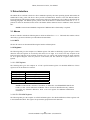
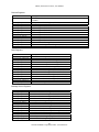
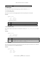
DIO24 24-Bit Discrete Digital I/O PCI-DIO24 PCI-DIO24-GD1 Linux Device Driver User Manual Manual Revision: January 25, 2005 General Standards Corporation 8302A Whitesburg Drive Huntsville, AL 35802 Phone: (256) 880-8787 Fax: (256) 880-8788 URL: http://www.generalstandards.com E-mail: [email protected] E-mail: [email protected] DIO24, Linux Device Driver, User Manual 2 General Standards Corporation, Phone: (256) 880-8787 DIO24, Linux Device Driver, User Manual Preface Copyright ©2005, General Standards Corporation Additional copies of this manual or other literature may be obtained from: General Standards Corporation 8302A Whitesburg Dr. Huntsville, Alabama 35802 Phone: (256) 880-8787 FAX: (256) 880-8788 URL: http://www.generalstandards.com E-mail: [email protected] General Standards Corporation makes no warranty of any kind with regard to this material, including, but not limited to, the implied warranties of merchantability and fitness for a particular purpose. Although extensive editing and reviews are performed before release to ECO control, General Standards Corporation assumes no responsibility for any errors that may exist in this document. No commitment is made to update or keep current the information contained in this document. General Standards Corporation does not assume any liability arising out of the application or use of any product or circuit described herein, nor is any license conveyed under any patent rights or any rights of others. General Standards Corporation assumes no responsibility for any consequences resulting from omissions or errors in this manual or from the use of information contained herein. General Standards Corporation reserves the right to make any changes, without notice, to this product to improve reliability, performance, function, or design. ALL RIGHTS RESERVED. The Purchaser of this software may use or modify in source form the subject software, but not to re-market or distribute it to outside agencies or separate internal company divisions. The software, however, may be embedded in the Purchaser’s distributed software. In the event the Purchaser’s customers require the software source code, then they would have to purchase their own copy of the software. General Standards Corporation makes no warranty of any kind with regard to this software, including, but not limited to, the implied warranties of merchantability and fitness for a particular purpose and makes this software available solely on an “as-is” basis. General Standards Corporation reserves the right to make changes in this software without reservation and without notification to its users. The information in this document is subject to change without notice. This document may be copied or reproduced provided it is in support of products from General Standards Corporation. For any other use, no part of this document may be copied or reproduced in any form or by any means without prior written consent of General Standards Corporation. GSC is a trademark of General Standards Corporation. PLX and PLX Technology are trademarks of PLX Technology, Inc. 3 General Standards Corporation, Phone: (256) 880-8787 DIO24, Linux Device Driver, User Manual Table of Contents 1. Introduction............................................................................................................................... 6 1.1. Purpose ..............................................................................................................................................................6 1.2. Acronyms...........................................................................................................................................................6 1.3. Definitions..........................................................................................................................................................6 1.4. Software Overview............................................................................................................................................6 1.5. Hardware Overview..........................................................................................................................................6 1.6. Reference Material............................................................................................................................................6 2. Installation ................................................................................................................................. 8 2.1. CPU and Kernel Support .................................................................................................................................8 2.2. The /proc File System .......................................................................................................................................8 2.3. File List ..............................................................................................................................................................8 2.4. Installation.........................................................................................................................................................8 2.5. Removal .............................................................................................................................................................9 2.6. The Driver .........................................................................................................................................................9 2.6.1. Build .............................................................................................................................................................9 2.6.2. Startup ........................................................................................................................................................10 2.6.3. Verification.................................................................................................................................................11 2.6.4. Version .......................................................................................................................................................11 2.6.5. Shutdown....................................................................................................................................................11 2.7. Document Source Code Examples.................................................................................................................12 2.7.1. Build ...........................................................................................................................................................12 2.7.2. Use..............................................................................................................................................................12 2.8. Sample Application.........................................................................................................................................13 2.8.1. dio24Test.o .................................................................................................................................................13 2.8.2. Build ...........................................................................................................................................................13 2.8.3. Execute .......................................................................................................................................................13 3. Driver Interface....................................................................................................................... 15 3.1. Macros..............................................................................................................................................................15 3.1.1. IOCTL ........................................................................................................................................................15 3.1.2. Registers .....................................................................................................................................................15 3.2. Data Types .......................................................................................................................................................18 3.2.1. dio24_debug_data_t ...................................................................................................................................18 3.2.2. dio24_driver_info_t....................................................................................................................................18 3.2.3. dio24_reg_t.................................................................................................................................................18 3.3. Functions..........................................................................................................................................................19 3.3.1. close() .........................................................................................................................................................19 3.3.2. ioctl() ..........................................................................................................................................................20 3.3.3. open()..........................................................................................................................................................20 3.3.4. read() ..........................................................................................................................................................21 3.3.5. write() .........................................................................................................................................................21 3.4. IOCTL Services...............................................................................................................................................21 4 General Standards Corporation, Phone: (256) 880-8787 DIO24, Linux Device Driver, User Manual 3.4.1. DIO24_IOCTL_DEBUG_DATA_GET.....................................................................................................22 3.4.2. DIO24_IOCTL_DRIVER_INFO_GET .....................................................................................................22 3.4.3. DIO24_IOCTL_NO_COMMAND ............................................................................................................23 3.4.4. DIO24_IOCTL_REG_MOD ......................................................................................................................24 3.4.5. DIO24_IOCTL_REG_READ ....................................................................................................................24 3.4.6. DIO24_IOCTL_REG_WRITE...................................................................................................................25 Document History ....................................................................................................................... 27 5 General Standards Corporation, Phone: (256) 880-8787 DIO24, Linux Device Driver, User Manual 1. Introduction This user manual applies to driver version 1.06, release 0. 1.1. Purpose The purpose of this document is to describe the interface to the DIO24 Linux device driver. This software provides the interface between "Application Software" and the DIO24 board. The interface to this board is at the device level. 1.2. Acronyms The following is a list of commonly occurring acronyms used throughout this document. Acronyms DMA PCI Description Direct Memory Access Peripheral Component Interconnect 1.3. Definitions The following is a list of commonly occurring terms used throughout this document. Term Driver Application Definition Driver means the kernel mode device driver, which runs in the kernel space with kernel mode privileges. Application means the user mode process, which runs in the user space with user mode privileges. 1.4. Software Overview The DIO24 driver software executes under control of the Linux operating system and runs in Kernel Mode as a Kernel Mode device driver. The DIO24 device driver is implemented as a standard dynamically loadable Linux device driver written in the ‘C’ programming language. With the driver, user applications are able to open and close a device and, while open, perform I/O control operations. 1.5. Hardware Overview The DIO24 is a simple 25-bit discrete I/O interface board. The host side connection is PCI based and the external I/O interface is via a 50 pin connector. The external interface includes 24 pin pairs that can be arbitrarily programmed as either input or output and one pin pair that is input only. The 24 programmable pins are divided into three groups of eight pins each; Port A, Port B and Port C. Ports A and B are each programmable as all inputs or all outputs. The Port C pins are individually programmable. The DIO24 has no DMA or interrupt functionality. 1.6. Reference Material The following reference material may be of particular benefit in using the DIO24 and this driver. The specifications provide the information necessary for an in depth understanding of the specialized features implemented on this board. • The applicable DIO24 User Manual from General Standards Corporation. • The PCI9080 PCI Bus Master Interface Chip data handbook from PLX Technology, Inc. PLX Technology Inc. 870 Maude Avenue 6 General Standards Corporation, Phone: (256) 880-8787 DIO24, Linux Device Driver, User Manual Sunnyvale, California 94085 USA Phone: 1-800-759-3735 WEB: http://www.plxtech.com 7 General Standards Corporation, Phone: (256) 880-8787 DIO24, Linux Device Driver, User Manual 2. Installation 2.1. CPU and Kernel Support The driver is designed to operate with Linux kernel versions 2.2, 2.4 and 2.6 running on a PC system with one or more Intel x86 processors. Testing was performed under kernel versions 2.2.14-5 (Red Hat Linux 6.2), 2.4.20-8 (Red Hat Linux 9) and 2.6.9-1.667 (Red Hat Fedora Core 3). Testing was performed on a standard desktop PC system with a single Intel x86 processor. NOTE: The driver may have to be rebuilt before being used due to kernel version differences between the GSC build host and the customer’s target host. NOTE: The driver has not been tested with a non-versioned kernel. NOTE: The driver has not been tested on an SMP host. 2.2. The /proc File System While the driver is installed, the text file /proc/dio24 can be read to obtain information about the driver. Each file entry includes an entry name followed immediately by a colon, a space character, then the entry value. Below is an example of what appears in the file, followed by descriptions of each entry. version: 1.06 built: Jan 25 2005, 16:29:55 boards: 1 Entry version built boards Description This gives the driver version number in the form x.xx. This gives the driver build date and time in the C form of printf("%s, %s", __DATE__, __TIME__). This identifies the total number of boards the driver detected. 2.3. File List This release consists of the below listed files. The archives are described in detail in following subsections. File dio24.tar.gz dio24_linux_driver_user_manual.pdf Description This archive contains the driver and all related sources. This is a PDF version of this user manual. 2.4. Installation Install the driver and its related files following the below listed steps. This includes the device driver, the documentation source code, and the sample application. 1. Change the current directory to /usr/src/linux/drivers. (The path name may vary among distributions and kernel versions.) 2. Copy the archive file dio24.tar.gz into the current directory. 3. Issue the following command to decompress and extract the files from the provided archive. This creates the directory dio24 in the current directory, and then copies all of the archive’s files into this new directory. 8 General Standards Corporation, Phone: (256) 880-8787 DIO24, Linux Device Driver, User Manual tar –xzvf dio24.tar.gz 2.5. Removal Follow the below steps to remove the driver and its related files. This includes the device driver, the documentation source code, and the sample application. 1. Shutdown the driver as described in following paragraphs. 2. Change to the directory where the driver archive was installed. This should be /usr/src/linux/drivers. (The path name may vary among distributions and kernel versions.) 3. Issue the below command to remove the driver archive and all of the installed driver files. rm –rf dio24.tar.gz dio24 4. Issue the below command to remove all of the installed device nodes. rm –rf /dev/dio24* 5. If the automated startup procedure was adopted (described in following paragraphs), then edit the system startup script rc.local and remove the line that invokes the dio24_start script. The file rc.local should be located in the /etc/rc.d directory. 2.6. The Driver This driver and its related files are contained in the archive file dio24.tar.gz. The archive’s device driver files are listed below. The paragraphs that follow give installation, build and startup instructions. File *.c *.h dio24.h dio24.ko * dio24_start makefile makefile.dep Description The driver source files. The driver header files. A driver header file. This header should be included by DIO24 applications. The driver executable. Shell script to install the driver executable and device nodes. The driver make file. An automatically generated make dependency file. * The file name extension for the pre-built driver executable is .ko, which is the convention for the 2.6 kernel. The 2.6 build of the driver executable is included in the release as the final release is built using the 2.6 kernel. The convention for the 2.2 and 2.4 kernels is an extension of .o. The driver build procedure produces the appropriately named file. 2.6.1. Build NOTE: Building the driver requires installation of the kernel sources. Follow the below steps to build the driver. 1. Change to the directory where the driver and its sources were installed. This should be /usr/src/linux/drivers/dio24/driver. 2. Remove all existing build targets by issuing the below command. 9 General Standards Corporation, Phone: (256) 880-8787 DIO24, Linux Device Driver, User Manual make –f makefile clean 3. Build the driver by issuing the below command. make –f makefile all NOTE: Due to the differences between the many Linux distributions some build errors may occur. These errors may include system header location differences and should be easily correctable. 2.6.2. Startup The startup script used in this procedure is designed to insure that the driver module in the install directory is the module that is loaded. This is accomplished by making sure that an already loaded module is first unloaded before attempting to load the module from the disk drive. In addition, the script also deletes and recreates the device nodes. This is done to insure that the device nodes in use have the same major number as assigned dynamically to the driver by the kernel, and so that the number of device nodes correspond to the number of boards identified by the driver. NOTE: The driver may have to be rebuilt before being used due to kernel version differences between the GSC build host and the customer target host. 2.6.2.1. Manual Driver Startup Procedures Start the driver manually by following the below listed steps. 1. Login as root user, as some of the steps require root privileges. 2. Change to the directory where the driver /usr/src/linux/drivers/dio24/driver. 3. Install the driver module and create the device nodes by executing the below command. If any errors are encountered then an appropriate error message will be displayed. was installed. This should be ./dio24_start NOTE: The script’s default specifies that the driver is installed in the same directory as the script. The script will fail if this is not so. NOTE: The above step must be repeated each time the host is rebooted. NOTE: The DIO24 device node major number is assigned dynamically by the kernel. The minor numbers and the device node suffix numbers are index numbers beginning with zero, and increase by one for each additional board installed. 4. Verify that the device module has been loaded by issuing the below command and examining the output. The module name dio24 should be included in the output. lsmod 5. Verify that the device nodes have been created by issuing the below command and examining the output. The output should include one node for each installed board. ls –l /dev/dio24* 10 General Standards Corporation, Phone: (256) 880-8787 DIO24, Linux Device Driver, User Manual 2.6.2.2. Automatic Driver Startup Procedures Start the driver automatically with each system reboot by following the below listed steps. 1. Locate and edit the system startup script rc.local, which should be in the /etc/rc.d directory. Modify the file by adding the below line so that it is executed with every reboot. /usr/src/linux/drivers/dio24/driver/dio24_start NOTE: The script’s default specifies that the driver is installed in the same directory as the script. The startup script will fail if this is not so. 2. Load the driver and create the required device nodes by rebooting the system. 3. Verify that the driver is loaded and that the device nodes have been created by following the verification steps given in the manual startup procedures. 2.6.3. Verification WARNING: When using the test application the DIO24 and any externally attached equipment may be damaged if the DIO24’s external interface has a cable other than an appropriate loop back cable attached. Damage may result because the test application methodically configures each I/O pin as an input then an output, and alternately drives the output to both its high and low states. No damage will result if no cable at all is attached. NOTE: Refer to the board user manual for information on the loop back test cable. Follow the below steps to verify that the driver has been properly installed and started. 1. Install the sample applications as described in subsequent paragraphs. 2. Change to the directory where the test application dio24Test.o was installed. 3. Start the test application by issuing the below command. ./dio24Test.o NOTE: As described elsewhere, the test application fill not successfully test a DIO24 if an appropriate loop back cable is not attached to the external interface. The cable requirements are described elsewhere as well. If a cable is unattached the application will still test the driver and the DIO24’s PCI interface. 2.6.4. Version The driver version number can be obtained in a variety of ways. It is reported by the driver both when the driver is loaded and when it is unloaded (depending on kernel configuration options, this may be visible only in /var/log/messages). It is recorded in the text file /proc/dio24. It can also be read by an application via the DIO24_IOCTL_DRIVER_INFO_GET IOCTL services. 2.6.5. Shutdown Shutdown the driver following the below listed steps. 1. Login as root user, as some of the steps require root privileges. 11 General Standards Corporation, Phone: (256) 880-8787 DIO24, Linux Device Driver, User Manual 2. If the driver is currently loaded then issue the below command to unload the driver. rmmod dio24 3. Verify that the driver module has been unloaded by issuing the below command. The module name dio24 should not be in the list. lsmod 2.7. Document Source Code Examples The archive file dio24.tar.gz contains all of the source code examples included in this document. In addition, they are included as a statically linkable library usable with DIO24 console applications. The library and sources are delivered undocumented and unsupported. The purpose of these files is to verify that the documentation samples compile and to provide a library of working sample code to assist in a user’s learning curve and application development effort. The archive content is not described here, though its use is described in the following paragraphs. These files are installed into the directory /usr/src/linux/drivers/dio24/docsrc. File *.c DIO24DocSrcLib.a DIO24DocSrcLib.h makefile makeile.dep Description These are the C source files. This is a pre-built, linkable version of the library. This is the library header file. This is the library make file. This is an automatically generated make dependency file. 2.7.1. Build Follow the below steps to compile the example files. 1. Change to the directory where the source code example files were installed. This should be /usr/src/linux/drivers/dio24/docsrc. 2. Remove all existing build targets by issuing the below command. make –f makefile clean 3. Compile the sample files by issuing the below command. make –f makefile all NOTE: The build procedure will fail if the driver sources are not installed in the directory documented in the driver installation procedures. 2.7.2. Use The library is used both at application compile time and at application link time. Compile time use has two requirements. First, include the header file DIO24DocSrcLib.h in each module referencing a library component. Second, expand the include file search path to search the directory where the library header is located. This should be /usr/src/linux/drivers/dio24/docsrc. Link time use also has two requires. First, include the static library DIO24DocSrcLib.a in the list of files to be linked into the application. Second, expand the library file search path to search the directory where the library is located. This should also be /usr/src/linux/drivers/dio24/docsrc. 12 General Standards Corporation, Phone: (256) 880-8787 DIO24, Linux Device Driver, User Manual 2.8. Sample Application 2.8.1. dio24Test.o CAUTION: When using the sample application the DIO24 and any externally attached equipment may be damaged if the DIO24’s external interface has a cable attached. Damage may result because the sample application uses a configuration which drives various external output signals. No damage will result if no cable at all is attached. This sample application provides a command line driven Linux application that tests the functionality of the driver and a user specified DIO24 board. It can be used as the starting point for application development on top of the DIO24 Linux device driver. It utilizes the library DIO24DocSrcLib and is delivered undocumented and unsupported. It can however be used as a starting point for developing applications on top of the Linux driver and to help ease the learning curve. The application performs an automated test of the driver features. The application includes the below listed files, installed into the directory /usr/src/linux/drivers/dio24/test. NOTE: For the test application to successfully verify the functionality of a DIO24, an appropriate loop back cable must be attached to the external interface. Refer to the board user manual for information on the loop back test cable. File dio24Test.c dio24Test.o makefile makeile.dep makeapp.sh Description This is the source file. This is the pre-built test application. This is the application make file. This is an automatically generated make dependency file. This is the build script for the sample application. 2.8.2. Build Follow the below steps to build/rebuild the sample application. 1. Change to the directory where the sample application was installed. This should be /usr/src/linux/drivers/dio24/test. 2. Remove all existing build targets by issuing the below command. make –f makefile clean 3. Build the application by issuing the below command. make –f makefile all 2.8.3. Execute WARNING: When using the test application the DIO24 and any externally attached equipment may be damaged if the DIO24’s external interface has a cable other than an appropriate loop back cable attached. Damage may result because the test application methodically configures each I/O pin as an input then an output, and alternately drives the output to both its high and low states. No damage will result if no cable at all is attached. NOTE: If an appropriate loop back cable is not attached, then the application will fail as soon as the procedure begins testing the DIO24’s I/O capabilities. In this case, the application still verifies the operation of the driver and the board’s PCI interface. 13 General Standards Corporation, Phone: (256) 880-8787 DIO24, Linux Device Driver, User Manual NOTE: Refer to the board user manual for information on the loop back test cable. Follow the below steps to execute and exercise the test application. 1. Change to the directory where the sample application was installed. 2. Start the sample application by issuing the command given below. The application uses the command line arguments given to direct its course of action. Once started the application will automatically execute a series of tests to verify the operation of the driver and the board. A single test cycle should take less than one second to complete. The “index” argument specifies the index of the board to access and is required only if multiple boards are installed. The first board is index zero (0). The argument “-c” specifies to run the test continuously until an error is encountered. The argument “-C” specifies to run the test continuously even if errors are encountered. The argument –n#, where # is a integer number, is the maximum number of tests to run when continuous testing is being performed. The argument –m#, where # is a integer number, is the maximum number of minutes to run tests when continuous testing is being performed. At the end of each test cycle the application reports accumulative test results. ./dio24Test.o <-c> <-C> <-n#> <-m#> <index> 14 General Standards Corporation, Phone: (256) 880-8787 DIO24, Linux Device Driver, User Manual 3. Driver Interface The DIO24 driver conforms to the device driver standards required by the Linux Operating System and contains the standard driver entry points. The device driver provides a standard driver interface to the GSC DIO24 board for Linux applications. The interface includes various macros, data types and functions, all of which are described in the following paragraphs. The DIO24 specific portion of the driver interface is defined in the header file dio24.h, portions of which are described in this section. The header defines numerous items in addition to those described here. NOTE: Contact General Standards Corporation if additional driver functionality is required. 3.1. Macros The driver interface includes the following macros which are defined in dio24.h. The header also contains various other utility type macros which are provided without documentation. 3.1.1. IOCTL The IOCTL macros are documented following the function call descriptions. 3.1.2. Registers The following table gives the complete set of DIO24 registers. The tables are divided by register categories. Unless otherwise stated, all registers are accessed by their native size of eight, 16 or 32-bits. The only exception is the PCICCR register which is 24 bits wide but accessed as if it were 32-bits wide. In this instance the upper eight-bits are to be ignored. Register values are passed as 32-bit entities, but bits outside the a register’s native size are ignored. 3.1.2.1. GSC Registers The following table gives the complete set of GSC specific DIO24 registers. For detailed definitions of these registers refer to the DIO24 User Manual. Macros DIO24_GSC_BCR DIO24_GSC_BSR DIO24_GSC_DDIR DIO24_GSC_DDOR DIO24_GSC_FRR DIO24_GSC_IOCR Description Board Control Register (BCR) Board Status Register (BSR) Discrete Data Input Register (DDIR) Discrete Data Output Register (DDOR) Firmware Revision Register (FRR) I/O Control Register (IOCR) NOTE: For DIO24-GD1 variations of the DIO24, an FRR value of 0xXX0BXXXX identifies the board as a GD1 version rather than an HPDI32. This is relevant for identification only, and does not reflect any functional differences. Refer to the PCI registers for additional identification information. 3.1.2.2. PLX PCI 9080 Registers The following table gives the complete set of PLX PCI9080 registers. For detailed definitions of these registers refer to the PCI9080 Data Book. The registers are presented as grouped in the PLX data book. 15 General Standards Corporation, Phone: (256) 880-8787 DIO24, Linux Device Driver, User Manual PCI Configuration Registers Macros DIO24_PCI_BAR0 DIO24_PCI_BAR1 DIO24_PCI_BAR2 DIO24_PCI_BAR3 DIO24_PCI_BAR4 DIO24_PCI_BAR5 DIO24_PCI_BISTR DIO24_PCI_CCR DIO24_PCI_CIS DIO24_PCI_CLSR DIO24_PCI_CR DIO24_PCI_ERBAR DIO24_PCI_HTR DIO24_PCI_IDR DIO24_PCI_ILR DIO24_PCI_IPR DIO24_PCI_LTR DIO24_PCI_MGR DIO24_PCI_MLR DIO24_PCI_REV DIO24_PCI_SID DIO24_PCI_SR DIO24_PCI_SVID Description PCI Base Address Register for Memory Accesses to Local, Runtime, and DMA Registers (PCIBAR0) PCI Base Address Register for I/O Accesses to Local, Runtime, and DMA Registers (PCIBAR1) PCI Base Address Register for Memory Accesses to Local Address Space 0 (PCIBAR2) PCI Base Address Register for Memory Accesses to Local Address Space 1 (PCIBAR3) Unused Base Address (PCIBAR4) Unused Base Address (PCIBAR5) PCI Built-In Self Test Register (PCIBISTR) PCI Class Code Register (PCICCR) PCI Cardbus CIS Pointer Register (PCICIS) PCI Cache Line Size Register (PCICLSR) PCI Command Register (PCICR) PCI Expansion ROM Base Address (PCIERBAR) PCI Header Type Register (PCIHTR) PCI Configuration ID Register (PCIIDR) PCI Interrupt Line Register (PCIILR) PCI Interrupt Pin Register (PCIIPR) PCI Latency Timer Register (PCILTR) PCI Min_Gnt Register (PCIMGR) PCI Max_Lat Register (PCIMLR) PCI Revision ID Register (PCIREV) PCI Subsystem ID Register (PCISID) PCI Status Register (PCISR) PCI Subsystem Vendor ID Register (PCISVID) NOTE: A PCIIDR value of 0x908010B5 identifies the PCI interface chip as a PLX PCI9080. A PCISVID value of 0x10B5 indicates that the PCISID value has been assigned by PLX. A PCISID value of 0x2706 identifies the board as a DIO24. A PCISID value of 0x2400 identifies that the DIO24 is a GD1 variation, which falls under the HPDI32 product line. Refer to the GSC Firmware Revision Register for additional identification information. This is relevant for identification only, and does not reflect any functional differences. Local Configuration Registers Macros DIO24_PLX_BIGEND DIO24_PLX_DMCFGA DIO24_PLX_DMLBAI DIO24_PLX_DMLBAM DIO24_PLX_DMPBAM DIO24_PLX_DMRR DIO24_PLX_EROMBA DIO24_PLX_EROMRR DIO24_PLX_LAS0BA DIO24_PLX_LAS0RR DIO24_PLX_LAS1BA DIO24_PLX_LAS1RR DIO24_PLX_LBRD0 DIO24_PLX_LBRD1 DIO24_PLX_MARBR Description Big/Little Endian Descriptor Register (BIGEND) PCI Configuration Address Register for Direct Master to PCI IO/CFG (DMCFGA) Local Bus Base Address Register for Direct Master to PCI IO/CFG (DMLBAI) Local Bus Base Address Register for Direct Master to PCI Memory (DMLBAM) PCI Base Address Register for Direct Master to PCI Memory (DMPBAM) Local Range Register for Direct Master to PCI (DMRR) Expansion ROM Local Base Address Register (EROMBA) Expansion ROM Range Register (EROMRR) Local Address Space 0 Local Base Address Register (LASOBA) Local Address Space 0 Range Register for PCI-to-Local Bus (LASORR) Local Address Space 1 Local Base Address Register (LAS1BA) Local Address Space 1 Range Register for PCI-to-Local Bus (LAS1RR) Local Address Space 0/Expansion ROM Bus Region Descriptor Register (LBRD0) Local Address Space 1 Bus Region Descriptor Register (LBRD1) Mode Arbitration Register (MARBR) 16 General Standards Corporation, Phone: (256) 880-8787 DIO24, Linux Device Driver, User Manual Runtime Registers Macros DIO24_PLX_CNTRL DIO24_PLX_INTCSR DIO24_PLX_L2PDBELL DIO24_PLX_MBOX0 DIO24_PLX_MBOX1 DIO24_PLX_MBOX2 DIO24_PLX_MBOX3 DIO24_PLX_MBOX4 DIO24_PLX_MBOX5 DIO24_PLX_MBOX6 DIO24_PLX_MBOX7 DIO24_PLX_P2LDBELL DIO24_PLX_PCIHIDR DIO24_PLX_PCIHREV Description Serial EEPROM Control, CPI Command Codes, User I/O, Init Control Register (CNTRL) Interrupt Control/Status Register (INTCSR) Local-to-PCI Doorbell Register (L2PDBELL) Mailbox Register 0 (MBOX0) Mailbox Register 1 (MBOX1) Mailbox Register 2 (MBOX2) Mailbox Register 3 (MBOX3) Mailbox Register 4 (MBOX4) Mailbox Register 5 (MBOX5) Mailbox Register 6 (MBOX6) Mailbox Register 7 (MBOX7) PCI-to-Local Doorbell Register (P2LDBELL) PCI Permanent Configuration ID Register (PCIHIDR) PCI Permanent Revision ID Register (PCIHREV) DMA Registers Macros DIO24_PLX_DMAARB DIO24_PLX_DMACSR0 DIO24_PLX_DMACSR1 DIO24_PLX_DMADPR0 DIO24_PLX_DMADPR1 DIO24_PLX_DMALADR0 DIO24_PLX_DMALADR1 DIO24_PLX_DMAMODE0 DIO24_PLX_DMAMODE1 DIO24_PLX_DMAPADR0 DIO24_PLX_DMAPADR1 DIO24_PLX_DMASIZ0 DIO24_PLX_DMASIZ1 DIO24_PLX_DMATHR Description DMA Arbitration Register (DMAARB) DMA Channel 0 Command/Status Register (DMACSR0) DMA Channel 1 Command/Status Register (DMACSR1) DMA Channel 0 Descriptor Pointer Register (DMADPR0) DMA Channel 1 Descriptor Pointer Register (DMADPR1) DMA Channel 0 Local Address Register (DMALADR0) DMA Channel 1 Local Address Register (DMALADR1) DMA Channel 0 Mode Register (DMAMODE0) DMA Channel 1 Mode Register (DMAMODE1) DMA Channel 0 PCI Address Register (DMAPADR0) DMA Channel 1 PCI Address Register (DMAPADR1) DMA Channel 0 Transfer Size Register (DMASIZ0) DMA Channel 1 Transfer Size Register (DMASIZ1) DMA Threshold Register (DMATHR) Message Queue Registers Macros DIO24_PLX_IFHPR DIO24_PLX_IFTPR DIO24_PLX_IPHPR DIO24_PLX_IPTPR DIO24_PLX_IQP DIO24_PLX_MQCR DIO24_PLX_OFHPR DIO24_PLX_OFTPR DIO24_PLX_OPHPR DIO24_PLX_OPLFIM DIO24_PLX_OPLFIS DIO24_PLX_OPTPR DIO24_PLX_OQP DIO24_PLX_QBAR Description Inbound Free Head Pointer Register (IFHPR) Inbound Free Tail Pointer Register (IFTPR) Inbound Post Head Pointer Register (IPHPR) Inbound Post Tail Pointer Register (IPTPR) Inbound Queue Port Register (IQP) Messaging Queue Configuration Register (MQCR) Outbound Free Head Pointer Register (OFHPR) Outbound Free Tail Pointer Register (OFTPR) Outbound Post Head Pointer Register (OPHPR) Outbound Post List FIFO Interrupt Mask Register (OPLFIM) Outbound Post List FIFO Interrupt Status Register (OPLFIS) Outbound Post Tail Pointer Register (OPTPR) Outbound Queue Port Register (OQP) Queue Base Address Register (QBAR) 17 General Standards Corporation, Phone: (256) 880-8787 DIO24, Linux Device Driver, User Manual DIO24_PLX_QSR Queue Status/Control Register (QSR) 3.2. Data Types This driver interface includes the following data types which are defined in dio24.h. 3.2.1. dio24_debug_data_t This structure is used for driver debugging purposes and is used only during driver development. Definition typedef struct { __u32 valid; __s8 msg[128]; __u32 ul[16]; } dio24_debug_data_t; Fields valid msg ul Description If this field is non-zero then the recorded data is valid. The data is otherwise meaningless. This is a textual message relating to some operation being debugged. This is a set of values related to the above message. 3.2.2. dio24_driver_info_t This structure defines the data fields for the information returned by the DIO24_DRIVER_INFO_GET IOCTL service. Definition typedef struct { __s8 version[8]; __s8 built[32]; } dio24_driver_info_t; Fields version built Description This field gives the driver version number as a string in the form of X.XX. This field gives the driver build date and time as a string. It is given in the C form of printf("%s, %s", __DATE__, __TIME__). 3.2.3. dio24_reg_t This structure defines the data fields for the information involved in the register access IOCTL services. Read the details of the individual services for additional information. Definition typedef struct { __u32 reg; __u32 value; __u32 mask; 18 General Standards Corporation, Phone: (256) 880-8787 DIO24, Linux Device Driver, User Manual } dio24_reg_t; Fields reg value mask Description This field identifies the register to be accessed. This field identifies the value retrieved by read operations and the value to apply by write operations. This field identifies the register bits from the value field that are to be applied during the readmodify-write IOCTL service. If a bit is set in the mask, then the corresponding value bit is applied to the register. If a mask bit is not set then the corresponding register bit is left unchanged. 3.3. Functions This driver interface includes the following functions. 3.3.1. close() This function is the entry point to close a connection to an open DIO24 board. This function should only be called after a successful open of the respective device. Prototype int close(int fd); Argument fd Description This is the file descriptor of the device to be closed. Return Value -1 0 Description An error occurred. Consult errno. The operation succeeded. Example /* This software is covered by the GNU GENERAL PUBLIC LICENSE (GPL). */ #include <errno.h> #include <stdio.h> #include <unistd.h> #include "DIO24DocSrcLib.h" int dio24_close(int fd, int verbose) { int status; status = close(fd); if ((verbose) && (status == -1)) printf("close() failure, errno = %d\n", errno); } return(status); 19 General Standards Corporation, Phone: (256) 880-8787 DIO24, Linux Device Driver, User Manual 3.3.2. ioctl() This function is the entry point to performing setup and control operations on a DIO24 board. This function should only be called after a successful open of the respective device. The specific operation performed varies according to the request argument. The request argument also governs the use and interpretation of any additional arguments. The set of supported IOCTL services is defined in a following section. Prototype int ioctl(int fd, int request, ...); Argument fd request ... Description This is the file descriptor of the device to access. This specifies the desired operation to be performed. This is any additional arguments. If request does not call for any additional arguments, then any additional arguments provided are ignored. The DIO24 IOCTL services use at most one argument, which is represented by a 32-bit value. Return Value -1 0 Description An error occurred. Consult errno. The operation succeeded. Example /* This software is covered by the GNU GENERAL PUBLIC LICENSE (GPL). */ #include <errno.h> #include <stdio.h> #include <sys/ioctl.h> #include "DIO24DocSrcLib.h" int dio24_ioctl(int fd, int request, void *arg, int verbose) { int status; status = ioctl(fd, request, (unsigned long) arg); if ((verbose) && (status == -1)) printf("ioctl() failure, errno = %d\n", errno); } return(status); 3.3.3. open() This function is the entry point to open a connection to a DIO24 board. Prototype int open(const char* pathname, int flags); Argument pathname flags Description This is the name of the device to open. This is the desired read/write access. Use O_RDWR. 20 General Standards Corporation, Phone: (256) 880-8787 DIO24, Linux Device Driver, User Manual NOTE: Another form of the open() function has a mode argument. This form is not displayed here as the mode argument is ignored when opening an existing file/device. Return Value -1 else Description An error occurred. Consult errno. A valid file descriptor. Example /* This software is covered by the GNU GENERAL PUBLIC LICENSE (GPL). */ #include <assert.h> #include <errno.h> #include <fcntl.h> #include <stdio.h> #include "DIO24DocSrcLib.h" int dio24_open(int board, int verbose) { int fd; char name[80]; assert(board >= 0); sprintf(name, "/dev/dio24%d", board); fd = open(name, O_RDWR); if ((verbose) && (fd == -1)) { printf( "open() failure on %s, errno = %d\n", name, errno); } } return(fd); 3.3.4. read() The DIO24 does not support a read operation as the board has neither data storage nor synchronous data reception capability. Data read operations are performed by reading the appropriate register. 3.3.5. write() The DIO24 does not support a write operation as the board has neither data storage nor synchronous data transmission capability. Data write operations are performed by writing to the appropriate register. 3.4. IOCTL Services The DIO24 driver implements the following IOCTL services. Each service is described along with the applicable ioctl() function arguments. In the definitions given the optional argument is identified as arg and is an unsigned long data type. Unless otherwise stated the return value definitions are those defined for the ioctl() function call and any errors codes are accessed via errno. 21 General Standards Corporation, Phone: (256) 880-8787 DIO24, Linux Device Driver, User Manual 3.4.1. DIO24_IOCTL_DEBUG_DATA_GET This service retrieves debug data produced by temporary code included in the driver only during driver debugging and development. Usage ioctl() Argument request arg Description DIO24_IOCTL_DEBUG_DATA_GET dio24_debug_data_t* Example /* This software is covered by the GNU GENERAL PUBLIC LICENSE (GPL). */ #include <errno.h> #include <stdio.h> #include <sys/ioctl.h> #include "DIO24DocSrcLib.h" int dio24_debug_read(int fd, int verbose) { dio24_debug_data_t debug; int i; int j; int status; status = ioctl(fd, DIO24_IOCTL_DEBUG_DATA_GET, &debug); if (verbose == 0) { } else if (status == -1) { printf("ioctl() failure, errno = %d\n", errno); } else if (debug.valid) { printf("Debug Data:\n"); printf(" msg: '%s'\n", debug.msg); i = sizeof(debug.ul) / sizeof(debug.ul[0]); } } for (j = 0; j < i; j++) { printf( " ul[%2d]: 0x%08lX\n", j, (unsigned long) debug.ul[j]); } return(status); 3.4.2. DIO24_IOCTL_DRIVER_INFO_GET This service retrieves information about the driver itself. 22 General Standards Corporation, Phone: (256) 880-8787 DIO24, Linux Device Driver, User Manual Usage ioctl() Argument request arg Description DIO24_IOCTL_DRIVER_INFO_GET dio24_driver_info_t* Example /* This software is covered by the GNU GENERAL PUBLIC LICENSE (GPL). */ #include <errno.h> #include <stdio.h> #include <sys/ioctl.h> #include "DIO24DocSrcLib.h" int dio24_driver_info(int fd, dio24_driver_info_t* info, int verbose) { int status; status = ioctl(fd, DIO24_IOCTL_DRIVER_INFO_GET, (unsigned long) info); if ((verbose) && (status == -1)) printf("ioctl() failure, errno = %d\n", errno); } return(status); 3.4.3. DIO24_IOCTL_NO_COMMAND This is an empty driver entry point. This IOCTL may be given to verify that the driver is correctly installed and that a DIO24 has been successfully opened. If an error status is returned then something isn’t working properly. Usage ioctl() Argument request arg Description DIO24_IOCTL_NO_COMMAND Not used. Example /* This software is covered by the GNU GENERAL PUBLIC LICENSE (GPL). */ #include <errno.h> #include <stdio.h> #include <sys/ioctl.h> #include "DIO24DocSrcLib.h" int dio24_no_command(int fd, int verbose) { int status; status = ioctl(fd, DIO24_IOCTL_NO_COMMAND); if ((verbose) && (status == -1)) 23 General Standards Corporation, Phone: (256) 880-8787 DIO24, Linux Device Driver, User Manual printf("ioctl() failure, errno = %d\n", errno); } return(status); 3.4.4. DIO24_IOCTL_REG_MOD This service performs a read-modify-write operation on a DIO24 register. This includes only the GSC specific registers. All PCI and PLX PCI9080 feature set registers are read-only. Refer to dio24.h for a complete list of the accessible registers. Usage ioctl() Argument request arg Description DIO24_IOCTL_REG_MOD dio24_reg_t* Example /* This software is covered by the GNU GENERAL PUBLIC LICENSE (GPL). */ #include <errno.h> #include <stdio.h> #include <sys/ioctl.h> #include "DIO24DocSrcLib.h" int dio24_reg_mod( int fd, unsigned long reg, unsigned long value, unsigned long mask, int verbose) { dio24_reg_t parm; int status; parm.reg parm.value parm.mask status = = = = reg; value; mask; ioctl(fd, DIO24_IOCTL_REG_MOD, (unsigned long) &parm); if ((verbose) && (status == -1)) printf("ioctl() failure, errno = %d\n", errno); } return(status); 3.4.5. DIO24_IOCTL_REG_READ This service reads the value of a DIO24 register. This includes all PCI registers, all PLX PCI9080 feature set registers, and all GSC specific registers. Refer to dio24.h for a complete list of the accessible registers. 24 General Standards Corporation, Phone: (256) 880-8787 DIO24, Linux Device Driver, User Manual Usage ioctl() Argument request arg Description DIO24_IOCTL_REG_READ dio24_reg_t* Example /* This software is covered by the GNU GENERAL PUBLIC LICENSE (GPL). */ #include <errno.h> #include <stdio.h> #include <sys/ioctl.h> #include "DIO24DocSrcLib.h" int dio24_reg_read( int fd, unsigned long reg, unsigned long* value, int verbose) { dio24_reg_t parm; int status; parm.reg parm.value parm.mask status = = = = reg; 0xDEADBEEFL; 0; /* ignored for reads */ ioctl(fd, DIO24_IOCTL_REG_READ, (unsigned long) &parm); if (status == 0) value[0] = parm.value; else if (verbose) printf("ioctl() failure, errno = %d\n", errno); } return(status); 3.4.6. DIO24_IOCTL_REG_WRITE This service writes a value to a DIO24 register. This includes only the GSC specific registers. All PCI and PLX PCI9080 feature set registers are read-only. Refer to dio24.h for a complete list of the accessible registers. Usage ioctl() Argument request arg Description DIO24_IOCTL_REG_WRITE dio24_reg_t* Example /* This software is covered by the GNU GENERAL PUBLIC LICENSE (GPL). */ #include <errno.h> #include <stdio.h> 25 General Standards Corporation, Phone: (256) 880-8787 DIO24, Linux Device Driver, User Manual #include <sys/ioctl.h> #include "DIO24DocSrcLib.h" int dio24_reg_write( int fd, unsigned long reg, unsigned long value, int verbose) { dio24_reg_t parm; int status; parm.reg parm.value parm.mask status = = = = reg; value; 0; /* ignored for writes */ ioctl(fd, DIO24_IOCTL_REG_WRITE, (unsigned long) &parm); if ((verbose) && (status == -1)) printf("ioctl() failure, errno = %d\n", errno); } return(status); 26 General Standards Corporation, Phone: (256) 880-8787 DIO24, Linux Device Driver, User Manual Document History Revision January 25, 2005 January 13, 2005 August 31, 2004 April 26, 2003 July 24, 2002 January 29, 2002 Description Updated to release 1.06.0. Minor editorial changes. Reorganized the directory structure. Ported to the 2.6 kernel. Made the source code samples into a library. Made the driver GPL. Made other minor document mods. Added support for the PCI-DIO24 (no suffix). Ported to the 2.4.7 and 2.4.18 kernels plus other minor updates. Initial release. 27 General Standards Corporation, Phone: (256) 880-8787