1
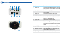
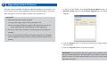
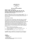
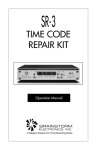
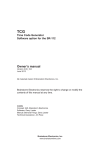
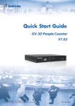
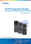
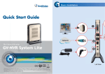
1
Introduction
Welcome to the GV-Box Camera Quick Start Guide. In the following
sections, you will learn about the basic installations and configurations of the
GV-Box camera (GV-BX120D / 220D / 320D). For a detailed user’s manual,
see GV-IPCam H.264 User’s Manual on the GV-IPCam H.264 software CD.
Packing List
• Box Camera
• Terminal Block
• Bag of Six C Mount Lens Adapters
Quick Start Guide
GV-Box Camera
GV-BX120D / 220D / 320D
Thank you for purchasing GV-BX120D / 220D / 320D Camera. This guide is designed to
assist the new user in getting immediate results from the GV-BX120D / 220D / 320D
Camera. For advanced information on how to use the GV-BX120D / 220D / 320D Camera,
please refer to GV-IPCam H.264 User's Manual on Software CD.
© 2010 GeoVision Inc. All rights reserved.
2010/10
English
ICH264V10-BX-QG-A
• Video Out Wire
• DC 12V Power Adapter
• GV-IPCAM H.264 Software CD
2
Overview
1
2
3
4
5
6
No. Name
1
Video Out
Description
Connects to a portable monitor for setting the
focus and angle of Box Camera during initial
installation.
2
Micro SD Card Slot
Inserts a micro SD/SDHC card to store
recording data.
10
9
8
7
3
Audio Out
Connects a speaker for audio output.
4
Audio In
Connects a microphone for audio input.
5
I/O Terminal Block
Connects I/O device. For details, see 2.7 I/O
Terminal Block in the GV-IPCam H.264 User’s
Manual on the software CD.
11
6
Power LED
Indicates the power is supplied.
7
Default
Resets all configurations of the GV-IPCAM
H.264 to the default factory settings. See 8.
Restoring to Default Settings in the Quick Start
Guide.
8
LAN / PoE
Connects to a 10/100 Ethernet or PoE.
9
DC 12V Port
Connects to power.
10
Auto Iris Connector
If the varifocal lens is in use, plug the iris
control cable to the connector.
12
11
Microphone
Records the sounds.
12
Status LED
Turns on when the unit is ready for use.
3
4
Connecting the Camera
The GV-BX120D / 220D / 320D camera is designed for indoor usage. Please
make sure that the installing location is shielded from rain and moisture.
3
3
Optional Installation
A certain distance from the camera’s imaging chip is required to focus the
lens. Mount the supplied C mount adapter to the camera, and then attach the
lens onto the C mount adapter.
The supplied C-mount lens adapters include 3 sizes in thickness:
4
•
0.188 mm (transparent color) x 2
•
0.125 mm (black color with a glossy surface) x 2
•
0.254 mm (black color with a matt surface) x 2
Note: Besides the supplied 6 units of C-mount lens adapters, each
varifocal model has already included with a 0.188 mm C-mount lens
adapter.
6
1
C-mount lens adapter
5
2
1. Plug the iris control cable to the Auto Iris Connector on the camera.
2. Use a standard network cable to connect the camera to your network.
3. Optionally connect a speaker and an external microphone.
4. Optionally connect a monitor using a Video Out wire. If your signal format
is PAL, see the TV Out field in 9.1.1 Video Settings, GV-IPCam H.264
User’s Manual on the software CD.
5. Connect power using one of the following methods:
•
Use the supplied power adapter, connect to power.
•
Use the Power over Ethernet (PoE) function. The power will be
provided over the network cable.
6. The status LED of the camera will be on. Then you can set the IP
address for the unit. See 5. Accessing the Box Camera in the Quick Start
Guide.
5
Accessing the Box Camera
System Requirement
To access the box camera through Web browser, ensure your PC connects
to the network properly and meets this system requirement:
•
Microsoft Internet Explorer 6.x or later
4. Select Static IP address. Type IP Address, Subnet Mask,
Router/Gateway, Primary DNS and Secondary DNS in the Configure
connection parameters section.
5. Click Apply. The camera is now accessible by entering the assigned
IP address on the Web browser.
Note: For the users of Internet Explorer 8, additional settings are
required. For details, see Appendix B in GV-IPCam H.264 User’s
Manual on the software CD.
6. To enable the updating of images in Microsoft Internet Explorer, you
must set your browser to allow ActiveX Controls and perform a
one-time installation of GeoVision’s ActiveX component onto your
computer.
Assigning an IP Address
Designed for use on the network, the GV-Box camera must be assigned an
Important:
IP address to make it accessible:
1. Dynamic IP Address and PPPoE should only be enabled if you
1. Open your web browser, and type the default IP address
http://192.168.0.10.
2. In both Login and Password fields, type the default value admin. Click
Apply.
3. In the left menu, select Network and then LAN to begin the network
settings.
know which IP address the camera will get from the DHCP server or
ISP. Otherwise you must use the Dynamic DNS service to obtain a
domain name linked to the camera’s changing IP address first.
2. If Dynamic IP Address or PPPoE is enabled and you cannot
access the camera, you may have to reset the camera to its factory
default and then perform the network settings again. To restore
factory settings, see 8. Restoring to Default Settings in the Quick
Start Guide.
Continued on the reverse
6
The Web Interface
No. Name
9
Function
1
Play
Plays live video.
2
Stop
Stops playing video.
3
Microphone
Talks to the surveillance area from the local
10
computer.
4
Speaker
Listens to the audio around the camera.
5
Snapshot
Takes a snapshot of live video.
6
File Save
Records live video to the local computer.
7
Full Screen
Switches to full screen view. Right-click the
image to see additional options.
8
Control Panel
Displays the camera information, video
settings, audio data rate, I/O device status,
images captured upon alarm, and GPS location
of the camera. Also allows you to adjust image
1
2
3
4
5
6
7
quality and install the program from the hard
8
drive.
9
Show System Menu
Brings up these functions: Alarm Notify, Video
and Audio Configuration, Remote Config, Show
Camera Name and Image Enhance.
10
I/O Control
Enables the I/O Control Panel and Visual
Automation.
7
Upgrading System Firmware
GeoVision will periodically release the updated firmware on the website. The
1. In the Live View window, click the Show System Menu button, select
new firmware can be simply loaded into the GV-IPCAM H.264 by using the
Remote Config, and click the Firmware Upgrade tab. This dialog box
Web interface or IP Device Utility included in the Software CD.
appears.
Important:
1. While the firmware is being updated,
A) the power supply must not be interrupted, and
B) do not unplug the Ethernet cable if the cable is the source of
power supply (Power over Ethernet or PoE supported).
2. Do not turn the power off within 10 minutes after the firmware is
updated.
3. If you use the IP Device Utility for firmware upgrade, the computer
used to upgrade firmware must be under the same network of the
camera.
2. Click the Browse button to locate the firmware file (.img) saved at your
local computer.
3. Click the Upgrade button to start the upgrade.
WARNING: The interruption of power supply during updating causes
not only update failures but also damages to the camera. In this case,
please contact your sales representative and send your device back to
GeoVision for repair.
8
Restoring to Default Settings
To restore factory default settings, follow the steps below:
1. On the left menu of Web interface, select Management and select
Directly on the Camera:
Tools. The Additional Tools dialog appears.
1. Unplug the power cable and the network cable to start.
2. Press and hold the Default button on the back panel of the camera.
Default button
3. Plug the power cable, or the network cable to power on the camera
through the PoE adapter. The status LED on the front panel of the
camera turns on and then off twice. This may take about 30 seconds.
Status LED
4. Release the Default button and the process of loading default values is
complete.
Using the Web Interface:
2. Click the Load Default button in the System Settings section.
9F, No. 246, Sec. 1, Neihu Rd., Neihu District, Taipei, Taiwan
Tel: +886-2-8797-8376 Fax: +886-2-8797-8335
[email protected]
http://www.geovision.com.tw