1
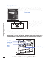
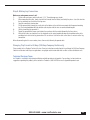
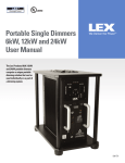
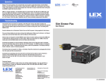
Lex Products Corporation
15 Progress Drive
Shelton, CT 06484
203.363.3738
203.363.3742 Fax
Lex West
11847 Sheldon Street
Sun Valley, CA 91352
818.768.4474
818.768.4040 Fax
www.lexproducts.com
[email protected]
800.643.4460
PowerGATE TM
60 A Company Switch
US P at. No. 7,136,278 B2
FOR USE IN AREAS NOT READILY ACCESSIBLE BY THE GENERAL PUBLIC
LBL-C S4 00 rev 0 01
US Patent
No. 7,136,278 B2
(U.S.A. and
Canada)
PowerGATE™
IEC 60309 Pin & Sleeve Company Switch
Installation Instructions and User Manual
LM-CS-PS Rev001
Switches & Panels
Table of Contents
Introduction..........................................................................................................................................................................3
Step 1: Installing the Company Switch..................................................................................................................................3
Step 2: Tools Needed............................................................................................................................................................4
Step 3: Mounting the Unit.....................................................................................................................................................5
Step 4: Wiring the Unit..........................................................................................................................................................6
Step 5: Isolating Chassis Ground (If applicable)...................................................................................................................7
Step 6: Pre- Power Up Check List.........................................................................................................................................8
Step 7.1: Powering Up .........................................................................................................................................................8
7.2: Troubleshooting......................................................................................................................................................9
Company Switch
Step 8: Operation & Use.....................................................................................................................................................10
2
Step 9: Making Lug Connections........................................................................................................................................11
Lex Products Pin & Sleeve Company Switch User Guide
Introduction
The Lex PowerGATE™ Company Switch has been specifically designed for temporary access to safe power in applications
such as:
•
•
•
•
•
Theaters
Convention Centers
Studios
Theme Parks
Recreational Facilities
Pin & Sleeve Company Switch Catalog Numbers
60 Amp
CS-60F-D5PS1
100 Amp
CS-100F-D5PS1
Manual Notes
Illustrations shown throughout this manual are of the 60 Amp Type 1 indoor Company Switch. However, they are also
representative of the 100 Amp Type 1 indoor Company Switch.
Step 1: Installing the Company Switch
WARNING: RISK OF ELECTRIC SHOCK, EXPLOSION OR ARC FLASH
• Apply appropriate personal protective equipment (PPE) and follow safe electrical
work practices. See NFPA 70E.
• This equipment must be installed and serviced by a licensed electrician only.
• Turn off all power supplying this equipment before working on or inside equipment. Lockouts/tagouts
are recommended.
• Always use a properly rated voltage sensing device to confirm power is off.
• Replace all devices, doors and covers before turning on power to this equipment.
Failure to follow these instructions can result in serious injury or death.
D
External Layout:
A: Main switch,
B: LED phase indicator lights
C: Connection chamber access door
D: Mounting ears, (2) located on the
bottom and (2) located on the top
of the unit.
PowerGATE TM
60 A Company Switch
US P at. No. 7,136,278 B2
FOR USE IN AREAS NOT READILY ACCESSIBLE BY THE GENERAL PUBLIC
LBL-C S4 00 r ev 0 01
A
L B L -C SG C re v 0 0 1
A
B
B
C
Ground
WARNING
RISK OF ELECTRICAL SHOCK
A) EQ UIP MENT G ROUNDING CONNECTORS ( GROUND)
B) GRO UNDE D CIRCUIT CONDUCTOR CONNECTO RS (NEUTRAL)
C) UNG RO UNDED CONDUCTOR CONNECTORS
DISCONNECTION MUST BE MADE IN REVERSE ORDER
LBL -CSWRN
C
FOR USE BY QUALIFIED PERSONNEL ONLY
THE ROU TING OF POR TABLE SUPPL Y CONDUC TOR S,
THE MAKIN G AND BREAKING OF SUPPLY CONNECTORS,
AND TH E ENERGIZATION AND DE-ENERGIZATION OF
SUPPLY SERVIC ES SHALL BE PERFORMED BY
QUALIFIED PERSONNEL ONLY.
LBL-CSQP
D
800.643.4460 • www.LexProducts.com
Figure 1
3
External Layout:
F: G: H: I: Shunt trip interlock
Internal light
Lug output connector access door
Pin & sleeve receptacle
F
H
G
Company Switch
I
Figure 2
Step 2: Tools Needed
• Lineman’s pliers
• Utility knife
• Set of screwdrivers
• Wrenches to connect the conduit into the unit
• 3/8" Allen key for making lug connections
• A hole saw or hole punch for providing an access hole in the cabinet for the conduit connection
• An insulation stripping tool, and cutter to provide square cut ends of the cables
• Mounting hardware (not included with the Lex Products PowerGATE™ Company Switch)
DETAIL B
SCALE 1 / 2
4
Lex Products Pin & Sleeve Company Switch User Guide
Step 3: Mounting the Unit
Remove upper panel to expose main switch connections and to make the unit easier to mount.
• D
etermine the specific location to install the unit and confirm that the
mounting surface will support the full weight of the Company Switch
plus connected cables.
• M
ounting ears are provided on positions 1 & 2 on the top and 3 & 4
on the bottom (see figure 4).
• The mounting hole pattern dimensions are:
CS100; CS60
Figure 3
Horizontal
Vertical
14.00”
37.00”
The minimum clearance (free space) from bottom of the unit to the nearest flat surface needs to be at least 24” to allow
clearance for a cable with a pin & sleeve connection. A mounting height of 44” above finished floor to the bottom of the panel
is recommended.
Hold unit into place and level, then mark the mounting hole locations. Drill and temporarily mount the unit.
While unit is mounted, determine the desired conduit location.
IMPORTANT:
NOTE 1: Bend radius requirements dictate that the conduit for incoming power may only enter the cabinet from the top of the cabinet. Conduit entry from the sides or back of the cabinet is not permitted.
NOTE 2: When connected to the box, the completed conduit must be a minimum of at least one inch
from any of the top edges for proper clearance.
Remove the unit and cut the conduit hole. Cover the main switch during this operation to assure metal filings do not make
contact with the switch.
Remount the unit permanently and attach and tighten conduit.
Mounting tab locations and conduit placement:
1
2
NOTE 1
NOTE 2
1" Min. from all edges.
4
3
800.643.4460 • www.LexProducts.com
Figure 4
5
Step 4: Wiring the Unit
The Lex PowerGATE™ Company Switches with pin & sleeve connections are available in (2) ratings: 100 Amp, 3 Phase,
120/208Y VAC and 60 Amp, 3 Phase, 120/208Y VAC .
The recommended input (contractor direct wire) wire gauge for these units is as follows:
• 60 Amp: #4 AWG minimum
• 100 Amp: #2 AWG minimum
With the conduit in place, confirm the main source of power is off. Once assured the main power source is off, pull the power
cables into the unit.
Company Switch
Follow the chart provided below for strip length and torque required to secure cables to binding lugs. Do not damage any
strands while stripping cable. Cable ends need to be cut square.
Circuit Breaker
Wire Gauge Range
350 kcmil - 6 AWG
Ground & Neutral Lugs
350 kcmil - 6 AWG
Torque (lb.-in.)
275
See table behind
Chamber Access Door
1-1/8”
NOTE: Fine stranded wire must be sleeved with copper shim stock before inserting into lugs or strands may
interfere with threads of wire binding screw, resulting in false torque indication.
Wire Installation
Strip the cable to the length indicated in the table above. To install, secure the ground first, followed by the neutral, then the phases.
Place the appropriate cables into the lugs. Using a 3/8" Allen wrench, torque the screw to the torque value indicated in the table above.
Neutral
Ground
Blue (Phase C)
Red (Phase B)
Black (Phase A)
Figure 5
6
Strip Length
1-1/8”
Lex Products Pin & Sleeve Company Switch User Guide
Step 5: Isolating the Chassis Ground
To isolate the chassis from ground, proceed as follows:
The chassis ground (C.G.) termination is located next to the main ground cable. To isolate this ground:
1) Remove the nut holding the chassis ground lug to the threaded stud.
2) Wrap the chassis ground mounting lug with electrical tape or shrink wrap, if available.
3) Using a plastic wire tie, secure the chassis ground to the main ground cable.
4) Confirm that the chassis ground is secured in a way that it cannot come into contact with any of the metal
surfaces within the cabinet.
Chassis Ground
Figure 6
800.643.4460 • www.LexProducts.com
7
Step 6: Power-Up Preparation
1) B efore energizing the unit, confirm that all connections are correct and secure, and that lugs are torqued to the proper
amount.
2) Check the area to confirm that there is no debris left over from drilling and that no tools are left in the cabinet.
3) Replace front panel and fasten securely.
4) Confirm lower panel door is closed and secured. Note that as a safety feature of this device, the circuit breaker will be
tripped when the door is opened.PowerGATE TM
5) Turn on power supplying the Company Switch.
60 A Company Switch
Step 7.1: Powering Up
US Pat. No. 7,136,278 B2
FOR USE IN AREAS NOT READILY ACCESSIBLE BY THE GENERAL PUBLIC
LBL-C S4 00 r ev 0 01
Company Switch
Turn the power lever to the ON position. LEDs for the ground and each phase will illuminate, confirming continuity.
LB L-C SG C rev 001
A
B
C
Ground
Figure 7
WARNING
RISK OF ELECTRICAL SHOCK
A) EQUIPMENT GROUNDING CONNECTORS (GROUND)
B) GROUNDED CIRCUIT CONDUCTOR CONNECTORS (NEUTRAL)
C) UNGROUNDED CONDUCTOR CONNECTORS
DISCONNECTION MUST BE MADE IN REVERSE ORDER
LBL-CSWRN
FOR USE BY QUALIFIED PERSONNEL ONLY
8
THE ROUTING OF PORTABLE SUPPLY CONDUCTORS,
THE MAKING AND BREAKING OF SUPPLY CONNECTORS,
AND THE ENERGIZATION AND DE-ENERGIZATION OF
SUPPLY SERVICES SHALL BE PERFORMED BY
Lex Products Pin & Sleeve Company Switch User Guide
QUALIFIED PERSONNEL ONLY.
LBL-CSQP
Step 7.2: Troubleshooting
WARNING: RISK OF ELECTRIC SHOCK, EXPLOSION OR ARC FLASH
• Apply appropriate personal protective equipment (PPE) and follow safe electrical
work practices. See NFPA 70E.
• This equipment must be installed and serviced by a licensed electrician only.
• Turn off all power supplying this equipment before working on or inside equipment. Lockouts/tagouts
are recommended.
• Always use a properly rated voltage sensing device to confirm power is off.
• Replace all devices, doors and covers before turning on power to this equipment.
Failure to follow these instructions can result in serious injury or death.
Troubleshooting
Unit trips immediately when powered
LEDs do not illuminate when unit is powered
Circuit breaker trips under rated ampacity
Ensure the lower panel door is closed and secured
Turn main power switch off and check the fuses located to the
left of the LEDs
Contact the Lex Products Technical Services team for
instructions on adjusting the trip delay time if the circuit
breaker appears to be tripping too quickly, due to inrush
current. Technical Services can be contacted 24/7 at
855-539-1002 or by email at [email protected].
800.643.4460 • www.LexProducts.com
9
L B L -C SG C re v 0 0 1
A
B
C
Ground
Step 8: Operation and Use
WARNING
RISK OF ELECTRICAL SHOCK
A) EQ UIP MENT G ROUNDING CONNECTORS ( GROUND)
B) GRO UNDE D CIRCUIT CONDUCTOR CONNECTO RS (NEUTRAL)
C) UNG RO UNDED CONDUCTOR CONNECTORS
DISCONNECTION MUST BE MADE IN REVERSE ORDER
LBL -CSWRN
The circuit breaker switch has a lockout/tagout feature that can be used to secure
the switch in the off position. First, lift the gray tab on the hub of the circuit
breaker lever. Once lifted, up to three locks may be attached to the tab, locking the
handle in the off position.
Lockout/Tagout
FOR USE BY QUALIFIED PERSONNEL ONLY
THE ROU TING OF POR TABLE SUPPL Y CONDUC TOR S,
THE MAKIN G AND BREAKING OF SUPPLY CONNECTORS,
AND TH E ENERGIZATION AND DE-ENERGIZATION OF
SUPPLY SERVIC ES SHALL BE PERFORMED BY
QUALIFIED PERSONNEL ONLY.
Company Switch
LBL-CSQP
The external connection wire access is located at
the bottom of the unit and the connections are made
inside the connection chamber, behind the lockable
door. The large hole is provided for a cable with a
pin & sleeve connector and the smaller holes are
provided for stripped wire connections.
The stripped wire lug connector access holes are located on the phenolic panel, and the securing screw lugs are located
behind the hinged phenolic door as shown below (Figure 8).
An access hole for the pin & sleeve receptacle is provided on the aluminum panel as shown in the illustration above.
NOTE: If the power is ON and the door is opened, the shunt trip interlock will trip the breaker OFF. As a
personal safety measure, the breaker should be switched to the OFF position before the door is opened.
Phase C - Blue
Phase B - Red
Phase A - Black
Neutral
Ground
Pin & Sleeve Receptacle
Figure 8
10
Lex Products Pin & Sleeve Company Switch User Guide
DETAIL D
SCALE 1 / 2
Step 9: Making Lug Connections
Make sure main power source is off.
1)
Cut the cable end square and strip the wire 1-1/2”. Do not damage any strands.
2)When connecting the cables, always start with the Ground, then the Neutral, and finally the phases. Insert the wire into
the lug and torque per the label on the lug cover.
4)
Open the connection chamber door.
5)Pull the ground cable through the smaller hole in the bottom of the unit that corresponds with the ground mounting
lug. The spring loaded door will help hold the cable in place while the wires are connected and torqued.
6)
Start by connecting the ground first.
7)
Torque the ground to the proper specification, then continue with the neutral followed by the three phases.
8)When all the cables are connected, use the wing bolts on the spring loaded cable door to clamp down on the cable,
providing strain relief for the lug connections. Be sure to leave slack in the cable so that there is no strain on the lug
connections.
When disconnecting, do it in reverse order: phases then neutral, follow by the ground cable.
Changing Trip Current to 60 Amp (100 Amp Company Switch only)
Please contact the Lex Products Technical Services Team for instructions on adjusting the trip setting of the 100 Amp Company
Switch circuit breaker to 60 Amps for applications using lighter cable to feed audio racks or other smaller distribution racks.
Technical Services Team
Lex Products is available to help during installation and with operation for all products. For questions, technical advice or
suggestions regarding this product, please contact Lex Products at 855.539.1002 or email [email protected].
800.643.4460 • www.LexProducts.com
11
PowerGATE™
Switches & Panels