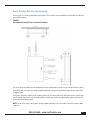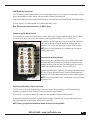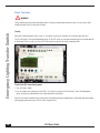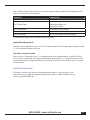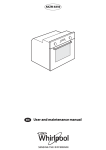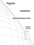
1
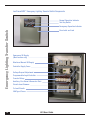
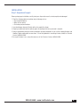
Lex Products Corporation
15 Progress Drive
Shelton, CT 06484
203.363.3738
203.363.3742 Fax
Lex West
11847 Sheldon Street
Sun Valley, CA 91352
818.768.4474
818.768.4040 Fax
www.lexproducts.com
[email protected]
800.643.4460
PowerGATE™
Emergency Lighting Transfer Switch
Installation Instructions and User Manual
LM-ELTP Rev. 000
Switches & Panels
Table of Contents
Introduction.........................................................................................................................................................................3
Lex PowerGATE™ Emergency Lighting Transfer Switch Components..................................................................................4
INSTALLATION
Emergency Lighting Transfer Switch
Step 1: Unpack and Inspect.................................................................................................................................................. 5
2
Step 2: Mounting the ELTS Cabinet...................................................................................................................................... 6
Step 3: Planning Wire Entry into the Cabinet....................................................................................................................... 7
Step 4: Connecting Power.................................................................................................................................................... 8
Step 5: Operation............................................................................................................................................................... 10
Technical Services Team.................................................................................................................................................... 11
LEX User Guide
Introduction
This manual details the installation and use of your Lex Emergency Lighting Transfer Switch. Before installation read this
manual in its entirety. Store this manual in a safe location for future reference.
How to use this manual:
This manual covers two product variants
• LELTS–XX-1 has individual 120VAC, 20A circuit emergency power feeds for each output circuit (Discrete feed)
• LELTS-XX-3 has a single 120/208 3Ø emergency power feed (Main feed)
For the remainder of the document the different variants will be referred to as “discrete feed” and “main feed”.
WARNING
This equipment has the potential to be the source of an electric shock hazard. Take extreme caution when the cabinet door is
opened and the system is energized.
This equipment should only be installed, commissioned and serviced by qualified service personnel.
Tools Needed:
• Blade screwdriver (3/16” blade)
• Phillips screwdriver
• Metric Allen key set (Main feed panels only)
• Socket wrench for mounting bolts
• Drill suitable for drilling holes in wall to mount the panel
• Metal punches to make conduit entry holes in cabinet
• Wire strippers
• Pliers
Anchors suitable for the wall that the ELTS is to be mounted on are required, and are not included.
800.643.4460 • www.LexProducts.com
3
Lex PowerGATE™ Emergency Lighting Transfer Switch Components
Normal Operation Indicator
Test Key Switch
Emergency Lighting Transfer Switch
Emergency Operation Indicator
Door Latch and Lock
Emergency 3Ø Supply
(Main version only)
Monitored Normal 3Ø Supply
Controller Supply Fuses
Voltage Dropout Adjustment
Programmable Logic Controller
Transfer Relays
Auxiliary, Fire Alarm & Generator Start
Circuits from Dimmers
To Load Circuits
20A Type J Fuses
4
LEX User Guide
INSTALLATION
Step 1: Unpack and Inspect
Before you begin your installation, carefully check your shipment to ensure it arrived complete and undamaged.
1. Check the shipping container for obvious physical damage such as:
• Torn or opened container
• Water stains or wetness
• Crushed or punctured container
2. If you find damage, document it to help with a claim against the shipper,
3. Unpack your order and check the contents against the packing list to ensure your order is complete.
4. Open the cabinet door and check for loose components or broken components as the result of shipping vibrations and
handling. Tighten anything that has come loose. If it can’t be tightened or if something is broken, contact Lex Technical
Services at 800.643.4460.
5. For any of the above issues, or any other concerns, call Lex Customer Service at 800.643.4460
800.643.4460 • www.LexProducts.com
5
Step 2: Mount the ELTS Cabinet
When considering the mounting location and planning the installation of the ELTS, take into account the following:
1. D
epending on the number of circuits and features of your system, enclosure size will vary. Consider the overall cabinet
mounting dimensions (Height, Depth and Width) when selecting the mounting location.
Emergency Lighting Transfer Switch
2. L eave adequate space around the cabinet for entry. You must mount the cabinet with sufficient front clearance (minimum
3 ft, 2 inches) to allow the door to open completely.
6
3. E nsure that there is adequate space around the cabinet for conduit. On Main Feed cabinets, the emergency feed conduit may
require additional space to meet NEC bend radius requirements.
4. M
ount the cabinet on a load bearing wall, in a location where it will not be subject to tampering or vandalism. Choose a
location where it will be the most likely to be secure from damage from fire, flood, or other conditions and incidents that will
require its use. If there are any doubts about about a location’s suitability, contact Lex Technical Services.
5. D
o not install the cabinet inside any other electrical or confined enclosure provided. Anchors suitable for the wall material
will be required.
After determining where to mount the cabinet, make sure you have adequate equipment to lift and support the cabinet in place
while securing it to the mounting location.
The cabinet has pre-drilled mounting holes in each of the 4 corners. Secure the cabinet to the mounting location using the
7/16” diameter screws (not included). Anchors suitable for the wall the panel is to be mounted on will be required and are not
included.
LEX User Guide
Step 3: Planning Wire Entry into the Cabinet
Refer to Figure 1 for recommended conduit entry locations. Please note that main feed and discrete feed models have different
terminal block locations.
FIGURE 1
Recommended Conduit Entry Locations Into Cabinet
For ease of wiring, the product has been designed so all electrical connections terminate in the top and right side of the cabinet.
On the Main Feed series panels, the emergency power conduit enters the top of the panel directly above the lugs marked 208V
Emergency Power.
For Discrete Feed panels, conduits for the emergency feed circuits, the normal feed circuits and the load circuits, enter the right
side of the panel, close to their respective terminal blocks. Control, normal power sensing and options connect within the areas
noted in the example diagram above.
NOTE: Do not run the control, normal power sensing, or option conductors in the same conduit used for the emergency power
conductors.
800.643.4460 • www.LexProducts.com
7
Step 4: Connecting Power
WARNING
To prevent death or serious injury due to electrical shock, both normal and emergency power must be turned off during the
installation, servicing or maintenance of the system.
Emergency Lighting Transfer Switch
Connecting Emergency Power:
Main Feed
For the Main Feed series, the emergency power lugs are located in the top center of the cabinet. Create an appropriately sized hole for
the conduit directly above the power lugs. Install the conduit and pull the emergency power conductors into the cabinet.
Connect the appropriate conductor to the corresponding lug. Tighten each phase conductor and neutral as follows:
Wire Size
350-#3/0
2/0-#1
#2-#6
#8-#14
Torque
200 lbs-in
100 lbs-in
80 lns-in
35 lbs-in
The Main Feed terminal blocks support wire sizes from #14 to 350kcmil. Ground is from #6AWG to 250kcmil.
Discrete Feed
On the Discrete Feed series panels, connect each emergency supply circuit to the terminal block marked 120V Emergency Power
Inputs, located on the right side of the cabinet. Tighten each connection to 25 lb-in.
Connecting Normal Power - Main Feed and Discrete Feed Versions:
The normal 120V circuits (often from dimmers) are connected to the terminal block marked as120V Normal Power Inputs, located on
the right side of the cabinet. Tighten each connection to 25 lb-in.
NOTE: Each normal circuit must be protected with a 20A circuit breaker located at the source cabinet.
The 120V Normal Power Input terminal blocks support the following wire sizes:
Connection
Line and neutral
Conductor Size
#22 - # 10 AWG
Connecting the Lighting Loads - Main Feed and Discrete Feed Versions:
The output load terminal block is on the right side of the cabinet.
Connect the load conductors to the 120V Load terminal block. Tighten each to 25 lb-in.
The terminal blocks support the following wire sizes:
Connection
Line and neutral
8
Conductor Size
#22 - # 10 AWG
LEX User Guide
208V Monitoring Connections:
The ELTS monitors the normal power to determine when a normal power failure occurs. Sensing wires are required from a 3-pole
breaker (not included) plus neutral, from the same normal feed as the circuits being transferred.
Connect the sensing wires from the normal feed to the three phases and neutral on the terminal block labelled 208V Monitored Power.
Terminals accept #22-#10 AWG conductors and should be tightened to 25 lb-in.
Note: Power sensing conductors must be 12 AWG or larger.
Connecting the Fire Alarm Interface:
You can connect your system to a fire alarm interface so that it switches to the emergency mode when the fire alarm is triggered.
The interfacing fire alarm system must be able to provide an open signal when it activates. This is a 120VAC circuit.
To connect the Fire Alarm signal wires, locate the terminal block marked Gen,
Aux, FA on the right side of the panel. Remove the shorting jumper from
between the “FA” terminals and connect your fire alarm control conductors.
NOTE: If the Fire Alarm activation circuit is not going to be used, leave the
shorting jumper in place.
Connecting the Auxiliary Interface:
You may connect your system to an auxiliary interface so that it switches to the
emergency mode when the auxiliary circuit is opened. An example of an Auxiliary device would be a remote key switch. Your auxiliary circuit must be able to
provide an open signal when it activates. This is a 120VAC circuit.
To connect the Auxiliary device signal wires, first locate the terminal block marked
GEN, AUX, FA on the right side of the panel. Remove the shorting jumper from
between the “AUX” terminal blocks and connect your auxiliary control conductors.
NOTE: If the Auxiliary activation circuit is not going to be used, leave the shorting jumper in place.
Connecting the Generator / Engine start circuit:
The ELTS can be used to start a standby generator in the event of a power failure or emergency event. Please note that your
generator must support the remote start feature. Consult your generator manual for details.
When the ELTS is in Emergency mode the GEN contacts are closed providing a closed circuit to the generator.
To connect the Generator Start signal wires, first locate the terminal block marked GEN, AUX, FA on the right side of the panel.
Connect your generator control conductors to the terminals marked GEN.
NOTE: Refer to your generator installation manual for start circuit wiring details.
800.643.4460 • www.LexProducts.com
9
Step 5: Operation
WARNING
Testing may only be performed by qualified personnel. Having an energized open cabinet presents a serious electric shock
hazard that could result in serious injury or death.
Emergency Lighting Transfer Switch
Testing:
10
Apply 208V monitoring power to the system. In 1 minute the circuit transfer contactors for the normal power will latch.
The PLC will display “Auto-Switch Monitoring Inputs” on the LCD. At this time the green indicator light in the cabinet door will
be illuminated. If this is not the case, then the PLC will need to be placed in the active monitoring mode.
To place the PLC in monitoring mode:
1. Press the “Menu” button
2. P ress the “down arrow” button and select “RUN”. Once in the run mode, the LCD will display “Auto-Switch Monitoring
Inputs” and the green indicator light in the cabinet door will be illuminated
Once the circuit transfer contactors for the normal power have latched and the green indicator lamp is illuminated, apply normal power
and emergency power to the system. Test the system using the test key.
LEX User Guide
When a condition is detected that will switch the system to the emergency mode, the condition will be displayed on the PLC
display. The messages that can be displayed are:
Connection
Auto-Switch Monitoring Inputs
Conductor Size
Normal operation, monitoring inputs
One or more of the 3 monitored phases are absent
Loss Of Normal Power
Undervoltage condition exists
Test Switch Activation
Aux. Input Activation
Fire Alarm Activation
Incorrect phase rotation
The test switch has been activated
The external Aux. control circuit has been opened
The Fire Alarm control circuit has been opened
The red indicator on the door will be illuminated during any failure mode.
Supply Voltage Measurements
Once power has been applied to the system, use an AC volt meter to confirm that all normal and emergency voltages are within
+/- 10% of rated nominal voltage for that circuit.
Time delays on transfer functions
When the system is first powered up, there is a 5 second delay before the normal power contactors are pulled in. Similarly,
when the system is switching from the emergency mode back to the normal mode there is a 1 minute delay from the time the
normal monitored inputs are recognized until the time the circuit transfer contactor are switched and the system is energized
with normal power.
Technical Services Team
Lex Products is available to help answer any installation or operation inquiries. If you have questions, need
technical advice or have suggestions regarding this product, please contact us at 800.643.4460 or email us at
[email protected].
800.643.4460 • www.LexProducts.com
11
PowerGATE™
Switches & Panels
ELTS_mn_v1_c