1
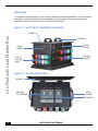
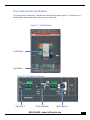
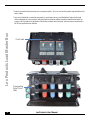
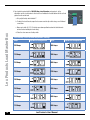
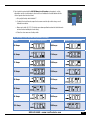
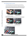
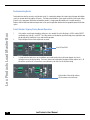
Lex Products Corporation
15 Progress Drive
Shelton, CT 06484
203.363.3738
203.363.3742 Fax
Lex West
11847 Sheldon Street
Sun Valley, CA 91352
818.768.4474
818.768.4040 Fax
www.lexproducts.com
[email protected]
800.643.4460
Load Master
Portable Power Distribution Box
LM-LOADMASTER
Operator’s Manual
Lex Products Load Master Box
Table of Contents
2
Specifications...................................................................................................................................................................2-3
Introduction......................................................................................................................................................................... 4
Lex Products Load Master Components.............................................................................................................................. 4
Shipment: Unpacking and Inspection................................................................................................................................... 5
Set Up
Step 1: Placement and Inspection of the Load Master Box................................................................................................... 5
Step 2: Setting Up the Load Master Distribution Box for Use............................................................................................... 6
Step 2.1: Making Cam-Type Connections................................................................................................................... 7
Step 2.2: Connecting the Input.................................................................................................................................... 8
Step 2.3: Connecting the Output.................................................................................................................................. 8
Figure 2.1: Maximum Ampacity of Feeder Cable......................................................................................................... 9
Figure 2.2: Temperature Rating of Feeder Cable.......................................................................................................... 9
Step 3: Adjusting the Circuit Breakers................................................................................................................................ 10
Step 3.1: Standard Circuit Breaker Adjustment Settings............................................................................................ 10
Figure 3.1: Circuit Breaker Diagram.......................................................................................................................... 11
Figure 3.2: 160-400 Amp Circuit Breaker Standard Adjustment Settings Diagram.................................................... 11
Figure 3.3: 100-250 Amp Circuit Breaker Standard Adjustment Settings Diagram.................................................... 11
Figure 3.4: 60-150 Amp Circuit Breaker Standard Adjustment Settings Diagram...................................................... 11
Step 3.2: Custom Circuit Breaker Adjustment Instructions...................................................................................12-13
Step 5: Powering Up.......................................................................................................................................................... 13
Troubleshooting Guide..................................................................................................................................................14-15
Technical Service Contact Information............................................................................................................................... 15
Lex Products User Manual
Shipment: Unpacking and Inspection
Check the shipment carefully to confirm it arrived complete and undamaged.
1. Unpack the shipment and check the contents against the packing list to ensure the order is complete.
2.Check the unit for loose or broken components, which might have resulted from shipping.
a. Inspect for signs of damage to wiring devices, device covers or circuit breakers.
b. Open and close the lid on the Load Master Box to determine whether it closes and latches properly.
3.If there is any damage to the Load Master Box, contact Lex Products Technical Services toll free at (855) 539-1002
or email
[email protected].
4. For any other questions, call Lex Products at (800) 643-4460.
800.643.4460 • www.LexProducts.com
3
Introduction
This manual details the installation and use of the Lex Products Load Master line of power distribution boxes. This power distribution
box provides a convenient way to adjust the overcurrent protection of the output receptacles. Please review this manual prior to
operating the Load Master box. Store this manual in a safe location for future reference.
Figure 1.1: Lex Products Load Master Components
Lex Products Load Master Box
Hinged Lid
Lid Handles
Locking
Latches
Lifting
Handles
Cam-type
Output(s)
2 sets of
Cam-type
Inputs
Figure 1.2: Top view with lid open
Hinged Lid
Adjustable
Circuit Breakers
Lifting
Handles
Dip Switches
4
Lex Products User Manual
SETTING UP THE LOAD MASTER DISTRIBUTION BOX
Set up of the Lex Products Load Master power distribution box is to be performed by
qualified personnel only.
Step 1: Placement of the Load Master Box
The Load Master distribution box is designed for indoor and outdoor use. The base of the unit is designed to elevate live electrical
components above ground level. The Lex Products Load Master is UL Listed for use in wet locations, but is not to be operated near
standing water or in wet weather.
1.The Load Master box is a two man portable unit. When moving the Load Master box, use the lifting handles on the sides of
the box (Figure 1).
2. Place the Load Master Box in a level location with a dry and firm foundation within proximity of the power source and the
location requiring power.
3. Open the lid for the unit to confirm that the adjustable circuit breakers are in the OFF position.
Step 2: Making the Input Connections
WARNING
Before making connections to the Load Master box, make sure the power source feeding the box is OFF.
WARNING
Do not exceed the voltage rating (600 VAC Max.).
1.Locate the (2) sets of feeder cable that will be used to bring power to the Load Master box.
a.
4/0 cable must be used to connect the Load Master distribution box to the power source.
b.Note: if using the feed thru feature on model PH800-N2J-31AV1AX1AZ, connect the feed thru before the input,
making the Cam-type connections in the same manner and order as indicated for the input connection on page 6.
WARNING
Both sets of Cam extensions feeding the input must come from the same power source.
800.643.4460 • www.LexProducts.com
5
Step 2: Making the Input Connections Continued
Lex Products Load Master Box
2. Connect the bottom input row of Cam cables first, beginning with the ground cable (Green).
3. Push the connector into the male (Green) Cam panel mount receptacle with the screw on the connector facing up.
4. Rotate the connector clockwise at least 90 degrees until it stops to make sure it is secured in the locked position
1. Align the connector with the
corresponding color-coded receptacle
2. Insert the Cam connector into the
receptacle and rotate Cam connector at least
90 clockwise degrees to lock
5. Connect neutral (White) Cam cable second.
6. Push the connector into the male (White) Cam panel mount receptacle with the screw on the connector facing up.
7. Rotate the connector clockwise at least 90 degrees until it stops to make sure it is secured in the locked position
1. Align the connector with the
corresponding color-coded receptacle
2. Insert the Cam connector into the
receptacle and rotate Cam connector at least
90 clockwise degrees to lock
8. Repeat steps 3-4 to connect the Blue, Red and then Black phases in the same manner.
9. Connect the second (Top) row of the Cam input in the same manner and color order as detailed above.
When disconnecting, do so in reverse order starting with the phases (Black, Red and Blue), followed by the neutral (White) and finally
ground (Green).
6
Lex Products User Manual
Step 3: Adjusting the Circuit Breakers
The current level of the circuit breakers is adjustable to match the load of the output receptacles. The circuit breakers are
adjusted with dip switches located under a clear cover on each circuit breaker.
Figure 3.1: Circuit Breaker
On/Off Switch
Dip Switches
Figure 3.2: Dip Switches Diagram
Dip Switch “L”
Short/Instant Delay
Neutral Sensing
7
N
0
5
I2=
5
I1 =
04
08
16
32
800.643.4460 • www.LexProducts.com
1. Determine the load that will be placed on each set of output receptacles. This is the value that will need to be matched with the circuit
breaker settings.
Lex Products Load Master Box
2. Each circuit is labeled with a number that corresponds to a specific output for easy circuit identification. Determine which load
will be matched with each set of receptacles and circuit breakers based on the available range of the Load Master box model. For
example, a 400 Amp load must be paired with a 160-400 Amp receptacle and circuit breaker; a 60 Amp load must be paired with a
60-150 Amp receptacle and circuit breaker.
8
Circuit Label
Corresponding
Output Circuit
Label
Lex Products User Manual
Circuit Breaker Adjustment Settings
3. For a load to be paired with the 160-400 Amp circuit breaker and receptacle, set the dipswitches
on the circuit breaker to the closest level indicated in the table below with the set level greater than
the actual load.
a. Only adjust the dip switch labeled “L”
b. To adjust the circuit breaker, open the clear cover over the dip switch using a small flathead
screw driver.
c. Move each switch (A, B, C, D) into the up or down position based on the table below to achieve
the desired output current rating
d. Close the clear cover over the dip switch.
I1 =
160 Amps
I2=
In x (0.4+
Dipswitch
Configuration
In x Σ
)
L
A
B
C
D
0
0
0
0
160-400 Amp Circuit Breaker Adjustment Settings
Amps
Dipswitch Configuration
Amps
ABCD
0.0
4
0.0
8
0.1
6
0.3
2
288 Amps
t1
3s
12s
I=6I1
PR221DS
176 Amps
304 Amps
192 Amps
320 Amps
208 Amps
336 Amps
224 Amps
352 Amps
240 Amps
368 Amps
256 Amps
384 Amps
272 Amps
400 Amps
800.643.4460 • www.LexProducts.com
9
S I3=
I
10
b. To adjust the circuit breaker, open the clear cover over the dip switch using a small flathead
screw driver.
c. Move each switch (A, B, C, D) into the up or down position based on the table below to
achieve the desired output current rating
d. Close the clear cover over the dip switch.
100-250 Amp Circuit Breaker Adjustment Settings
Amps
Dipswitch Configuration
Amps
ABCD
I1 =
In x (0.4+
100 Amps
Dipswitch
t1
L Configuration
B
C
D
180 Amps
190 Amps
120 Amps
200 Amps
130 Amps
210 Amps
140 Amps
220 Amps
150 Amps
230 Amps
160 Amps
240 Amps
170 Amps
250 Amps
Lex Products User Manual
3s
12s
I=6I1
PR221DS
110 Amps
I2=
)
A
In x Σ(
S I3=
I
1
0
a. Only adjust the dip switch labeled “L”
0.0
4
0.0
8
0.1
6
0.3
2
0
0
0
0
Lex Products Load Master Box
4. For a load to be paired with the 100-250 Amp circuit breaker and receptacle, set the
dipswitches on the circuit breaker to the closest level indicated in the table below with the set level
greater than the actual load.
5. For a load to be paired with the 60-150 Amp circuit breaker and receptacle, set the
dipswitches on the circuit breaker to the closest level indicated in the table below with the
set level greater than the actual load.
b. To adjust the circuit breaker, open the clear cover over the dip switch using a small
flathead screw driver.
c. Move each switch (A, B, C, D) into the up or down position based on the table below to
achieve the desired output current rating
d. Close the clear cover over the dip switch.
I1 =
In x (0.4+
60 Amps
I2=
In x Σ(
)
S I3=
I
Dipswitch
Configuration
t1
L
A
B
C
D
0
0
0
0
60-150 Amp Circuit Breaker Adjustment Settings
Amps
Dipswitch Configuration
Amps
ABCD
108 Amps
3s
12s
I=6I1
PR221DS
66 Amps
114 Amps
72 Amps
120 Amps
78 Amps
126 Amps
84 Amps
132 Amps
90 Amps
138 Amps
86 Amps
144 Amps
102 Amps
150 Amps
800.643.4460 • www.LexProducts.com
11
1
0
0
a. Only adjust the dip switch labeled “L”
0.0
4
0.0
8
0.1
6
0.3
2
Lex Products Load Master Box
Step 4: Making the Output Connections
12
1.Select the appropriate guage feeder cable to match the load requirements of each circuit that will be in use.
2.Locate the sets of feeder cable that will be used to bring power from the Load Master box further downstream.
3. Connect the Cam cables to the output that corresponds to circuit (1) first, beginning with the ground cable (Green).
4. Push the connector into the male (Green) Cam panel mount receptacle with the screw on the connector facing up.
5. Rotate the connector clockwise at least 90 degrees until it stops to make sure it is secured in the locked position
1. Align the connector with the
corresponding color-coded receptacle
6. Connect neutral (White) Cam cable second.
7. Push the connector into the male (White) Cam panel mount receptacle with the screw on the connector facing up.
8. Rotate the connector clockwise at least 90 degrees until it stops to make sure it is secured in the locked position
1. Align the connector with the
corresponding color-coded receptacle
2. Insert the Cam connector into the
receptacle and rotate Cam connector at least
90 clockwise degrees to lock
2. Insert the Cam connector into the
receptacle and rotate Cam connector at least
90 clockwise degrees to lock
9. Repeat steps 3-4 to connect the Blue, Red and then Black phases in the same manner.
Lex Products User Manual
10. Connect the Cam set that is connected to circuit (1) to the input of the downstream power distribution box that matches the
load requirements of circuit (1). Connect the Cam set in the same manner and color order as detailed previously.
11. Repeat steps 3-10 for each additional circuit that will be in use on the Load Master Box, connecting the Cam cables in the
same manner and color order as detailed above.
When disconnecting the cables, do so in reverse order starting with the phases (Black, Red and Blue), followed by the neutral (White)
and finally ground (Green).
Step 5: Powering Up
Best practices dictate that loads are applied gradually (systematically) the first time the system is set up. If a circuit breaker cannot
be energized or trips, check the system for continuity and short circuits, and make the necessary corrections before proceeding.
1. Turn on the power source.
2. Turn the first circuit breaker required on the Load Master box to the ON position.
3. After switching on the first circuit on the Load Master box, turn corresponding circuits for the downstream power
distribution box to the ON position.
4. Repeat these steps for each additional circuit breaker that will be in use on the Load Master power distribution box.
800.643.4460 • www.LexProducts.com
13
Troubleshooting Guide
To help determine what has caused a circuit breaker to trip, it is important to configure the simplest possible power distribution
system set up under which the problem still occurs. The loads connected to the system might exceed the circuit breaker rating,
in which case a larger power distribution unit would be needed. If a larger power distribution unit is needed, contact Lex
Products with the load information and requirements of the specific application to determine the appropriate power distribution
system.
1.Verify whether circuit breaker long delay settings are set as needed: Ensure the N setting is at 100% and the ON/OFF
functionality next to the N is set to OFF. These dip switches are intended for specialized single phase applications and
do not apply to the Load Master series under normal operation.
2.
Retry turning on the circuit after adjustments are made.
Set to OFF and 100%
C
D
t1
0
0
0
0
B
3s
12s
ON
100
S I3=
I
)
%
T2
0.1s
0.25s
I=6I1
I=8In
Test
+
OFF
50
A
L
I2=
In x Σ(
)
0
0
0
0
In x (0.4+
0.0
4
0.0
8
0.1
6
0.3
2
I1 =
1
1.5
2
5.5
3.If a large inductive load such as an air conditioner was turned on when the circuit breaker tripped, raise inrush
settings or increase the trip time delay. The inrush settings can be adjusted by turning on the dip switches for I3. All
dip switches up will result in the maximum inrush tolerance of ten times the circuit breaker rating.
-
N
B
C
D
0
0
0
0
L
t1
3s
12s
I=6I1
S I3=
I
ON
100
I2=
In x Σ(
)
A
)
%
T2
0.1s
0.25s
I=8In
OFF
50
In x (0.4+
0
0
0
0
I1 =
1
1.5
2
5.5
PR221DS
0.0
4
0.0
8
0.1
6
0.3
2
Lex Products Load Master Box
Circuit Breaker Tripping During Normal Operation
Test
+
-
N
PR221DS
14
Lex Products User Manual
l3 dip switches: Move all dip switches
UP for maximum inrush tolerance
Troubleshooting Guide Continued
Circuit Breaker Tripping When Powering Up
1.
Follow the steps outlined for circuit breakers tripping during normal operation.
2.
If the issue persists, disconnect the output connections from the circuit breaker that is tripping.
3.Turn on all circuit breakers. If the circuit breaker trips, contact Lex Products for technical assistance. If the circuit
breaker does not trip proceed to the next step.
4.
Connect the cable to the corresponding circuit breaker outlets and turn off all attached loads.
5.
Turn on the circuit breaker.
a.
If the circuit breaker trips, disconnect cabling used and check for short circuits.
b.Turn off all circuit breakers, check the cabling connected to the Load Master, and check connected loads for
shorts circuits.
How to check for a Load Master for short circuits
1.
Disconnect incoming power from the Load Master box.
2.
Turn on circuit breaker(s) for the circuit(s) to be tested.
3.Using a continuity meter or a multimeter, set to continuity/resistance mode and connect one probe to the input ground
(green) Cam-type connector brass.
4.
Take the other probe of the meter and check if there is continuity between each Cam-type connector and ground.
5.If there is continuity (R < 1 kΩ, or the meter lights up or beeps), there is short circuit present. Contact Lex Products
Technical Services department.
6.If there is no continuity, repeat step 3 and 4 checking if there is continuity between the neutral (white) Cam-type
connector and the other Cam-type connectors. If continuity is detected, there is a short circuit present. Contact Lex
Products if a short circuit is detected.
Technical Support
Lex Products is available to help answer any installation or operation inquiries. For any questions or technical advice, please call
Technical Services 24 hours per day, 7 days per week at 855.LEX.1002 or email [email protected].
800.643.4460 • www.LexProducts.com
15
PowerHOUSE™
Portable Distribution Boxes