1
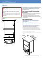
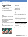
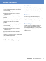
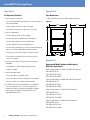
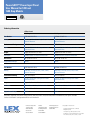
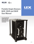
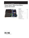
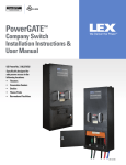
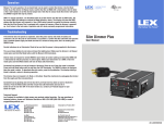
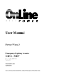
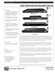
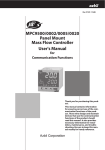
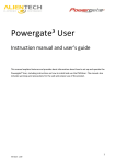
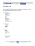
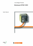
PowerGATE™ Switches & Panels PowerGATE™ Power Input Panel User Manual for 1200 and 1600 Amp Models A safe, reliable and convenient means of connecting temporary power for disaster relief applications PowerGATE™ Power Input Panel Contents Important: 2 Table of Contents 3 Prior to Installation 3 Shipment and Inspection 4 Product Features This manual contains information critical to the proper installation and operation of the Lex Products PowerGATE™ Power Input Panel. Be certain to read and understand all instructions prior to installation and operation. 5 - 6 Installation 7 - 8 Set-up 8 - 9 Disconnection 9 Limited Warranty 9Maintenance 9 Technical Support Appendices 10 Pre-Operation and Maintenance Checklist 10 Parts Dimensions 10 Represented Model Numbers and Ratings 11 Warning Labels 2 Contact Lex Products: 800.643.4460 [email protected] NOTE: Must be installed in conjunction with transfer switch (Transfer Switch to be provided by a source other than Lex Products). PowerGATE™ Power Input Panel Prior to Installation: Site Preparation Prepare installation site according to local codes. The PowerGATE Power Input Panel is to be set on an exterior pad and secured to a building or secured to a pad using 3/8“ fasteners (See Figure 1). The surface where the PowerGATE Power Input Panel is to be secured must be capable of supporting the weight of the cabinet as well as the cable attached to it. – Proper clearance must be allowed in front of the PowerGATE Power Input Panel to allow for opening of access doors and attachment of externally connected cables. This distance should be no less than six (6) feet from the face of the panel. – While keylock protection is provided, access by unauthorized personnel and vandals should be taken into consideration when locating this device. The following should be taken into consideration when locating the PowerGATE power Input Panel: Shipment: Unpacking and Inspection – The PowerGATE Power Input Panel is designed for exterior operation ONLY Note: be careful in the use of sharp object when cutting packaging as scratching of outer coating may result in rusting. – Identify and meet local codes and local Authority Having Jurisdiction (AHJ) Perform a visual inspection to ensure all keylocks and doors are in functioning condition and that the panel integrity is intact. – To prevent carbon monoxide poisoning from improperly ventilated generator emissions, the Power Input Panel must be mounted outdoors only. The mounting location is to be carefully selected to allow convenient connection to a generator, and located a suitable distance away from any building openings or HVAC inlets. Figure 1 .38 33.14 27.44 Contact Lex Products: 800.643.4460 [email protected] 3 PowerGATE™ Power Input Panel Product Features Purpose-built Type 3R cabinet independently tested to current code Large copper bus bars with numerous locations for securing load wiring Keylocked access doors for ease of inspection, termination and prevention of unauthorized access Figure 2 Large upper termination chamber to ease cable routing and installation Cable access door for mechanical strain reduction and theft deterrence Figure 3 Industry-standard Series 16 single pole cam inputs for rapid termination during an emergency 4 Contact Lex Products: 800.643.4460 [email protected] PowerGATE™ Power Input Panel Installation WARNING The PowerGATE Power Input Panel is top heavy and therefore the center of gravity is well above the forklift slots (See Figure 4). Care must be taken to secure the device when it is lifted and moved. – Please note that the 1200 Amp versions weigh approximately 485 pounds and the 1600 Amp versions weigh approximately 505 pounds Figure 4 The installation of the PowerGATE Power Input Panel should be carried out by qualified personnel in accordance with local electrical codes. Step 1: Fasten the PowerGATE Power Input Panel to secure base 1. Base must be level and plumb to allow for proper drainage from the PowerGATE Power Input Panel weep holes 2. Fastening onto an external pad using 3/8” fasteners must be completed prior to proceeding with any terminations (See Figure 1 for hole spacing) Step 2: Installing the Conduit NOTE: Conduit to enter through the top or top rear of the device (See Figure 5) NOTE: To maintain TYPE 3R Rating compliance for the enclosure, proper sealing procedures must be followed. This is to include, but not limited to, the use of proper gaskets. 1. Open upper to door to expose termination chamber 2. Conduit to be sized according to cabinet and cabling rating 3. It is recommended that a knockout punch be used to cut hole for conduit. Place the punch on the inside of the enclosure and draw the punch through to the die on the outside. 4. Vacuum entire upper chamber to ensure no metal shavings are left behind Figure 5 Forklift ports Contact Lex Products: 800.643.4460 [email protected] 5 PowerGATE™ Power Input Panel Installation – Continued Step 3: Wiring the Bus Bars Step 4: Determine Phase Rotation This information will be needed when connecting a generator. WARNING Ensure circuit breakers are OFF and the transfer switch is locked out from utility power prior to connection. A: Determine phase rotation of the utility power. – Connect a phase rotation meter to a three phase power source in the building and record whether the building is wired clockwise or counter-clockwise Failure to install transfer switch will create the potential for the generator to energize utility lines and endanger utility personnel. Conversely, utility lines may energize the PowerGATE Power Input Panel and endanger generator personnel. B: Apply the provided label (Figure 6) to the inside of the PowerGATE Input Panel on the inside of the cam connection chamber door (Figure 7). DANGER The PowerGATE Power Input Panel HIGH is for useVOLTAGE only for OUT connection of a generator to the sourceKEEP terminals of a transfer switch, such that the inletsHAUTE are only energized from TENSION the generator. NE PAS TOUCHER LBL-PGIP-D1 3Ø Power Clockwise DANGER – The recommended input (contractor direct wire) wire gauge for this unit is 350 MCM Do not start the generator until all connectors are connected or made to be inaccessible. Any terminal may be energized when any cable is connected. De-energize cables at the generator prior to connecting or removing any connectors Apply 1 to inside door of Input Panel Connection Chamber – Terminal crimp rings to have 1/2” opening Ne pas mettre la génératrice en marche avant que tous les câble est raccordé. Débrancher les câbles à la génératrice avant de brancher ou de débrancher les connecteurs – Use 1/2” bolts tightened to ninety-eight (98) foot pounds of torque WARNING 3. S ecure a solid and permanent electrical ground between the AVERTISSEMENT Risk of Electric Shock building ground point and the PowerGATE Power Input Panel Plug connection should be in the following order: 1) Equipment grounding conductor connectors, 2) Grounded circuit conductor connectors, and 3) Ungrounded conductor connectors. Disconnection should be in the reverse order Risque de choc électrique Le raccordement devrait être effectué dans l’ordre qui suit: 1) Conducteur de mise à la terre de l’appareillage 2) Conducteur du circuit mis à la terre 3) 3) Conducteurs non mis à la terre La mise hors tension doit se faire dans l’ordre inverse Lex Products Part Number – LBL-PGIP-ROTATION LBL-PGIP-D2 soient connectés ou rendus inaccessibles. 2. Secure ring terminals to bus barconnecteurs N’importe quelle borne peut être mise sous tension si un 3Ø Power Counter Clockwise LBL-PGIP-ROTATION 1. Secure ring terminals on ends of cable Figure 6 Figure 7 4. V acuum entire upper chamber to ensure no metal shavings are left behind LBL-PGIP-W1 NOTE: Conduit shall NOT be relied upon to provide grounding protection to tap box WARNING Three phase power systems consist of three phase or hot conductors that are shifted by 120 degrees. Three phase loads such as motors may only work properly if the phases are connected in the correct order. Some motors may work with connected improperly, but will operate backwards. Utility power and electrical generators may be wired either in a clockwise or counter-clockwise order. It is important that any generator connected to the PowerGATE input panel is connected in the same rotation (clockwise or counter-clockwise) as the utility power. A N LBL-A LBL-N B G C LBL-B Place rotation label here LBL-G Step 5: Conduct a safety test to ensure proper installation TYPE 3R RAINPROOF Transfer Switch Accessory Model LBL-PGIP Rating S/N Made in USA 6 www.lexproducts.com 1-800-643-4460 Contact Lex Products: 800.643.4460 [email protected] LBL-C Do not attempt to use the PowerGATE Power Input Panel prior to installation and completing the Pre-Operation and Maintenance Checklist under Appendix A. C LBL-C PowerGATE™ Power Input Panel Set-up A: Review Pre-Operation Checklist under Appendices A prior to operation (page 10) WARNING DO NOT ATTEMPT CONNECTION WHILE CIRCUITS ARE LIVE – Do not use cables if they appear frayed – Do not use cable if connectors or plug do not seat properly – Do not use cables if any copper cabling is exposed 3. Continue with connections, beginning with the rear of the cabinet and working forward 4. Complete ALL Ground connections working from back to front prior to proceeding 5. Complete the Neutral (white) connections, beginning with the furthest from the front door Proper connection (See Figure 8): A. G rasp connector jacket and firmly Insert cam connector into cam plug – To limit risk of shock, disable generator automatic start to prevent unintended starting B. Push on cam connector jacket until connector fully seats in cam plug B: Determining phase rotation of generator 1. Disconnect generator from all loads if needed 2. C onnect a phase rotation meter to the output phases of the generator 3. Record generator phase rotation (clockwise or counter-clockwise) C. Rotate cam connector jacket counterclockwise until it stops 6. Continue with connections, beginning with the rear of the cabinet and working forward 7. Complete the Phase (hot) connections A. S hould the phase rotation of the generator (as determined in Step 5.B.3. above) and utility power (label found on the inside of the door for the Cam connection chamber) match, connect the Hots as follows: C: Making Cam Connections 1. Open lower chamber door 2. C omplete the Ground (green) connections, beginning with the furthest from the front door to the left Proper connection (See Figure 8): A. G rasp connector jacket and firmly insert cam connector into cam plug Generator Hot PowerGATE Power Input Panel Hot A A B B C C B. Should the phase rotation of the generator (as determined in Step 5.B.3. above) and utility power (label found on the inside of the door for the Cam connection chamber) NOT match, connect the Hots as follows: B. P ush on cam connector jacket until connector fully seats in cam plug C. Rotate cam connector jacket counterclockwise until it stops Figure 8 Generator Hot PowerGATE Power Input Panel Hot A B B A C C Contact Lex Products: 800.643.4460 [email protected] 7 PowerGATE™ Power Input Panel Set-up – Continued Disconnection Proper connection (See Figure 8): Step 7: Powering Up A. G rasp connector jacket and firmly Insert cam connector into cam plug B. P ush on cam connector jacket until connector fully seats in cam plug C. Rotate cam connector jacket counterclockwise until it stops 8. C ontinue with connections, beginning with the rear of the cabinet and working forward 9. C omplete ALL Phase connections working from back to front prior to proceeding 10. Make sure all connections are right and secure Step 6: Close and lock lower chamber door, allowing cables to exit through smaller cable door (See Figure 9) Figure 9 WARNING Power MUST BE supplied from a single generator 1. Start generator per manufacturer instructions 2. Toggle the transfer switch, diverting power from utility to generator feed Step 8: Disconnecting Circuits WARNING DO NOT ATTEMPT DISCONNECTING WHILE CIRCUITS ARE LIVE 1. To limit risk of shock, disable generator automatic start to prevent unintended starting – Open lower chamber door – Order of disconnect 2. Disconnect the Phase (hot) connections, beginning with the closest to the front door to the right Proper disconnection (See Figure 10): A. G rasp connector jacket firmly and rotate cam connector clockwise until it stops B. Firmly pull on connector until it separates from the plug C. Set aside 3. Continue with ALL Phase (hot) connections, beginning with the front of the cabinet and working from front to back Figure 10 8 Contact Lex Products: 800.643.4460 [email protected] PowerGATE™ Power Input Panel Limited Warranty 4. Complete disconnect of ALL Hot connections prior to proceeding 5. D isconnect the Neutral (white) connections, beginning with the closest to the front door Proper disconnection (See Figure 10): A. G rasp connector jacket firmly and rotate cam connector clockwise until it stops B. Firmly pull on connector until it separates from the plug C. Set aside 6. C ontinue with ALL Neutral (white) connections, beginning with the front of the cabinet and working from front to back 7. C omplete disconnect of ALL Neutral connections prior to proceeding 8. D isconnect the Ground (green) connections, beginning with the closest to the front door Proper disconnection (See Figure 10): A. G rasp connector jacket firmly and rotate cam connector clockwise until it stops When this PowerGATE Power Input Panel is installed and operated according to the manual’s instructions Lex Products will repair or replace any of its mechanical or electrical parts if they are found to be defective in material or workmanship within one year of the purchase date. Maintenance The PowerGATE Power Input Panel will require periodic maintenance. Lex Products recommends annual inspections to keep the panel in safe operating condition. Lex Products recommends that the Pre-Operation and Maintenance Checklist under Appendix A serve as a basis for annual inspection. Technical Support Lex Products Technical Service department is available 24/7 to assist in resolving issues by calling 1.855.LEX.1002 or emailing [email protected]. For any other information, please call Lex Products at 1.800.643.4460 or e-mail [email protected]. B. Firmly pull on connector until it separates from the plug C. Set aside 9. C ontinue with ALL Ground (green) connections, beginning with the front of the cabinet and working rearward 10. Complete disconnect of ALL Neutral connections prior to proceeding Step 9: Secure the three (3) keylocks to complete procedure Contact Lex Products: 800.643.4460 [email protected] 9 PowerGATE™ Power Input Panel Appendix A Appendix B Pre-Operation Checklist Parts Dimensions 1. Visual inspection of enclosure 1. Table with leader letters, part number and part description – Ensure the PowerGATE Power Input Panel is firmly secured to its base and/or building Figure 11 35.80 31.00 – Review conduit connection for signs of leakage – Ensure paint is intact with no signs of rust or corrosion 2. Open all chamber doors – Ensure chambers are dry and free of debris – Ensure that gaskets are pliable and no cracking exists – Ensure that door hinges are secure and lubricated 58.91 – Ensure that keylocks are intact and operational – Ensure that all load terminals are securely fastened and that the bolts are set at ninety-eight (98) foot pounds of torque – Ensure paint is intact with no signs of rusting or corrosion – Ensure electrical connections are intact with no signs of corrosion or cracking 3. R eview all safety labels and ensure that they are present and legible Appendix C – See Appendix D for label nomenclature and location Represented Model Numbers and Ratings of Multi-Row Input Panels – Replace as needed Specific model numbers for 1200A Delta 208Y/120V operation: 4. Inspect all portable cables –D o not use cables if they appear frayed –D o not use cable if connectors or plug do not seat properly –D o not use cables if any copper wiring is exposed 5. L ex Products Technical Service department is available 24/7 to assist in resolving issues. If you have any questions or need technical advice or suggestions regarding this product, please contact Lex Products at 203-363-3738 or e-mail [email protected]. PGIP1200-CRG15EI-S3 PGIP1200-CRG15EI-S3-BOY PGIP1200-CRG15EI-S3-BBB Specific model numbers for 1600A Delta 208Y/120V operation: PGIP1600-CRG15EI-S3 PGIP1600-CRG15EI-S3-BOY PGIP1600-CRG15EI-S3-BBB Specific model numbers for 1200A Wye 240V operation: PGIP1200-CRG12DI-S3 PGIP1200-CRG12DI-S3-BOY PGIP1200-CRG12DI-S3-BBB Specific model numbers for 1600A Wye 240V operation: PGIP1600-CRG12DI-S3 PGIP1600-CRG12DI-S3-BOY PGIP1600-CRG12DI-S3-BBB 10 Contact Lex Products: 800.643.4460 [email protected] PowerGATE™ Power Input Panel Appendix D Lex Products Part Number – LBL-PGIP-D1 WARNING AVERTISSEMENT 2.75" Do not start the generator until all connectors are connected or made to be inaccessible. Any terminal may be energized when any cable is connected. De-energize cables at the generator prior to connecting or removing any connectors Ne pas mettre la génératrice en marche avant que tous les connecteurs soient connectés ou rendus inaccessibles. N’importe quelle borne peut être mise sous tension si un câble est raccordé. Débrancher les câbles à la génératrice avant de brancher ou de débrancher les connecteurs LBL-PGIP-D2 2.75" HIGH VOLTAGE KEEP OUT HAUTE TENSION NE PAS TOUCHER DANGER LBL-PGIP-D1 2.75" DANGER 0.125 4.00" 4.00" Lex Products Part Number – LBL-PGIP-D2 Risk of Electric Shock Plug connection should be in the following order: 1) Equipment grounding conductor connectors, 2) Grounded circuit conductor connectors, and 3) Ungrounded conductor connectors. Disconnection should be in the reverse order Risque de choc électrique Le raccordement devrait être effectué dans l’ordre qui suit: 1) Conducteur de mise à la terre de l’appareillage 2) Conducteur du circuit mis à la terre 3) 3) Conducteurs non mis à la terre La mise hors tension doit se faire dans l’ordre inverse Lex Products Part Number – LBL-PGIP-W1 R 0.125 R 0.125 Lex P/N: LBL-PGIP-D1 Revision: NS Lex P/N: LBL-PGIP-D2 Revision: NS Lex P/N: LBL-PGIP-W1 Revision: NS Red color to be ANSI Z535.4 ‘Danger’ Red Red color to be ANSI Z535.4 ‘Danger’ Red Orange color to be ANSI Z535.4 ‘Warning’ Orange Materials to be the same or similar to LBL-CS400 Materials to be the same or similar to LBL-CS400 Materials to be the same or similar to LBL-CS400 Lex Products Part Number – LBL-A Lex Products Part Number – LBL-N LBL-PGIP-W1 Labels for Replacement 4.00" Lex Products Part Number – LBL-B Lex Products Part Number – LBL-C Lex Products Part Number – LBL-G Contact Lex Products: 800.643.4460 [email protected] 11 PowerGATE™ Power Input Panel User Manual for 1200 and 1600 Amp Models PowerGATE™ Switches & Panels Ordering information cETLus Listed 1200 Amp 1600 Amp Part Number PGIP1200-CRG15EI-S3 PGIP1600-CRG20EI-S3 Rating 1200 Amp, 3 Phase (H,H,H,N,G), 4 Pole, 5 Wire, 600 VAC Maximum 1600 Amp, 3 Phase (H,H,H,N,G), 4 Pole, 5 Wire, 600 VAC Maximum Environmental Rating TYPE 3R Rainproof TYPE 3R Rainproof Input (3) Sets of (5) 16 Series Cam-type color coded panel mount inlets (4) Sets of (5) 16 Series Cam-type color coded panel mount inlets Output Copper Bus Bar with 1/2” Holes Copper Bus Bar with 1/2” Holes Enclosure Powder Coated 12 Gauge Galvanized Steel Powder Coated 12 Gauge Galvanized Steel Dimensions 56” H x 30” D x 35” W 56” H x 30” D x 35” W Approximate Weight 485 lbs 505 lbs Part Number PGIP1200-CRG12DI-S3 PGIP1600-CRG16DI-S3 Rating 1200 Amp, 3 Phase (H,H,H,G), 3 Pole, 3 Wire, 600 VAC Maximum 1600 Amp, 3 Phase (H,H,H,G), 3 Pole, 3 Wire, 600 VAC Maximum Environmental Rating TYPE 3R Rainproof TYPE 3R Rainproof Input (3) Set of (4) 16 Series Cam-type color coded panel mount inlets (4) Set of (4) 16 Series Cam-type color coded panel mount inlets Output Copper Bus Bar with 1/2” Holes Copper Bus Bar with 1/2” Holes Enclosure Powder Coated 12 Gauge Galvanized Steel Powder Coated 12 Gauge Galvanized Steel Dimensions 56” H x 30” D x 35” W 56” H x 30” D x 35” W Approximate Weight 475 lbs 495 lbs BRB (Black, Red, Blue), BOY (Brown, Orange, Yellow), BBB (Black, Black, Black) and RGN (Reverse Ground Neutral) Cam options available. Contact a Lex Products sales representative for more information Lex Products Corporation 15 Progress Drive Shelton CT 06484 203.363.3738 203.363.3742 Fax Lex West 11847 Sheldon Street Sun Valley, CA 91352 818.768.4474 818.768.4040 Fax www.lexproducts.com [email protected] 800.643.4460 © Copyright Lex Products 2012 Produced in the United States of America All Rights Reserved. Lex Products logo and lexproducts.com are trademarks or registered trademarks of Lex Products in the United States, other countries, or both.