1
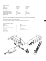
User Manual neodrives drive system Part 1 neodrives sMMI and motor Part 2 neodrives battery Part 1 USER MANUAL neodrives sMMI and motor (sMMI Firmwareversion 1.4.0.0) Contents 1. Introduction 1.2 Intended use of the neodrives components 1.3 Signs and symbols 1.4 Permissible operating conditions / operating sites 1.5 Standard scope of delivery (neodrives components) 1.6 Technical data 2 2 2 2 3 3 2. Controller 4 3. smart Man-Machine Interface (sMMI) 3.1 Fitting and removing the sMMI 3.2 Functions of the sMMI 3.2.1Switching on and off 3.2.2 Start menu 3.2.3 Dynamo function and start-up routine “light” (optional) 3.2.4 Selecting the assistance level 3.2.5 Activating recuperation 3.2.6 Braking assistant 3.2.7 Pushing aid 3.2.9 Travel modes 3.2.10 Displaying journey information (bike computer functions) 3.2.11 Information and warning symbols 3.2.13 Other settings 3.2.14 USB port 3.2.15 Programming options by the specialist dealer 3.2.16 Firmware updates and relaying them to the motor and battery 3.2.17 Note on the sMMI plugs 4 5 5 5 6 6 6 7 7 9 10 11 12 13 13 14 14 15 4. Thermal management 15 5. Motor 5.1 Removing the drive wheel 5.2 Attaching the drive wheel 17 17 18 6. Cleaning the motor and sMMI 6.1 Motor 6.2 sMMI 19 19 19 7. Transportation 19 8. Safety precautions 19 9. Error indications and possible remedies 20 1 1. Introduction 1.1 Important instructions – please observe at all times. Along with this operating manual, your Pedelec comes with additional documents. Please observe the specifications and instructions in these documents. ! 2 It is not a legal requirement at present to wear a helmet when using a Pedelec. Nevertheless for your own safety, wearing a helmet is recommended! 1.2 Intended use of the neodrives components Your Pedelec, equipped with neodrives components by the specialist dealer on delivery, is designed as •• a hybrid bicycle for ordinary personal transport in public road traffic, or •• a mountain bike that is particularly geared towards off-road use. Adjustments and repairs to the Pedelec and its individual components only apply as intended use insofar as they are explained and permitted in this operating manual, in the operating manual of the Pedelec manufacturer, the instructions of the component manufacturers or other documents included when purchasing your Pedelec. The manufacturer accepts no liability for damage caused by negligence as a result of misuse, improper maintenance or repairs or improper use. It is the responsibility of the rider to check the Pedelec as required, to have any work carried out on it and to use it responsibly. This operating manual only describes the use of the neodrives components fitted to your Pedelec and corresponds to the state of the art at the time of print. The manufacturer reserves the right to make changes resulting from further development of the mechanics, software or legal requirements. The manufacturer regards the following cases as examples of misuse of the neodrives components fitted to your Pedelec: •• Use of the drive system that contravenes the instructions and recommendations in this operating manual. •• Exceeding the technical limits laid down in this operating manual. •• Technical modifications to the neodrives components. •• Modifications to the software of the neodrives components. •• Unauthorised attachments or use of the neodrives components on bicycles or a different Pedelec to the one supplied to you. The manufacturer shall not be liable for any damage caused by misuse of the components. ! Before using the device, carefully read all safety and hazard information contained in the individual chapters of this operating manual and all other enclosed documents. 1.3 Signs and symbols Important information for your safety are identified in this operating manual as follows: i ! Indicates tips and special information Warning against possible hazards to your health, indication of possible injury risks; Warning against possible technical problems or damage Observe these indications at all times to avoid injury to people and damage to the product. 1.4 Permissible operating conditions / operating sites Neodrives components can be used at temperatures between -20 °C and +50 °C. Also observe the information on permissible operating conditions in the Pedelec manufacturer’s operating instructions. Any limits regarding the permissible operating conditions (e.g. maximum climbing capability, maximum permissible height of obstacles, max. load, etc.) must also be observed when using the Pedelec! Observe the safety and hazard information provided in the individual chapters of the operating manual. 1.5 Standard scope of delivery (neodrives components) •• Drive motor •• Smart MMI (display) incl. dock •• This operating manual 1.6 Technical data Drive Range*: Speed Power rating (peak) Operating voltage Rated torque Peak torque Level of efficiency Control system performance electronics Cassette receiver Brake disc Torque receiver Weight 120 km 25 km/h 250 Watt (650 Watt) 36 Volt 12 Nm 40 Nm 80 % (incl. electronics) integrated into the wheel hub commercially available plug-in cassette, up to 10 times from 160 mm diameter variable torque supports can be adjusted to the dropout 4.36 kg (just the drive including plug and cable, without brake disc, free wheel, cassette) Smart MMI Display control Display diagonal, resolution Dimensions sMMI without dock (W X L X H) Connectivity Mechanical / electrical contacting Illumination Display screen Weight of the sMMI (detached) monochrome 2.4 inch, 240 x 320 pixels 53 mm x 85 mm x 14 mm Micro-B 1.1 USB, 5 volts power supply, 500 mA connection to PC with diagnosis and parametrisation software twist-to-lock mechanism, corrosion-protected contacts, spring loaded LED backlight, 70–350 cd/m² scratchproof, hardened acrylic glass screen 55 g Smart MMI dock Controller Mounting plate Weight (incl. cable and remote control) 23 mm inside diameter, 3 buttons (up, down, menu), hard wired stem and handlebar mounting, angle can be adjusted in 10° steps, height can be adjusted using spacers 60 g Entire system Operating temperature- 20 °C to + 50 °C (below 0 °C recuperation or the braking assistant is automatically deactivated) Protection rating IP65 (*) The range depends on the battery used and on the terrain and the prevailing travelling conditions. The specified range can be achieved at optimum travelling conditions (for instance level terrain, recently charged batteries, ambient temperature of 20 °C, smooth journey etc.), a driving power of 100 watts and a pedalling efficiency of 100 watts. We reserve the right to modify the design and technology of our products to incorporate the latest developments. This operating manual is available for download on our website www.neodrives.de. If you require a version that is written in a larger font, contact our Alber Service Center. 3 2. Controller The controller fitted to the handlebar of your Pedelec is used to access menus and activate functions in the sMMI. The following functions are stored: Button 1 = UP (one step upwards) Button 2 = confirm menu key or selection Button 3 = DOWN (one step downwards) 4 3. smart Man-Machine Interface (sMMI) The sMMI is fitted to the handlebar or stem of your Pedelec. Using the controller’s buttons (see section 2) you can access various functions and activate or deactivate parameters. For some functions you can also permanently store various parameters in the software of the sMMI (see section 3.2.15). Please contact your specialist dealer in this regard, they will be happy to advise. The following provides an overview of the menu structure of the sMMI for further information. Start symbol display Transfer software updates to the motor Startmen¸ Activate assistance level Activate recuperation Activate pushing aid Activate speed Activate remaining range Activate remaining energy Activate travel information Activate warning symbols Back Switch off Menu Back Tour Reset Travel mode Braking assistant o.k. Boost Tour Eco on off Pushing aid on off Settings Back Speed selection Easy Display On / off Date Year / month / day Time Hour / minute Language DE / GB / FR / NL Units Kilometres / miles Information Software status sMMI, motor, battery 3.1 Fitting and removing the sMMI Fitting Place the sMMI [4] in the correct position (the “neodrives” logo faces the rider) and skewed at an angle of about 30 degrees to the dock [5] (see diagram). Turn the sMMI [4] on the dock [5] using slight pressure by 30 degrees clockwise so that both components are in alignment. The electrical connections to the controller, motor and battery pack are thereby automatically established. Removing Turn the sMMI [4] on its dock [5] by about 30 degrees anticlockwise. The electrical connections are thereby disengaged and the sMMI [4] can be removed. Before removing, the sMMI needs to be switched off (see section 3.2). i To protect your Pedelec from unwanted use by a third party or against theft, the sMMI should always be removed from the handlebar when not in use. Removing the sMMI, though, does not replace securing your Pedelec against theft by other suitable means (using a bicycle lock, a safety chain or similar device). 3.2 Functions of the sMMI 3.2.1 Switching on and off Switching on To switch on the sMMI, tap the menu button [2] on the controller. After a few seconds a welcome screen appears, followed by the start menu, which is shown to the side. If functions are already activated or the battery is not fully charged, the display of your sMMI may differ from the illustration in some parts. Switching off To switch off your Pedelec you need to press down button [2] on the controller for about 2 seconds when the start menu is displayed. This takes you to the sub menu depicted to the side, in which display you can jump up or down using buttons [1] and [3] of the controller. The selected field in each case is displayed within a U-shaped border. Select the field “Switch off” and tap button [2]. Your Pedelec is now switched off. Automatic switch-off If your Pedelec is not used for 10 minutes, the system is automatically switched off. Pressing the menu button again switches the system on once more. Back Switch off Menu ! Do not switch your Pedelec off by removing the sMMI, the electronics could be damaged by this. 5 3.2.2 Start menu As described in section 3.2.1, when starting up, the start menu illustrated in the accompanying image appears. Explanation: 6 =approximate value of the distance in km, which can be covered at the preselected assistance level (remaining range) 7 = indication of the current speed travelled 8 = assistance level selection (see section 3.2.4) 9 = set assistance level (see section 3.2.4) 10= recuperation selection (see section 3.2.5) 11=diverse varying information and warning indicators, see section 3.2.11 (shown here: remaining battery capacity) 12= display of various travelling information (see section 3.2.10) The letter “M” to set the menu functions in the left-hand lower third of the display, is only visible when at rest. For safety reasons, different functions cannot be selected when travelling. 6 i All parameters that you change will be permanently stored and are available each time you switch on the sMMI. The display of your Pedelec may therefore differ from the illustration. 3.2.3 Dynamo function and start-up routine “light” (optional) The neodrives motor is equipped with a dynamo function and supplies the headlight on your Pedelec with power even if the battery is empty, not attached or defective. Thanks to this function there is no need for any other standard bicycle dynamo on the front wheel. In normal Pedelec mode the bicycle headlight is supplied with 36 volts from the battery pack. When switching on the bicycle lights, there is a certain sequence to follow due to electronic scanning routines: 1.Switch on the Pedelec before switching on the lights. Only then turn on the lights if the Pedelec shows ready to ride for about 3 seconds in the display. 2. At the end of the journey the lights generally need to be switched off in order to run through the correct start-up routine when switched on again. If the Pedelec is switched on contrary to the routine described above with the light switched on, a warning symbol will appear in the display. If this is the case switch the Pedelec and the light off again and proceed as described above. 3.2.4 Selecting the assistance level An assistance level that you wish to use (there are 5 possible levels) can be permanently stored by your specialist dealer as part of a travel profile in the sMMI. This is instantly available to you after switching on the sMMI and is shown in the sMMI display as a bar element [9]. You can also manually change the level of assistance at any time using the controller buttons [1] UP and [3] DOWN, whereby the number of individual white bar elements in the field [8] increases or decreases according to the level of assistance you select. When switching off the Pedelec, any changes made using the controller buttons are not accounted for. In this respect, when restarting the Pedelec, only the assistance level stored in the travel profile is available. According to the selected assistance level, field [6] gives an indication of the distance that can be travelled using motorised support. The higher the selected assistance level, the more energy is consumed by the motor. The range to be achieved reduces accordingly. When the Pedelec is idle please note: •• If the pushing aid (see section 3.2.7) is activated, you can adjust the assistance levels from a travel speed of about 8 km/h. Motorised support is also immediately available when activating the pushing aid by moving the pedals. Exception: after switching on the Pedelec, the rear wheel must complete 2–3 wheel revolutions before the motorised support will start. •• If the pushing aid is deactivated, the motorised support is immediately available when moving the pedals. Similarly, the assistance level can also be increased or decreased when the Pedelec is idle. i The start menu field [12] has several features. By tapping the controller button [2], various travel information can be displayed (see section 3.2.10). 3.2.5 Activating recuperation By activating the recuperation function you can recover energy when travelling and store it in the battery. This is possible or useful from a speed of 15 km/h. Activating recuperation and adjusting is carried out using buttons [1] and [3] of the controller. •• One white bar element [10] means: 50 % energy recovery in the battery (factory setting, configurable) •• Two white bar elements mean: 100 % energy recovery in the battery (factory setting, configurable) Depending on the battery being used and the speed, at 100 % energy recovery a maximum of 6A–8A is recovered. If recuperation needs to be deactivated, this is also performed using button [1] of the controller. During energy recovery “0 A” is displayed in field [12] and the charging process [a] symbol in field [11]. If energy cannot be recovered due to a battery that is already charged above 90 %, recuperation levels cannot be selected (shown in the display by symbol [b]). As soon as the battery is partially discharged, recuperation can be switched on again (shown in the display by symbol [a]). Automatic recuperation (optional) Depending on what features the manufacture has equipped the Pedelec with, automatic recuperation can also be activated by pressing the rear wheel brake. By doing this, every braking process automatically stores energy in the battery. To ensure controlled and safe braking, recuperation during braking is set at 40 % energy recovery. i Recuperation can only be activated at temperatures above 0 °C. If the temperature drops below 0 °C, recuperation is automatically deactivated. i At speeds of less than 15 km/h the motor is not at its optimum operating point, which is why recuperation cannot be activated. i Activating recuperation is not possible with a fully charged battery because this could otherwise be damaged as a result of overcharging. Once at a battery capacity ≤ 90 %, recuperation can be activated. 7 i Recuperation cannot be selected when the Pedelec is idle. Similarly the assistance level 0 is automatically selected if you brake when travelling in recuperation mode (level 1 or 2) down to 0 km/h. 3.2.6 Braking assistant Before travelling, if you wish, the braking assistant can be activated. This supports you when braking and ensures energy recovery to the battery (if this is not charged above the limit of 90 % or the temperature is not below 0 °C). To activate braking assistance, in the start menu (see section 3.2.2), press button [2] on the controller to move to the next sub menu. There, select “menu” and in the next selection screen that appears, select “braking assistant“. When selecting “on”, a new menu item opens in which you can preselect using buttons [1] and [3] of the controller, any speed from which motor-supported braking should take place. Settings between 10 and 28 km/h are possible. Once you have set the required speed, go back to the start menu by pressing button [1] of the controller several times. 8 If you wish to deactivate the braking assistant, repeat the process and select “off” instead of “on”. Please ensure that when the braking assistant is deactivated, no automatic braking or energy recovery to the battery takes place – except when selecting manual recuperation (see section 3.2.5). Important information When the battery is fully charged, the braking assistant can in fact be activated, however, not actively used. This is only possible at a battery capacity of < 90 %. For this reason, in field [11] of the display, the symbol of the fully charged battery [a] is shown instead of the symbol for the activated braking assistant [b]. The sMMI software now waits until the battery is partially discharged, then automatically switches on the braking assistant and changes to symbol [b]. Important information on how the braking assistant works If you have pre-set, for instance, 20 km/h, the system maintains this maximum speed irrespective of higher or lower gradients, provided that the incline is also steep enough to achieve the set maximum speed. The drive achieves this until it reaches the maximum motor torque. If this is exceeded, the braking action gradually subsides and you need to brake yourself so as not to get faster. Whilst the motor regulates the vehicle speed under the conditions described above, power is fed into the battery, charging it. As soon as the pedals are pushed, the braking assistant automatically deactivates. It reactivates if the pedals are not pushed any more and therefore no force is acting on the chain or on the force sensor in the wheel hub. However, the assistant is only effective if, once adjusting the pedalling, the speed is not more than 28 km/h. By manually braking the assistant can be taken back to the speed window where it automatically activates. 3.2.7 Pushing aid Should you require motorised support when pushing, for example on steep hillsides, then you can activate the pushing aid. To do this, while you are in the start menu (see section 3.2.2), press button [2] on the controller to move to the next sub menu. There, select “menu” and in the next selection screen that appears, select “pushing aid”. You can activate or deactivate the pushing aid in the next window that opens. Once you have set the required function, go back to the start menu by pressing button [1] of the controller several times. An activated pushing aid is shown in the start menu by the symbol [13]. Using the pushing aid For Pedelecs: •• The pushing aid is used by pressing button [1] of the controller. This turns on the motor and moves your Pedelec at a maximum speed of 6 km/h for as long as you are holding down button [1]. This is shown in field [13] as a white bar element. For handbikes: •• The pushing aid is used by pressing button [1] for a pushing aid forwards or button [3] for a pushing aid backwards. This turns on the motor and moves your handbike at a maximum speed of 12 km/h (forwards) or 4 km/h (backwards) for as long as you are holding down the respective button ([1] or [3]). This is shown in field [13] as a white bar element. For Pedelecs and handbikes: •• If buttons [1] or [3] are released, the motor switches off. It can only cut in again if the Pedelec / handbike is idle. •• If the pedals are moved during pushing, the sMMI automatically switches to the mode of the pre-set assistance level (see section 3.2.4) so that the selection activated for this level is available from a speed of about 8 km/h. •• If the pedals are not moved, the sMMI switches back to the pushing aid below a speed of 8 km/h. •• If the sMMI is switched off, the activated pushing aid is retained in the program and is immediately ready for use upon start-up. However, after start-up the drive wheel must complete 2 to 3 revolutions before the motor moves the Pedelec when pressing button [1] or [3]. •• The maximum speed of the pushing aid can be set according to your requirements by your specialist dealer. 3.2.8 Date and time The date and time can also be set individually. The set time is shown in field [12] of the start menu whereas the date is only used for internal calculations in the sMMI. As already seen in the functions described in previous sections, you can also set the date and time in the known way from the start menu in the various sub menus (see also the overview in section 3). You can modify the required parameters here. 9 3.2.9 Travel modes There are three travel modes stored in the sMMI – BOOST, TOUR and ECO. In Eco mode the torque and therefore the maximum available motor power is automatically reduced by about 40 %, thereby reducing power consumption. At the same time the agility is also modified so that the drive responds better. The Eco travel mode is particularly suited to tours in which the battery charge needs to last as long a distance as possible. In Tour mode, 75 % of the maximum motor torque is available. Performance and range are both at a high level. Similarly in this mode the heat generation in the motor (see section 4 Thermal management) is moderate so that long, steep inclines can be accomplished very well in Tour mode. 10 In Boost mode the full drive performance is accessed. It is suited to quick city travel, including moving off powerfully at traffic lights. The full “Boost performance” is not available all the time under certain circumstances. In difficult conditions, for example steep ascents, the drive power may be reduced because of heat generation (see section 4 Thermal management). The range in Boost mode is also less than in the other modes. To activate the required mode, in the start menu (see section 3.2.2), press button [2] on the controller to move to the next sub menu. There, select “menu” and in the next selection screen that appears, select “travel mode”. This opens another window in which you can activate the required mode. Once you have activated the mode, go back to the start menu by pressing button [2] several times. The Eco and Sport travel modes can only be selected when idle and not when travelling. i The parameters stored in the Boost, Tour and Eco modes can be adapted to your travelling requirements. Contact your specialist dealer in this regard. 3.2.10 Displaying journey information (bike computer functions) Before, during and after a journey, various values and information are displayed in field [12] and regularly saved. You can adjust this in the normal way by tapping menu button [2] on the controller to display the subsequent function. The following denote: 11 Current time (needs a pre-setting, see section 3.2.8). Displays the distance you have covered (needs a “tour reset”). Navigate using the controller buttons (see section 2) to the function “tour reset” (start menu – menu – tour reset; see diagram in section 3). Each time after activating “tour reset” the display returns to “zero”. The distance covered by you since first using your Pedelec. Your average speed per trip. The average speed is calculated from every “tour reset” and is displayed after a 10 minutes of travelling time. The time in which you travel one more more trips; any idle time of your Pedelec is not included. The journey time is calculated from every “tour reset”. The current power consumption in amperes. Your driving performance in watts The travel mode you activated (Boost, Tour or Eco). 3.2.11 Information and warning symbols As standard, in field [11], the remaining battery capacity is displayed. But depending on the travel situation, information and warnings as shown in the following may also be displayed in this field. 12 Display indication Meaning Battery capacity display (standard display) The remaining battery capacity is shown in stages by a decreasing white bar. Charging process of the battery 1. The battery charger is plugged in and the battery is being charged (only for battery models which are charged via a second charging socket which is why the power connection to the sMMI from the battery does not need disconnecting). 2. The battery is being charged by energy fed by the motor (recuperation, see also section 3.2.5). Warning The battery is empty. No power can be taken from the battery, motorised support for the Pedelec is no longer available. Please charge the battery as soon as possible using the supplied battery charger. Braking assistant active During a downhill journey your Pedelec brakes automatically within the pre-set limits (see section 3.2.6). Service reminder The service interval of your Pedelec has lapsed. Please arrange a service appointment with your specialist dealer. The display can be reset by your dealer using diagnosis software. Warning – temperature problem For extremely long and steep ascents (primarily in Boost mode) the drive generates heat, which results in an automatic reduction in performance from a temperature from +80 °C inside the motor. As a result of the intelligent multipoint thermal management monitoring system (see section 4), the motor will never overheat. The performance is reduced to such an extent that damage is excluded. In very rare cases (e.g. heat built-up from external heat sources) the system may shut down completely until temperatures return to within the permissible operating range. When switching off the display will show the thermometer symbol. Warning – general fault A fault has occurred in the system, motorised support is no longer available. Please contact your specialist dealer. Continued on the next page Warning – system fault Inside the warning symbol, instead of the exclamation mark, various letters are shown (for instance the letter “B” in the accompanying diagram), which mean the following: B= battery fault C = communication fault in the system M= motor fault R= controller fault When a fault occurs, motorised support is not available. Please contact your specialist dealer. 3.2.12 Easy Display mode By activating Easy Display, the following graphical symbols presented in section 3.2.2 are enlarged on the display. •• indication of the current speed travelled •• indication of the daily kilometres travelled (requires prior reset, see section 3.2.10) •• indication of the remaining battery capacity including indication of the expected remaining range The relevant display can be selected by tapping button [2] on the controller. If buttons [1] or [3] are tapped, the display shows the assistance level for about 3 seconds that can be increased or decreased using the two buttons. Activating Easy Display From the start menu you go via Menu – Settings – Easy Display to display “on/off”. If Easy Display is activated, the sMMI automatically goes into this mode every time it is switched on. Deactivating Easy Display To deactivate the mode you need to press button [2] on the controller for about 2 seconds. Via Menu – Settings – Easy Display you arrive at the display “on/off”. i When Easy Display is activated the functions “pushing aid” and “recuperation” are not available. 3.2.13 Other settings As standard, your sMMI has a German user interface. However, if required, an English / Dutch / French interface can be activated. The software status of the sMMI, the motor and the battery pack can also be retrieved from the menu item “information”. Language activation or status requests are performed similarly to the procedures described in the previous sections via various menus and sub menus. 3.2.14 USB port The sMMI has a USB port [14], which is primarily used by your specialist dealer to carry out maintenance and diagnosis work. Ensure that the rubber cover is always fully inserted and seals the port. If the sMMI is not fully sealed, moisture can get inside or fog the display from the inside. In addition to English we can also set Dutch and French. However, if required, an English / Dutch / French interface can be activated. 13 3.2.15 Programming options by the specialist dealer Your specialist dealer can tailor the travel characteristics of your Pedelec to your requirements using a diagnosis and programming software. Generally, the factory settings are ideally tailored to the respective model and do not need to be changed. The factory settings may vary depending on your bicycle model (mountain bike / trekking). Nevertheless, if adjustments need to be made, the following parameters can be programmed: 14 Speed of the pushing aid forwards: set to 4 km/h as default. Standard assistance level: the assistance level that is always available when the Pedelec is switched on. Can be set in the range 0–5, the value 3 is pre-programmed as default. sMMI standard settings: language settings, time format (12/24 h) sMMI lock: optionally, the sMMI can be permanently connected to the motor. This results in the sMMI only being operational with this one motor/system and cannot be used with another motor. Service interval: depending on the specified suitable maintenance interval, this can be set or reset by date or kilometres travelled (depending on which comes first). Wheel circumference: To correctly display the speed and to comply with statutory requirements with regard to speed limitation, the bicycle dealer can change the wheel circumference. This is only necessary if the drive wheel is subsequently fitted with a tyre which increases or reduces the original wheel circumference, or the motor has been reassigned to a larger or smaller rim. This parameter may only be changed if the statutory requirements are complied with (max. 25 km/h for Pedelecs) and in the event of misuse this leads to the warranty and product liabi lity being void. Similarly, unlawful tampering can have criminal consequences if investigated by the police. i All changes to the travel parameters are recorded in the sMMI data storage device. 3.2.16 Firmware updates and relaying them to the motor and battery As part of product maintenance and to expand the range of functions, firmware updates are available to download to specialist dealers from time to time. Your specialist dealer will be happy to advise you. If you have loaded an update to your sMMI from your specialist dealer, the new firmware will install when you next start up your Pedelec. To do this, proceed as follows: •• Place the sMMI on its dock [5] as described in section 3.1. •• The connection to the motor and battery is automatically established and instead of the start menu, a warning note appears “firmware update is running”. A bar chart also shows the progress of the data transfer. •• Once the data is fully transferred, the screen display automatically changes to the start menu (see section 3.2.2). •• Check the settings stored by you in the sMMI if applicable. This may have changed as a result of the update. ! Do not interrupt the update process, for example, by removing the sMMI from its dock. This may lead to damage. 3.2.17 Note on the sMMI plugs If you need to remove the sMMI plugs leading to the battery at any time, please note the following information when connecting them again. The plug of the sMMI and the socket on the additional cable to the battery must be correctly aligned when connecting. Both parts are a little tricky to connect but this prevents moisture ingress during operation. Do not kink the attached cables at any time when connecting the plug and the socket. There is a risk of the cable breaking. 15 4. Thermal management A combination of three temperature sensors, an intelligent software control system and patented air circulation ensure the motor is optimally cooled. In practice this means greater and longer output on climbs or under high (attachment) loads. Advantage: protection against premature overheating on long climbs and high loads – longer support on hills, higher level of efficiency and thereby a lower battery consumption as the motor is optimally cooled. About the theory As with all drives, gearless wheel hub motors are also optimised to an operating point consisting of speed, load and output. Our wheel hub motors are designed for operation in the speed range between 15 km/h and 25 km/h and a normal drive output of 250 watts. In this speed and performance range they achieve the greatest efficiency and range, which means that the supplied energy is optimally converted into drive energy. Whenever a motor is operated outside of the optimum operating point, its level of efficiency decreases. This leads to the fact that the energy is no longer optimally converted, rather part of the supplied energy is converted into heat. The range therefore decreases and the heat needs to be discharged. In the neodrives motors this heat discharge is achieved via a large contact area inside the motor (stator carrier) to the dropout or chainstays of the bicycle frame. In addition, cooling ribs inside and outside the drive housing ensure the greatest possible heat exchange with the surroundings. Heat which cannot be discharged causes the drive motor to heat up. The neodrives wheel hub motors monitor both the supplied energy and the temperatures in the motor. This enables damage to be prevented as a result of overheating in an overload situation. However this also results in the motor performance that is accessible by the rider. being reduced to prevent overheating. If a temperature of 80 °C is exceeded in the motor electronics, the motor control system reduces the input power and thereby the support. This means that the higher the temperature increase in the motor, the less drive output can be accessed and the lower the support available. When the motor cools down, the energy input is increased again and the drive output rises. Important: The motor cannot be damaged by heat build-up. The temperature symbol (figure on the left) only appears when the power is completely reduced. This regulation of the drive output as a function of the motor temperature is progressive so that there is always support but the motor is not damaged by overheating. In practice As a result of the points explained above, the day-to-day practice is dependent on the outside temperature, total weight, incline, the terrain, cadence, air pressure and speed. These factors may lead to a temperature being reached which causes the output or support to be reduced. However, this does not mean a fault or failure of the drive, you can continue to cycle at lower support. In an extreme case it may cause a brief complete shutdown. Extreme example: An incline of 10 – 12 % at an altitude of 500 metres, a total weight of 120 kg, loose terrain, a maximum assistance level, a speed of < 10 km/h and a cadence of 60 rpm mean operation in an unfavourable range at low efficiency and range at simultaneously high heat generation. This will result in a reduction in the drive output. Tip: Ideally, by selecting a lower gear with higher cadence, the travel mode “Tour” or “Eco”, a reduced assistance level and/or a short break (in which the drive can cool down again), you can continue to cycle. 16 ! The motor must never be “forcibly cooled” externally with water. This can lead to damage and does not help especially with cooling as it is primarily the inside of the motor that is hot. 5. Motor The drive wheel of your Pedelec can be removed from the bicycle frame at any time, for example, for cleaning purposes or in case of a puncture. Proceed extremely carefully when removing and subsequently installing the drive wheel and note, in particular, the instructions and information of the manufacturers of the various components attached to the wheel, especially the brake disc. (Note: for clarity reasons the following diagrams only show the drive motor integrated in the wheel but not the entire drive wheel.) 5.1 Removing the drive wheel Note or mark the cable routing and the fixing points of the cable ties before removing the drive wheel. First loosen and remove all cable ties which are securing the cables [16] coming from the motor and cables and leads of other components to the bicycle frame. Then disconnect the plug [15] on the cable of the motor [16] from the socket [17] on the battery cable. Loosen the two nuts [18] or the quick-release mechanism with which the wheel is fixed to the frame so that the entire wheel can be removed from the frame of your Pedelec. ! Note or mark the position of the torque support [20]. This must be re-fitted in exactly the same position as it was before removal, when you later attach the wheel. ! Never hold or transport the wheel you have removed over the cable [16] coming from the motor. There is a risk of the cable breaking. 17 5.2 Attaching the drive wheel Make sure that all the components attached to the wheel have been installed in accordance with the instructions and specifications of the respective manufacturer. This relates in particular to the brakes and the gear box. Do not forget to reinstall the torque support [20] in the same position as it was taken from. Then push the wheel into the slot of the frame and tighten it using the hub axle nuts [18] in the following sequence: •• first tighten on the side of the gear box (diagram A) •• then on the side of the brakes (diagram B) In each case, the tightening torque of the two nuts is between 30 and 40 Nm. Ensure that the tooth lock washer [19] is located beneath the axle hub nut otherwise there is the risk of the axle hub nut [18] coming loose. If your wheels are equipped with a quick-release mechanism, please observe the manufacturer’s specifications on installation and the tightening torque. 18 If the wheel is correctly attached to the frame, the motor with the end of the cable that leads to the battery can be connected. In doing so, make sure the plug [15] is correctly aligned with the socket [17]. The curved surfaces ([A] and [B]) must be aligned with each other. Then fasten all cables and leads with cable ties to the bicycle frame and perform a final function test. ! Make sure the cables are laid correctly as failure to do so could mean the cable getting caught in the brake disc, the drive or the spokes and by locking the wheel cause a fall. ! It is essential to observe the instructions and specifications of the manufacturer of the various components attached to the wheel in all your installation work. This particularly applies to the brakes, the gear box and quick-release mechanism. ! Never install the motor without the torque support [20]. This could cause a total loss (twisting off the cable). This voids all warranty or guarantee claims. ! Carry 5 cable ties with you along with your repair tool, to securely fasten any loose cables during a trip. ! Installing or removing the drive wheel is best carried out when the Pedelec is upside down (standing on its handlebars and saddle). Remove the sMMI attached to the handlebars first so that it does not get damaged. ! Always use the original gear cluster built by the bicycle m anufacturer. Using other makes may lead to restricted function or to the gear cluster scraping the chainstays. 6. Cleaning the motor and sMMI When cleaning the device, never use cleaning benzine, thinner, acetone or similar agents. Never use abrasive detergents or aggressive cleaning agents. Instead, use only conventional household cleaning agents and disinfectants (isopropyl alcohol). 6.1 Motor •• Your Pedelec motor should be regularly cleaned of dirt, ideally with a dry brush or a damp (not wet) cloth. Never clean the motor under running water, for example a garden hose or even a high-pressure water jet. However, travelling in the rain and on wet lanes is entirely possible. •• Water ingress can destroy the motor. Therefore always ensure that liquid or moisture does not get into the motor. •• Do not clean the motor when it is warm, for instance, immediately after a trip. Wait until it has cooled down. Otherwise this could cause damage. •• If the motor is dismantled, for example for cleaning purposes, it must never be held or transported over the cables which would run the risk of the cable breaking. •• If the motor has been removed from the Pedelec frame (see section 4.1), the plug from the motor and the socket of the cable to the battery pack need to be checked for any contamination or cleaned before connecting. 6.2 sMMI •• The contacts of the sMMI dock are spring loaded and from time to time cleaned with a contact spray to ensure they function perfectly and for a long time. •• The sMMI housing may only be cleaned using a damp (not wet) cloth. 7. Transportation The following information needs to be noted when transporting the Pedelec by car. •• Protect all components of your Pedelec against moisture and dirt by suitable means. •• Remove the battery and the sMMI from the bicycle before you attach the Pedelec to the bicycle rack of your car. This also reduces the weight that you need to lift, particularly when using a roof rack system. •• Always transport the battery and the sMMI inside your car. •• Even when transporting inside the car (e.g. in an estate car), the sMMI and battery should be removed to avoid damage occurring when loading and during the journey. •• If you have a roof carrier system with down tube clamps ensure that when tightening the clamping device, the battery mounting slide rail is not crushed/damaged. •• Ensure that the ends of the cables cannot cause damage to the Pedelec or your car during transportation. •• After reaching your destination check all the Pedelec’s contacts for possible foreign bodies or moisture. To ensure reliable function all plug connections in particular must be free from dirt and foreign bodies and be completely dry. •• Never lay your Pedelec on the gear box side during transportation, for example in a car boot. This could be damaged. 8. Safety precautions •• When not in use, do not expose your Pedelec to strong sunlight for long periods of time. This could cause the motor to heat up and in an extreme case, not be able to operate at full power. Even plastic parts age quicker under intense sunlight. •• If increased temperatures (caused for instance by uninterrupted vehicle operation or downtime as a result of continuous, direct sunlight) cause system downtime, leave the motor to cool down for about 10 minutes before continuing your journey. •• The maximum speed (non-motorised operation) of the system is 75 km/h. Exceeding this speed compromises the electronic components which could be damaged in the worst-case scenario. The maximum speed is logged by the system. 19 9. Error indications and possible remedies 20 The system cannot be turned on (the sMMI has no display) •• Is the battery correctly inserted in its holder? •• Are all the plugs correctly connected? •• Are there any deposits (e.g. metal filings) on the magnetic plug on the battery? Please check this extremely carefully. •• Is the battery “awake”? After 48 hours of non-use the battery falls into a “deep sleep” and needs to be reactivated by pressing the battery button. •• Has the sMMI lock been activated by the specialist dealer? If so, the sMMI only works with the designated motor (see section 3.2.14 – anti-theft measures). •• Do the contacts of the sMMI on the dock spring back properly? Using your finger, press the 8 pins individually into the dock. Check whether the pins spring back. Resolve any problems with the pins getting stuck with contact spray. The battery cannot be charged. •• Are there any deposits (e.g. metal filings) on the magnetic plug of the battery charger? Carefully check the charger plug and the battery sock for deposits. •• Is the ambient temperature < 0 °C? Below 0 °C the battery cannot be charged. Always charge the battery at room temperature. •• Observe the details on the charging process, in particular the fault codes, in the charger operating manual. No motorised support (sMMI in operation, motor support not available) •• First check the correct alignment of the motor cable and plug (see section 4.1). •• Does the display show an error message? If so, follow the relevant recommendations (see section 3.2.11). •• Was the start-up routine observed for the lights? (see section 3.2.3). •• Is the system permanently in recuperation mode? If so check the brake lever switch on the rear wheel brake lever (only for sMMIs with brake cable) is fitted correctly. •• Is the sMMI correctly fitted on the dock (see section 3.1)? Recuperation / hill climbing assistant is not working. •• Is the battery capacity > 90 %? Recuperation only works at a battery capacity ≤ 90 %. •• Is the current travelling speed less than 15 km/h? There is no recuperation below 15 km/h. •• Is the current travelling speed more than 28 km/h? Recuperation is not possible above 28 km/h. The assistance levels cannot be changed while standing idle. •• You have activated the pushing aid in the menu. As soon as you step on the pedals you will be able to select the assistance levels. Alternatively you can deactivate the pushing aid via the menu (see section 3.2.7). The motor is not achieving maximum output •• It is possible that the motor is in a high temperature range. From an electronics temperature of 80 °C, performance is gradually reduced. Leave the Pedelec to cool down for about 10 minutes (in the shade) and then continue your journey. •• At decreasing battery voltage, the performance drops and the maximum speed is low. With a battery that is nearly empty, the maximum speed may lie 2–3 km/h below the level when travelling with a fully charged battery. The display shows the symbol for the service reminder (section 3.2.11). •• You can continue to ride your Pedelec without limitations. However, please arrange a service appointment with your specialist dealer. They can then reset the display. Ulrich GmbH Vor dem Weißen Stein 21 D-72461 Albstadt Tel.: +49 7432-2006-0 Fax: +49 7432-2006-299 www.neodrives.com 93.0001.4.01.02 Stand: 2013 Part 2 USER MANUAL neodrives Battery Contents 1. Introduction 1.1 Important instructions – please observe at all times. 1.2 Proper use of the neodrives battery 1.3 Signs and symbols 1.4 Permissible operating conditions / operating sites 1.5 Standard scope of delivery (neodrives components) 1.6 Technical data 2 2 2 2 2 3 2. Safety instructions and precautions 2.1 Safety instructions and precautions on the use of the battery 2.2 Safety instructions and precautions on how to store the battery 2.3 Safety instructions and precautions on the charging process 2.4 Safety information and precautions on how to transport and ship the battery 2.5 Safety information and precautions on the charger 4 4 4 4 5 5 3. Starting up 3.1 Information on the operating modes 3.2 Inserting the battery 3.3 Connecting the battery to the motor cable 3.4 Switching on the battery 3.5 Battery capacity indicator 6 6 6 6 6 7 4. Detaching the battery 4.1 Switching off the battery 4.2 Disconnecting the cable 4.3 Removing the battery 7 7 8 8 5. Charging the battery 5.1 Connecting the battery charger 5.2 Charging process 5.3 LED displays during the charging process 6. Keys 8 8 9 9 10 7. Cleaning the battery 10 8. Disposal 10 9. Liability 11 1 1. Introduction 1.1 Important instructions – please observe at all times. Along with this operating manual, your Pedelec comes with additional documents. Please observe the specifications and instructions in these documents. 1.2 Proper use of the neodrives battery The neodrives battery is used exclusively to power the neodrives drive system. No other components may be connected to it. Any other use requires the written authorisation of the manufacturer. This operating manual only describes the use of the neodrives battery and corresponds to the state of the art at the time of print. The manufacturer reserves the right to make changes resulting from further development of the mechanics, software or legal requirements. The manufacturer regards uses including the following as misuse of the battery: •• Use of the battery that contravenes the instructions and recommendations in this operating manual. •• Exceeding the technical limits laid down in this operating manual. •• Technical changes to the battery. •• Changes to the software of the battery. •• Unauthorised attachments or use of the battery. 2 The manufacturer shall not be liable for any damage caused by improper use of the battery. i Before using the device, carefully read all safety and hazard information contained in the individual chapters of this operating manual and all other enclosed documents. 1.3 Signs and symbols Important information for your safety are identified in this operating manual as follows: i ! Indicates tips and special information. Warning against possible hazards to your health and indicates possible injury risks and/or hazards to the environment. Indicates magnetic forces Observe these indications at all times to avoid injury to people and damage to the product. 1.4 Permissible operating conditions / operating sites The battery must only be used at ambient temperatures between -20 °C and +60 °C. Also observe the information on permissible operating conditions in the Pedelec manufacturer’s operating instructions. The manufacturer’s restrictions on the permissible operating conditions must be observed. Observe the safety and hazard information provided in the individual chapters of the operating manual. 1.5 Standard scope of delivery (neodrives components) •• Battery including 1 key pair •• Battery slide rail to fit the battery (already installed on the Pedelec) •• This operating manual Notes of PRO ACTIV: In case of loss, the keys of the producer AXA (AXA Stenman Deutschland GmbH | An der Silberkuhle 1 | D-58329 Schwerte) can be acquired directly from the manufacturer. For this purpose, the key number is required. This number can be found only on the key, the lock is not marked! The order must be placed on the Internet: https://keyservice.axa-stenman.com/?lang=DE If the product is sent to PRO ACTIV for repairing, it is absolutely necessary to include the matching key. Otherwise, the dealer or manufacturer is not able to remove the battery. As the key number could not be determined, a re-ordering of a key is not possible. 1.6 Technical data Name: Battery type: Rated capacity: Rated voltage: End-of-charge voltage Total energy: Maximum discharge current: Ambient charging temperature: Ambient operating temperature: Number of cells: Protection rating: Weight: BM18650Z3ICR18650MG1 Lithium ion Lithium ion 11.25 Ah 14.5 Ah 37 V 36.2 V 42.5 V 42 V 416 Wh 515 Wh 30 A 30 A 0 °C to 40 °C 0 °C to 40 °C -20 °C to 60 °C -20 °C to 60 °C 50 50 IP54 IP54 about 3.5 kg about 3.5 kg We reserve the right to modify the design and technology of our products to incorporate the latest developments. Please retain this operating manual for future reference. This operating manual is also available to download from our website www.neodrives.de. 1.7 The key elements at a glance Battery Battery (housing) 1 Key 2 Charger socket / motor connection 3 On/off button 4 5 LED display On the Pedelec Battery slide rail 6 Motor Motor cable connector Motor 7 8 Charging device Charging cable connector 9 3 2. Safety instructions and precautions ! 4 Read and observe the following safety instructions and precautions before activating the battery and before starting the charging process. Failure to comply with the safety precautions and instructions may damage the product or result in electric shock, fire and/or serious injuries. The lithium-ion battery contains chemical substances, which may cause hazardous reactions if the safety instructions specified here are disregarded. The manufacturer accepts no liability for damage resulting from non-compliance with these instructions. 2.1 Safety instructions and precautions on the use of the battery •• Before using for the first time, the battery should be fully charged. •• The battery must only be used at temperatures between -20 °C and 60 °C. •• The battery must not be exposed to heat (e.g. radiators) or fire. External heat exposure can lead to the battery exploding. •• In the (unlikely) event of the battery overheating or catching on fire, you must ensure that the battery does not come into contact with water or other liquids. The only suitable extinguishing agent that is recommended by the cell manufacturers is sand. •• Your Pedelec uses power in all operating modes. Therefore, if possible, charge the battery after every use. •• The battery must only be used to supply energy to the neodrives components. Any other use requires the written authorisation of the manufacturer. •• The battery must not be opened or taken apart. Improper opening or wilful destruction of the battery involves the danger of serious injury. In addition, opening the battery voids any warranty claim. •• Never connect the battery contacts in the socket [3] to metallic objects, or ensure that the contacts never come into contact with metallic objects (for example with metal filings). •• If the socket [3] is dirty, clean it with a clean and dry cloth. •• Never immerse the battery in water. •• The useful life of the battery depends, among other things, on its storage location. Consequently, never leave the battery (irrespective of whether the battery is installed in or has been removed from the Pedelec) in hot locations for prolonged periods. In particular, use the boot of a car parked in the sun only for transport rather than as a storage location. •• The battery must not be subjected to mechanical impact. If, for example, the Pedelec overturns and the battery thereby hits the ground, the battery must be checked by the manufacturer. Contact your specialist dealer in this regard. You must not continue to use a damaged battery. •• If damaged or defective, the battery must be singled out and checked. Please contact your specialist dealer and discuss with them the next steps with regard to return and repair. The defective/damaged battery must not be used again or opened. •• Always ensure that the battery is kept clean and dry. 2.2 Safety instructions and precautions on how to store the battery •• Protect the battery immediately upon separating from the battery charger or motor. Never allow any moisture or foreign particles (e.g. metal fragments, small nails, filings or other conductive metals) to get into the battery. •• Do not expose the battery to moisture of any kind during storage (water, rainwater, snow, etc.). •• Before storing it, charge the battery and check its charge status every 3 months. •• Store the battery in a cool and dry location where it is safe from damage and unauthorised access. •• To achieve the optimum battery service life, store the battery at a temperature from 18°C to 23°C and at a humidity of 0 to 80 per cent. The charge status under these conditions should be 70 per cent. •• Check the charge status of the battery every 3 months during storage and charge it to 70 per cent if necessary. 2.3 Safety instructions and precautions on the charging process •• Only charge the battery in a ventilated, dry and dust-free environment. •• Do not charge the battery in the presence or vicinity of flammable liquids or gases. •• Do not expose the battery to moisture of any kind during charging (water, rainwater, snow, etc.). •• Do not carry out the charging process in rooms where moisture may affect the battery. •• The battery must only be charged at temperatures between 0 °C and 40 °C. If you attempt to carry out a charging process outside of this temperature range, the battery mechanism automatically switches off the charging process. The battery reaches its maximum service life if it is charged at temperatures between 10 °C and 30 °C. •• Only use the designated charger to charge the battery. Your specialist dealer can provide the relevant information. •• Using an unsuitable battery charger can lead to malfunction and result in the battery having a limited service life. There is also a danger of fire and explosion. •• When the charging process is complete, disconnect the charger from the mains socket first before disconnecting it from the battery. •• Ensure adequate air circulation as soon as the battery is charged. In principle, only charge the battery under supervision. •• Damaged batteries must not be recharged or used any further. •• Damaged battery chargers (damage to the plug, housing, cable) must not be used. 2.4 Safety information and precautions on how to transport and ship the battery Lithium-ion cells are used in the neodrives battery. Transport and shipping of the battery are, therefore, subject to all applicable statutory requirements, which must be strictly observed. For instance, a defective battery must never be transported by plane. If your battery is defective, take it personally to your specialist dealer as shipping lithium-ion batteries by post or other carriers is subject to strict rules and regulations. Once again, we recommend that you contact your specialist dealer. As transport regulations may change annually, we strongly recommend that you consult your travel operator, airline or shipping line before you set out on your trip in order to learn about the current applicable regulations. A defective battery must not be taken on a plane or put in your luggage. If your battery is fitted to the Pedelec when being transported, relaxed transport regulations apply in accordance with UN3171. i i Make sure you keep the packaging container of the battery in case you need to transport it. Discuss transportation with your specialist dealer prior to shipping. 2.5 Safety information and precautions on the charger ! Before starting the charging process, read and follow all instructions and precautions enclosed with the charger and the following precautions and safety information. •• Only use the designated charger to charge the battery. Your specialist dealer can provide the relevant information. •• Using an unsuitable battery charger can lead to malfunction and result in the battery having a limited service life. There is also a danger of fire and explosion. •• The charging process ends automatically as soon as the battery is fully charged. This avoids overcharging. •• When the charging process is complete, we recommend disconnecting the charger from the mains socket first before disconnecting it from the battery. •• Never use a charger that is not recommended by your specialist dealer. •• Do not expose the charger to moisture of any kind during charging (water, rain water, snow, etc.). •• Do not carry out the charging process in rooms where moisture may affect the charger. •• Be aware of condensation. If the charger is brought from a cold into a warm room, condensation may form. In this case, refrain from using the charger until all condensation has dissipated. Please note that this may take several hours. •• Never carry the charger by its power cable or the charger cable. •• Never tug at the power cable to disconnect the charger from the mains socket. •• Never subject cable and plug to any pressure. Overstretching or bending the cable, pinching a cable between a wall and a window frame or placing heavy objects on a cable or a plug may result in electric shock or fire. •• Lay the power cable and the attached charging cable so that nobody can step on it or trip over it and so both cables are protected against any other harmful effects or stress. •• Do not operate the charger if the power cable, the charging cable or the plugs attached to the cables are damaged. Damaged parts must be replaced immediately by the authorised specialist dealer. •• Do not use or disassemble the charger when it has received a hard blow or was dropped or damaged in another way. Take the damaged charger to a specialist dealer who has been authorised to perform repairs. •• The charger must not be used by children. •• Never attempt to disassemble or modify the charger. •• Do not cover the charger during the charging process or place any objects on top of the device. •• Never connect the terminals of the charging plug with any metal objects. •• Ensure that the plug is firmly inserted in the socket. •• Never touch plugs with wet hands. •• Do not use the plug of the charger and/or the mains plug if they are wet or dirty. Before inserting it, clean the plug using a dry cloth. 5 6 3. Starting up 3.1 Information on the operating modes Essentially, the battery has two operating modes. It is either in “Active mode” or in “Deep Sleep mode”. In Active mode the battery consumes at least 5 mA per hour (consumption of the battery’s own electronics). To keep the battery’s own consumption as low as possible, the battery automatically switches to the so-called Deep Sleep mode after 48 hours. 3.2 Inserting the battery •• Place the battery [1] on the battery slide rail [6] mounted on the Pedelec. •• Push the battery [1], as shown in the diagram, up to the front edge of the battery slide rail [6]. •• Lock the battery [1] by carefully turning the key [2] clockwise until it stops. The battery can no longer be removed from the battery slide rail. •• Remove the key [2] from the battery [1]. 3.3 Connecting the battery to the motor cable •• Insert the plug [7] of the cable coming from the motor into the socket [3] on the battery [1]. •• The two parts are correctly aligned and interlocked automatically by means of a magnetic latch. Before inserting the plug [7] in the socket [3], ensure that both parts are clean and there are no metallic particles on them. If you detect such particles, use a dry and clean cloth to remove them. 3.4 Switching on the battery If the battery has been used within 48 hours it does not need to be switched on. The Pedelec is ready for use and can be switched on via the sMMI and used. If the battery is first being activated now, or if it has not been used for more than 48 hours (Deep Sleep mode), it needs to be switched on. •• Tap button [4]. •• All the LEDs [5] flash three times to show it is switched on. •• Your Pedelec is now ready for use and can be switched on via the sMMI and used. i i If the motor cable is not yet connected to the battery, the battery will still be in Active mode when switched on. If the battery cannot be switched on, the cell voltage may be too low. In this case connect the charger and then press the on/off button [4]. The battery will be charged for a minute. 3.5 Battery capacity indicator You can check the battery capacity at any time using the LED display. If the battery has not been used for more than 48 hours: •• Tap button [4]. •• The battery is switched on, all LEDs (a – e) flash three times. •• Tap button [4] again. •• Now the LEDs indicate the capacity of the battery as shown in the following table. If the battery has been used in the past 48 hours: •• Tap button [4]. •• Now the LEDs indicate the capacity of the battery as shown in the following table. LED is lit LED flashes Capacity - a - 19 % a - 20 - 39 % a, b - 40 - 59 % a, b, c - 60 - 79 % a, b, c, d - 80 - 99 % a, b, c, d, e - 100 % 7 4. Detaching the battery 4.1 Switching off the battery The battery is switched off using the sMMI controller (see the sMMI and motor operating manual). This puts the battery initially in Active mode for 48 hours. This means that, within this period, the sMMI can be reactivated at any time without having to first switch on the battery. The power required for this is minimal. 8 4.2 Disconnecting the cable •• Disconnect the Pedelec on the sMMI. •• Then remove the plug of the motor cable [7] from of the socket [3]. Ensure that the plug of the motor cable [7] does not come into contact with any metallic particles when being set down (risk of contamination). 4.3 Removing the battery •• Insert the key [2] in the lock on the battery [1]. •• Carefully turn the key [2] anticlockwise until it stops. The lock is now released, the key can no longer be removed from the battery. •• Pull the battery [1] upwards about 2 cm along the slide rail [6] and then remove it completely. •• Store the battery in a clean place. Ensure that the socket [3] does not come into contact with any metallic particles when setting down the battery (risk of contamination). 5. Charging the battery Fully charge the battery before its first use. The battery capacity upon delivery is generally 30%. The battery can be charged at any capacity without adversely impacting its service life. The battery achieves its maximum service life when it is charged at an ambient temperature of between 10 °C and 30 °C 5.1 Connecting the battery charger The battery [1] does not need to be removed from the Pedelec for charging, it can stay where it is. Only the motor cable plug [9] needs to be removed (see section 4.2). Then, proceed as before. •• Insert the plug [9] of the battery charger into the socket [3] on the battery. •• The two parts are correctly aligned and interlocked automatically by means of a magnetic latch. •• Carry out the charging process according to the specifications in the charger operating manual. In addition, follow the instructions on the charging process given in section 2 .3. Before inserting the plug [6] in the socket [3], ensure that both parts are clean and there are no metallic particles on them. If you detect such particles, use a dry and clean cloth to remove them. 5.2 Charging process When charging the battery follow the instructions of the charger operating manual. Also observe the safety information and precautions provided in sections 2.3 and 2.5. 5.3 LED displays during the charging process The following table shows the LED display [5] of the battery during charging. i i LED is lit LED flashes Battery capacity - a about 0–19 % a b about 20–39 % a, b c about 40–59 % a, b, c d about 60–79 % a, b, c, d e about 80–99 % a, b, c, d, e - End of charging reached, battery charged to 100 % If an error occurs during the charging process, all LEDs will light up. Check if all criteria (e.g. ambient temperature, properly connected charging plug, etc.) for the charging process have been met in accordance with this operating manual and the operating manual that is included with the charger. Do not leave the charger connected to the mains socket any longer than necessary. When the charging process is complete, disconnect the charger from the mains socket first before disconnecting it from the battery. Continued on the next page 9 i i i i 10 Before using the device, always check the charge status of the battery. The battery should be fully charged prior to use in order to provide motorised support at all times. The battery may only be charged in a dry room at temperatures between 0° and 40° degrees centigrade. Please observe the instructions in the operating manual enclosed with the charger. Observe the safety information and precautions regarding the battery provided in sections 2.1 to 2.5 of this operating manual. 6. Keys The battery is supplied with two keys for locking in the battery slide rail. Your specialist dealer should note the identifier engraved on the key in the supplied Pedelec documentation so that these can be reordered if required. Please therefore check whether the key identifier is entered in the documentation. If this is not the case, please enter it. Keys can only be reordered by the specialist dealer from AXA (as of November 2013). 7. Cleaning the battery When cleaning the device, never use cleaning benzine, thinner, acetone or similar agents. Instead, use only conventional household cleaning agents and disinfectants (isopropyl alcohol). •• The plug of the charging cable on the battery charger [9], the plug of the motor cable [7] and the charger socket [3] on the battery may only be cleaned using a dry cloth. •• The battery must never be sprayed with a steam cleaner or similar device. 8. Disposal Electrical and electronic equipment need to be disposed of separately to general household waste at specific state-provided locations. The correct disposal and separate collection of used appliances serves to prevent potential damage to health and the environment. It is a requirement for the re-utilisation and recycling of used electrical and electronic equipment. Detailed information on the disposal of your used equipment can be obtained from your local authority, your waste disposal service, the specialist dealer from which you purchased the product, or your sales contact. This information only applies to equipment which is installed and sold in the countries of the European Union and which is subject to the European directive 2002/96/EC. In countries outside of the European Union, deviating conditions apply to the disposal of electrical and electronic waste. 9. Liability The manufacturer is not liable in any instance if •• the battery has been / is incorrectly handled. •• the battery has been / is commissioned in contravention to the instructions in this operating manual. •• the battery has been / is operated with insufficient battery charge. •• the battery has been / is repaired or otherwise modified by a person not authorised to carry out such work. •• the battery has been / is used contrary to the intended use. 11 Manufacturer of the battery: Batterien-Montage-Zentrum GmbH Am Sportplatz 28 - 30 63791 Karlstein am Main Tel.: +49 6188 9956 - 0 Fax: +49 6188 9956 - 900 E-Mail: [email protected] Internet: www.bmz-gmbh.de Alber GmbH Vor dem Weißen Stein 21 72461 Albstadt Tel.: +49 7432-2006-0 Fax: + 49 7432-2006-299 www.neodrives.de 93.0004.4.01.01 Stand: 10.10.2013