1
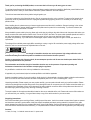
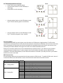
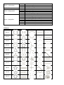
LASERSCAN 1000 3D V2
Exceptional 3D ILDA laser with 5 different effects in a single unit
M A N U A L
V E R S I O N
1 6 - 0 4 - 1 4
1 . 0
Due to continuous product development, please ensure that you have downloaded
the latest instruction manual for this product from the Kam website at www.kam.co.uk
For the latest instruction manual updates and information on the entire Kam range visit:
www.kam.co.uk
Kam products are manufactured by: Lamba plc, Unit 1, Southfields Road, Dunstable, Bedfordshire, United Kingdom LU6 3EJ
Telephone: (+44) (0)1582 690600 • Fax: (+44) (0)1582 690400 • Email: [email protected] • Web: www.lambaplc.com
If this product is ever no longer functional please take it to a recycling plant for environmentally friendly disposal.
Due to continuous product development, specifications and appearance are subject to change.
© Copyright Lamba plc 2014. E&OE.
Thank you for purchasing this KAM product, we are sure that it will serve you for many years to come.
To optimise the performance of this product, please read these operating instructions carefully to familiarise yourself with the basic
operations of this unit. After you have read the instructions, please retain them for future reference.
This unit has been tested at the factory before being shipped to you.
To prevent or reduce the risk of electrical shock or fire, do not expose the unit to rain or moisture. To prevent a fire hazard, do not
expose the unit to any naked flame sources. Unplug this apparatus during lightning storms or if it is unlikely to be used for long
periods of time.
When installing the unit, please ensure you leave enough space around the unit for ventilation. Slots and openings in the unit are
provided for ventilation to ensure reliable operation of the product and to protect it from overheating. To prevent fire hazard, the
openings should never be blocked or covered.
Always handle the power cable by the plug. Never pull out the plug by pulling on the cable. Never touch the power cable when your
hands are wet as this could cause an electric shock. Do not tie a knot in the cable. The power cable should be placed such that it is
not likely to be stepped on. A damaged power cable can cause a fire or give you an electrical shock. Check
the power cord periodicaly, if you ever find that it is damaged, replace it before using the unit again. Contact your retailer for a
replacement.
The voltage of the available power supply differs according to country or region. Be sure that the power supply voltage of the area
where this unit is to be used meets the required written on the unit.
The lightning flash symbol inside a triangle is intended to alert the user to the presence high voltage within the unit’s
enclosure that may be of sufficient power to constitute a risk of electrical shock to persons.
Caution: to prevent the risk of electric shock, do not attempt to open the unit. No user-serviceable parts inside. Refer all
servicing to qualified service personnel.
The exclamation mark inside a triangle is intended to alert the user to the presence of important operating and
maintenance instructions in the literature accompanying the appliance.
Any modification carried out on the unit may invalidate the unit’s warranty.
If applicable, only use the stand, tripod or bracket specified or sold with the apparatus.
Select the installation location of your unit carefully. Avoid placing it in direct sunlight or locations subject to vibration and excessive
dust. Do not use the unit where there are extremes in temperature (below 41ºF / 5ºC or exceeding 95ºF / 35ºC).
Unpacking and safety: Please unpack your new product carefully, your new product should reach you in perfect condition. Please
check that no damage has occurred during transit. If any damage is found, do not operate your unit. Please contact the retailer you
purchased it from immediately. If there is any damage to the mains cable do not use the device. Always disconnect the unit from
the mains supply when carrying out any servicing or cleaning of the unit.
The serial number for this equipment should be located on the rear or underside of the unit. Please make a note of this number as
you will need it for your warranty, it is a good idea to keep a copy of the serial number for your own records.
Unpacking instructions
CAUTION! Immediately upon receiving a fixture, carefully unpack the carton, check the contents to ensure that all parts are present
and have been received in good condition. Notify the shipper immediately and retain packing material for inspection if any parts
appear damage from shipping or the package itself shows signs of mishandling. Save the package and all packing materials. In the
event that a fixture must be returned to the factory, it is important that the fixture be returned in the original factory box and packing.
Contents
1 x laser, 2 x keys, 1 x interlock connector and 1 x power cord.
Power Supply
Cable (EU)
Brown
Light Blue
Cable (US)
Black
White
Pin
Live
Neutral
Yellow/Green
Green
Earth
International
L
N
DMX-512 connection between fixtures
The fixture is equipped with 3-pin XLR sockets for DMX input and output. The sockets are wired in parallel. Only use a shielded
twisted-pair cable designed for 3-pin XLR-plugs and connectors in order to connect the controller with the fixture or one fixture with
another.
XLR-connection
Building a serial DMX-chain
•
•
•
•
•
If you are using a standard DMX-controller, you can connect the DMX-output of the controller directly with the DMX-input of
the first fixture in the DMX-chain. If you wish to connect DMX-controllers with other XLR-outputs, you need to use adapter
cables. (DMX controller not supplied).
Connect the DMX-output of the first fixture in the DMX-chain with the DMX-input of the next fixture. Always connect output
with the input of the next fixture until all fixtures are connected.
If you use a controller with 5 pins DMX connector, you need to use a 5 to 3 pins adapter.
The DMX output and input connectors are pass-through to maintain the DMX circuit, when power is disconnected to the unit.
Each fixture needs to have a DMX address to receive the data from the controller. The DMX address number which could be
read from rear panel of each fixture is between 000~511.
Proper laser set up & usage
This fixture has been designed to be hung. It is recommended for safety purposes, your lighting effect are properly mounted using
a suitable hanging clamp and safety cable. Items appropriate for safe and effective mounting are easily sourced from your lighting
vendor.
International laser safety regulations require that lasers must be operated in the fashion illustrated below, with a minimum of 3
meters (9.8 ft) of vertical separation between the floor and the lowest laser light vertically. Additionally, 2.5 meters of horizontal
separation is required between laser light and audience or other public spaces.
2
3
Front Panel
1. Laser output – Laser output aperture
2. Power – Red LED is ON
3. Music – Synchronise to detected music signal
1
Rear Panel
11
13
9
12
6
10
8
4.
5.
6.
7.
8.
9.
Switch – Power on and off
Mains input with intergrated fuse holder
DMX input - 3 PIN Male XLR
DMX output – 3 PIN Female XLR
ILDA input – Standard ILDA DB25 input
ILDA through – Standard ILDA DB25 output
14
7
10.
11.
12.
13.
14.
4
5
Cooling fan – Never cover the fan
Safety eye – Attach the safety cable
LED function displaY
Safety switch – turns unit off immediately
Key switch
Operating Mode
When the laser is powered on, the LCD monitor on rear panel shows the current operating standalone mode, DMX address or
Slave mode. With help of the LCD control panel, it is very easy to set and change the operating mode of the laser. The next time
the laser is powered on it will show the last setting used before the laser was powered off.
Mode Option, to choose the operating mode of laser.
Confirmation, to confirm the selected mode.
UP/DOWN, to change operating mode, parameter or DMX address.
Operation
Display
AuT
A3d
AuB
AuL
AuN
Auo
S3d
Sob
SoL
SoN
Soo
Stand alone mode pre-programmed effect
Automatically cycle through its built in programs. This mode will only show the “in air” effects.
Automatically cycle through the built-in 3D effects
Automatically cycle through the built-in traditional beam effects.
Automatically cycle through the built-in northern lights effects.
Automatically cycle through the built-in gratings effects.
Automatically cycle through the built-in 3D universe effects.
Cycle through the built-in 3D effects by sound activation
Cycle through the built-in traditional beam effects by sound activation
Cycle through the built-in northern lights effects by sound activation
Cycle through the built-in gratings effects by sound activation
Cycle through the built-in 3D universe effects by sound activation
SOUND ACTIVATION MODE
Sound sensitivity
The laser has a built in microphone and to reduce and increase the sensitivity of the pick up, which will alter the reaction of the
programs, use the Sound activation mode settings.
•
•
•
Press FUNC till you see S6
Press UP/DOWN to set the microphone sensitivity. S 0 is no sound activation, from S 1 to S 9; the sensitivity level will
increase and be more sensitive.
Press Enter to confirm.
ATTENTION! In pre-programmed standalone MUSIC SHOW mode, the laser beam will black-out in 3 seconds without AUDIO/MIC
activated signal.
DMX MODE
• Press FUNC to enter the MODE selection
• The LED panel will show 001 for DMX mode
• Press ENTER to confirm the setting
Now the laser is working in DMX mode.
Use the up/down buttons to select the DMX address.
Note: In DMX MODE, once the DMX cable is connected to the laser and DMX controller, the DMX LED in front panel of laser will
be ON.
Controlling units via DMX - each unit uses 19 DMX channels
To set the DMX address
1. Press the function button until *** is displayed (range 001-512)
2. Using the up / down buttons select the desired DMX starting address
3. Press the enter button to confirm
4. Continue this formula to address any additional units
Note on setting the DMX address of units - If one or several units are to be controlled at the same time with the same features, set
all units DMX address to the same value
Example all units to 001
If individual control of several units is required, each unit must have its on unique address and no channels must cross
Example unit 1 set to 001 – unit 2 to 020 etc adding 19 clear channels each time
Master slaving units with no DMX controller
Set the master unit to the desired setting
Example: auto or sound
Set all other units to slave mode
To set slave mode press the function button until SLA is displayed then press the enter button to confirm
Only one unit must be set as a master and all other units must be set as slave
Connect each unit together via a 3pin DMX lead
PATTERN MIRROR REVERSE SETTING
• Press FUNC to enter the MODE selection
• Use the up/down buttons to set the LED display to
match Fig A.
• Press ENTER to confirm the setting.
FIG. A
FIG. B
•
Using the up/down buttons, set the LED display to match
Fig. B. This will rotate the graphic in the X direction.
FIG. C
•
Using the up/down buttons, set the LED display to match
Fig. C. This will flip the graphic in the Y direction.
ILDA Control Mode
This unit has the ILDA DB25 port which allows control of the laser via a PC/Mac laser or lighting software. The PC must be
connected to an interface and then the ILDA cable from the interface is connected to the ILDA input socket on the rear of the laser.
When connecting the ILDA plug to the laser this will override all built in standalone functions of the laser, and can then only be
controlled by the PC/Mac software. Removing the ILDA cable will re-enable all standalone functions.
Please note: it should be possible for any ILDA controlled software to operate this laser, if your software is having problems
controlling the laser this maybe down to a cable connection issue. Some interfaces and cables may have different wiring
configuration. The fourth and seventeenth pin of the ILDA socket need to be connected. If you rectify this issue on your interface
then this will cure the control issue.
DMX Channels Chart
Several operating modes were pre-programmed into this laser projector on DMX channel 1. To enable full DMX control, channel 1
must be set to DMX control mode and have a value of 250-255 this will enable the rest of the DMX channels.
DMX channels chart when ILDA is connected
Channel
Value
000-004
005-127
CH 1 – Grating rotation
128-133
134-255
000-031
032-063
064-095
096-127
CH2 – Grating effect
128-159
160-191
192-223
224-255
Function
No grating rotating
Clockwise grating rotating
No grating rotating
Anticlockwise grating rotating
Laser 3D Effect
Scanned Beam Effect (Pattern Effect)
Laser Lumina Effect
Scanned Beam Effect (Pattern Effect)
Burst Grating Effect
Scanned Beam Effect (Pattern Effect)
Laser Universal Effect
Scanned Beam Effect (Pattern Effect)
DMX channels chart when ILDA is NOT connected
Channel
Value
Function
000-018
Laser OFF
019-036
AUT Auto Show with Mixed 5 effect
037-054
A3D Laser 3D Effect Auto Show
055-072
AUB Scanned Beam Effect Auto Show
073-090
AUL Laser Lumina Effect Auto Show
091-108
AUN Burst Grating Effect Auto Show
109-126
AUO Laser Universal Effect Auto Show
CH 1 – Mode
127-144
SOU Sound Show with Mixed 5 Effect
145-162
S3D Sound show with LASER 3D
163-180
SOB Sound show with Scanned Beam
181-198
SOL Sound show with LASER LUMIA
199-216
SON Sound show with Burst Grating
217-234
SOO Sound show with Laser Universal
235-255
DMX MODE
000-051
1 Group Patterns.
052-103
2 Group Patterns.
CH 2 - Group
104-155
3 Group Patterns.
156-207
4 Group Patterns.
208-255
5 Group Patterns.
CH 3 - Pattern
000-255
Every 16 for 1 Group, total 16 patterns.
000-007
Original
008-015
Red
016-023
Green
024-031
Yellow
032-039
Blue
040-047
Purple
CH 4 - Colour
048-055
Light Blue
056-063
White
064-111
Colour Rolling
112-159
Colour Jumping
160-127
Colour Moving
208-255
Strobing
000
Full pattern without clipping
CH 5 - Clipping
001-127
0%~99% fixed pattern clipped
128-255
Clipping Speed
000-127
100%-5% fixed pattern zoomed
128-169
Zooming IN
CH 6 - Zooming
170-209
Zooming OUT
210-255
Alternately Zooming
CH 7 – Zoom speed
000-255
Fast to Slow
000-127
0 -359 degree fixed Y axis rolled
CH 8 – Y Axis rolling
128-191
Clockwise rolling
192-255
Anticlockwise rolling
CH 9 – Roll speed
0-255
Fast to Slow
000-127
0 -359 degree fixed X axis rolled
CH 10 – X Axis rolling
128-191
Clockwise rolling
192-255
Anticlockwise rolling
CH 11 – Roll speed
0-255
Fast to Slow
000-127
0 -359 degree fixed Z axis rolled
CH 12 – Z Axis Rolling
128-191
Clockwise rolling
192-255
Anticlockwise rolling
CH 13 – Roll speed
0-255
Fast to Slow
000-127
128 different fixed position on X axis
CH 14 – Y Axis moving
128-191
Clockwise moving
192-255
Anticlockwise moving
CH 15 – Move speed
0-255
Fast to Slow
000-127
128-191
192-255
0-255
000-004
005-127
128-133
134-255
000-031
032-063
064-095
096-127
128-159
160-191
192-223
224-255
CH 16 – X Axis moving
CH 17 – Move speed
CH 18 – Grating rotation
CH 19 – Grating effect
Pattern list
DMX
000-015
016-031
032-047
048-063
064-079
080-095
096-111
112-127
128-143
144-159
160-175
1
2
128 different fixed position on Y axis
Clockwise moving
Anticlockwise moving
Fast to Slow
No grating rotating
Clockwise grating rotating
No grating rotating
Anticlockwise grating rotating
Laser 3D Effect
Scanned Beam Effect (Pattern Effect)
Laser Lumina Effect
Scanned Beam Effect (Pattern Effect)
Burst Grating Effect
Scanned Beam Effect (Pattern Effect)
Laser Universal Effect
Scanned Beam Effect (Pattern Effect)
3
4
5
176-191
192-207
208-223
224-239
240-255
The Kam LaserScan 1000 3D laser projector offers 5 different effects in one package. The unit has been classified as a
Class 4 laser product (please refer to the KAM Class 4 Laser Product Guide for details of what this means) because it is
capable of emitting high power laser beams that can cause eye damage. However, each of the 5 effects has a different
hazard associated with it. It is the purpose of this guide to outline what these hazards are. The table below outlines all
the effects and usage mode with an indication of the hazard potential for each.
EFFECT
MENU
POTENTIAL
HYPER 3D EFFECT
NO
DESCRIPTION
HAZARD
1
3D PROJECTION
3B
2
NORTHERN LIGHTS
3R
AUTO
3
MULTI GRATINGS
3B
4
KALEIDOSCOPE
3B
5
FLAT BEAM & IN AIR TUNNEL
4
1
3D PROJECTION
3B
2
NORTHERN LIGHTS
3R
SOUND
TO
3
MULTI GRATINGS
3B
LIGHT
4
KALEIDOSCOPE
3B
5
FLAT BEAM & IN AIR TUNNEL
4
MODE
SAFE DISTANCE OF
USAGE
15m
0.5m
25m
140m
270m
15m
0.5m
25m
140m
270m
MODE: This is either AUTO where each selected effect varies randomly or SOUND TO LIGHT where the selected effect
changes in time to the beat of the music.
EFFECT NO: This is the allocated number for the specific effect.
3D EFFECT: This is the name of the specific effect.
MENU DESCRIPTION: This is the symbol that appears on the LED display on the back of the unit.
POTENTIAL HAZARD: This the hazard presented by the effect. It is based on the product classification system and
uses the following classes:
3R - can be considered safe.
3B - is hazardous and must be used with caution.
4 - is extremely hazardous and must be used with the utmost of caution.
Note: A single beam can cause tissue burns a distances up to several metres!
SAFE DISTANCE OF USAGE: This is the distance below which the effect can become hazardous when shone directly
into the audience eyes. Use this effect beyond the distance shown.
These figures have been arrived at by measuring the smallest beam shape that the unit can project for each effect –
these represent its most concentrated beam power and thus its greatest hazard. These figures are to be used as a
guide to help determine what kind of show one can carry out. Effects like the Wide Angle Starcluster (effect 7) can be
safely directed into an audience and can look very spectacular. The Northern Lights (effect 3), even though it is safe, is
more effective when projected onto a wall. Please also note that the settings Aut and Sou (Automatic Random and
Sound to Light) must never be used for audience scanning as you have no control over which effect will be used! If
unsure about a show, always project at least 3m above audience head height. This is particularly true for the effects 1
and 8 as the 3m rule applies to the lowest part of the scanned image that can fall onto an audience. For the effects 2, 4,
5 and 6 the 3m rule applies for the central part of the projection – the very edges of the display are reduced in power
and can fall onto audience. Scan an audience, at the edges, with these effects at your discretion.
When using this unit in DMX mode it is important to understand that this will override all internal effects and all the
moving effects can be stopped to produce single beams. For this reason it is vital to ensure that no beams can go into
audience at distances less than those specified in the table above.
The same applies for the unit being used in ILDA mode – all the internally programmed images are overridden. Any
audience scanning must be with the fastest possible scan rate and largest possible images at distances determined by
careful calculation. If in any doubt – don’t audience scan.
Please refer to the Kam Class 4 Laser Product Guide for more detailed information.
Specifications
Mains Input
Fuse
Total Power
X/Y Axis Beam Angle
Music Control
Laser Power
Laser Classification
Laser Safety Standard
Condition Temperature
DMX Connections
DMX Channels
Measurements
Nett Weight
AC100~240V, 50/60Hz
250V /1.6A Slow Blow (20mm Glass)
48w
±20°
Audio / Sound Activated
150mW 638nm red laser
100mW 532nm green laser
500mW 450nm blue laser
Class 4
EN60825-1 2007
10~40°
3 pins XLR male/female
Max 19 channels
290 x 190 x 245mm
4.2Kg