1
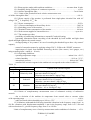
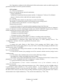
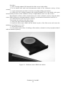
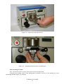
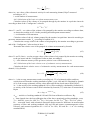
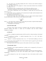
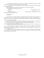
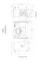
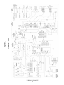
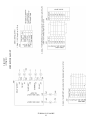
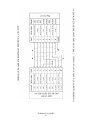
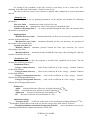
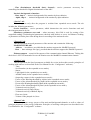
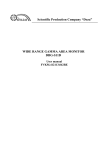
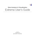
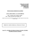
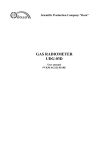
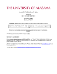
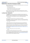
Scientific Production Company “Doza” UDA-1AB: RADIOACTIVE AEROSOL MONITOR User Manual FVKM.412123.002RE Cont ent 1 Description and operation of the product ……………………………...…… 1.1 Product functionality ……………………………………………...….… 1.2 Technical characteristics …………………………………………..…… 1.3 Configuration …………………………………………………….….…. 1.4 Design and operation …………....……………………….…………….. 1.5 Marking and sealing …………………...……………………………….. 1.6 Packing …………………………………………………………………. 2 Intended use ……………………………………………………………...… 2.1 Operational limitations ……………………………..………………...… 2.2 Preparation of the product for use ..……………….…..……………...… 2.3 Use of a product …….….….…………………………….……...……… 2.4 Adjustment ………………………………………………………..….… 3 Maintenance ………………………………………………………………... 3.1 General notes ……………………………………………………..….… 3.2 Safety precautions ……………………………………………………… 3.3 Maintenance routine ………………………………………………....… 4 Calibration routine ………………………….………………….…………... 4.1 General requirements ………………………………….……..………… 4.2 Preliminary arrangements …………………………………………....… 4.3 Safety precautions ……………………………………………………… 4.4 Conditions …….……….………….……………………….………….... 4.5 Procedure ………………………….……………….………………..…. 4.6 Processing of results ……………………………………………..…..… 5 Routine repairs …………………………………………….……………..… 6 Storage ……………………………………………………….…….…….… 7 Transportation ……………………………………………...…………….… 8 Disposal ………………………………………………………………….… 3 3 3 5 5 8 8 8 8 8 9 9 10 10 10 10 13 13 13 14 14 15 17 19 19 19 20 Appendix A Outline drawing ……………...…………………………..…….… Appendix B Wiring diagram ……………………...…………….………...…… Appendix C Connection layout …………………………...…………………… Appendix D List of parameters accessible for displaying and editing using the “Configurator” Software …………………………………………..… 21 22 23 FVKM.412123.002RE 2 26 This user manual contains information on design, principle of operation, characteristics of the product and instructions essential for correct and safe use of this product (intended use, maintenance, servicing, storage and transportation), as well as information regarding the utilization of the product. 1 DESCRIPTION AND OPERATION OF THE PRODUCT 1.1 Product functionality UDA-1AB: radioactive aerosol monitor FVKM.412123.002 (hereinafter – monitor) is intended for: - continuous measurements of volumetric activity of radioactive aerosols containing artificial alpha- and beta-emitting nuclides; - indication of effective equivalent concentration (EEC) of 222Rn in the indoor air; The monitor is used for monitoring of radioactive emissions at nuclear power plants and nuclear facilities and on nuclear-powered vessels. The monitor is able to transfer data to communication channels and provides access to the processed information via communication lines based on Ethernet IEEE 802.3 interface (TCP/IP communications protocol) or two channels RS-485 interface (ModBUS communication protocol), RS-232 and can be operated both on off-line mode and as a component of radiation monitoring systems, complexes and installations. The monitor is able to work in conjunction with pump unit BN-01 FVKM.064424.002 or with other external pump unit; it maintains operability when used in combination with the noble gas monitor UDG-1B FVKM.412123.001 under conditions of sharing common pump unit BN-01. The monitor is able to control actuators (pumps, valves etc.) by switching the voltage 220 V, 50 Hz. The monitor can be installed in a stationary position or can be used as a portable measurement instrument. 1.2 Technical characteristics 1.2.1 Energy range of alpha radiation …….…..…..….…….…..…….…..….. 3000 to 9000 keV. 1.2.2 Energy range of beta radiation …….…..…..…….…….…..…….……….. 50 to 3000 keV. 1.2.3 Measurement range of volumetric activity of radioactive aerosols with artificial: - alpha-emitting nuclides ..…………....…......….........………..…..… 1.010-2 to 2.0105 Bq/m3 ; - and beta-emitting nuclides ..…………....……….….…………....… 1.010-1 to 1.0106 Bq/m3. 1.2.4 Indication of the effective equivalent concentration 222 of Rn in the range …………………...….……...……………………..….……. 1.0 to 2.0105 Bq/m3. 1.2.5 Sensitivity to particles with energies within the detectable range: - alpha radiation (by 239Pu) ..………….…………..….…….……….…....... not more than 0.02; - beta radiation (by 90Sr (90Y)) .……….…………..….…….………...…..... not more than 0.01. 1.2.6 Limits of the permissible basic relative measurement error: 1) volumetric activity of radioactive aerosols related to artificial alpha-emitting nuclides: - in the range 1.010-2 to 1.0 Bq/m3 …….…….…….……….…….….……..……..…… 50 %, - in the range 1.0 to 1.0 Bq/m3 …….……...….………………...….….…….….…….… 20 %; 2) volumetric activity of radioactive aerosols related to artificial alpha-emitting nuclides: - in the range 1.010-1 to 10 Bq/m3 …….……...….…..……….…..…..…….…….……. 50 %, - in the range 10 to 1.0 106 Bq/m3 …….…….…….……………...…..….………..……. 20 %. 1.2.7 Intrinsic background of the monitor is less than: - alpha-channel ………………..………….………….……..…..……..……….. 1.010-2 Bq/m3 ; - beta-channel ………………………………………………….…...….………. 1.010-1 Bq/m3. FVKM.412123.002RE 3 1.2.8 Warm-up time under stable ambient conditions ...….…….……….. not more than 10 min. 1.2.9 Instability during 24 hours of continuous operation ..………..…….……………… 15 %. 1.2.10 Airflow through the filter .…………..…………...……………...…...…….. 5 to 60 l/min. 1.2.11 Limits of the permissible basic relative measurement error of airflow through the filter ……..……………..….…………..….………………..….……...… 10 %. 1.2.12 Power supply of the monitor is performed from single-phase electrical line with AC 2 , 5 voltage 220 22 33 V, frequency 50 2 ,5 Hz. 1.2.13 Power consumption …………………………..…..……………………..….……. 50 VA. 1.2.13.1 Power consumption with auxiliary device .……….….....………..…...………. 300 VA. 1.2.14 Switching power of the monitor ............…..……..…........…..………..….….…. 225 VA. 1.2.15 Nominal current consumption of the monitor .......…...…...….......................….. 100 mA. 1.2.16 Peak current supplied to external devices ...……….….………..………….….. up to 4 A. 1.2.17 The monitor provides: - possibility of transferring information to external PC and self-testing; - generating information about exceeding of the threshold by local audible and light alarm signals and light signal to the central control; - closing/opening of “dry contact” in case of exceeding the threshold (up to three “dry contact” outputs); - control of external actuators by applying voltage 220 V, 50 Hz to the “PUMP” connector. - input/output of signal from standard measuring devices (flow meters, level gauges, etc.) using an analog input / output (4 – 20 mA). 1.2.18 Operating conditions: - operating temperature range ……………………………………..……… minus 10 to +50 °C; - relative humidity …………..………………..………..……………..…..…… 98 % at +35 C; - atmospheric pressure ………………………………….…………..…….… 84.0 to 106.7 kPa; - content of the corrosive agents in the ambient air corresponds to the values in table 1.1. Table 1.1 Type of atmosphere Content of the corrosive agents Designation Description Sulfur dioxide gas no more than 20 mg/(m2·day) (not more than 0.025 mg/m3); I Relatively clean Chlorides not more than 0.3 mg/(m2·day) Sulfur dioxide gas no more than 20 to 250 mg/(m2·day) II Industrial (not more than 0.025 to 0.31 mg/m3); Chlorides - not more than 0.3 mg/(m2·day) Sulfur dioxide gas not more than 20 mg/(m2·day) (not more than 0.025 mg/m3); III Maritime Chlorides – 0.3 to 300 mg/(m2·day). 1.2.19 Limits of complementary measurement error of volumetric activity of radioactive aerosols: - due to deviation of the ambient air temperature from normal value to extreme values of the operating range ………………………...…………………….………………...………..… ±10 %; - under increased relative humidity up to 98% at +35C ……………….…..………….. ±10 %. 1.2.20 Monitors withstand the following sinusoidal vibrations in the frequency range from 1 to 120 Hz: vibrations with displacement amplitude 1 mm in the frequency range from 1 to 13 Hz and with acceleration of 1 g in the frequency range from 13 to 120 Hz. Limits of complementary error of activity measurement under conditions of vibration …. 5 %. FVKM.412123.002RE 4 1.2.21 Monitor are stable against seismic impacts with magnitude 9 according to the MSK-64 scale, being installed on the building structures of the industrial site at 70 to 30 m relative to the grade level. After the seismic impact with the above mentioned parameters monitor are operable within the limits stated in sections 1.2.6, 1.2.17, during the whole life cycle under specified operation conditions. 1.2.22 Monitors withstand the impact of the incident plane (P) and air shock wave (AV). 1.2.23 Degree of protection provided by casings against ingress of solid items and water - IP65. 1.2.24 Monitor maintain operability under conditions of background gamma radiation with the ambient equivalent dose rate not more than 0.01 mSv·h-1, at that limits of complementary measurement error are 50 % within the whole measurement range of the volumetric activity. 1.2.25 Monitor withstand the electromagnetic interference of the 3 grade according to IEC 1000-4-8-93, IEC 1000-4-9-93, IEC 61000-4-2-95, IEC 61000-4-3:2006, IEC 61000-4-4:2004, IEC 61000-4-5-95, IEC 61000-4-6-96, IEC 61000-4-11:2004, IEC 61000-4-12-95, IEC 61000-4-13:2002, IEC 61000-4-14-99, IEC 61000-4-28-99. 1.2.26 Monitor comply with the standards for emission set forth by IEC 61000-3-2:2005, IEC 61000-3-3:2008 and CISPR 22:2006 for class A equipment. 1.2.27 By its protection against electric shock monitor comply with the IEC 61010-1:2001. 1.2.28 Monitor are fire-safe products with fire probability of no more than 10-6 year-1. 1.2.29 Structure, materials and coatings of monitors withstand the exposure to water decontaminating solutions: - paint coatings: № 1 caustic soda (NaOH) – 50 g/L, potassium permanganate (KMnO4) – 5 g/L; - units and blocks of stainless steel and glass: № 2 - oxalic acid (H2C2O4) – 10 ÷ 30 g/L, nitric acid (НNО3) – 1 g/L; - connectors and contacts: № 3 - 5 % citric acid solution in ethanol С2Н5ОН (density 96 %). 1.2.30 Overall dimensions of the monitor …….………..….....……….….… 396260302 mm. 1.2.31 Weight ………….……….….……………….….……….……………….……… 15.6 kg. 1.2.32 Mean time before failure …………………….………………. not less than 25000 hours. 1.2.33 Mean life time ………………………………….….…………..…. not less than 10 years. 1.3 Configuration 1.3.1 The monitor is a complete unit, both functionally and structurally. The following items come with the monitor: - check source placed in the holder and intended for testing of operability of the monitor; - coil of the filter used for winding of the tape filter during its replacement; - “Configurator” software intended for current control of the monitor, calibration and, when necessary, adjustment of the monitor from PC (hereinafter - “Configurator” software); - cable for connection to PC using “RS-232” connector; - power cord; - consumables, installation kits, spare parts and accessories. 1.4 Design and operation 1.4.1 Measuring low activity and achieving low limit of detection requires concentration of aerosols in a small volume. With this purpose the air is pumped through the filter. Air enters from the place to be tested (workplace or ventilation system) through the inlet pipe located at the top of the front protective panel and passes through the 50 mm wide working area of the filter tape. Then through a perforated measuring table (board) where a filter is located air is fed to the vortex flow meter and through the outlet pipe to the pump. The monitor measures airflow rate and the pumped air volume. Detector and collimator are placed above working area of the filter. FVKM.412123.002RE 5 Alpha and beta particles emitted by nuclides attached to aerosol particles when passing through a detector produce electrical pulses. Pulse amplitudes are proportional to the energy of alpha particles. Signal from preamplifier is transferred to one of the inputs of the two-way 1024 channels analogdigital converter (ADC). Thus the data related to energy spectrum of alpha particles emitted by nuclides on the filter can be obtained. Calculation of volumetric activity of artificial beta-emitting radionuclides is performed on the basis of total number of counts in the energy range corresponding to detection of beta radiation. Indication of volumetric activity of 222Rn is calculated from the alpha radiation data for 222Rn daughter products (218Po, 214Pb). Detection of beta-emitting 222Rn daughters (214Bi, 214Po) is carried out as a total along with artificial beta-emitting radionuclides (Figure 1.1). For compensation of external background additional measuring channel is provided in the monitor; detector of this additional measuring channel is shielded from external background radiation. The background channel is connected to the second input of the ADC. Background channel readings are subtracted during the calculations of the results. The monitor can be operated in combination with the pump unit BN-01 or external sampling devices. Monitored parameters are flow rate and pressure drop (pressure differential) on the filter. When using pumps producing low suction pressure (for example, centrifugal pumps) the flow rate decreases as the filter is getting loaded with aerosols. On the other hand, when using pumps with suction pressure (for example, sliding vane rotary pumps) there is no decrease of the flow rate but pressure drop on the filter increases. To ensure timely change of filter when it is dust-loaded, the minimum acceptable volume flow rate and maximum acceptable pressure drop are set. When the flow rate falls below minimum allowable level or the pressure drop on the filter exceeds corresponding maximum allowable level then the monitor feeds the tape exposing next window of the filter. Setting of the limiting values is performed by means of “Configurator” software taking into account specific operating conditions. It is recommended to set the minimum pumping rate to a value which is 10 l/min less than the initial value (i.e. with a clean filter), and pressure to a value which is 1500 to 2000 Pa greater than the initial one. 1.4.2 Obtained spectral, flow rate and air volume data are processed by the monitor’s processor. During processing the energy spectrum is divided into several energy intervals (regions of interest): region of alpha-emitting 222Rn (and 220Rn-thoron) decay products, region of artificial alpha-emitters and region of beta-emitters, see Figure 1.1. Figur e 1.1 – Measured energy spectrum of working area of the filter after pumping Design of the monitor allows measuring activity on the filter of the alpha-emitting radon and thoron decay products and the total activity of alpha-emitting artificial radionuclides. The data on alpha-emitting radon and thoron decay products makes it possible to take into account the contribution of beta-emitting decay products and determine the activity of artificial beta-emitters. Calculated results are displayed on a liquid-crystal display (LCD). FVKM.412123.002RE 6 The obtained data are then compared with preset thresholds set by the user during adjustment of the monitor. If the first threshold is exceeded the yellow light indicator and audible alarm are switched on. If the second threshold is exceeded the red light indicator is switched on again accompanied by the audible alarm. The audible alarm can be switched off by pressing a button on the monitor. If threshold for alpha-emitting isotopes is exceeded, one or two “!” symbols appear on LCD in the line where alpha activity of aerosols is displayed, and for beta activity of aerosols symbol appears respectively in the line where volumetric activity of beta emitters is displayed. The alarm signals are also sent to a signalling device (SD) if it is connected. If an external device is connected to a “dry contact”, the monitor allows switching this device on/off when a threshold is exceeded. 1.4.3 Measured values are recorded into non-volatile memory forming the measurement archive; if necessary, these data can be readily retrieved using the “Configurator” software. The total memory capacity allows to store not less than 3000 measurement results. 1.4.4 The three data exchange interfaces of the monitor are: RS-232, RS-485 and Ethernet IEEE 802.3. The monitor can be supplied with interface RS-232 and Ethernet IEEE 802.3, or with RS-232 and RS-485. All installed interfaces can operate simultaneously. The view of the monitor’s panel with socket designations is shown in Figure 1.2. Figure 1.2 – External interface connectors RS-232 is a service interface designed for control, diagnostics, setup and maintenance of the monitor at the maximum detailed level. This interface is used by the “Configurator” software, supplied with the monitor. To prevent malfunctions of the monitor due to unqualified usage by untrained personnel, the “Configurator” software has a password-protected access restriction. This aim is also attained by the use of a closed protocol in this software. FVKM.412123.002RE 7 RS-485 and Ethernet IEEE 802.3 are external interfaces available for the user. These interfaces are meant for integrating the monitor into automated complexes and systems of radiological monitoring. 1.5 Marking and sealing 1.5.1 A nameplate with the following information is attached to the monitor housing: - trademark and name of the manufacturer; - reference designation of the monitor; - works number of the monitor according to the manufacturer numeration system; - sign of approval of the measurement instrument; - degree of ingress protection against solid items and water provided by casings; - made in Russia. 1.5.2 Method of marking and place on the monitor where it is made shall comply with the design documentation. 1.5.3 The monitor is sealed in accordance with the design documentation. 1.6 Packing 1.6.1 The monitor’s package complies with the design documentation and provides protection against ingress of atmospheric precipitations and aerosols, splashes of water, dust, sand, solar ultraviolet radiation and limits the ingress of water vapour and gases. 2 INTENDED USE 2.1 Operational limitations 2.1.1 The monitor maintains operability under conditions detailed in section 1.2. 2.1.2 For the monitor operation air pumping through the filter is necessary. A sampling device should comply with the following requirements: 1) suction should not exceed 20 kPa, maximum allowable pressure differential during blowings is 10 kPa; if blowings are carried out under pressure exceeding 10 kPa, cutoff of the monitor should be provided by means of the stop valve and blowing of the air line through the bypass; 2) for ensuring correct measurements it is necessary to include in the project damping means necessary during switching the sampling on/off, opening and closing of valves. It is necessary to install between the sampling (pumping) device and the monitor a receiver, a diaphragm, a filter, etc. to smooth the pressure pulsations during operation of sliding vane rotary and forevacuum pumps. Minimum volume of the receiver is 1/5 of the air volume pumped during 1 minute; 3) residual pressure should not be greater than 3 kPa; 4) air flow rate shall be in the range 20 to 60 l/min. 2.1.3 When an external sampling device is used it is recommended to control the pumping by means of the monitor itself using a normally-closed solenoid air valve actuated by 220 VA, 50 Hz, or to control the pumping device directly via “TO PUMP” connector. Under the direct control the pumping device power shall not exceed 225 VA. 2.1.4 The following is not allowed during operation: - use of the monitor at medium (6 – 35 kV) and high (above 35 kV) voltage electric substation; - use of the monitor as parts of high power electric installations; - connection of the monitor to the circuit of signal earth; - use of mobile phones within 10 meters of the monitor. FVKM.412123.002RE 8 2.2 Preparation of the product for use ATTENTION! DURING PREPARATION OF THE MONITOR FOR USE AND DURING OPERATION REQUIREMENTS OF THE SECTION 2.1 SHOULD BE STRICTLY FOLLOWED. FAILURE TO COMPLY WITH THESE REQUIREMENTS CAN RESULT IN INCORRECT OPERATION OF THE MONITOR AND, IN SOME CASES, CAN DAMAGE THE MONITOR. 2.2.1 Stand alone (off line) mode: 1) place the monitor to the working area; 2) connect the monitor and the sampling device using a cable and a hose FVKM.302645.006, for connection of the pump unit BN-01 to the air line of the monitor the user shall be guided by outline drawing in the Appendix A; 3) connect the monitor to AC mains 220 V (50 Hz); 4) turn the power switch on. 2.2.2 In line with automation systems and installations: 1) place the monitor to the working area; 2) connect the monitor and the sampling device using a cable and a hose; 3) connect the monitor to the information network via the “RS-485” or “Ethernet” connector; 4) connect the monitor to AC mains 220 V (50 Hz); 5) turn the power switch on. Wiring diagram and connection layout are presented in Appendices B and C. 2.3 Use of the product 2.3.1 After power-on the built-in software is loaded. The software data set (configuration and settings) is located in the non-volatile memory, so no additional preparation for operation is needed after loading. The software tests control unit of the tape transport mechanism and flow meter. This is performed by generating tape feed commands and switching on pump or opening the valve. After 10 seconds since the beginning of pumping the air flow rate is measured. If it is within the preset limits, the program acknowledges the system operability and switches to operating mode. Each time when the monitor is switched on or the software is restarted a new filter tape frame is set. 2.3.2 After the monitor is switched on, the current air flow rate and total air volume pumped through the filter is measured each 100 sec. The spectrum is processed by the ADC simultaneously. Time is determined using the system non-volatile real-time timer. (If air flow rate drops below the critical value due to the filter contamination, the exposed section of the tape is replaced by a new one). The remaining life recording feature is provided in the monitor. 2.3.3 The monitor is self-operative. The measurement results and the monitor component status are displayed on LCD and when the monitor is used in line with automation systems the results are sent to the information network. If the filter tape should be replaced the monitor displays corresponding message on LCD and sends the message to the information network at least 1 hour before end of the tape is reached. The measurement results are updated every 100 sec and logged in the archive. The archive capacity is 3000 measurement results. 2.4 Adjustment 2.4.1 Parameters of the monitor can be changed using the “Configurator” software. A list of parameters available for displaying and editing using the “Configurator” is presented in Appendix D. To change parameters, connect the monitor to PC using a communication cable. The cable is connected to RS-232 socket of the monitor and to a serial port connector on PC. FVKM.412123.002RE 9 2.4.2 “Configurator” software should be installed on PC in accordance with the “Configurator” Software User Manual FVKM.001005-07 34 01. 3 MAINTENANCE 3.1 General notes 3.1.1 Maintenance is performed with the purpose of ensuring correct and long-term operation of the monitor. 3.2 Safety precautions 3.2.1 Before beginning to work with the monitor familiarize yourself with this User Manual. 3.2.2 During all operations with the monitor it is necessary to follow occupational and radiation safety requirements of current safety instructions in the company (facility). 3.2.3 Technical personnel with basic computer skills and skills of working with radiometric equipment are permitted to perform maintenance of the monitor. 3.2.4 During operation of the unit special attention shall be paid to power cord condition – in this place dangerous voltage can be present. 3.2.5 All cable connections and disconnections should be performed with the power supply cut off. When using the monitor as part of measurement information complexes, systems and installations “hot” connection of cables is allowed (without switching the monitor off). At that connection should be provided of the protective ground to corresponding terminals at the monitor and the signal receiving monitor. ATTENTION! IT IS NECESSARY TO STRICTLY FOLLOW ALL REQUIREMENTS, DESCRIBED IN SECTION 2.1. FAILURE TO COMPLY WITH THESE REQUIREMENTS CAN RESULT IN INCORRECT OPERATION AND IN SOME CASES TO FAILURES OF THE MONITOR. 3.3 Maintenance routine 3.3.1 Maintenance of the unit is carried out during regular operation of the unit and includes timely replacement of filter tape, general inspection of the unit, cleaning from dust and contamination, performance testing using the check source. 3.3.2 Replacement of the filter tape ATTENTION! RECOMMENDED FILTER TAPE CONSUMPTION DURING NORMAL OPERATION OF THE MONITOR IS NOT MORE THAN 10 METERS PER MONTH. EXPECTED AVERAGE FILTER TAPE CONSUMPTION DURING OPERATION UNDER EMERGENCY IS 3 METERS PER DAY. Replacement of the filter tape is performed when message about the end of the filter tape appears on the LCD of the monitor or is transferred via the information network. Before replacement prepare the filter tape. For this purpose reel in 10 ÷ 12 meters of tape from the delivery kit. The tape should not go beyond side surfaces of the reel. Fix the tape on the reel as shown in the figure on the lid. To replace the tape perform the following steps: - switch the unit off; - remove the protective panel of the monitor using the screwdriver; - unscrew fixing screws of the feeding and receiving reels; - pull both reels off; - install empty reel to the receiving reel place; - install a prepared reel with a new filter in the place of the receiving reel; FVKM.412123.002RE 10 - pull the filter tape through the measuring table and guiding rollers as shown on the tape movement diagram on the inner surface of the protecting lid and in Figures 3.1 to 3.3; - re-install the lid. Figure 3.1 Figure 3.2 FVKM.412123.002RE 11 Figure 3.3 3.3.3 General visual inspection of the monitor General visual inspection of the monitor is performed for timely detection and elimination of factors which can influence adversely on performance and safety of the monitor. General visual inspection is performed each time the tape is replaced. During the general visual inspection the condition of cables and reliability of attachment are checked (in case of stationary installation). If required, LCD and other parts are shall be cleaned from dust and contamination. 3.3.4 Decontamination 3.3.4.1 Decontamination of external surfaces of the monitor is performed in accordance with current work schedule and procedures of the company (facility). The reel, detector lid and side surfaces of the detector shall be decontaminated regularly after removal of the used filter tape using solutions 1) and 2) as stated in the section 1.2.28. After treating the surface by cleaning cloth moisten with decontamination solution wipe surface by cleaning cloth moisten with distilled water then dry using filter paper. Perform decontamination before calibration and in case of elevation of the monitor’s background as follows: - remove front and upper panels of the monitor; - unscrew cable connector of the detector module; - unscrew four screws, which fastens the detector to the front panel; - pull the detector out; - pull the collimator from the detector; when doing that do not touch the working surface of detector; - install new collimator and fix it in place by slightly pressing on it; - assemble the monitor in the reverse order; - used collimator shall be decontaminated using solutions 1) and 2) in section 1.2.28. FVKM.412123.002RE 12 3.3.4.2 For decontamination of the cable terminal connectors, LCD and measuring use solution 3) in section 1.2.28. No additional treatment with distilled water and drying with filter paper are required. 3.3.4.3 If necessary LCD and/or other parts shall be cleaned from the dust and contaminations by means of clean cloth. Dry cleaning can be performed with any periodicity. 3.3.5 Determination of the check source activity Determination of the check source activity should be performed for testing the monitor’s operability after each replacement of the filter tape but at least once a month. For determination of the check source activity: - remove the filter tape from the measuring table; - install the check source into holder in place of the filter screen; - switch on the monitor; - wait for 40 minutes then take at least 10 readings of the monitor by alpha and beta channels separately; record the readings each minute; Not e - in check source measurement mode (without pumping) the measurement result is the volumetric activity which is numerically equal to the source activity. - calculate arithmetical average values of measured volumetric activities for alpha- and betachannels. After completing the measurements calculate the expected readings of the activity of alpha and beta emitting radionuclides of the check source at the moment of measurements (Bq/m3) 0.693t / T1/2 Acalc A0 e , (3.1) where A0 – is reading of the check source for alpha channel and beta channel (activity values of 210Po and 210Pb, respectively) from the previous calibration certificate, Bq/m3. t – time elapsed after the previous calibration, years, T1/2 = 22.26 years – half-life of the check source (210Pb). The monitor is considered passed the performance test on the results of the check source activity measurement if the condition (3.2) is true | A A calc 100 | 15 % A calc (3.2) Otherwise it is necessary to perform an additional calibration of the monitor. 4 CALIBRATION ROUTINE 4.1 General requirements 4.1.1 Calibration of the monitor is performed in accordance with IEC 61453:2007. 4.2 Preliminary arrangements 4.2.1 Operations that should be performed during calibration and required equipment are listed in the table 4.1. FVKM.412123.002RE 13 Table 4.1 – List of calibration operations Operation Calibration equipment and its characteristics Section External examination Testing Measurement of the intrinsic background Determination of basic relative measurement error of pumped air 4.5.1 4.5.2 4.5.3 Visually 4.5.4 Gas meter, type SGB G4-1, range 0.4 to 6 m3/h (6,7 to 100 l/min) with basic measurement error of air flow 1.5 %. Pump unit BN-01 or other pumping unit, providing air flow rate in the range 20 to 60 l/min. Hose for connecting the gas meter. PC and communication cable. “Configurator” software FVKM.001005-07 Determination of the basic relative measurement error of the air volumetric activity 4.5.5 Determining activity of the check source 4.5.6 Working standards of grade 2, types 1SO and 1P9 with activity 102 103 Bq. Spectrometric combined alpha-emission source of SKAI type: 210Po+210Pb(210Bi) - industrial standard of grade 2 with activity 102 103 Bq. Spectrometric combined alpha-emission source of SKAI type: 210Po+210Pb(210Bi) - industrial standard of grade 2 with activity 102 103 Bq. Not e - It is acceptable to use other calibration equipment with characteristics that ensures determination of metrological parameters with required precision. 4.3 Safety precautions 4.3.1 It is necessary to follow safety requirements described in section 3.2 and in documentation accompanying calibration tools and equipment. 4.4 Conditions 4.4.1 The following normal operating conditions shall be met during calibration: - air temperature ………………………………….………………………………. +(20 ±5) °C; - relative air humidity ……….………………………..….....….…...……...… from 30 to 80 %; - atmospheric pressure ………………………………..……….………….… 86.0 to 106.7 kPa; - natural radiation background ……………………..…………….… not more than 0.2 Sv·h-1 ; - AC mains voltage …………………………………..…....….…..….…….…..… (220 ±4.4) V; - AC mains frequency ………………………………...…….…...…..…...………. (50 ±0.5) Hz; - harmonic factor ………….….…….………….…...…..…….….…….………….….….. ±5 %. 4.4.2 To perform the calibration, place the monitor in conditions specified in section 4.4.1. Plug in the monitor to the mains 220 V (50 Hz), connect PC to the monitor using the communication cable, and run “Configurator” software. If the calibration is performed without software, just arrange the monitor and connect it to mains 220 V (50 Hz). 4.4.3 Before switching the monitor on and performing the calibration keep it in conditions specified in 4.4.1 for 4 hours. FVKM.412123.002RE 14 4.4.4 Operations conducted with calibration facilities and monitor under test shall comply with guidelines detailed in relevant operation manuals. 4.5 Procedure 4.5.1 External examination Items to be checked during external examination: - proper completeness; - availability of operational documentation and the “Configurator” Software User Manual; - absence of defects which could affect the monitor operation. 4.5.2 Testing For testing switch the monitor on and observe results of self-testing. The monitor is considered operable if self-testing was successfully passed. 4.5.3 Measurement of the monitor’s intrinsic background Measurement procedure: 1) prepare the monitor for operation without pumping using clean filter tape; 2) switch the monitor on and in 40 minutes take and record measurement results of volumetric activity. If software is used for obtaining the results press «DATA UPDATE» button on the software toolbar, and then the measured values will be displayed in the area “Measurement”: - “Volumetric activity Alpha, Bq/m3”, - “Volumetric activity Beta, Bq/m3”, - “Volumetric activity of radon, Bq/m3”; 3) repeat the measurement procedure 2) 10 times, recording results each minute. 4.5.4 Determination of basic relative measurement error of the pumped air volume Determination is performed using pump unit BN-01 (or other pumping device). The “Configurator” software is used for registration of measured values. Procedure: 1) connect the outlet fitting to inlet fitting of the pumping unit BN-01 using a hose FVKM.302645.006 from the pump unit kit, use power cable to connect the pumping unit BN-01 to the monitor power outlet “TO PUMP”; 2) connect the inlet fitting of the monitor to an outlet fitting of gas meter using a connecting hose of relevant diameter; 3) switch on the monitor (the pumping unit will be actuated with the monitor) and gas meter simultaneously; 4) in 20 minutes take simultaneously and record the following readings: - the pumped air volume according to gas meter reading, - the volume of air pumped through by the monitor. It is displayed in the field “Volume of the pumped air, l” of the “Pumping” tab in the “Configurator” software window; 5) repeat procedure 4) 5 times each 20 minutes. 4.5.5 Determination of basic relative measurement error of the volumetric activity of radioactive aerosols Determination of basic relative measurement error of the volumetric activity of alpha emitters is performed by alpha radiation of 239Pu; of beta emitters – by beta radiation of 90Sr(90Y), using working standards of grade 2, type 1SO and 1P9 (hereinafter – working standards). It is allowed to use the SKAI check source in the rank of the working standards of grade 2 and determine basic relative measurement error of alpha radiation by 210Po, and for beta radiation by 210Pb(210Bi). FVKM.412123.002RE 15 Procedure: 1) place working standard 1SO instead of the filter screen in the holder; 2) in 40 minutes take and record measurement results of the volumetric activity of beta emitters; 3) repeat measurement procedure 2) 10 times recording readings each minute; 4) replace the 1SO working standard with working standard 1P9 in the holder and repeat measurement procedures of the volumetric activity of alpha emitters same as 2) and 3) above. Determination of basic relative measurement error of the volumetric activity using the check source SKAI calibrated as working standards of grade 2 is performed as described in section 4.5.6. 4.5.6 Determination of the check source activity To determine the activity of the check source: 1) remove the tape from the measuring table; 2) install the check source SKAI into the holder in place of the filter screen and secure the hold-down nut (Figures 4.1 to 4.3); 3) switch the monitor on; 4) in 40 minutes take at least 10 readings of the monitor (volumetric activity) by alpha-channel and beta-channel separately. Figure 4.1 – Reference source SKAI in the holder FVKM.412123.002RE 16 Figure 4.2 – Removal of the filter screen Figure 4.3 – Securing the check source of SKAI type 4.6 Processing of results 4.6.1 Calculation of the average value of the intrinsic background Calculate the average value of the background volumetric activity of the monitor for each measuring channel (Bq/m3) by formula FVKM.412123.002RE 17 А bg 1 10 A bg i , 10 i 1 (4.1) where Abg i are values of the volumetric activity for each measuring channel, Bq/m3 measured according to 4.5.3; i - serial number of measurement. 4.6.2 Calculation of the basic air volume measurement error Calculate values of the volume of air pumped through by the monitor in equal time intervals according to data of the “Configurator” software Vi Vi1 Vi , (4.2) where Vi+1 and Vi – are values of the volume of air pumped by the monitor according to software data, as detected according to 4.5.4 in the preceding and subsequent measurements; i - serial number of measurement. Calculate values of the air volume pumped by the monitor in equal time intervals according to gas meter measurement results, V0i, according to formula (4.2). Calculate the average value of the volume of air pumped by the monitor according to gas meter and of the “Configurator” software data in litres. Determine the relative error of the pumped air volume measurement by formula 2 V V0 100 δr 2 , δV 1,1 V0 (4.3) where V0 and V (litres) – are the average values of the volume of air pumped by the monitor according to the gas meter and the “Configurator”software data, accordingly; δr – is the inherent accuracy of the gas meter (relative error of measurement), %. 4.6.3 Calculation of the basic relative error of volumetric activity measurement Calculate the basic relative errors of volumetric activity measurement for each measurement channel (%) by formula 2 А0 АКre 2 100 δА0 δV 2 , δАvol 1.1 А0 (4.4) where A – is the average measurement results (according to 4.5.5) of volumetric alpha- and betaactivity detected from the working standards of grade 2, type 1SO and 1P9 calculated by formula (4.2) or the average volumetric activity values detected from the check source SKAI, Bq/m3; A0 – is the activity of the working standards 1SO or 1P9 accordingly, calculated by formula (4.5), or activity of the reference source SKAI calculated by formula (3.1) at the time of measurement, Bq/m3 A 0 A pasp e 0.693 t / T1/2 , (4.5) Apasp – activities of working standards 1SO and 1P9 from calibration certificates, Bq; t – time elapsed since the last calibration date of the above mentioned working standards, years; T1/2 – half-life, years, (for 1SO T1/2 (90Sr) = 28.6 years, for 1P9 T1/2 (239Pu) = 24.13·103 years); Kre – correction factor with volumetric dimension that accounts for difference in measurement geometry of filter and working standards 1SO and 1P9 and ensures commensurateness of the reference and measured quantities Kre = 0.85 m3 for 1SO, 1P9 and Kre = 1 m3 for working standard SKAI; FVKM.412123.002RE 18 δA0 – the relative error of working standards 1SO, 1P9 or reference source SKAI according to corresponding certificate, %; δV – the relative error of the pumped air volume measurement obtained from calculations according to 4.6.2, %. The calibration results are considered positive if the following conditions are met: - the intrinsic background of the monitor is equal to or below values specified in 1.2.7; - basic relative measurement error of the pumped air volume does not exceed the value indicated in 1.2.11; - basic relative errors of volumetric activity measurement for alpha- and beta-channels do not exceed the respective values indicated in 1.2.6. 4.6.4 Calculation of the check source activity Calculate the average values of the volumetric activity for alpha- and beta-channel obtained from the measurements of the check source SKAI (Bq/m3) by the formula А 1 10 Ai , 10 i 1 (4.6) where Ai – is the values of the volumetric activity detected by the monitor for alpha-and beta-channels separately, Bq/m3, measured according to 4.5.6; i – serial number of measurement. 5 ROUTINE REPAIRS 5.1 Routine repairs include restoration of damaged cables and connectors. Replacement of individual modules and blocks is carried out in accordance with the Service Manual FVKM.412123.002RO. 6 STORAGE 6.1 Prior to putting into operation monitor shall be stored in a heated warehouse with natural ventilation: - in manufacturer’s package – at ambient temperatures from +5 to +40 C and relative humidity up to 80 % at +25C; - unpacked – at ambient temperatures from +10 to +35 C and relative humidity up to 80 % at +25 C. 6.2 The storage location should be free of dust, chemical vapours, aggressive gases and other substances that may cause corrosion. The storage location shall exclude exposure of the monitor to the direct rays of sunlight. 7 TRANSPORTATION 7.1 Monitors in the original manufacturer’s package can be transported by all means of transport at any distance: - transportation by railway shall be carried out in clean boxcars; - when transported by open motor transport boxes shall be covered by the water-proof material; - when transported by air the boxes with monitors shall be placed in air-tight heated compartment; - when transported by water and sea transport the boxes with monitors shall be placed in the hold. FVKM.412123.002RE 19 7.2 Arrangement and fastening of the boxes on transport means shall provide their steady position en route, absence of displacement and striking each other. 7.3 The requirements of the inscriptions on the transport packing shall be observed during loading and unloading. During loading and unloading monitors shall not be exposed to precipitations. 7.4 Transportation conditions are as follows: - temperature …………………………………………………..….. from minus 25 to +55 °C; - humidity …………………………………….………………....…..… up to 98 % at +35 °C; - sinusoidal vibrations ………………………….. within frequency range from 10 to 55 Hz with displacement amplitude 0.35 mm. 8 DISPOSAL 8.1 On full expiry of the product (its component parts) service life and also prior to its dispatching for repair or calibration it shall be inspected for possible radioactive contamination of its surfaces. Criteria for decision making on decontamination and further use shall comply with obligatory requirements of national standards. 8.2 Decontamination shall be attempted in cases when the monitor surfaces contamination (including surfaces accessible during repair) can be reduced below allowable limits. In case the radioactive contamination exceeds allowable limits, requirements set forth for the radioactive wastes become applicable to the monitor. 8.3 Monitor accepted for operation after decontamination is subject for repair or replacement in case of failure. Monitor not suitable for operation, with radioactive contamination levels below permissible limits, should be dismantled to prevent further use and transferred to a special site for disposal of industrial wastes. 8.4 Monitor with expired lifetime, accepted for use after decontamination, shall undergo technical inspection. If the technical condition of a detector is satisfactory, an extended operation term of the product shall be determined. FVKM.412123.002RE 20 FVKM.412123.002RE 21 OUTLINE DRAWING Appendix A (obligatory) FVKM.412123.002RE 22 WIRING DIAGRAM Appendix B (obligatory) FVKM.412123.002RE 23 CONNECTION LAYOUT Appendix C (obligatory) FVKM.412123.002RE 24 FVKM.412123.002RE 25 Appendix D (Obligatory) LIST OF PARAMETERS ACCESSIBLE FOR DISPLAYING AND EDITING USING THE “CONFIGURATOR” SOFTWARE The list of pages (tabs) available for configuring: - Common; - Measure; - Pumping; - Graduation; - Service; - Network; - Archive; - Spectra. Not e – Tabs “Service” and “Graduation” are displayed only when the program is switched into expanded access mode. Those tabs are hidden by default. “Common” tab This tab contains general information about the monitor and includes the following parameters: Serial number – serial number (works number) of the connected monitor. Current time – date, month, year and time, minutes and seconds of the reading. Device status – number, which represents the operability or failure of the monitor and its interpretation bit-by-bit. The revealed malfunctions are automatically checked by “ticks” and highlighted by yellow colour. Life, h – total operating time of the monitor (in hours) from putting into operation. Sirene state – checking of the state of monitor’s audible alarm. The “tick” is automatically set when the audible alarm is turned on in case the last reading of the monitor exceeds the first or the second threshold. For testing of proper operation of the alarm it is necessary to set the “tick” manually and click on the button “Transfer to the device”. The alarm then should turn on and sound until the end of the current measurement cycle. In this case the state of the alarm will be determined by measured value of the volumetric activity and by thresholds. To stop testing one should to remove the “tick” and click on the button “Transfer to the device”. Indicator state – checking of the state of monitor’s colour indicator. The state of the colour indicator at the time of reading is represented by “dot” and by colour of the field. The state of the colour indicator is determined by the last reading (measured value). The yellow signal and audible alarm are turned on in case the first alarm threshold is exceeded, and the red signal and audible alarm in case the second alarm threshold is exceeded. For testing of proper operation of the light signal it is necessary to select the colour manually by setting a “dot” next to the desired colour and click on the button “Transfer to the device”. The indicator with selected colour will be lit. To stop testing one should to set the “dot” in the original position next to the green indicator and click on the button “Transfer to the device”. In case the alarm unit (BAS) is connected to the monitor, its operability is tested concurrently with testing of the operability of monitor’s colour indicator. FVKM.412123.002RE 26 Warning threshold on Alpha exceeded – in this field a “tick” automatically appears after updating of data in case the last reading (measured value) of the activity of alpha-emitting nuclides in the air exceeds corresponding threshold 1 (Warning). Alarm threshold on Alpha exceeded – in this field a “tick” automatically appears after updating of data in case the last reading (measured value) of the activity of alpha-emitting nuclides in the air exceeds corresponding threshold 2 (Alarm). Warning threshold on Beta exceeded – in this field a “tick” automatically appears after updating of data in case the last reading (measured value) of the activity of beta-emitting nuclides in the air exceeds corresponding threshold 1 (Warning). Alarm threshold on Beta exceeded – in this field a “tick” automatically appears after updating of data in case the last reading (measured value) of the activity of beta-emitting nuclides in the air exceeds corresponding threshold 2 (Alarm). Firmware version – version of the monitor’s built-in software. Device version – hardware platform version of the connected monitor. “Measure” tab This tab displays the monitor’s measurement results, the thresholds settings and the state of dry contacts. The tab includes the following parameters: Volumetric Alpha activity, Bq/m3 – the last measured value of the activity of alpha-emitting nuclides in the air. Volumetric Beta activity, Bq/m3 – the last measured value of the activity of beta-emitting nuclides in the air. Volumetric Radon activity, Bq/m3 – effective equivalent concentration of radon-222 as indicated by the monitor. Measure times, s: - Measurement time – period of regular updating of the readings of the measured quantity. - Maximal allowed measure time – the monitor’s maximum exposure period of one filter tape window. Alpha thresholds, Bq/m3: - Warning threshold – the value of volumetric activity of alpha-emitting nuclides that corresponds to the first threshold (Warning). - Alarm threshold – the value of volumetric activity of alpha-emitting nuclides that corresponds to the second threshold (Alarm). - Dry contact threshold – the threshold value of the volumetric activity of alpha-emitting nuclides that corresponds to the dry contact closing/opening. Beta thresholds, Bq/m^33: - Warning threshold – the value of volumetric activity of beta-emitting nuclides that corresponds to the first threshold (Warning). - Alarm threshold – the value of volumetric activity of beta-emitting nuclides that corresponds to the second threshold (Alarm). - Dry contact threshold – the threshold value of volumetric activity of beta-emitting nuclides that corresponds to the dry contact closing/opening. Output dry contact – indicator of the relay circuit state at the moment of reading. The “tick” is set automatically in case that last read measured value exceeds the dry contact threshold. FVKM.412123.002RE 27 For testing of the operability of the relay circuit it is necessary to set or remove the “tick” manually. After that click on the button “Transfer to the device”. The state of the dry contact in the monitor is updated after completion of each measurement interval. “Pumping” tab This tab represents the air pumping parameters of the monitor and includes the following parameters: Flow rate, l/min – instantaneous value of the air flow rate. Pressure drop, Pa – instantaneous value of the depression behind the filter. Volume of the pumped air, l – air volume pumped through the filter since the moment when the monitor was turned on. Pumping limits: - Minimal flow rate, l/min – minimum allowable air flow rate necessary for operation of the monitor in the normal mode. - Maximal flow rate, l/min – maximum allowable air flow rate necessary for operation of the monitor in the normal mode. Vacuum next filter, Pa: - Minimal allowed – minimum pressure behind the filter tape necessary for correct functioning of the filter. - Maximal allowed – maximum pressure behind the filter tape; after reaching this value the monitor rewinds the fitter tape. “Graduation” tab This tab appears only after the program is switched into expanded access mode. The tab includes the following parameters: Graduation factors: - EnergyA (main detector) – value of the coefficient A of the “energy – channel” function for the main detector. - EnergyB (main detector) – value of the coefficient B of the “energy – channel” function for the main detector. - EnergyA (background detector) – value of the coefficient A of the “energy – channel” function for the background detector. - EnergyB (background detector) – value of the coefficient B of the “energy – channel” function for the background detector. Efficiencies: - Alpha – calculated detection efficiency for alpha radiation of 210Po. - Beta – calculated detection efficiency for beta radiation of 210Pb (210Bi). - Alpha-beta – detection coefficient for beta radiation of 214Bi. - Pb – detection coefficient for beta radiation of 214Pb. Additional settings: - Transport factor – coefficient, which refer to the contribution of alpha radiation of 218Po – 222 Rn daughter product that present in the air, into the energy range from 5000 to 5500 keV. - Rough discriminator threshold (background channel) – service parameter necessary for controlling the threshold of digital discriminator of the ADC. FVKM.412123.002RE 28 - Fine discriminator threshold (basic channel) – service parameter necessary for controlling the threshold of digital discriminator of the ADC. Intrinsic background of monitor: - Beta, imp./s. – intrinsic background of the monitor by beta radiation. - Alpha, imp./s. – intrinsic background of the monitor by alpha radiation. “Service” tab This tab appears only after the program is switched into expanded access mode. The tab includes the following parameters: Service functions – service parameter, which characterizes the service functions used and their interpretation bit-by-bit. Mandatory parameters net send – when necessary, this field is used for setting of the compelled sending of technological parameters (checked with «ticks») to server via Ethernet. Sending of parameters will take place then during the next recording of the measured value. “Network” tab This tab represents network parameters of the monitor and contains the following: ModBUS RTU/RS-485: - Address – net address, provided that the monitor supports the ModBUS protocol. - Rate – data exchange rate (bps), provided that the monitor supports the ModBUS protocol. Ethernet support – control of the support of the communication channel Ethernet. Ticking this check box is NOT recommended in case the monitor uses the ModBUS communication channel. “Archive” tab This tab represents the list of parameters available for review in the achieve mode (principles of working with achieve are described in the User Manual for the “Configurator” software): - Time; - Serial number (in the expanded access mode); - Status; - Light signal (in the expanded access mode); - Audible alarm (in the expanded access mode); - Output dry contact (in the expanded access mode); - Excess of the Warning threshold by Alpha (in the expanded access mode); - Excess of the Alarm threshold by Alpha (in the expanded access mode); - Excess of the Warning threshold by Beta (in the expanded access mode); - Excess of the Alarm threshold by Beta (in the expanded access mode); - Volumetric activity, Bq/m3 ; - Volumetric activity Beta, Bq/m3 ; - Volumetric activity of Radon, Bq/m3 ; - Flow rate, l/min; - Volume of the pumped air, litres. “Spectra” tab This tab represents energy spectra of the main and background channels, as well as values of principal parameters of the energy calibration. Principles of working with spectra are described in the User Manual for the “Configurator” software. FVKM.412123.002RE 29