1
IT. S811 Soft Starter
User Manual
November 2004
Revision 3
MN03902002E
For more information visit: www.EatonElectrical.com
IT. S811 Soft Starter User Manual
November 2004
Important Notice – Please Read
The product discussed in this literature is subject to terms and conditions outlined in Eaton
Electrical Inc. selling policies. The sole source governing the rights and remedies of any
purchaser of this equipment is the relevant Eaton Electrical Inc. selling policy.
NO WARRANTIES, EXPRESS OR IMPLIED, INCLUDING WARRANTIES OF FITNESS FOR A
PARTICULAR PURPOSE OR MERCHANTABILITY, OR WARRANTIES ARISING FROM COURSE
OF DEALING OR USAGE OF TRADE, ARE MADE REGARDING THE INFORMATION,
RECOMMENDATIONS AND DESCRIPTIONS CONTAINED HEREIN. In no event will Eaton
Electrical Inc. be responsible to the purchaser or user in contract, in tort (including
negligence), strict liability or otherwise for any special, indirect, incidental or consequential
damage or loss whatsoever, including but not limited to damage or loss of use of equipment,
plant or power system, cost of capital, loss of power, additional expenses in the use of
existing power facilities, or claims against the purchaser or user by its customers resulting
from the use of the information, recommendations and descriptions contained herein.
The information contained in this manual is subject to change without notice.
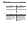
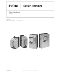
Cover Photo: The Cutler-Hammer® Intelligent Technology Soft Starter 65 mm, N-Frame
MN03902002E
For more information visit: www.EatonElectrical.com
i
IT. S811 Soft Starter User Manual
November 2004
Table of Contents
ii
LIST OF FIGURES . . . . . . . . . . . . . . . . . . . . . . . . . . . . . . . . . . . . . . . . . . . . . . . . . . . . . . . . .
LIST OF TABLES . . . . . . . . . . . . . . . . . . . . . . . . . . . . . . . . . . . . . . . . . . . . . . . . . . . . . . . . . .
CHAPTER 0 — SAFETY . . . . . . . . . . . . . . . . . . . . . . . . . . . . . . . . . . . . . . . . . . . . . . . . . . . .
The Meaning of Safety Statements . . . . . . . . . . . . . . . . . . . . . . . . . . . . . . . . . . . . . .
IT. Soft Starter Safety Statements . . . . . . . . . . . . . . . . . . . . . . . . . . . . . . . . . . . . . . .
Dangers, Warnings, Cautions and Notes . . . . . . . . . . . . . . . . . . . . . . . . . . . . . . . . . .
iv
v
vii
vii
viii
ix
CHAPTER 1 — OVERVIEW . . . . . . . . . . . . . . . . . . . . . . . . . . . . . . . . . . . . . . . . . . . . . . . . .
General Introduction . . . . . . . . . . . . . . . . . . . . . . . . . . . . . . . . . . . . . . . . . . . . . . . . . .
General Appearance Notes . . . . . . . . . . . . . . . . . . . . . . . . . . . . . . . . . . . . . . . . . . . . .
1-1
1-1
1-2
CHAPTER 2 — RECEIPT/UNPACKING . . . . . . . . . . . . . . . . . . . . . . . . . . . . . . . . . . . . . . . .
General . . . . . . . . . . . . . . . . . . . . . . . . . . . . . . . . . . . . . . . . . . . . . . . . . . . . . . . . . . . . .
Unpacking . . . . . . . . . . . . . . . . . . . . . . . . . . . . . . . . . . . . . . . . . . . . . . . . . . . . . . . . . . .
Storage . . . . . . . . . . . . . . . . . . . . . . . . . . . . . . . . . . . . . . . . . . . . . . . . . . . . . . . . . . . . .
2-1
2-1
2-1
2-1
CHAPTER 3 — INSTALLATION . . . . . . . . . . . . . . . . . . . . . . . . . . . . . . . . . . . . . . . . . . . . . .
Mounting. . . . . . . . . . . . . . . . . . . . . . . . . . . . . . . . . . . . . . . . . . . . . . . . . . . . . . . . . . . .
Power Wiring . . . . . . . . . . . . . . . . . . . . . . . . . . . . . . . . . . . . . . . . . . . . . . . . . . . . . . . .
Control Wiring Inputs. . . . . . . . . . . . . . . . . . . . . . . . . . . . . . . . . . . . . . . . . . . . . . . . . .
3-1
3-1
3-8
3-11
CHAPTER 4 — SPECIFICATIONS . . . . . . . . . . . . . . . . . . . . . . . . . . . . . . . . . . . . . . . . . . . .
Environmental . . . . . . . . . . . . . . . . . . . . . . . . . . . . . . . . . . . . . . . . . . . . . . . . . . . . . . .
Physical . . . . . . . . . . . . . . . . . . . . . . . . . . . . . . . . . . . . . . . . . . . . . . . . . . . . . . . . . . . . .
CE Conformance. . . . . . . . . . . . . . . . . . . . . . . . . . . . . . . . . . . . . . . . . . . . . . . . . . . . . .
Short Circuit Ratings . . . . . . . . . . . . . . . . . . . . . . . . . . . . . . . . . . . . . . . . . . . . . . . . . .
4-1
4-1
4-1
4-2
4-3
CHAPTER 5 — FUNCTIONAL DESCRIPTION . . . . . . . . . . . . . . . . . . . . . . . . . . . . . . . . . . .
Power . . . . . . . . . . . . . . . . . . . . . . . . . . . . . . . . . . . . . . . . . . . . . . . . . . . . . . . . . . . . . .
Control. . . . . . . . . . . . . . . . . . . . . . . . . . . . . . . . . . . . . . . . . . . . . . . . . . . . . . . . . . . . . .
Protection . . . . . . . . . . . . . . . . . . . . . . . . . . . . . . . . . . . . . . . . . . . . . . . . . . . . . . . . . . .
QCPort Network Control . . . . . . . . . . . . . . . . . . . . . . . . . . . . . . . . . . . . . . . . . . . . . . .
5-1
5-1
5-1
5-4
5-4
CHAPTER 6 — CONFIGURATION . . . . . . . . . . . . . . . . . . . . . . . . . . . . . . . . . . . . . . . . . . . .
Programming the S811 . . . . . . . . . . . . . . . . . . . . . . . . . . . . . . . . . . . . . . . . . . . . . . . .
S801 to S811 Comparison . . . . . . . . . . . . . . . . . . . . . . . . . . . . . . . . . . . . . . . . . . . . . .
6-1
6-1
6-2
CHAPTER 7 — SETUP AND STARTING . . . . . . . . . . . . . . . . . . . . . . . . . . . . . . . . . . . . . . .
Before You Begin . . . . . . . . . . . . . . . . . . . . . . . . . . . . . . . . . . . . . . . . . . . . . . . . . . . . .
Setup . . . . . . . . . . . . . . . . . . . . . . . . . . . . . . . . . . . . . . . . . . . . . . . . . . . . . . . . . . . . . . .
7-1
7-1
7-1
CHAPTER 8 — TROUBLESHOOTING . . . . . . . . . . . . . . . . . . . . . . . . . . . . . . . . . . . . . . . . .
General . . . . . . . . . . . . . . . . . . . . . . . . . . . . . . . . . . . . . . . . . . . . . . . . . . . . . . . . . . . . .
Before You Begin to Troubleshoot . . . . . . . . . . . . . . . . . . . . . . . . . . . . . . . . . . . . . . .
Define the Problem . . . . . . . . . . . . . . . . . . . . . . . . . . . . . . . . . . . . . . . . . . . . . . . . . . .
Fault Codes . . . . . . . . . . . . . . . . . . . . . . . . . . . . . . . . . . . . . . . . . . . . . . . . . . . . . . . . . .
8-1
8-1
8-1
8-2
8-6
CHAPTER 9 — PARTS AND SERVICE . . . . . . . . . . . . . . . . . . . . . . . . . . . . . . . . . . . . . . . . .
Renewal Parts . . . . . . . . . . . . . . . . . . . . . . . . . . . . . . . . . . . . . . . . . . . . . . . . . . . . . . . .
Service. . . . . . . . . . . . . . . . . . . . . . . . . . . . . . . . . . . . . . . . . . . . . . . . . . . . . . . . . . . . . .
9-1
9-1
9-1
For more information visit: www.EatonElectrical.com
MN03902002E
IT. S811 Soft Starter User Manual
November 2004
Table of Contents, Continued
MN03902002E
APPENDIX A — PARAMETERS . . . . . . . . . . . . . . . . . . . . . . . . . . . . . . . . . . . . . . . . . . . . . .
Parameter List . . . . . . . . . . . . . . . . . . . . . . . . . . . . . . . . . . . . . . . . . . . . . . . . . . . . . . . .
A-1
A-1
APPENDIX B — PROTECTION . . . . . . . . . . . . . . . . . . . . . . . . . . . . . . . . . . . . . . . . . . . . . . .
Thermal Overload . . . . . . . . . . . . . . . . . . . . . . . . . . . . . . . . . . . . . . . . . . . . . . . . . . . . .
Overload Trip Curves . . . . . . . . . . . . . . . . . . . . . . . . . . . . . . . . . . . . . . . . . . . . . . . . . .
S811 and Motor Protection Features . . . . . . . . . . . . . . . . . . . . . . . . . . . . . . . . . . . . . .
B-1
B-1
B-3
B-4
APPENDIX C— FAULTS . . . . . . . . . . . . . . . . . . . . . . . . . . . . . . . . . . . . . . . . . . . . . . . . . . . .
Fault Codes . . . . . . . . . . . . . . . . . . . . . . . . . . . . . . . . . . . . . . . . . . . . . . . . . . . . . . . . . .
C-1
C-1
APPENDIX D — RATINGS, COOLING AND POWER LOSSES . . . . . . . . . . . . . . . . . . . . . .
Horsepower and kW Ratings . . . . . . . . . . . . . . . . . . . . . . . . . . . . . . . . . . . . . . . . . . . .
Cooling . . . . . . . . . . . . . . . . . . . . . . . . . . . . . . . . . . . . . . . . . . . . . . . . . . . . . . . . . . . . . .
Power Losses . . . . . . . . . . . . . . . . . . . . . . . . . . . . . . . . . . . . . . . . . . . . . . . . . . . . . . . . .
D-1
D-1
D-8
D-8
APPENDIX E — MOTOR/APPLICATION CONSIDERATIONS . . . . . . . . . . . . . . . . . . . . . . .
Using MOVs . . . . . . . . . . . . . . . . . . . . . . . . . . . . . . . . . . . . . . . . . . . . . . . . . . . . . . . . . .
Squirrel Cage Motor . . . . . . . . . . . . . . . . . . . . . . . . . . . . . . . . . . . . . . . . . . . . . . . . . . .
Wye-Delta Motor . . . . . . . . . . . . . . . . . . . . . . . . . . . . . . . . . . . . . . . . . . . . . . . . . . . . . .
Part Winding Motor. . . . . . . . . . . . . . . . . . . . . . . . . . . . . . . . . . . . . . . . . . . . . . . . . . . .
Dual Voltage Motor . . . . . . . . . . . . . . . . . . . . . . . . . . . . . . . . . . . . . . . . . . . . . . . . . . . .
Multi-Speed Motor . . . . . . . . . . . . . . . . . . . . . . . . . . . . . . . . . . . . . . . . . . . . . . . . . . . .
Other Winding Configurations . . . . . . . . . . . . . . . . . . . . . . . . . . . . . . . . . . . . . . . . . . .
Power Factor Correction Capacitors . . . . . . . . . . . . . . . . . . . . . . . . . . . . . . . . . . . . . .
E-1
E-1
E-1
E-2
E-2
E-2
E-2
E-3
E-3
APPENDIX F — SPECIAL FUNCTION OPTIONS . . . . . . . . . . . . . . . . . . . . . . . . . . . . . . . . .
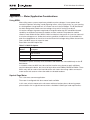
Pump Control Option . . . . . . . . . . . . . . . . . . . . . . . . . . . . . . . . . . . . . . . . . . . . . . . . . .
Extended Ramp Option. . . . . . . . . . . . . . . . . . . . . . . . . . . . . . . . . . . . . . . . . . . . . . . . .
F-1
F-1
F-2
APPENDIX G — USER INTERFACE — DIM . . . . . . . . . . . . . . . . . . . . . . . . . . . . . . . . . . . . .
Modes of Operation . . . . . . . . . . . . . . . . . . . . . . . . . . . . . . . . . . . . . . . . . . . . . . . . . . .
Button Operation . . . . . . . . . . . . . . . . . . . . . . . . . . . . . . . . . . . . . . . . . . . . . . . . . . . . . .
Areas of the Screen . . . . . . . . . . . . . . . . . . . . . . . . . . . . . . . . . . . . . . . . . . . . . . . . . . . .
Parameter Navigation/Editing . . . . . . . . . . . . . . . . . . . . . . . . . . . . . . . . . . . . . . . . . . .
Access Level (Password) Operation. . . . . . . . . . . . . . . . . . . . . . . . . . . . . . . . . . . . . . .
Fault Display . . . . . . . . . . . . . . . . . . . . . . . . . . . . . . . . . . . . . . . . . . . . . . . . . . . . . . . . .
DIM System Configuration . . . . . . . . . . . . . . . . . . . . . . . . . . . . . . . . . . . . . . . . . . . . . .
DIM Setup Parameter Description . . . . . . . . . . . . . . . . . . . . . . . . . . . . . . . . . . . . . . . .
G-1
G-2
G-3
G-5
G-8
G-11
G-12
G-13
G-14
APPENDIX H — QCPORT NETWORK . . . . . . . . . . . . . . . . . . . . . . . . . . . . . . . . . . . . . . . . .
QCPort Communication Wiring . . . . . . . . . . . . . . . . . . . . . . . . . . . . . . . . . . . . . . . . . .
Networks . . . . . . . . . . . . . . . . . . . . . . . . . . . . . . . . . . . . . . . . . . . . . . . . . . . . . . . . . . . .
Auto and Hand/Local Modes . . . . . . . . . . . . . . . . . . . . . . . . . . . . . . . . . . . . . . . . . . . .
H-1
H-1
H-3
H-5
APPENDIX I — QCPORT PARAMETER DESCRIPTIONS . . . . . . . . . . . . . . . . . . . . . . . . . . .
Data Parameters . . . . . . . . . . . . . . . . . . . . . . . . . . . . . . . . . . . . . . . . . . . . . . . . . . . . . .
Configuration Parameters. . . . . . . . . . . . . . . . . . . . . . . . . . . . . . . . . . . . . . . . . . . . . . .
I-1
I-1
I-6
For more information visit: www.EatonElectrical.com
iii
IT. S811 Soft Starter User Manual
November 2004
List of Figures
Figure 1-1: The Cutler-Hammer Intelligent Technologies (IT.) S811 Soft Starter . . . . . .
Figure 3-1: Warning Tag . . . . . . . . . . . . . . . . . . . . . . . . . . . . . . . . . . . . . . . . . . . . . . . . . . .
Figure 3-2: Power Wiring Alternatives . . . . . . . . . . . . . . . . . . . . . . . . . . . . . . . . . . . . . . . .
Figure 3-3: N Frame (65 mm) . . . . . . . . . . . . . . . . . . . . . . . . . . . . . . . . . . . . . . . . . . . . . . .
Figure 3-4: R Frame (110 mm) . . . . . . . . . . . . . . . . . . . . . . . . . . . . . . . . . . . . . . . . . . . . . .
Figure 3-5: T Frame (200 mm) . . . . . . . . . . . . . . . . . . . . . . . . . . . . . . . . . . . . . . . . . . . . . . .
Figure 3-6: V Frame (290 mm) . . . . . . . . . . . . . . . . . . . . . . . . . . . . . . . . . . . . . . . . . . . . . .
Figure 3-7: EMA91 Digital Interface Module . . . . . . . . . . . . . . . . . . . . . . . . . . . . . . . . . . .
Figure 3-8: V Frame Shown with Terminal Cover Removed
and EML30 Lug Kit Installed on Load Side . . . . . . . . . . . . . . . . . . . . . . . . . . . . . . . . .
Figure 3-9: Terminal Block . . . . . . . . . . . . . . . . . . . . . . . . . . . . . . . . . . . . . . . . . . . . . . . . . .
Figure 3-10: Basic Connection Diagram for 24V DC 3-Wire Pushbutton
STOP/START/JOG/RESET and 24V DC Fault/Ready and Bypass Indication . . . . . . .
Figure 3-11: Basic Connection Diagram for 24V DC 2-Wire Switch
HAND/OFF/AUTO/RESET and 24V DC Fault/Ready and Bypass Indication . . . . . . .
Figure 3-12: Basic Connection Diagram for Use of DIM Control Only . . . . . . . . . . . . . .
Figure 3-13: 24V DC Control . . . . . . . . . . . . . . . . . . . . . . . . . . . . . . . . . . . . . . . . . . . . . . . .
Figure 3-14: 120V AC Control . . . . . . . . . . . . . . . . . . . . . . . . . . . . . . . . . . . . . . . . . . . . . . .
Figure 3-15: 24V DC Control with Edge Sensing . . . . . . . . . . . . . . . . . . . . . . . . . . . . . . . .
Figure 5-1: Soft Starter SCRs . . . . . . . . . . . . . . . . . . . . . . . . . . . . . . . . . . . . . . . . . . . . . . .
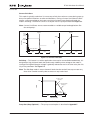
Figure 5-2: Ramp Start . . . . . . . . . . . . . . . . . . . . . . . . . . . . . . . . . . . . . . . . . . . . . . . . . . . . .
Figure 5-3: Current Limit Start . . . . . . . . . . . . . . . . . . . . . . . . . . . . . . . . . . . . . . . . . . . . . .
Figure 5-4: Soft Stop . . . . . . . . . . . . . . . . . . . . . . . . . . . . . . . . . . . . . . . . . . . . . . . . . . . . . .
Figure 6-1: Digital Interface Module (DIM) — Display Mode . . . . . . . . . . . . . . . . . . . . . .
Figure 6-2: Digital Interface Module (DIM) — Parameter Edit Mode . . . . . . . . . . . . . . . .
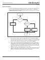
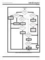
Figure 8-1: Start Command Troubleshooting Flowchart . . . . . . . . . . . . . . . . . . . . . . . . .
Figure 8-2: Main Troubleshooting Flowchart #1 . . . . . . . . . . . . . . . . . . . . . . . . . . . . . . . .
Figure A-1: Navigation Overview . . . . . . . . . . . . . . . . . . . . . . . . . . . . . . . . . . . . . . . . . . . .
Figure B-1: Overload Trip Curves . . . . . . . . . . . . . . . . . . . . . . . . . . . . . . . . . . . . . . . . . . . .
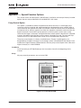
Figure F-1: IT. Soft Starter DIM . . . . . . . . . . . . . . . . . . . . . . . . . . . . . . . . . . . . . . . . . . . . . .
Figure F-2: Pump Start Ramp and Soft Pump Stop . . . . . . . . . . . . . . . . . . . . . . . . . . . . .
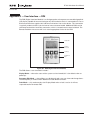
Figure G-1: DIM (Digital Interface Module) . . . . . . . . . . . . . . . . . . . . . . . . . . . . . . . . . . . .
Figure G-2: Display Mode LCD . . . . . . . . . . . . . . . . . . . . . . . . . . . . . . . . . . . . . . . . . . . . . .
Figure G-3: Parameter Edit Mode LCD . . . . . . . . . . . . . . . . . . . . . . . . . . . . . . . . . . . . . . . .
Figure G-4: Fault Mode LCD . . . . . . . . . . . . . . . . . . . . . . . . . . . . . . . . . . . . . . . . . . . . . . . .
Figure G-5: Soft Key Functions
Above Soft Keys . . . . . . . . . . . . . . . . . . . . . . . . . . . . . . . . . . . . . . . . . . . . . . . . . . . . . .
Figure G-6: Predefined Keys . . . . . . . . . . . . . . . . . . . . . . . . . . . . . . . . . . . . . . . . . . . . . . . .
Figure G-7: Status Bar on LCD . . . . . . . . . . . . . . . . . . . . . . . . . . . . . . . . . . . . . . . . . . . . . .
Figure G-8: Device Connection
(User Display Only) . . . . . . . . . . . . . . . . . . . . . . . . . . . . . . . . . . . . . . . . . . . . . . . . . . . .
Figure G-9: Connection Status . . . . . . . . . . . . . . . . . . . . . . . . . . . . . . . . . . . . . . . . . . . . . .
Figure G-10: Mode of Operation . . . . . . . . . . . . . . . . . . . . . . . . . . . . . . . . . . . . . . . . . . . . .
Figure G-11: Connection Destination . . . . . . . . . . . . . . . . . . . . . . . . . . . . . . . . . . . . . . . . .
Figure G-12: HAND/AUTO Status . . . . . . . . . . . . . . . . . . . . . . . . . . . . . . . . . . . . . . . . . . . .
Figure G-13: Motor Control Status . . . . . . . . . . . . . . . . . . . . . . . . . . . . . . . . . . . . . . . . . . .
Figure G-14: Bar Indicates Menu Position . . . . . . . . . . . . . . . . . . . . . . . . . . . . . . . . . . . . .
Figure G-15: Bar Indicates Item Position . . . . . . . . . . . . . . . . . . . . . . . . . . . . . . . . . . . . . .
Figure G-16: Bar Indicates Edited Value . . . . . . . . . . . . . . . . . . . . . . . . . . . . . . . . . . . . . . .
Figure G-17: Use MORE to Highlight Element . . . . . . . . . . . . . . . . . . . . . . . . . . . . . . . . . .
Figure G-18: Setting Access Level . . . . . . . . . . . . . . . . . . . . . . . . . . . . . . . . . . . . . . . . . . .
iv
For more information visit: www.EatonElectrical.com
1-2
3-2
3-3
3-4
3-4
3-5
3-5
3-6
3-10
3-11
3-13
3-14
3-14
3-19
3-19
3-20
5-1
5-2
5-3
5-3
6-1
6-2
8-2
8-4
A-1
B-3
F-1
F-2
G-1
G-2
G-2
G-2
G-3
G-4
G-5
G-5
G-5
G-6
G-7
G-7
G-7
G-8
G-8
G-9
G-10
G-11
MN03902002E
IT. S811 Soft Starter User Manual
November 2004
List of Figures, Continued
Figure G-19: Changing Passwords . . . . . . . . . . . . . . . . . . . . . . . . . . . . . . . . . . . . . . . . . . .
Figure G-20: Fault Display . . . . . . . . . . . . . . . . . . . . . . . . . . . . . . . . . . . . . . . . . . . . . . . . . .
Figure H-1: QCP Network Wiring . . . . . . . . . . . . . . . . . . . . . . . . . . . . . . . . . . . . . . . . . . . . .
Figure H-2: Two-Wire QCPort System . . . . . . . . . . . . . . . . . . . . . . . . . . . . . . . . . . . . . . . . .
Figure H-3: Three-Wire QCPort System . . . . . . . . . . . . . . . . . . . . . . . . . . . . . . . . . . . . . . .
Figure H-4: S811 Motor Control Byte . . . . . . . . . . . . . . . . . . . . . . . . . . . . . . . . . . . . . . . . .
G-12
G-12
H-2
H-3
H-4
H-6
List of Tables
Table 3-1: Required Mounting Hardware . . . . . . . . . . . . . . . . . . . . . . . . . . . . . . . . . . . . . . .
Table 3-2: Weight Support Requirements . . . . . . . . . . . . . . . . . . . . . . . . . . . . . . . . . . . . . .
Table 3-3: Line and Load Power Wiring . . . . . . . . . . . . . . . . . . . . . . . . . . . . . . . . . . . . . . . .
Table 3-4: 12-Pin Terminal Block Wiring Capacity . . . . . . . . . . . . . . . . . . . . . . . . . . . . . . . .
Table 3-5: S811 Terminal Block Control Wiring . . . . . . . . . . . . . . . . . . . . . . . . . . . . . . . . . .
Table 3-6: 24V DC Power Supply Requirements . . . . . . . . . . . . . . . . . . . . . . . . . . . . . . . . .
Table 3-7: 24V DC Power Supplies . . . . . . . . . . . . . . . . . . . . . . . . . . . . . . . . . . . . . . . . . . . .
Table 4-1: Environmental Specifications . . . . . . . . . . . . . . . . . . . . . . . . . . . . . . . . . . . . . . .
Table 4-2: Weight . . . . . . . . . . . . . . . . . . . . . . . . . . . . . . . . . . . . . . . . . . . . . . . . . . . . . . . . . .
Table 4-3: Agency Standards and Certifications . . . . . . . . . . . . . . . . . . . . . . . . . . . . . . . . .
Table 4-4: EMC Immunity . . . . . . . . . . . . . . . . . . . . . . . . . . . . . . . . . . . . . . . . . . . . . . . . . . .
Table 4-5: Short Circuit Ratings. . . . . . . . . . . . . . . . . . . . . . . . . . . . . . . . . . . . . . . . . . . . . . .
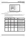
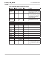
Table 6-1: S801 to S811 Setup Cross-Reference . . . . . . . . . . . . . . . . . . . . . . . . . . . . . . . . .
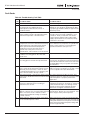
Table 8-1: Start Command Troubleshooting . . . . . . . . . . . . . . . . . . . . . . . . . . . . . . . . . . . .
Table 8-2: Troubleshooting – Status LED OFF . . . . . . . . . . . . . . . . . . . . . . . . . . . . . . . . . . .
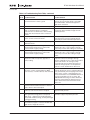
Table 8-3: Troubleshooting – Status LED GREEN . . . . . . . . . . . . . . . . . . . . . . . . . . . . . . . .
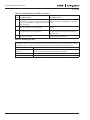
Table 8-4: Troubleshooting Fault Table . . . . . . . . . . . . . . . . . . . . . . . . . . . . . . . . . . . . . . . .
Table 8-5: Resetting the S811 . . . . . . . . . . . . . . . . . . . . . . . . . . . . . . . . . . . . . . . . . . . . . . . .
Table 9-1: DIM – Digital Interface Module Renewal Parts . . . . . . . . . . . . . . . . . . . . . . . . . .
Table A-1: Monitoring — Menu 1 . . . . . . . . . . . . . . . . . . . . . . . . . . . . . . . . . . . . . . . . . . . . .
Table A-2: Motor Control — Menu 2. . . . . . . . . . . . . . . . . . . . . . . . . . . . . . . . . . . . . . . . . . .
Table A-3: Configuration — Menu 3 . . . . . . . . . . . . . . . . . . . . . . . . . . . . . . . . . . . . . . . . . . .
Table A-4: Protections — Menu 4 . . . . . . . . . . . . . . . . . . . . . . . . . . . . . . . . . . . . . . . . . . . . .
Table A-5: Network Setup — Menu 5 . . . . . . . . . . . . . . . . . . . . . . . . . . . . . . . . . . . . . . . . . .
Table A-6: Network Status — Menu 6. . . . . . . . . . . . . . . . . . . . . . . . . . . . . . . . . . . . . . . . . .
Table A-7: LCD DIM Setup Menu . . . . . . . . . . . . . . . . . . . . . . . . . . . . . . . . . . . . . . . . . . . . .
Table B-1: Overload — Adjustment Settings . . . . . . . . . . . . . . . . . . . . . . . . . . . . . . . . . . . .
Table B-2: Thermal Motor Overload Times . . . . . . . . . . . . . . . . . . . . . . . . . . . . . . . . . . . . .
Table B-3: Motor Parameters Required for Protection . . . . . . . . . . . . . . . . . . . . . . . . . . . .
Table B-4: Instantaneous Over Current Settings . . . . . . . . . . . . . . . . . . . . . . . . . . . . . . . . .
Table B-5: Motor Stall Settings . . . . . . . . . . . . . . . . . . . . . . . . . . . . . . . . . . . . . . . . . . . . . . .
Table B-6: SCR Over Current Settings . . . . . . . . . . . . . . . . . . . . . . . . . . . . . . . . . . . . . . . . .
Table B-7: Motor Jam Settings . . . . . . . . . . . . . . . . . . . . . . . . . . . . . . . . . . . . . . . . . . . . . . .
Table B-8: Motor Over Current Settings . . . . . . . . . . . . . . . . . . . . . . . . . . . . . . . . . . . . . . . .
Table B-9: Motor Under Load Settings . . . . . . . . . . . . . . . . . . . . . . . . . . . . . . . . . . . . . . . . .
Table B-10: Current Imbalance Settings . . . . . . . . . . . . . . . . . . . . . . . . . . . . . . . . . . . . . . . .
Table B-11: Phase Loss Settings . . . . . . . . . . . . . . . . . . . . . . . . . . . . . . . . . . . . . . . . . . . . . .
Table B-12: Motor Voltage Phase Reversal Settings . . . . . . . . . . . . . . . . . . . . . . . . . . . . . .
Table B-13: Voltage Imbalance Settings . . . . . . . . . . . . . . . . . . . . . . . . . . . . . . . . . . . . . . . .
Table B-14: Under Voltage Settings . . . . . . . . . . . . . . . . . . . . . . . . . . . . . . . . . . . . . . . . . . .
Table B-15: Over Voltage Settings . . . . . . . . . . . . . . . . . . . . . . . . . . . . . . . . . . . . . . . . . . . .
Table B-16: Fault Generation . . . . . . . . . . . . . . . . . . . . . . . . . . . . . . . . . . . . . . . . . . . . . . . . .
Table B-17: S811 Protection Faults . . . . . . . . . . . . . . . . . . . . . . . . . . . . . . . . . . . . . . . . . . . .
Table C-1: Troubleshooting Fault Table . . . . . . . . . . . . . . . . . . . . . . . . . . . . . . . . . . . . . . . .
MN03902002E
For more information visit: www.EatonElectrical.com
3-7
3-7
3-9
3-11
3-12
3-15
3-16
4-1
4-1
4-1
4-2
4-3
6-2
8-3
8-5
8-5
8-6
8-8
9-1
A-2
A-3
A-4
A-5
A-6
A-7
A-8
B-1
B-2
B-4
B-4
B-4
B-4
B-5
B-5
B-5
B-5
B-6
B-6
B-6
B-7
B-7
B-7
B-8
C-1
v
IT. S811 Soft Starter User Manual
November 2004
List of Tables, Continued
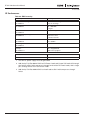
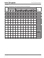
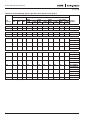
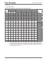
Table D-1: 15 Second Ramp, 4 Starts per Hour, 300% Current Limit @ 40°C . . . . . . . . .
Table D-2: 25 Second Ramp, 4 Starts per Hour, 300% Current Limit @ 40°C . . . . . . . . .
Table D-3: 15 Second Ramp, 4 Starts per Hour, 300% Current Limit @ 50°C . . . . . . . . .
Table D-4: 50 Second Ramp, 2 Starts per Hour, 300% Current Limit @ 50°C . . . . . . . . .
Table D-5: 15 Second Ramp, 4 Starts per Hour, 450% Current Limit @ 40°C . . . . . . . . .
Table D-6: 30 Second Ramp, 4 Starts per Hour, 450% Current Limit @ 40°C . . . . . . . . .
Table D-7: > 30 Second Ramp, > 4 Starts per Hour or >300% Current Limit . . . . . . . . . .
Table D-8: Maximum Power Loss . . . . . . . . . . . . . . . . . . . . . . . . . . . . . . . . . . . . . . . . . . . .
Table E-1: MOV Kit Options . . . . . . . . . . . . . . . . . . . . . . . . . . . . . . . . . . . . . . . . . . . . . . . . .
Table G-1: Access Levels . . . . . . . . . . . . . . . . . . . . . . . . . . . . . . . . . . . . . . . . . . . . . . . . . . .
Table G-2: Reconfiguring All Devices . . . . . . . . . . . . . . . . . . . . . . . . . . . . . . . . . . . . . . . . .
Table G-3: LCD DIM Setup Menu Access . . . . . . . . . . . . . . . . . . . . . . . . . . . . . . . . . . . . . .
vi
For more information visit: www.EatonElectrical.com
D-1
D-2
D-3
D-4
D-5
D-6
D-7
D-8
E-1
G-11
G-13
G-14
MN03902002E
IT. S811 Soft Starter User Manual
November 2004
Safety
Eaton’s electrical business has made every effort to provide you with the safest motor
starters on the market. However, we wish to point out how to safely operate and troubleshoot
your starter.
The Meaning of Safety Statements
You will find various types of safety information on the following pages and on the labels
attached to the equipment. This section explains their meaning.
!
!
The Safety Alert Symbol means ATTENTION! BECOME ALERT!
YOUR SAFETY IS INVOLVED!
Le symbole d’alerte signifie ATTENTION! SOYEZ VIGILANT!
VOTRE SECURITE EST EN JEU!
Danger
Danger means that failure to follow the safety
statement will result in serious personal injury,
death, or substantial property damage.
Danger
Danger signifie que l’inobservation de l’énoncé de
sécurité entraînera des blessures corporelles
graves, la mort ou des dégâts matériels
substantiels.
Warning
Warning means that failure to follow the safety
statement could result in serious personal injury,
death, or substantial property damage.
!
Avertissement
Avertissement signifie que l’inobservation de
l’énoncé de sécurité pourrait entraîner des
blessures corporelles graves, la mort ou des
dégâts matériels substantiels.
Caution
Caution means that failure to follow the safety
statement may result in minor or moderate
personal injury or property damage.
!
Attention
Attention signifie que l’inobservation de l’énoncé
de sécurité peut entraîner des blessures
corporelles mineures ou modérés ou des dégâts
matériels.
Notice
Avis
Avis signifie que l’inobservation de ses
Notice means that failure to follow these
instructions could cause damage to the equipment instructions pourrait entraîner des dégâts à ou le
mauvais fonctionnement de l’équipement.
or cause it to operate improperly.
MN03902002E
For more information visit: www.EatonElectrical.com
vii
IT. S811 Soft Starter User Manual
November 2004
IT. Soft Starter Safety Statements
The following safety statements relate to the installation, operation, and troubleshooting of
Cutler-Hammer® Motor Starters.
Notice
Avis
Make sure you read and understand the
Bien lire et comprendre les procédures
installation procedures in this manual before you d’installation contenues dans ce manuel avant de
attempt to operate or troubleshoot the equipment. tenter l’opération ou la régulation des problèmes
de cet équipement.
Warning
The instruction manual should be used for proper
installation, operation, and maintenance of the
equipment. Improperly installing and maintaining
these products can result in serious personal
injury or property damage. Before attempting
installation or maintenance, read and understand
this entire manual.
Avertissement
Consulter le manuel pour des instructions relatives
à l’installation, opération, et entretien réglés de
l’équipement. La mauvaise installation et entretien
de ses produits pourraient entraîner des blessures
corporelles graves ou des dégâts matériels. Avant
de tenter l’installation ou l’entretien, bien lire et
comprendre ce manuel en entier.
Danger Haute Tension
Danger High Voltage
viii
There can be line voltage potential at the motor
load terminals even with the starter in the off state.
This is due to the possible leakage across SCRs.
Always disconnect input power before servicing
starter or motor.
Il peut exister une tension de ligne potentielle aux
bornes de charge du moteur bien que le
démarreur soit dans en état d’arrêt. Cela
s’explique du fait de fuites possibles à travers les
redresseurs au silicium. Toujours débrancher
l’alimentation avant de travailler sur le démarreur
ou le moteur.
Notice
Avis
Power factor capacitors: Do not connect power
factor correcting capacitors to the load side of the
starter. They will cause the starter to fail. If
capacitors are used, they must be connected to the
line side of the starter, as far upstream as possible.
Condensateurs de compensation : Ne pas
raccorder ces appareils au côté charge du
démarreur. Cela entraînera la défaillance du
démarreur. Si des condensateurs sont utilisés, ils
doivent être raccorder au côté ligne du démarreur,
aussi loin amont que possible.
For more information visit: www.EatonElectrical.com
MN03902002E
IT. S811 Soft Starter User Manual
November 2004
Dangers, Warnings, Cautions and Notes
Dangers
Danger High Voltage
Danger Haute Tension
Hazard of Burn or Electrical Shock
Risque de Brûlure ou de Choc Electrique
To avoid shock hazard, disconnect all power to the
controller, motor or other control devices before
any work is performed on this equipment. Failure
to do so will result in personal injury, death or
substantial property damage.
Pour éviter des chocs électriques, débrancher
l’alimentation du contrôleur, du moteur ou des
autres appareils de contrôle avant d’y effectuer du
travail. L’inobservation de ces instructions
entraînera des blessures corporelles graves, la
mort ou des dégâts matériels substantiels.
Do not apply a disconnect device on the output of
the IT. Soft Starter unless a means to turn off the
soft starter when disconnect switch is open is
utilized. Opening disconnect while the IT. Soft
Starter is operating may cause a malfunction.
Closing disconnect switch while the IT. Soft Starter
is operating will result in a soft starter failure and
potential equipment damage and personnel
hazard.
Ne pas appliquer un appareil de sectionnement
sur la sortie du démarreur progressif IT. à moins
qu’un moyen d’éteindre le démarreur progressif
quand l’interrupteur de sectionnement est ouvert
soit utilisé. Le fait d’ouvrir l’interrupteur de
sectionnement pendant le fonctionnement du
démarreur progressif IT. peut entraîner une
défaillance. Le fait d’éteindre l’interrupteur de
sectionnement pendant le fonctionnement du
démarreur progressif IT. entraînera la défaillance
du démarreur progressif et des dégâts à
l’équipement ou risque au personnel.
Danger High Voltage
Hazard of Burn or Electrical Shock
Make sure all power is off before wiring.
Danger Haute Tension
Risque de Brûlure ou de Choc Electrique
Vérifier que toute alimentation est débrancher
avant de câbler.
Danger High Voltage
The S811 has the ability to respond to commands
from an automated network controller.
Consequently the soft starter may start
unexpectedly in response to these commands. To
insure the safety of personnel and equipment,
always remove power before accessing the
electrical and/or mechanical equipment.
Danger Haute Tension
Le S811 à la capacité de répondre aux commandes
d’un contrôleur de réseau automatisé. Donc le
démarreur progressif peut démarrer
soudainement en réponse à ces commandes. Pour
s’assurer la sécurité du personnel et de
l’équipement, toujours débrancher l’alimentation
avant d’accéder à l’équipement électrique et/ou
mécanique.
Danger High Voltage
Do not work on energized equipment unless
absolutely required. If troubleshooting procedure
requires equipment to be energized, all work must
be performed by properly qualified personnel,
following appropriate safety practices and
precautionary measures.
MN03902002E
Danger Haute Tension
Ne pas travailler sur d’équipement sous tension
sauf si c’est absolument nécessaire. Si des
méthodes de dépannage exigent que
l’équipement soit sous tension, tout travail doit
être faire par du personnel qualifié, suivant des
pratiques de sécurité et des mesures de précaution
appropriées.
For more information visit: www.EatonElectrical.com
ix
IT. S811 Soft Starter User Manual
November 2004
Warnings
Warning
After mounting the unit, remove and discard the
lifting eye and packaging bolts before continuing
with the installation process.
Avertissement
Après que l’appareil sera supporté, enlever et jeter
les œillets de levage et les boulons de l’emballage
avant de poursuivre l’installation.
Warning
Make sure you read and understand all of the
safety statements in the safety section of this
manual before you begin troubleshooting.
Avertissement
S’assurer de bien lire et comprendre les énoncés
de sécurité dans le passage de sécurité de ce
manuel avant de commencer le dépannage.
Cautions
!
Caution
The S811V soft starter weighs approximately
100 Lbs. (45 kg). To prevent personal injury or
equipment damage, use proper lifting equipment
(such as a floor crane) to safely lift and install the
soft starter. A lifting eye is provided at the line end
of the soft starter.
!
Attention
Le démarreur progressif S811V pèse environ 45 kg
(100 livres). Pour éviter des blessures corporelles
ou des dégâts matériels, utiliser une machine de
levage appropriée (comme une grue d’atelier)
pour soulever et installer le démarreur progressif
sans encombre. Un œillet de levage est prévu au
côté ligne du démarreur progressif.
Caution
Only apply 24V DC to the terminal block unless
specified otherwise in this manual. All control
wiring is 22 – 12 AWG (0.33 – 2.5 mm2). Failure to
follow this caution could result in severe damage
to the controller.
!
!
!
Attention
Appliquer seulement 24V CC à la barrette à bornes
sauf ce manuel offre d’avis contraire. Tout le
câblage de commande est de calibre 0.33 –
2.5 mm2 (22 – 12 AWG). L’inobservation de cet
énoncé pourrait entraîner des dégâts matériels au
contrôleur.
Caution
!
Attention
Never megger a motor while it is connected to the Ne jamais régler un moteur alors qu’il est branché
IT. Soft Starter. Disconnect the leads at the IT. Soft au démarreur progressif IT. Débrancher les fils au
Starter before meggering the motor.
démarreur progressif IT. Avant de régler le moteur.
!
Caution
Soft Stop is not an emergency stop, and cannot
make the load stop faster than its normal coastto-stop time. If removal of control is desired,
additional control is required to open up the
24V DC to terminal +. Using terminal P to initiate
power removal is not recommended.
x
!
Attention
Le ralentissement progressif n’est pas une
commande d’arrêt d’urgence et ne peut pas servir
à accélérer l’arrêt de la charge par rapport au
temps de ralentissement programmé. Si le retrait
de la commande est souhaité, un contrôle
supplémentaire est requis pour ouvrir le 24V CC à
la borne +. Il n’est pas recommandé de
commencer à couper l’alimentation à partir de la
borne P.
For more information visit: www.EatonElectrical.com
MN03902002E
IT. S811 Soft Starter User Manual
November 2004
Cautions, continued
!
Caution
Soft Stop is not an emergency stop. If a quick stop
is desired, additional control is required to open
up the 24V DC to terminal +. Using terminal P for a
quick stop is not recommended.
!
!
Attention
Le ralentissement progressif n’est pas une
commande d’arrêt d’urgence. Si un arrêt rapide et
désiré, un contrôle supplémentaire est requis pour
ouvrir le 24V CC à la borne +. Il n’est pas
recommandé d’utiliser la borne P pour un arrêt
rapide.
Caution
!
Attention
Soft Stop does not provide any braking. It cannot
cause the motor and its load to stop faster than
their normal unpowered coast down time.
Le ralentissement progressif n’assure aucun
freinage. Il ne peut pas servir à accélérer l’arrêt du
moteur et sa charge par rapport au temps de
ralentissement programmé.
Notice
Avis
The S811V Soft Starter includes mounting
hardware (8 1/4-20 x 1.5 Allen hex head cap screws
and special washers). Do not substitute for this
hardware. See Figure 3-6 on Page 3-5 for panel
hole locations. Applicable codes or standards
must be considered before locating and mounting
the soft starter. The four special rectangular/
rounded washers must be used on the two
innermost mounting holes on both the line and
load side of the soft starter.
Le démarreur progressif S811V inclut des
matériels de support (vis à tête hexagonale
8-1/4-20 x 1,5 et des rondelles spéciales). Ne
substituer pas pour ces matériels. Consulter la
Figure 3-6 de la Page 3-5 pour les locations des
trous dans le panneau. Tenir compte des normes
et des codes existants avant de localiser et de
monter le démarreur progressif. Les quatre
rondelles rectangulaires/circulaires spéciales
doivent être utiliser aux deux trous de support les
plus intérieurs sur le côté ligne et le côté charge du
démarreur progressif.
Notes
MN03902002E
For more information visit: www.EatonElectrical.com
xi
IT. S811 Soft Starter User Manual
November 2004
xii
For more information visit: www.EatonElectrical.com
MN03902002E
IT. S811 Soft Starter User Manual
November 2004
Chapter 1 — Overview
General Introduction
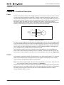
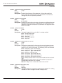
The Cutler-Hammer® Intelligent Technologies S811 IT. Soft Starter from Eaton’s electrical
business is an electronic, self-contained, panel- or enclosure-mounted motor soft-starting
device. It is intended to provide three-phase induction motors with a smooth start, both
mechanically and electrically. The S811 Soft Starters utilize six SCRs connected in a full wave
power bridge. Varying the SCR conduction period controls the voltage applied to the motor.
This in turn controls the torque developed by the motor. After the motor reaches speed,
contacts are closed to bypass the SCRs.
The S811 has built-in communications capabilities through Cutler-Hammer QC (Quick
Connect) Port. The S811 Soft Starter utilizes a DIM (Digital Interface Module) that allows the
user to configure the device and read system parameters. The DIM includes an easy-to-read
LCD display and keypad to scroll through the menus. The DIM allows the user to modify
control parameters, enable or disable protections, set communication variables, monitor
system parameters such as line voltages and currents and access the fault queue.
The S811 is designed to fulfill the industrial service requirements for applications such as
Chillers, Pumps and Machine Tools that require less than 85% of the motor’s rated starting
torque for worst case starting condition.
The S811 meets all relevant specifications set forth by NEMA ICS 1, ICS 2 and ICS 5, UL 508,
IEC 60947-4-2, CE and CSA.
This user manual covers everything you need to know in order to install, set up, operate,
troubleshoot and maintain the S811.
However, no publication can take into account every possible situation. If you require further
assistance with any aspect of this product, or a particular application, please contact us.
For contact information, please see Chapter 9.
MN03902002E
For more information visit: www.EatonElectrical.com
1-1
IT. S811 Soft Starter User Manual
November 2004
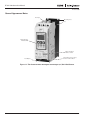
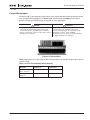
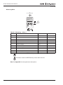
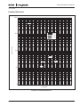
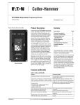
General Appearance Notes
Line Input
Mounting Slots
Base
Digital Interface
Module (DIM)
QC Port Network
Address Switch
Load Output
Detachable 12-Pin Locking
Control Terminal Block
Figure 1-1: The Cutler-Hammer Intelligent Technologies (IT.) S811 Soft Starter
1-2
For more information visit: www.EatonElectrical.com
MN03902002E
IT. S811 Soft Starter User Manual
November 2004
Chapter 2 — Receipt/Unpacking
General
Upon receipt of the unit, verify that the catalog number and unit options stated on the
shipping container match those stated on the order/purchase form.
Inspect the equipment upon delivery. Report any crate or carton damage to the carrier prior
to accepting the delivery. Have this information noted on the freight bill. Eaton is not
responsible for damage incurred in shipping.
Unpacking
Remove all packing material from the unit. Be sure to remove all packing material from lug
locations. Also, make sure no packing material blocks the airflow near the fans. For V frame
units, verify mounting hardware has been included with shipment.
Check the unit for any signs of shipping damage. If damage is found after unpacking, report it
to the freight company. Retain the packaging materials for carrier to review.
Verify that the unit’s catalog number and options match those stated on the order/purchase
form.
Storage
It is recommended that the unit be stored in its original shipping box/crate until it is to be
installed.
The unit should be stored in a location where:
MN03902002E
●
The ambient temperature is -58°F – 158°F (-50°C – 70°C)
●
The relative humidity is 0% – 95%, non-condensing
●
The environment is dry, clean and non-corrosive
●
The unit will not be subjected to high shock or vibration conditions
For more information visit: www.EatonElectrical.com
2-1
IT. S811 Soft Starter User Manual
November 2004
2-2
For more information visit: www.EatonElectrical.com
MN03902002E
IT. S811 Soft Starter User Manual
October 2004
Chapter 3 — Installation
Mounting
Models S811N, S811R and S811T
The S811 is easy to mount. It does not require any special tools.
To aid you with panel layout, refer to the dimension drawings in Figures 3-3 through 3-6 of
this manual. Drill and tap holes per mounting hole location as shown.
To mount the unit, use all the hardware specified in Table 3-1 on Page 3-7. Tighten to the
torque specified.
The T frame S811 is supplied with a lifting eye mounted on the center phase of the line end of
the device. This will aid in mounting the unit.
Warning
After mounting the T frame unit, remove and
discard the lifting eye and packaging bolts before
continuing with the installation process.
Avertissement
Après que l’appareil de taille T sera supporté,
enlever et jeter les œillets de levage et les boulons
de l’emballage avant de poursuivre l’installation.
Model S811V10
IMPORTANT: For model S811V10N3S, see additional installation requirements noted
on Page 3-3.
!
MN03902002E
Caution
!
Attention
The S811V soft starter weighs approximately
100 Lbs. (45 kg). To prevent personal injury or
equipment damage, use proper lifting equipment
(such as a floor crane) to safely lift and install the
soft starter. A lifting eye is provided at the line end
of the soft starter.
Le démarreur progressif S811V pèse environ 45kg
(100 livres). Pour éviter des blessures corporelles
ou des dégâts matériels, utiliser une machine de
levage appropriée (comme une grue d’atelier)
pour soulever et installer le démarreur progressif
sans encombre. Un œillet de levage est prévu au
côté ligne du démarreur progressif.
Notice
Avis
The S811V soft starter includes mounting
hardware (8 1/4-20 x 1.5 Allen hex head cap screws
and special washers). Do not substitute for this
hardware. See Figure 3-6 on Page 3-5 for panel
hole locations. Applicable codes or standards
must be considered before locating and mounting
the soft starter. The four special rectangular/
rounded washers must be used on the two
innermost mounting holes on both the line and
load side of the soft starter.
Le démarreur progressif S811V inclut des
matériels de support (vis à tête hexagonale
8-1/4-20 x 1,5 et des rondelles spéciales). Ne
substituer pas pour ces matériels. Consulter la
Figure 3-6 de la Page 3-5 pour les locations des
trous dans le panneau. Tenir compte des normes
et des codes existants avant de localiser et de
monter le démarreur progressif. Les quatre
rondelles rectangulaires/circulaires spéciales
doivent être utiliser aux deux trous de support les
plus intérieurs sur le côté ligne et le côté charge du
démarreur progressif.
For more information visit: www.EatonElectrical.com
3-1
IT. S811 Soft Starter User Manual
October 2004
Drill and tap the eight mounting holes. Thread the two lower middle screws (with special flat
washer and lockwasher) into the panel before lifting the soft starter. These two screws will
assist in mounting. Special mounting hardware is included with the soft starter. Hardware
supplied must be used.
Hook lifting equipment to the soft starter lifting eye. If you are using a crane, minimize the
chain length between the boom and the soft starter. Make sure that the back of the soft
starter is oriented to the panel-mounting surface. Make sure that the lifting equipment hook
is fully engaged with the soft starter lifting eye before lifting.
Slowly lift the soft starter to about 2 in. (5 cm) above the mounting location. Then move it
back against the mounting panel. Carefully lower the soft starter onto the two mounting
screws. Make sure the screws align with the slots on the load end of the soft starter, and that
the two washers are between the soft starter base and the screw head.
Install and tighten the remaining six mounting screws, washers and lockwashers. Then
tighten the two lower middle screws. Tighten all eight screws to 50 Lb-in (5.6 N•m).
Disengage and remove the lifting equipment.
Warning
Avertissement
After mounting the unit, remove and discard the
lifting eye and packaging bolts before continuing
with the installation process.
Après que l’appareil sera supporté, enlever et jeter
les œillets de levage et les boulons de l’emballage
avant de poursuivre l’installation.
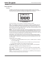
WARNING
AVERTISSEMENT
REMOVE LIFTING EYE
BEFORE WIRING
NOT AN ELECTRICAL
CONNECTION
CAN CAUSE SEVERE INJURY,
DEATH, OR DAM AGE
EQUIPMENT
RETIRER L’OEILLET DE
LEVAGEAVANTDE CÂBLER
PAS UNE CONNEXION
ÉLECTRIQUE
PEUT CAUSER DES BLESSURES
GRAVES, LA M ORT OU DES
DOMM AGES Á L’ÉQUIPEMENT
Figure 3-1: Warning Tag
3-2
For more information visit: www.EatonElectrical.com
MN03902002E
IT. S811 Soft Starter User Manual
October 2004
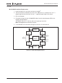
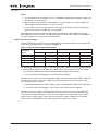
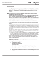
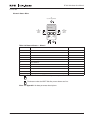
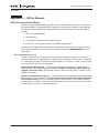
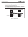
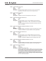
S811V10N3S Installation Requirements
1. Install the device in a minimum enclosure size 30 ft3.
2. Two (2) forced air ventilation fans with a min. 500 ft3/min, at a location for “air in” —
bottom right or left corner and “air out” — opposite upper right or left corner.
3. RD circuit breaker.
4. For power wiring: Use four (4) 500 MCM cables for each phase between RD circuit
breaker and Soft Starter.
OPTIONAL: Two (2) 3" x 1/4" bus with a 1/4" spacer per terminal.
Note: See Figure 3-2 for alternative layouts.
5. Line and load service entrance wiring must not cross in the enclosure.
Line Service
(4) 350
MCM/Terminal
RD
Circuit
Breaker
RD
Circuit
Breaker
(4) 500 MCM or
(2) 3 x 1/4" Bus
with 1/4"
Space/Terminal
12"
Minimum
Distance
S811V10N3S
IT.
Soft Starter
6"
Minimum
Distance
Isolation
Contactor
6"
Minimum
Distance
S811V10N3S
IT.
Soft Starter
Line Service
(4) 350
MCM/Terminal
Figure 3-2: Power Wiring Alternatives
MN03902002E
For more information visit: www.EatonElectrical.com
3-3
IT. S811 Soft Starter User Manual
October 2004
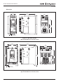
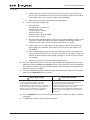
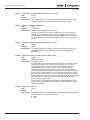
Dimensions
1.97
(50.0)
6.48
(164.5)
6.87
(174.5)
2.66
(67.6)
7.38
(187.4)
5.23
(132.9)
3.46
(88.0)
.22 (5.5)
Typ. 4 Places
Figure 3-3: N Frame (65 mm)
Approximate Dimensions in Inches (mm)
3.54
(90.0)
6.64
(168.7)
4.42
(112.2)
7.92
(201.2)
7.44
(189.0)
5.53
(140.5)
3.49
(88.5)
.27 (6.8)
Typ. 4 Places
Figure 3-4: R Frame (110 mm)
Approximate Dimensions in Inches (mm)
3-4
For more information visit: www.EatonElectrical.com
MN03902002E
IT. S811 Soft Starter User Manual
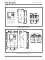
October 2004
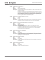
6.39
(162.4)
7.67
(194.8)
11.77
(299.0) 12.71
Slots (322.9)
5.40
(137.2)
2.95
(75.0)
Slots
.28 (7.1)
Slots Typ.
6 Places
5.91
(150.0)
Slots
Figure 3-5: T Frame (200 mm)
Approximate Dimensions in Inches (mm)
7.35
(186.6)
9.84
(250.0)
16.57
(420.8)
15.63
(397.0)
.26 (6.5) Dia.
Typ. 4 Places
15.16
(385.0)
Slots
3.74
(95.0)
11.05
(280.6)
.27 (6.7) Dia.
Typ. 4 Places
Figure 3-6: V Frame (290 mm)
Approximate Dimensions in Inches (mm)
MN03902002E
For more information visit: www.EatonElectrical.com
3-5
IT. S811 Soft Starter User Manual
October 2004
1.83
(46.4)
1.77
(45.0)
.91
(23.2)
.89
(22.5)
.29
(7.5)
3.08
(78.3)
2.91
(74.0)
.31
(8.0)
2.68
(68.0)
.41
(10.5)
.49
(12.5)
Figure 3-7: EMA91 Digital Interface Module
Approximate Dimensions in Inches (mm)
3-6
For more information visit: www.EatonElectrical.com
MN03902002E
IT. S811 Soft Starter User Manual
October 2004
Required Mounting Hardware
Table 3-1: Required Mounting Hardware
Frame
Size
Screw Size
Washer Size
Quantity
Required
Torque
Required
N
#10 – 32 x 0.5
Standard #10 Lockwasher and
Flat Washer
4
15 Lb-in
(1.7 N•m)
R
1/4 – 20 x 0.625
Standard 1/4 Lockwasher and
Flat Washer
4
25 Lb-in
(2.8 N•m)
T
1/4 – 20 x 0.625
Standard 1/4 Lockwasher and
Flat Washer
6
30 Lb-in
(3.4 N•m)
V
1/4 – 20 x 1.5
Grade 8 Allen head
hex cap screws
Quantity: 4
ID: 0.270
OD: 0.495 – 0.505
Max. 0.055 Thick
8
50 Lb-in
(5.6 N•m)
Quantity: 4
Special Washer
Included with V Frame Units
Weight Support Requirements
Table 3-2: Weight Support Requirements
Frame
Size
Weight of Unit
N
5.8 Lbs. (2.6 Kg)
R
10.5 Lbs. (4.8 Kg)
T
48 Lbs. (21.8 Kg) with lugs
V
103 Lbs. (46.8 Kg) with lugs
41 Lbs. (18.6 Kg) without lugs
91 Lbs. (41.4 Kg) without lugs
MN03902002E
For more information visit: www.EatonElectrical.com
3-7
IT. S811 Soft Starter User Manual
October 2004
Power Wiring
Using the wiring diagrams in Figures 3-10, 3-11 and 3-12 and Table 3-3 below as guides,
connect the line, Motor, and Power Supply wiring in accordance with appropriate local and
national codes.
Note: To provide optimum motor protection the Line and Motor power wiring should be
tightly bundled and run perpendicular to the orientation of the S811.
Safety Notices
Danger High Voltage
Danger Haute Tension
Hazard of Burn or Electrical Shock
Risque de Brûlure ou de Choc Electrique
To avoid shock hazard, disconnect all power to the
controller, motor or other control devices before
any work is performed on this equipment. Failure
to do so will result in personal injury, death or
substantial property damage.
Pour éviter des chocs électriques, débrancher
l’alimentation du contrôleur, du moteur ou des
autres appareils de contrôle avant d’y effectuer du
travail. L’inobservation de ces instructions
entraînera des blessures corporelles graves, la mort
ou des dégâts matériels substantiels.
Do not apply a disconnect device on the output of
the S811 unless a means to turn off the soft starter
when disconnect switch is open is utilized.
Opening disconnect while the S811 is operating
may cause a malfunction. Closing disconnect
switch while the S811 is operating will result in a
soft starter failure and potential equipment
damage and personnel hazard.
Ne pas appliquer un appareil de sectionnement sur
la sortie du démarreur progressif S811 à moins
qu’un moyen d’éteindre le démarreur progressif
quand l’interrupteur de sectionnement est ouvert
soit utilisé. Le fait d’ouvrir l’interrupteur de
sectionnement pendant le fonctionnement du
démarreur progressif S811 peut entraîner une
défaillance. Le fait d’éteindre l’interrupteur de
sectionnement pendant le fonctionnement du
démarreur progressif S811 entraînera la défaillance
du démarreur progressif et des dégâts à
l’équipement ou risque au personnel.
Note: Short circuit protection must be applied on the line side of the soft starter.
The S811 is to be wired into the three-phase line feeding the three main motor input leads as
would be done for normal across-the-line starting. It must not be wired internally between
motor windings. Refer to the motor nameplate for correct wiring information for normal
across-the-line operation. Contact Eaton if a special motor wiring requirement exists before
wiring your starter.
By factory default, the S811 is to be connected with an ABC phase rotation on the incoming
power wiring. If the motor turns in the incorrect direction upon energization, exchange two
phases at the motor terminal box or at the output terminals of the soft starter. Changing the
input wiring will cause a voltage phase reversal trip.
If the input phase sequence to the S811 must be ACB, the incoming phase sequence will
need to be changed to ACB. Setting ACB as the incoming phase sequence causes the ABC
incoming phase sequence to cause a voltage phase reversal trip.
IMPORTANT: The reversing contactor must never be switched while the soft starter is
operating. In order to gain the full benefit of the S811 with a reversing contactor, the S811
needs to be OFF when switching the direction. The soft starter settings must account for
catching a motor spinning in the opposite direction upon soft restarts. The time required for
slowing the motor to a stop and then ramping up to speed in the opposite direction adds to the
overall starting time. This will also impact the overload protection setting.
3-8
For more information visit: www.EatonElectrical.com
MN03902002E
IT. S811 Soft Starter User Manual
October 2004
See the Motor/Application Considerations in Appendix E of this manual for information on
typical motor winding configurations.
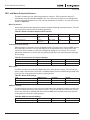
Line and Load power wiring data is shown in Table 3-3.
Table 3-3: Line and Load Power Wiring
Frame
Size
Number of
Lug Kit Options Conductors
N
Supplied
Standard with
Box Lugs
R
Supplied
Standard with
Box Lugs
1
1
Wire Sizes
Cu 75°C
Lug Type Only
Torque
Requirements
Number
of Kits
Required
Box Lug
2 AWG
50 Lb-in (5.6 N•m)
N/A
4 – 6 AWG
45 Lb-in (5.0 N•m)
8 AWG
40 Lb-in (4.5 N•m)
10 – 14 AWG
35 Lb-in (4.0 N•m)
14 – 8 AWG
(2.5 – 10 mm2)
90 – 100 Lb-in
(10.1 – 11.3 N•m)
Box Lug
N/A
6 – 4 AWG
(16 – 25 mm2)
3 – 3/0 AWG
(27 – 95 mm2)
T
V
EML22
2
—
250 Lb-in (28.3 N•m)
4 – 1/0 MCM
(21.2 – 53.5 mm2)
EML23
1
—
4/0 – 500 MCM
(107 – 240 mm2)
250 Lb-in (28.3 N•m)
EML24
2
—
4/0 – 500 MCM
(107 – 240 mm2)
250 Lb-in (28.3 N•m)
EML25
1
—
2/0 – 300 MCM
(70 – 150 mm2)
225 Lb-in (25.5 N•m)
EML26
2
—
2/0 – 300 MCM
(70 – 150 mm2)
225 Lb-in (25.5 N•m)
EML28
2
—
4/0 – 500 MCM
(107 – 240 mm2)
250 Lb-in (28.3 N•m)
EML30
4
—
4/0 – 500 MCM
(107 – 240 mm2)
250 Lb-in (28.3 N•m)
EML32
6 —
4/0 – 500 MCM
(107 – 240 mm2)
250 Lb-in (28.3 N•m)
EML33
4
—
2/0 – 300 MCM
(70 – 150 mm2)
225 Lb-in (25.5 N•m)
2
2
Requires special lug cover. Check with Eaton for availability.
CSA approved 350 MCM – 500 MCM
Lugs for T and V Frame
T and V frame units are supplied standard without lugs. If lugs are needed, they can be
ordered through your local Eaton distributor. Each lug kit contains three lugs, mounting
hardware, and instructions for use on either line or load side of the IT. Soft Starter. Catalog
numbers and wire ranges for lug kits are listed in the table above.
MN03902002E
For more information visit: www.EatonElectrical.com
3-9
IT. S811 Soft Starter User Manual
October 2004
Lug Installation
Danger High Voltage
Danger Haute Tension
Hazard of Burn or Electrical Shock
Make sure all power is off before wiring.
Risque de Brûlure ou de Choc Electrique
Vérifier que toute alimentation est débrancher
avant de câbler.
Note: For additional motor and system protection, a Metal Oxide Varistor (MOV) may be
installed on the line side of the unit. An MOV can also be installed on the load side of
the Soft Starter if additional protection is desired. Generally, it is more common to use
a MOV on the line side. Refer to the instructions provided with the MOV kit.
1. For T and V Frame Soft Starters, remove line and load terminal covers by removing the
screws that hold each cover (and the MOV, if installed) onto the unit.
Note: For N and R Frame Soft Starters, it is not necessary to remove the covers in order
to wire the device. Proceed to step 3.
2. After screws are removed, slide covers off of unit. Set the covers and screws aside.
3. Position lugs and install lug mounting screws according to instructions provided with
the kit. Tighten lug mounting screws provided with the kit to 120 Lb-in (13.6 N•m).
4. Wire the appropriate line and load conductors to the IT. Soft Starter (as required by NEC
and local codes based on the device rating).
5. Torque bolts as directed by Table 3-3 on Page 3-9 of this manual.
Figure 3-8: V Frame Shown with Terminal Cover Removed
and EML30 Lug Kit Installed on Load Side
6. Slide the line and load covers back into place on the soft starter.
7. Reinstall the cover screws through the cover and the MOV, if installed.
8. Insert two outer cover screws through cover.
9. Align cover and torque all cover screws to 5 Lb-in (0.6 N•m). Do not overtighten screws.
3-10
For more information visit: www.EatonElectrical.com
MN03902002E
IT. S811 Soft Starter User Manual
October 2004
Control Wiring Inputs
Control wiring is connected to the S811 by a 12-pin terminal block located at the front of the
unit. Using the wiring diagrams in Figures 3-10, 3-11 and 3-12 and Tables 3-4 and 3-5 as
guides, connect the control wiring as required for your application.
!
Caution
!
Only apply 24V DC to the control terminal block
unless specified otherwise in this manual. All
control wiring is 22 – 12 AWG (0.33 – 2.5 mm2).
Failure to follow this caution could result in severe
damage to the controller.
Attention
Appliquer seulement 24V CC à la barrette à bornes
de commande sauf ce manuel offre d’avis
contraire. Toute la filerie de commande est de
calibre 0.33 – 2.5 mm2 (22 à 12 AWG).
L’inobservation de cet énoncé pourrait entraîner
des dégâts matériels au contrôleur.
Figure 3-9: Terminal Block
Table 3-4 provides the 12-pin terminal block wiring capacity and torque requirements for the
control wiring.
Table 3-4: 12-Pin Terminal Block Wiring Capacity
Number of
Conductors
Torque
Requirements
22 – 14 AWG
(0.33 – 2.5 mm2)
2
3.5 Lb-in (0.4 N•m)
12 AWG
(4.0 mm2)
1
3.5 Lb-in (0.4 N•m)
Wire Size
MN03902002E
For more information visit: www.EatonElectrical.com
3-11
IT. S811 Soft Starter User Manual
October 2004
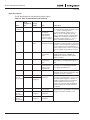
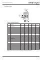
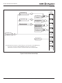
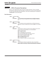
Input Descriptions
The IT. Soft Starter has the following control inputs:
Table 3-5: S811 Terminal Block Control Wiring
Name
Circuit
Common
Power
Terminal
Block
Designation Factory
(Pin)
Default
Input
-
—
Negative
NO Deenergized
3 Amps, @ 120V
AC/24V DC
+
Permissive P
Input 1
1
Input 2
2
Input 3
3
Input 4
4
Relay1
13
Form A
14
NO Contact
Form C
95
Common
Relay2
96
Form C
NC Contact
Relay2
98
Form C
NO Contact
3-12
Connections
Power supply connections:
– Connect power supply negative to pin
“–” and to system ground
—
24V DC nominal
– Connect +24V DC output to pin “+”
(see 24V DC
Note: To avoid voltage drop during
Power Supply
bypass contactor inrush, a minimum of
Requirements
section for sizing 14 AWG wire should be used between
of power supply) the power supply and the “+” and “–”
inputs at the S811 terminal block.
Hardwired
24V DC only
Pin “P”, permissive, must be energized
STOP
(maintained input) (+24V DC) to enable operation of the unit.
If power is removed from the permissive
circuit at any time, the unit will begin a
STOP command. If a soft stop is selected,
the soft stop will begin and run to timeout.
START
24V DC only
Applying 24V DC to Input 1 while P is
(momentary
energized will initiate a START. As
input)
shipped from the factory this input is
“level” sensitive.
JOG
24V DC only
Input 2 is JOG. Applying 24V DC to this
(momentary
input while P is energized will initiate a
input)
JOG.
HAND/AUTO 24V DC only Must Input 3 is HAND. Hand must be energized
be maintained for
to enable control (START/STOP/JOG)
control from the
through the terminal block.
terminal block
Fault RESET 24V DC only
Input 4 is Fault RESET. Energizing this
input will reset a fault only after the fault
condition has been corrected.
Common
3 Amps, @ 120V
NO Form A contact: As shipped from the
AC/24V DC
factory this programmable contact closes
NO Dewhen the starter’s bypass contactor is
energized
energized. It will remain closed until a
STOP is initiated. The motor may
continue to run even after the STOP is
initiated until the stop ramp has been
completed.
Common
Form C Common Form C contacts: As shipped from the
for 96 and 98
factory these programmable contacts will
change status when a Fault occurs.
NC De3 Amps, @ 120V
energized
AC/24V DC
For more information visit: www.EatonElectrical.com
MN03902002E
IT. S811 Soft Starter User Manual
October 2004
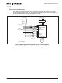
Typical Control Wiring Diagrams
Each diagram illustrates a typical wiring scheme for the options described. The terminal
block represents the soft starter. The additional Cutler-Hammer items shown on the diagrams
are not included, but they may be purchased from Eaton.
Incoming Lines
1
2
3
Power Supply
Disconnect
24V DC
+
(See Note 1)
* E-Stop
Stop
(See Note 3)
Jumper
+24V to 3
**
–
Start
Jog
Reset
In Bypass
Ready
Fault
–
+
P
1
2
3
4
13
14
95
96
98
L1/1 L2/3 L3/5
24V DC Power
S811 Soft Starter
Inputs
24V DC Only
Internal
Contacts
T1/2 T2/4 T3/6
Optional 24V DC
Pilot Lights
(See Note 2)
Motor
* E-Stop Maintained
** As Required per National and Local Electric Codes
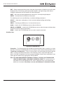
Figure 3-10: Basic Connection Diagram for 24V DC 3-Wire Pushbutton
STOP/START/JOG/RESET and 24V DC Fault/Ready and Bypass Indication
MN03902002E
For more information visit: www.EatonElectrical.com
3-13
IT. S811 Soft Starter User Manual
October 2004
Incoming Lines
1
2
3
Power Supply
Disconnect
**
24V DC
+
–
(See Note 1)
* E-Stop
Jumper
Hand
OFF
Auto
Remote
(See Note 3) Contact
Jumper
+24V to 3
Reset
In Bypass
Ready
Fault
–
+
P
1
2
3
4
13
14
95
96
98
L1/1 L2/3 L3/5
24V DC Power
S811 Soft Starter
Inputs
24V DC Only
Internal
Contacts
T1/2 T2/4 T3/6
Optional 24V DC
Pilot Lights
(See Note 2)
Motor
* E-Stop Maintained
** As Required per National and Local Electric Codes
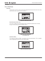
Figure 3-11: Basic Connection Diagram for 24V DC 2-Wire Switch HAND/OFF/AUTO/RESET
and 24V DC Fault/Ready and Bypass Indication
Incoming Lines
1
2
3
Power Supply
Disconnect
24V DC
+
**
–
(See Note 1)
* E-Stop
Jumper
+24V to P
–
+
P
1
2
3
4
13
14
95
96
98
L1/1 L2/3 L3/5
24V DC Power
S811 Soft Starter
Inputs
24V DC Only
Internal
Contacts
T1/2 T2/4 T3/6
Motor
* E-Stop Maintained
** As Required per National and Local Electric Codes
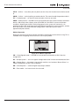
Figure 3-12: Basic Connection Diagram for Use of DIM Control Only
3-14
For more information visit: www.EatonElectrical.com
MN03902002E
IT. S811 Soft Starter User Manual
October 2004
Notes:
1. A minimum of wire of 14 AWG (2.5 mm2) should be used between the power supply and
the 24V DC + and - terminals.
2. See Using an Auxiliary Relay section below if it is desired to use a relay instead of an
indicating lamp for terminals 13, 14, 95, 96 and 98.
3. If an isolation or reversing contactor is used upstream of the S811, Eaton recommends
that the user choose the edge level sensing option.
Each diagram illustrates a typical wiring scheme for the options described. The terminal
block represents the soft starter. The additional Cutler-Hammer items shown on the diagrams
are not included, but can be purchased from Eaton.
24V DC Control Power Supply
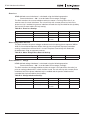
The S811 Soft Starter requires 24V DC control power. The sealed in and inrush characteristics
of the S811 Soft Starter are summarized in Table 3-6:
Table 3-6: 24V DC Power Supply Requirements
Soft Starter
Frame
Sealed
Inrush
Watts
Amps
Watts
Amps
Duration (ms)
S811N
25
1.0
240
10
150
S811R
25
1.0
240
10
150
S811T
25
1.0
240
10
150
S811V
25
1.4
240
10
150
For applications where one starter is used with one power supply, the power supply selected
must be equal to or greater than both the sealed in and inrush requirements of the starter.
●
Max Steady State for the Power Supply ≥ Sealed In Power of the Starter
●
Outrush for the Power Supply ≥ Inrush Power of the Starter
Multiple starters can be used with one power supply. If the application requires the starters to
start at the same time, the power supply must be sized for the sum of the sealed in and
inrush power for each starter.
●
Max Steady State for the Power Supply ≥ Sum of the Sealed In Power of all the Starters
●
Outrush for the Power Supply ≥ Sum of the Inrush Power of all the Starters
Multiple starters are typically not commanded to start at the same time. If the application
requires the starters not be commanded to start at the same time (>150 ms between start
commands), the required power is the sum of the largest inrush power, plus the sealed in
power of the running starters. Worst case from a power supply standpoint is the largest
inrush starter commanded to start while all the other starters are running.
MN03902002E
For more information visit: www.EatonElectrical.com
3-15
IT. S811 Soft Starter User Manual
October 2004
Formulas to calculate power supply requirements are as follows:
●
Definitions:
SI = Sum of Seal Incurrent
LS = Largest Seal Incurrent
LI = Largest Inrush Needed
TS = Total Seal Incurrent Needed
LO = Largest Outrush Needed
TS = (SI - LS)
LO = TS + LI
●
Max Steady State for the Power Supply ≥ SI
●
Outrush for the Power Supply ≥ LO
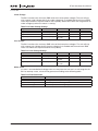
The voltage on the S811 + and – control terminals must not exceed 30V DC to prevent
hardware damage. The S811 will shut down and issue low control voltage fault at control
voltages less than 17V DC. The fault will reset at control voltages greater than 18V DC. The
Cutler-Hammer control power supplies listed in Table 3-7 are recommended.
Table 3-7: 24V DC Power Supplies
Catalog
Number
Continuous
Watts
Peak
Amps
Input Voltage
VAC
Amps
PSS55A
55
2.3
10.0
90 – 140
PSS55B
55
2.3
10.0
180 – 260
PSS55C
55
2.3
10.0
360 – 500
PSS160E
160
6.5
13.0
90 – 260
PSS160C
160
6.5
13.0
360 – 500
PSS300E
300
12.5
20.0
90 – 260
PSS600C
600
25.0
50.0
360 – 500
Control Wiring Application Notes
!
Caution
Only apply 24V DC to the terminal block unless
specified otherwise in this manual. All control
wiring is 22 – 12 AWG (0.33 – 2.5 mm2). Failure to
follow this caution could result in severe damage
to the controller.
!
Attention
Appliquer une tension de 24 V c.c. aux bornes sauf
avis contraire dans ce manuel. Toute la filerie de
commande est de calibre 0.33 – 2.5mm2 (22 à 12
AWG). L’inobservation de cette mesure pourrait
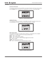
causer des dommages importants au contrôleur.
1. Connect DC common (negative) to terminal -, using a minimum wire of 14 AWG (2.5 mm2).
2. Connect +24V DC positive to terminal +, using a minimum wire of 14 AWG (2.5 mm2).
3. Terminal P (permissive circuit) — Must be energized at +24V DC to enable operation of
all S811 soft starters. For all units, if power is removed from the permissive circuit at any
time, the unit will initiate a stop sequence, including a soft-stop if enabled.
Note: With level sensing control, if +24V DC is removed from the permissive circuit at
any time, the unit will initiate a stop and restart when +24V DC is reapplied to
terminal P if:
3-16
For more information visit: www.EatonElectrical.com
MN03902002E
IT. S811 Soft Starter User Manual
October 2004
a) +24V DC is still available on pin 1 (to start from Terminal Block, Input #3 must
also be enabled),
b) the device shows a green status light (not faulted), and
c) the Reset Mode parameter is set to AUTO on Digital Interface Module (DIM).
See the Edge and Level Sensing sections below for more details. If the AUTO
setting is used, CAUTION must be exercised to assure that any restart occurs in a
safe manner.
4. Terminal 1 (Start mode) — If terminal P is at +24V DC, momentary application of +24V
DC to terminal 1 will initiate a start sequence for all S811 soft starters.
Note: With level sensing control, if +24V DC is maintained on terminal 1 (Start) and
removed from the permissive circuit at any time, the unit will initiate a stop. The
unit will restart on application of +24V DC to terminal P if:
a) +24V DC is still available on pin 1 (to start from Terminal Block, Input #3 must
also be enabled),
b) the device shows a green status light (not faulted), and
c) the Reset Mode parameter is set to AUTO on Digital Interface Module (DIM).
See the Edge and Level Sensing sections below for more details. If the AUTO
setting is used, CAUTION must be exercised to assure that any restart occurs in a
safe manner.
Edge Sensing
Edge sensing is set with the Start Control parameter.
Edge sensing requires +24V DC power be momentarily applied to pin 1 (with terminal P
at +24V DC) to initiate a start under all conditions. After a stop or fault occurs, the +24V
DC must be removed, then reapplied to pin 1 before another start can occur. This control
configuration should be used when restarting of the motor after a fault or stop must be
supervised manually or as a part of a control scheme. The cycling of +24V DC power to
terminal 1 before starting is required regardless of the setting of the Reset Mode
parameter.
Level Sensing
Level sensing is set with the Start Control parameter.
Level sensing will enable a motor to restart after a fault is cleared without cycling
+24V DC power to terminal 1 as long as:
MN03902002E
●
Terminal P is supplied with +24V DC (to start from Terminal Block, Input #3 must
also be enabled),
●
The Reset Mode parameter is set to AUTO,
●
All faults have been reset.
For more information visit: www.EatonElectrical.com
3-17
IT. S811 Soft Starter User Manual
October 2004
This control configuration should be used where it is desirable to restart a motor after a
fault without additional manual or automatic control. An example of this condition
would be on a remote pumping station where it is desirable to automatically restart a
pump after a power outage without operator intervention.
In the AUTO RESET MODE, CAUTION must be exercised to assure that any restart
occurs in a safe manner.
5. Terminal 2 (Jog mode) — If +24V DC power is applied to this terminal while terminal P is
at +24V DC, the soft starter will operate in the jog mode as long as +24V DC is on
terminal 2 and no faults occur. In jog mode, the soft starter will operate only on the
thyristors and the bypass contactors will not close.
6. Terminal 3 (HAND/AUTO setting) — Choose setting using the Reset Mode parameter on
the DIM.
7. Terminal 4 (Reset) — Application of +24V DC power will reset the soft starter after all
fault conditions are cleared. If the AUTO setting is used with level control CAUTION
must be exercised to assure that any restart occurs in a safe manner. See Edge and
Level sensing on Page 3-17.
8. Terminals 13 and 14 (Programmable) — At default setting, relay contacts for use up to
120V AC or 24V DC provide bypass contactor status. The contact closes upon bypass
and will remain closed until a stop is initiated or a fault occurs. The motor and load may
continue to rotate after a stop is initiated if soft stop is being used or if the load inertia is
high. See Using an Auxiliary Relay section below for additional contact interface
information.
9. Terminals 95, 96 and 98 (Programmable) — At default setting, relay contacts for use up
to 120V AC or 24V DC provide fault or ready status indication. See Page 3-12 for a
description of their operation.
Connecting a New or Replacement DIM
When 24V DC is first applied to terminals + and -, the S811 will send commands to the DIM to
reconfigure its communication, and the S811 will send a reset to the DIM after configuration
is done (this process takes approximately 20 seconds).
Using an Auxiliary Relay
The IT. Soft Starter contains one Form A and one Form C set of auxiliary contacts to indicate
its status. A contact between terminals 13 and 14 indicates when the IT. is in bypass (unless it
has been programmed to indicate another status). The contacts between terminals 95 and 96
and 95 and 98 indicate the IT. is in a normal or tripped state (unless it has been programmed
to indicate another status). Often these contacts are used as shown in Figures 3-10, 3-11 and
3-12 with indicating lamps. In some installations the user may wish to use an
electromagnetic relay for indication of the status at a remote location for use by a
programmable controller (PLC), or in a 120V AC or 24V DC control circuit.
If the IT. Soft Starter is subject to mechanical shock during operation, it is possible that these
contacts may momentarily open, causing nuisance fault tripping of down stream devices.
When used with an indicating lamp, a momentary contact opening would not be observed. In
order to assure proper application, it is suggested that the following recommendations be
followed:
3-18
For more information visit: www.EatonElectrical.com
MN03902002E
IT. S811 Soft Starter User Manual
October 2004
PLC Interface — It is suggested that a 20 mS delay be programmed to assure the contact
status before a change of status is indicated. The application and the environmental issues
will determine the exact requirements.
24V DC Control — When a relay is used in conjunction with an electronic control, it is highly
recommended that a noise suppression/snubber diode be placed across the relay coil as
shown in Figure 3-13. This diode offers two benefits. First, the suppression of any electrical
noise generated when the relay coil is de-energized. Second, the diode delays the opening of
the relay slightly as it dissipates the energy stored in the relay coil. This delay is often long
enough to compensate for the potential effects of a mechanical shock opening the control
contact. A typical suppression diode is a 1N4001.
13
Bypass
R
+
14
95
24V DC
Supply
Ready
–
R
96
R
98
Fault
Figure 3-13: 24V DC Control
120V AC Control — When a relay is used in conjunction with an electronic control, it is highly
recommended that a noise suppressor be used across the relay coil. In the case of an AC coil,
the noise suppressor is made up of a series connected resistor and capacitor as shown in
Figure 3-14. Usually the delay in the relay opening is very small, so if the system is subject to
shock, a delay should be added in the external control before the contact change of state is
recognized. The resistor is rated 100 ohms at 0.5 watts. The capacitor is 0.25 µF at 250V AC.
13
Bypass
R
+
14
95
120V AC
Supply
Ready
–
R
96
R
98
Fault
Figure 3-14: 120V AC Control
Using a Supplemental Line Contactor
In some installations, it may be necessary to use an electromagnetic contactor in series with
the soft starter. In this case, it is recommended that the contactor be placed on the load side
of the soft starter. The contactor must be closed prior to starting the soft starter and remain
closed until the Soft Starter has been stopped to ensure proper soft starter and system
operation.
MN03902002E
For more information visit: www.EatonElectrical.com
3-19
IT. S811 Soft Starter User Manual
October 2004
If an electromagnetic contactor is used on the line side of the soft starter, additional control
circuitry must be supplied by the user when using edge level control to ensure the line power
is supplied to the soft starter before control power (24V DC) is applied. If this sequence is not
followed, the soft starter will fault on either a phase loss or zero voltage-crossing fault. This
control scheme is illustrated in Figure 3-15.
START
STOP
120V AC
X
T
X
(Side Adder #1)
Soft-Starter
24V
PP
24V DC
T
(On Delay -6 Seconds)
X
(Isolation Contactor)
1
AutoReset = ON
L1
480V AC
Mains
L2
L3
Figure 3-15: 24V DC Control with Edge Sensing
If it is desired to place an electromagnetic contactor on the line side of the soft starter, when
using level control, no additional control circuitry is required. A start can be completed when
the line power is supplied to the unit after the control power (24V DC), providing the Reset
Mode parameter is set to AUTO and the unit has a green light status with +24V DC on pin 1.
The soft starter will not fault on either a phase loss or zero voltage-crossing faults.
If the AUTO setting is used, CAUTION must be exercised to assure that any restart occurs in
the safe manner.
3-20
For more information visit: www.EatonElectrical.com
MN03902002E
IT. S811 Soft Starter User Manual
November 2004
Chapter 4 — Specifications
Environmental
Table 4-1: Environmental Specifications
Item
Specification
Temperature Range —
Operating
Storage
-40°F – 122°F (-40°C – 50°C)
-58°F – 158°F (-50°C – 70°C)
Elevation
Up to 6,600 ft. (2000m). Above
6,600 ft. (2000m), derate 0.5% per
330 ft. (100m)
Humidity
Functional to 95% non-condensing
Operating Orientation
Any
Pollution Degree IEC 60947-1
3
Shock Resistance
15g in any direction
Vibration Resistance
3g in any direction
Physical
Table 4-2: Weight
Frame
Size
Weight of Unit
N
5.8 Lbs. (2.6 Kg)
R
10.5 Lbs. (4.8 Kg)
T
48 Lbs. (21.8 Kg) with lugs
41 Lbs. (18.6 Kg) without lugs
V
103 Lbs. (46.8 Kg) with lugs
91 Lbs. (41.4 Kg) without lugs
Table 4-3: Agency Standards and Certifications
MN03902002E
Standard
Certifications
UL
UL 508
CSA
CSA 22.2 – 14 – 1995
IEC
60947-4-2
CE
See Table 4-4
For more information visit: www.EatonElectrical.com
4-1
IT. S811 Soft Starter User Manual
November 2004
CE Conformance
Table 4-4: EMC Immunity
Immunity
Severity Level
Electrostatic Discharge
IEC 61000-4-2
4 kV contact discharge
8 kV air discharge
Electromagnetic Field
IEC 61000-4-3
10 V/m
80 – 1000 MHz
2 angles
Fast Transient Bursts
IEC 61000-4-4
2 kV, 5 kHz rep, 2 min intervals
1.2/50 µS – 8/20 µS Surges
IEC 61000-4-5
2 kV Line to earth
1 kV Line to Line
1 minute intervals
Conducted RF
IEC 61000-4-6
10 V rms
.15 – 80 MHz
50 Hz Magnetic Field
IEC 61000-4-8
N/A
Voltage dips
Interrupt
IEC 61000-4-11
30 % dip @10 mS
60 % dip @100 mS
100% interrupt @5 S
Emmissions
Radiated
EN 55011, Class A
Conducted
EN 55011, Class A
1. The 24V DC power supply must be grounded.
2. Add ferrite, Fair-Rite #0444173551 to DC Power Leads and Control I/O Leads (all through
one ferrite) at S811 with two passes through ferrite of the DC Power Leads, and a single
pass through ferrite of the I/O Control Leads.
3. Add ferrite, Fair-Rite #0443167251 to Load Leads at S811 with two passes through
ferrite.
4-2
For more information visit: www.EatonElectrical.com
MN03902002E
IT. S811 Soft Starter User Manual
November 2004
Short Circuit Ratings
Table 4-5: Short Circuit Ratings
Soft Starter
Frame Size
Three-Phase Short Circuit Rating
240V
480V
600V
690V
N
10 kA
10 kA
10 kA
—
R
10 kA
10 kA
10 kA
—
T
18 kA
18 kA
18 kA
V
42 kA
42 kA
42 kA
Catalog No. S811T__V3S devices are UL Listed and suitable for use on a circuit
capable of delivering not more than 18 kA symmetrical amperes, 690 volts
maximum, when protected by a Ferraz-Shawmut Amp-Trap Form 101 (Cat. No.
A70QS800-4) 800 Amp, 700 Volt Semiconductor Protection Fuse.
Catalog No. S811V__V3S devices are UL Listed and suitable for use on a circuit
capable of delivering not more than 42 kA 690 volts maximum, when protected by
a Ferraz-Shawmut Type PSC (Cat. No. A070URD73I1600) 1600 Amp, 700 Volt
Semiconductor Protection Fuse.
Catalog No. S811T__V3S devices tested per IEC 60947-4-2 to Type 1 Short Circuit
Withstand Requirements to 18 kA, 690 volts with Cutler-Hammer Cat. No.
NW3800T33W 800 Amp 690 Volt circuit breaker.
Catalog No. S811V__V3S devices tested per IEC 60947-4-2 to Type 1 Short Circuit
Withstand Requirements to 42 kA, 690 volts with Cutler-Hammer Cat. No.
RW420T33W 2 kA 690 Volt circuit breaker.
Note: Short circuit protection must be applied on the line side of the soft starter.
MN03902002E
For more information visit: www.EatonElectrical.com
4-3
IT. S811 Soft Starter User Manual
November 2004
4-4
For more information visit: www.EatonElectrical.com
MN03902002E
IT. S811 Soft Starter User Manual
November 2004
Chapter 5 — Functional Description
Power
The S811 Soft Starter controls the voltage applied to a three-phase induction motor in order
to control the starting torque and provide a smooth starting characteristic. Within the soft
starter are three power poles, each of which includes a set of anti-parallel SCRs (thyristors) in
parallel with a contact. During a start, the conduction periods of the SCRs are continuously
adjusted to apply a gradually increasing voltage to the motor, resulting in gradually
increasing torque and a smooth start. As the motor reaches its rated speed, the power pole
contacts are closed, bypassing the SCRs for the most efficient operation.
3-Phase
AC Line
Voltage
L3
T3
L2
T2
L1
T1
Motor
Figure 5-1: Soft Starter SCRs
For each start, the length of time the SCRs are conducting current as well as the magnitude of
that current determine how hot the SCRs will get. Between successive starts the SCRs must
cool down to avoid exceeding their thermal limits. Appendix D (Ratings, Cooling and Power
Losses) gives the S811’s application ratings for various starting conditions. Staying within
these specified limits should avoid over temperature trips.
When the S811 control circuit senses that the internal temperature has increased above a
preset value, internal fans are tuned on to assist in cooling. To maximize fan life the fans are
only turned on when needed. Further discussion of fan operation can be found in Appendix D.
Control
The software contained in the S811 IT. Soft Starter is the heart of the product. This software
allows you to control nearly every aspect of the soft starter’s functionality. In this section,
various features and protection options are described.
Note: In the following descriptions the S811 Parameter Names are shown in italics. You will
find a complete listing of these parameters in Appendix A.
Note that the motor current measurements made with a standard meter may not be correct
because of the non-sinusoidal nature of the current during starting. The S811 is designed to
accurately measure these currents so that the current displayed by the S811’s Digital
Interface Module (DIM) is correct.
MN03902002E
For more information visit: www.EatonElectrical.com
5-1
IT. S811 Soft Starter User Manual
November 2004
Starting Options
The following starting choices are available in the S811 IT. Soft Starter:
Voltage Ramp Start
This is the most commonly used mode of soft starting. Starting at an initial value set by the
Initial Torque parameter, the voltage applied to the motor is gradually increased at a rate that
will reach rated voltage at time tr, set by the Soft Start Time parameter. As the voltage
increases the motor develops torque that accelerates the load toward full speed. When the
S811 senses that the motor has come up to speed, it quickly completes the voltage ramp and
closes the bypass contactor. See Figure 5-2.
It should be noted that a lightly loaded motor takes less torque, and thus lower voltage and
time, to accelerate to full speed. For this case the S811 will go into bypass before the ramp
reaches full voltage. In other words, the S811 will go into bypass before the Soft Start Time
has elapsed.
Bypass
Kick
Start
Torq
Initial
Torque
Bypass
Rated
Voltage
100%
100%
Speed
Torque
Voltage
Ramp
Soft Start Time
tr
Kick Start Time
Start
Run
Time (Seconds)
Start
Run
Time (Seconds)
Figure 5-2: Ramp Start
Kick Start — The Kick Start feature works in both the Voltage Ramp Start and Current Limit
Start modes. By momentarily applying a pulse of current to the motor, it provides an initial
boost in torque to overcome the static friction common in some applications. The level of
torque boost is set by the Kick Start Torq parameter and the duration of the “kick” is set by
the Kick Start Time. Setting the Kick Start Time to 0 disables this feature.
5-2
For more information visit: www.EatonElectrical.com
MN03902002E
IT. S811 Soft Starter User Manual
November 2004
Current Limit Start
This mode is typically used when it is necessary to limit the maximum current during start-up
due to line power limitations or other considerations. During a Current Limit Start the S811
applies a constant voltage to the motor, resulting in limited current flowing through the
motor’s windings. The level of current is set by the Initial Torque parameter. See Figure 5-3.
Note: Current Limit Starts are not recommended on variable torque load applications like
fans and pumps.
Bypass
Bypass
Kick
Start
Torq
100%
Speed
Current
Initial
Torque
100%
Soft Start Time
Kick Start Time
Start
Run
Time (Seconds)
Start
Run
Time (Seconds)
Figure 5-3: Current Limit Start
Soft Stop — This feature is used for applications that require a controlled extended stop. It is
designed for high frictional loads that tend to stop suddenly when voltage to the motor is
removed. During Soft Stop the voltage is gradually reduced to zero in the time set by the Soft
Stop Time parameter. See Figure 5-4.
Note: The Soft Stop mode is not an electronic brake function and will not stop a motor any
faster than it would normally take to coast to a stop under load.
Coast to Stop
(Speed)
100%
Speed
Soft Stop Ramp
(Voltage)
Soft
Stop Time
Run
Soft Stop
Time (Seconds)
Figure 5-4: Soft Stop
Pump Start/Stop (Optional) — This pump control option is described in Appendix F.
MN03902002E
For more information visit: www.EatonElectrical.com
5-3
IT. S811 Soft Starter User Manual
November 2004
Protection
Thermal Overload
The IT. S811 Soft Starter features an electronic motor overload protection feature. It is
designed to protect the motor and power wiring against overheating caused by operating at
excessive current levels for extended periods of time.
Entering the motor’s full load current rating, using the Overld Trip FLA parameter programs
the overload. The Overld Trip FLA is settable from 32% to 100% of the S811’s rated current.
The overload’s trip class is set using the Ovrld Trip Class parameter.
Additional details on the Thermal Overload can be found in Appendix B.
S811 and Motor Protection
In addition to motor overload protection, the S811 has many programmable features
designed to protect the motor as well as the soft starter itself.
●
Incoming Line Phase Reversal, Loss, Imbalance, Over Voltage, and Under Voltage trips
●
Three Overcurrent trips
●
Stall and Jam trips
For troubleshooting purpose trips are recorded, as they occur, in the S811’s Fault Queue.
QCPort Network Control
The S811 has two QCPort communications ports, Local (CH1) and Remote Network (CH0).
Local Control (HAND)
Normally for S811 stand-alone operating only one DIM and/or the S811’s terminal block
provide control inputs. However, one or more DIMs, QCPort Cover Controls, as well as other
QCPort devices can be connected to the Local Port and used as input devices to control the
operation of the S811. Each device sends a Motor Control byte to the S811 which logically
combines them and responds appropriately.
Remote Network (AUTO)
The S811 is in the Auto mode when all local devices have relinquished local control. In the
Auto mode, the S811 responds to control commands from the Remote Network. Typically an
industrial automation fieldbus is connected to the Remote Network port via one of the many
network adapters (gateways) available from Eaton.
For further discussion of the network ports, refer to Appendix H.
5-4
For more information visit: www.EatonElectrical.com
MN03902002E
IT. S811 Soft Starter User Manual
November 2004
Chapter 6 — Configuration
Programming the S811
A Digital Interface Module (DIM) is used to configure all models of the IT. S811 Soft Starter.
●
The Status Bar at the top of the display indicates the operating and communicating
status of the S811 and DIM.
●
The three Soft Key Functions at the bottom of the display indicate the functions of the
Soft Keys (pushbuttons) directly below them. The Soft Key Functions will change as
you navigate through the different menus of the DIM.
●
The center of the display shows the value of the selected S811 parameter. The default
display at power-up is “3 ø Line Currents”.
●
Figure 6-1 show how the S811’s parameters are organized within the menu structure.
Navigating through the menus down to the parameters is straightforward if you
understand a few basic concepts.
1. The Escape Key (ESC) moves you from the User Display to the Parameter Edit
Screen.
2. The PREV and NEXT soft keys (Figure 6-2) scroll from menu to menu (left and
right).
3. The far right soft key will allow you to take action (Enter, Edit, More, Send, …) to
“drill down” into the menu or parameter.
4. When you enter a menu, the Previous and Next soft keys scroll from parameter to
parameter (up and down) in that menu.
5. The Escape Key backs you out of the current parameter or menu.
ONLN SS OXFDO1 H STOP
3 Line Currents
XXXX
L1 Amp
XXXX
L1 Amp
XXXX
L1 Amp
JOG
RESET
H->A
Status Bar
Soft Key Functions
Soft Keys
Predefined Keys
ESC
Figure 6-1: Digital Interface Module (DIM) — Display Mode
MN03902002E
For more information visit: www.EatonElectrical.com
6-1
IT. S811 Soft Starter User Manual
November 2004
Status Bar
ONLN SS OXFDO1 H STOP
Monitoring
PREV
NEXT
Soft Key Functions
ENTER
Soft Keys
Predefined Keys
ESC
Figure 6-2: Digital Interface Module (DIM) — Parameter Edit Mode
For a more complete description of the DIM, refer to Appendix G.
S801 to S811 Comparison
If you are familiar with the adjustments of the S801 Soft Starter, Table 6-1 provides you with
a cross-reference between the CIM potentiometer and switch adjustments and the
corresponding S811 parameters found in the Configuration and Protection menus of the
S811’s Digital Interface Module (DIM).
Table 6-1: S801 to S811 Setup Cross-Reference
Description
S801 CIM
S811 DIM
Parameter
Units
Comment
Configuration Menu
Overload
setting
6-2
FLA
Overld Trip FLA Amps
Set for motor’s nameplate rated
current assuming a 1.15 Service
Factor motor. See Appendix D for
other Service Factor motors.
5, 10, 20 and 30
OL Trip Class
Trip Class
Ovrld Trip Class
Kick Start
Torque
T1
Kick Start Torq
% rated torque
Sets the initial breakaway torque to
overcome static friction loads.
Kick Start Time tk
Kick Start Time Sec
Sets the duration of the Kick Start
Initial Voltage
Ramp Torque
T2
Initial Torque
% rated pullout torque
Sets the initial voltage (torque) of the
Voltage Ramp Start.
Current Limit
Torque
T2
Initial Torque
% rated pullout current
Sets the constant current (torque)
applied to the motor throughout its
acceleration to full speed.
Voltage Start
Ramp Time
tr
Soft Start Time Sec
For more information visit: www.EatonElectrical.com
Sets the time to ramp up to rated
voltage (torque). If the motor is not
up to speed at the end of the ramp,
the S811 will trip on a Stall Fault.
Note: Lightly loaded motors will
reach full speed, and the bypass
contactor will close, before tr
elapses.
MN03902002E
IT. S811 Soft Starter User Manual
November 2004
Table 6-1: S801 to S811 Setup Cross-Reference, continued
Description
S801 CIM
S811 DIM
Parameter
Units
Comment
Configuration Menu, continued
Current Limit
Start Time
tr
Soft Start Time Sec
Sets the time at which the S811
expects the motor to be up to speed.
When tr elapses the S811 checks for
a stall condition.
Stop Ramp
Time
ts
Soft Stop Time Sec
Sets the time to linearly ramp down
from rated voltage to zero. The rate at
which the motor slows is dependent
on the load. Not functional on S811s
with Pump Option unless start
method is Pump Start.
Pump Stop
Time (option)
ts
Pump Stop
Time
Sets the time to ramp down the
speed of the motor to zero. Not
functional on standard S811s.
Sec
Protections Menu
Overload
Overload
Ovld Fault
Jam
Jam
Jam Fault
Stall
Stall
Stall Fault
Phase Loss
Ph. Loss
Phase Loss
Fault
Phase
Imbalance
—
Phase Imb
Fault
Phase
Sequence
Reversal
Ph. Rev
Phase Rev Fault
Fault Reset
Man/Auto
Reset
Reset Mode
See also Phase Sequence
Special
Function
Ramp / Current Ramp Start
Limit Start
Start Method
Option — Configuration Menu
MN03902002E
Option
S811 DIM
parameter
Default
Edge/Level
Start Input
Start Control
Level
For more information visit: www.EatonElectrical.com
Sets whether the Start input at the
terminal block responds only when it
sees a transition from 0 to +24V DC
(edge) or anytime 24V DC is present
(level)
6-3
IT. S811 Soft Starter User Manual
November 2004
6-4
For more information visit: www.EatonElectrical.com
MN03902002E
IT. S811 Soft Starter User Manual
November 2004
Chapter 7 — Setup and Starting
Before You Begin
Be Aware of the Following:
1. Terminal P must have 24V DC applied to ENABLE starts.
2. The P and Hand inputs must be energized (24V DC) to enable starting of the Soft Starter
from the terminal block.
3. To Start: Apply 24V DC to Input 1 while the P input is energized.
4. To initiate a Stop remove the P input.
5. For 2-wire control, jumper P and Input 1 together.
6. HAND/AUTO setting (for Terminal 3) must be chosen using the Reset Mode parameter
on the DIM.
7. After an Overload Trip, the S811 Soft Starter cannot be restarted until the prescribed
cool-down time has elapsed. Cycling power does not reset the timer. If 24V DC power is
removed, the soft starter will remember the remaining time and will resume the cooldown timing when power is again reapplied.
8. On frames R, V and T when the S811 goes into bypass, a sound similar to contactor
chatter can be heard. This sound is the result of multiple contactors closing one after the
other in a very short period. It is normal operation intended to reduce the surge current
requirements of your power supply.
9. To Jog: apply 24V DC to input 2, (terminal P must also have 24V applied). To stop
remove 24V DC from input 2.
10. In jog, the unit will follow the normal start ramp as long as terminal 2 is at 24V DC.
11. Jog operates the same as a normal start, except that the bypass contactors will not
close and the soft stop is not functional.
12. Jog is only intended for short term jogging of the motor and not for long term
two-wire control.
Setup
After all power and control connections have been made and you have read and understood
the different operating modes and protection features (Chapter 5) of the soft starter, it is time
to program it for your application. The following procedure will take you through the setup of
the S811 to match it to your motor and application, “bumping” the motor to verify correct
direction of rotation, and tuning of the selected operating mode. After this procedure has
been completed, it is suggested that you review the Protection Options of the S811
(Appendix B) and select the appropriate ones for your application. All Protection Options are
shipped from the factory “enabled”.
As shipped from the factory, the S811 Soft Starter’s default configuration is sufficient for
basic operation but may require some configuration to “tune” it for your application. The
following procedure assumes you understand how to “navigate” through the S811’s
parameter menu using the Digital Interface Module (DIM) and that the S811 is in its Factory
(Out-of-Box) state. Refer to Appendix G of this manual for a detailed explanation of DIM
operation.
MN03902002E
For more information visit: www.EatonElectrical.com
7-1
IT. S811 Soft Starter User Manual
November 2004
Initial Configuration:
1. It is suggested that the S811 Soft Starter be configured before applying the line voltage.
Before applying the Line voltage, apply 24V DC to the + and - connections of the S811’s
terminal block. “Eaton Cutler-Hammer” will be displayed by the DIM while the S811 is
powering up. When power-up is complete the DIM should be displaying “3 Ø Line
Currents”.
Note: If anything else is displayed, go to Chapter 8, Troubleshooting, for information on
getting the S811 back to a known state.
2. Using the DIM, review the parameter settings in the “Configuration” and “Protections”
menus. Parameter navigation and menus are located in Appendix A and G. The
following setup procedures will use the factory default settings unless changed by you.
3. In the Configuration menu, set the Overld Trip FLA parameter to the motor’s nameplate
rated current. This setting assumes the motor has a 1.15 Service Factor.
4. Set Ovrld Trip Class parameter for the desired overload trip characteristic (curve).
5. In the Protections menu set the Motor Rated Volt parameter to the motor’s operating
voltage.
6. If auto fault reset is required, set the Reset Mode parameter to Auto (and Start Control to
Level (default)). NOTE: Auto Reset is intended for unattended installations where there
is no danger to personnel or other equipment when the motor starts without warning. If
Auto Reset is enabled, CAUTION must be exercised to assure that any restart occurs in a
safe manner.
7. Apply the Mains voltage and verify that no fault is present. If a fault is indicated, display
the Motor Control menu’s Application Status parameter to determine the source of the
fault. Each fault is described in Appendix C.
a.
A Phase Reversal Fault is a likely candidate on new installations. It can be remedied
by either changing the Phase Sequence parameter from ABC to ACB or removing
Mains power and switching the incoming line connections at L1 and L2 of the S811.
8. Quickly Jog (bump) the motor just enough to verify that the direction of rotation is
correct. If it is not, remove all power to the S811 and the motor and swap two of the
motor’s winding connections.
9. Based on the desired starting mode, Voltage Ramp or Current Limit, complete the
configuration of your S811:
a.
7-2
Voltage Ramp Start Configuration
i.
Initial parameter settings:
Start Method = Voltage Ramp.
Initial Torque = 50%
Soft Start Time = 60 sec
Kick Start Torq = 0% (fans and pumps), 75% (high breakaway loads)
Kick Start Time = 0 sec (fans and pumps), 1 sec (high breakaway loads)
Soft Stop Time = 60 sec
ii.
Start the motor and determine the worst case starting conditions. Adjust Initial
Torque for smooth start without hesitation. Rotation should begin within 2
seconds.
For more information visit: www.EatonElectrical.com
MN03902002E
IT. S811 Soft Starter User Manual
November 2004
iii. If Stall Faults occur at the end of the ramp time, increase Initial Torque, Kick
Start Torq & Time and/or Soft Start Time to get into bypass before the Soft Start
Time elapses. Also, verify that the motor is not overloaded.
iv. Adjust the Soft Stop Time for the desired stopping time.
b.
Current Limit Start Configuration
v.
Initial settings:
Start Method = Current Limit
Initial Torque = 50%
Soft Start Time = 120 sec
Kick Start Torq = 0%
Kick Start Time = 0 sec (disabled)
Soft Stop Time = 60 sec
vi. Start the motor and determine the worst case starting conditions. Adjust Initial
Torque for smooth start without hesitation. Rotation should begin within 2
seconds and the motor should smoothly accelerate to full speed.
vii. If Stall Faults occur, increase Initial Torque and/or Soft Start Time to get into
bypass before the Soft Start Time elapses. Also, verify that the motor is not
overloaded.
viii. After suitable performance has been achieved, determine the starting time to
bypass and set Soft Start Time at 1.25 times this time. For example, if it takes 10
seconds to accelerate the motor and go into bypass, set the Soft Start Time for
12.5 seconds.
ix. Adjust the Soft Stop Time for the desired stopping time.
10. Review the Protection Options of the S811 and configure the appropriate ones for your
application. Refer to Table A-4 on Page A-5 for the list of parameters used in configuring
the protections features on your S811 Soft Starter. These parameters are located in the
Protections menu of the DIM.
11. The S811 can be operated from a remote automated network. For network configuration
details refer to Appendix H of this manual.
Danger High Voltage
The S811 has the ability to respond to commands
from an automated network controller.
Consequently the soft starter may start
unexpectedly in response to these commands. To
insure the safety of personnel and equipment,
always remove power before accessing the
electrical and/or mechanical equipment.
Danger Haute Tension
Le S811 à la capacité de répondre aux commandes
d’un contrôleur de réseau automatisé. Donc le
démarreur progressif peut démarrer
soudainement en réponse à ces commandes. Pour
s’assurer la sécurité du personnel et de
l’équipement, toujours débrancher l’alimentation
avant d’accéder à l’équipement électrique et/ou
mécanique.
12. Refer to Appendix I of this manual for additional details on each of the S811’s software
parameters.
13. For additional support contact Customer Support.
MN03902002E
For more information visit: www.EatonElectrical.com
7-3
IT. S811 Soft Starter User Manual
November 2004
7-4
For more information visit: www.EatonElectrical.com
MN03902002E
IT. S811 Soft Starter User Manual
November 2004
Chapter 8 — Troubleshooting
General
In this section of the manual, we present a procedure you can follow to diagnose a problem
with your S811.
While many potential situations are outlined in this section, it is possible you may run into a
problem that is not covered here. If you have worked through the following troubleshooting
procedure and find that you require further assistance, please contact Eaton.
Please have the following information ready when you call:
Order No. (if available):
Catalog Number:
Style Number:
Serial Number:
Before You Begin to Troubleshoot
Warning
Make sure you read and understand all of the
safety statements in the safety section of this
manual before you begin troubleshooting.
Avertissement
S’assurer de bien lire et comprendre les énoncés
de sécurité dans le passage de sécurité de ce
manuel avant de commencer le dépannage.
Danger High Voltage
Do not work on energized equipment unless
absolutely required. If troubleshooting procedure
requires equipment to be energized, all work must
be performed by properly qualified personnel,
following appropriate safety practices and
precautionary measures.
Danger Haute Tension
Ne pas travailler sur d’équipement sous tension
sauf si c’est absolument nécessaire. Si des
méthodes de dépannage exigent que
l’équipement soit sous tension, tout travail doit
être faire par du personnel qualifié, suivant des
pratiques de sécurité et des mesures de précaution
appropriées.
We highly recommend that you read this entire section of the manual before you begin to
troubleshoot the IT. Soft Starter.
You may want to obtain the following equipment to aid you in troubleshooting:
●
Multimeter
●
Clamp-on ammeter
Always assume the S811 has high voltage applied and take proper precautions while
troubleshooting the soft starter and associated equipment. Read all precautions at the front
of this manual before starting the troubleshooting process.
The S811 Soft Starter can not be started until all faults have been reset. If a fault condition
persists, fault reset is not possible and the Status LED remains red. Also, a local start requires
that the start source (DIM, terminal block, Cover Control or other similar device) be in HAND
mode (L bit in Motor Control Byte = 1). Pressing the START button on the DIM automatically
puts that device in HAND.
MN03902002E
For more information visit: www.EatonElectrical.com
8-1
IT. S811 Soft Starter User Manual
November 2004
Define the Problem
1. The S811 Soft Starter fails to respond in any way to a start command. Look at the front
panel of the S811 Soft Starter and determine the state of the LEDs. The following
troubleshooting flowcharts will walk the troubleshooter through each step and suggest
probable solutions to each problem.
Start
No
a. Check the 24V
Power Supply
Are any LEDs lit?
Yes
What color is
the status LED?
Green
Red
b. Check the Fault in
DIM App Status
and Attempt to
Clear
c. Determine
Source of Start
End
Figure 8-1: Start Command Troubleshooting Flowchart
8-2
a.
Check the 24V DC power supply for proper operation. Is the 24V power supply
connected to the proper power source? Measure the 24V DC at the output terminals
and on the soft starter input terminals. Check the screw terminal connections and
polarity of the wiring. See Troubleshooting — Status LED OFF, Table 8-2.
b.
With the status LED red, the device will not start. Attempt to reset the S811 Soft
Starter by pressing the S811’s recessed RESET button for one second or pressing
the RESET soft key in the Display Mode screen of the DIM. If the LED remains red,
use the DIM to determine the fault code and go to the Troubleshooting Fault Table,
Table 8-4, to find the corrective action for each fault code.
c.
The LED is green and the S811 Soft Starter is ready to start. Find the Start source in
Table 8-1 to determine the appropriate corrective action. Verify that the “P” input
terminal is at 24V DC. Then try to start the S811 using the DIM.
For more information visit: www.EatonElectrical.com
MN03902002E
IT. S811 Soft Starter User Manual
November 2004
Table 8-1: Start Command Troubleshooting
Start Source Attempted
Suggested Corrective Action
DIM
• Verify the “P” (Permissive) input terminal is at 24V DC, either hard
wired or wired through a normally closed STOP button.
• Verify no other motor control device is preventing a start by clearing its
permissive bit. Disconnect any other QCPort device that may prevent a
start and purge them from the S811’s device list. This takes these
devices out of the system and simplifies troubleshooting.
Connector Terminal Block
• Verify the “P” input terminal is at 24V DC when the start is attempted.
• Verify the “3” input terminal is at 24V DC when start is attempted.
• Verify 24V is applied to the “1” input terminal when the start is
attempted.
• If the Start Control parameter is set to Edge, verify the “1” input
terminal sees a transition from 0V to 24V after all faults have been
reset and the above conditions have been verified.
• Verify no other motor control device is holding its permissive at 0. If it
is, force its permissive = 1 or temporarily remove it from the S811 and
purge it from the S811’s device list.
Other QCPort Motor Control • Remove all external QCPort devices, purge them from the S811’s
device list and attempt a start from the DIM. If the start is not
Node
successful, see DIM category above. Once that start is successful,
reattach QCPort device(s) and retry start.
Fieldbus (DeviceNet,
Profibus, etc.)
• Determine if the S811 can be started locally using the DIM.
• Verify that the S811 was in AUTO when the fieldbus start was
attempted (all motor control devices having their L bits = 0).
• Verify no other motor control device is asserting its permissive
(bit = 1). If it is, force its permissive = 1 or temporarily remove it
from the S811 and purge it from the S811’s device list.
Unplugging any source of motor control from QCPort will require that it be “purged” from the S811’s motor control command
device list (press and hold the S811’s recessed RESET button for six seconds).
2. The S811 Soft Starter trips during starting and never reaches bypass. Use the DIM
to determine the App Status fault code and go to the Troubleshooting Fault Table,
Table 8-4, to find the corrective action for each fault code.
3. The S811 Soft Starter trips during running operation while bypass contactors are
engaged. Use the DIM to determine the App Status fault code and go to the
Troubleshooting Fault Table to find the corrective action for each fault code.
4. The S811 Soft Starter trips after the stop is commanded. Use the DIM to determine the
App Status fault code and go to the Troubleshooting Fault Table to find the corrective
action for each fault code.
5. The S811 Soft Starter stops sooner than expected during a soft stop. If the Soft Stop
Time is set too long for the motor loading, the motor will begin to stall when delaying
SCR firing reduces the voltage. The S811 Soft Starter will detect this stalling and end the
stop immediately and not set any faults.
MN03902002E
For more information visit: www.EatonElectrical.com
8-3
IT. S811 Soft Starter User Manual
November 2004
Start
No
Off
Consult
“Status LED OFF”
Table, Table 8-2
What is the
condition
STATUS LED?
Is the S811
continually
resetting?
Yes
Is Channel 0
connected
to a network?
Red
Does the DIM
"App Status"
indicate a
fault code?
Green
No
Yes
No
Disconnect Channel
0 from the Network
Yes
Consult
“Status LED GREEN”
Table, Table 8-3
Yes
Depress either
RESET Button
Does the
resetting stop?
No
Yes
Did the
fault clear?
Reset the Node ID,
Baud Rate, and
Mode on Channel 0.
Consult “Resetting
the S811” Table
No
Consult
Fault Table
Is the DIM
connected and
Communicating
to the S811?
Yes
No
Cycle S811 24V DC
Control Power
After 30 seconds,
did the DIM
reconnect to the
S811?
No
Yes
Call Eaton
Support
Go to Start
End
Figure 8-2: Main Troubleshooting Flowchart #1
8-4
For more information visit: www.EatonElectrical.com
MN03902002E
IT. S811 Soft Starter User Manual
November 2004
Table 8-2: Troubleshooting – Status LED OFF
Symptom/Indication
Possible Problem
Possible Solution
All LEDs never illuminate
The terminal block screws are not
secure, not connected to proper
terminals, reversed polarity.
Possible Control Board failure.
Check control wiring. Verify the
S811 24V DC power is present on
the terminal block, the polarity is
correct, and all terminals are tight.
Possible fatal device failure.
Status LED never
illuminates but Port 0 and
Port 1 LEDs are actively
flashing
Status LED is defective.
S811 may still operate properly
with a non-operational LED.
Possible fatal device failure.
Status LED and Port 1 LED
Communications Firmware failure.
never illuminate, Port 0 LED
is constantly illuminated
Port 0, Port 1 LEDs never
illuminate, Status LED
illuminates
Possible fatal device failure.
LED failure, communication failure S811 may still operate properly
on the Port.
with a non-operational LED.
Possible fatal device failure.
Table 8-3: Troubleshooting – Status LED GREEN
Symptom/Indication
Possible Problem
Status LED green but S811 is Terminal block Hand input is low.
not responding to Start from
field wiring
Possible Solution
Check control wiring. To assert local
control apply a constant 24V to
the terminal block Hand input
terminal 3.
Status LED green but S811 is 24V is not being applied to the field Verify if the soft starter is
not responding to Start from wiring Start, Jog or Permissive
configured for Level sensitive or
field wiring
terminal.
Edge sensitive field wiring.
• If commanding Start or Jog with
Level Sensitive Inputs: Check
field wiring. Make sure terminal P,
terminal 1, and terminal 3 have
24V applied.
• If commanding Start with Edge
Sensitive inputs: Make sure
terminal 1 cycles from low to
high while P and terminal 3
remain high.
Status LED green but S811 is A network device or field wiring is
not responding to Start from holding permissive low.
field wiring, DIM or network
MN03902002E
For more information visit: www.EatonElectrical.com
Make the field wiring permissive on
the S811 and any cover controls are
at 24V. Verify all hand control
devices are sending permissive. A
0V permissive on any motor control
device will inhibit a start or stop a
running motor.
8-5
IT. S811 Soft Starter User Manual
November 2004
Fault Codes
Table 8-4: Troubleshooting Fault Table
8-6
Fault
Code Possible Problem
Possible Solution
1
Firmware Incompatibility or Hardware failure.
Call Eaton support.
3
Interdevice Communications Fault –
Communications to DSP have been
interrupted. Possible electrical noise or
hardware failure.
Try a 24V DC control voltage power cycle to
attempt to clear problem. Verify that the S811
is properly grounded. Call Eaton support if the
problem persists.
4
Low Control Voltage Fault – The external 24V
power supply voltage is dropping below the
minimum required to control the motor.
Use recommended 24V power supplies with
enough current sourcing capability to close
contactors. Verify correct wire size used to
connect power supply to S811. (See power
supply specification for more details.) Verify
connections are secure.
5
Device Over Temperature Fault – A
temperature sensor has indicated excessively
high temperature. Operating environment
above specified maximum temperature,
ventilation holes blocked, fans are not
operational, starts per hour exceed
specifications, sensor failure on circuit board.
Ventilate to specified maximum temperatures,
clear obstructions, verify fans are operational,
verify control system is not exceeding the
specified maximum starts per hour.
6
Phase Loss Fault – Extreme phase imbalance
condition. Incoming phase disconnected,
blown fuse.
Repair broken connection, replace fuse.
7
Phase Imbalance Fault – The imbalance of the
incoming phases exceeds the trip threshold.
Correct imbalance problem with mains.
Increase the xx Imbalance Fault xx parameters
or disable the fault if the other issues cannot be
resolved. Make sure your system can tolerate
the imbalance.
9
Under Load Fault – Current supplied to the
motor is below trip threshold. Linkage or belt
driven by motor is broken, a clutch or other
load engagement device is not operating, the
motor is not loaded to the trip current.
Repair/replace broken belts, linkage, or clutch,
and/or increase load. Reduce Low I Trip % FLA
to an acceptable value (0% will disable).
10
Over Current Fault – only active in bypass if the Disconnect power from S811 and any other
Jam Fault is disabled. Current exceeds the fault equipment. Remove obstruction in motor drive
threshold.
train. Verify S811 is properly sized for the
application.
11
Jam Fault – While in bypass an obstruction has Disconnect power from S811 and any other
slowed or stalled the motor resulting in
equipment and remove obstruction. Jam Fault
extreme motor current.
can be disabled if trips occur during normal
operation. Over Current Fault will provide
protection at a higher current threshold.
13
Bypass Failure Fault – S811 detected that the
Verify control power and wire size meets
Bypass contact(s) not closed. Possibly opened specifications. Reduce shock or vibration. Call
due to excessive shock or 24V DC control
Eaton support if the problem persists.
voltage sag (insufficient voltage to maintain
contact closure).
14
Overload Fault – Motor has been overloaded
for an extended period of time.
Reduce the motor’s load. Increase Overld Trip
FLA and/or Ovrld Trip Class if the overloads are
infrequent and the motor & system can tolerate
them. Note: Exceeding nameplate ratings will
shorten equipment life.
For more information visit: www.EatonElectrical.com
MN03902002E
IT. S811 Soft Starter User Manual
November 2004
Table 8-4: Troubleshooting Fault Table, continued
Fault
Code Possible Problem
MN03902002E
Possible Solution
18
Instantaneous Over Current Fault – Starting
current excessive. Load too great.
Reduce starting load, increase soft starter
capacity (be sure model ratings can handle
current demands). Call Eaton support for
application assistance.
32
Nonvolatile Ram Fault – Internal memory error. Call Eaton support.
36
Motor Control Command Communication Lost Reattach network controller, replace
Fault – Communications to a network
connection cable. Call Eaton support if the
controller was lost while motor was running.
problem persists.
Device was disconnected or the connection
broken.
38
Temperature Sensor Fault – Temperature
sensor or interconnection failure.
Call Eaton support. Fault can be disabled, but
S811 will not be protected against failures
caused by excessive internal temperatures.
39
Watchdog Fault – Firmware Incompatibility or
Hardware failure.
Call Eaton support.
42
Under Voltage Fault – Incoming AC line voltage Connect to correct supply voltage. Verify Motor
below trip threshold. Device connected to
Rated Volt is set to correct value. It may be
incorrect mains supply voltage.
necessary to reduce this setting for soft mains.
43
Over Voltage Fault – Incoming AC line voltage
above trip threshold. Device connected to
incorrect mains supply voltage.
44
Motor Voltage Phase Reversal Fault – incoming Set Phase Sequence to match incoming
line phase rotation sequence opposite of
sequence. If motor is turning in wrong
device setting.
direction swap two motor connection leads. If
mains leads need to be changed, swap
incoming leads and set Phase Sequence to
match incoming sequence. If an upstream
reverser is used, disable Phase Rev Fault.
55
Motor Control Command Device Missing Fault Re-attach motor control command device and
– A motor control command device (DIM,
reset the fault. If the motor command device is
Cover Control, or similar device) was removed. to be permanently removed, purge it from the
S811’s motor control command device list
(press and hold the recessed RESET button on
the front of the S811 for six seconds). The
STATUS LED will change to amber when the
action has started and any detached motor
control device has been removed from the
S811’s list.
56
Interdevice Communication Fault –
Communication between the S811’s internal
control devices was interrupted.
Call Eaton support.
57
Program CRC Fault – one or more internal
memory locations have been corrupted.
Cycle 24V DC power to the S811. Call Eaton
support if fault persists.
58
SCR Not Firing Fault – SCR is not conducting
Re-apply lost phase. Review S811 application.
when gated. Incoming phase lost. Special
Call Eaton support if problem persists.
application – undersized or high impedance
motor, SCR malfunctioning, circuitry damaged
by megger testing.
59
Shorted SCR fault – SCR is shorted from over
current abuse, bypass contactor welded shut,
application/configuration issues.
Connect to correct supply voltage. Verify Motor
Rated Volt is set to correct value. It may be
necessary to increase this setting for high
mains.
Call Eaton support if problem persists.
For more information visit: www.EatonElectrical.com
8-7
IT. S811 Soft Starter User Manual
November 2004
Table 8-4: Troubleshooting Fault Table, continued
Fault
Code Possible Problem
Possible Solution
60
SCR Over Current Fault – Excessive SCR
Increase Soft Start Time and/or Initial Torque.
Current prior to bypass. Only active when Stall Reduce starting load. Verify S811 is properly
Fault is disabled. Motor should be up to speed sized.
prior to bypass.
61
Mains AC Voltage Loss Fault – fuses blown,
disconnect open, or breaker tripped.
Replace fuses, close disconnect, or reset
breaker.
63
Motor Stall Fault – current too high at the end
of Soft Start Time to enter bypass.
Lengthen Soft Start Time and/or increase Initial
Torque. Reduce starting load. Verify S811 is
properly sized.
64
Voltage Zero Cross Lost Fault – Mains lost,
phase L1 or L3 lost.
Restore mains or lost phases. Call Eaton
support if problem persists.
Table 8-5: Resetting the S811
#1 Place all DIP switches on the front cover of the S811 in the OFF position
#2 Using the table below, toggle (ON-OFF) the indicated switch 5 times to perform the desired Reset
#3 After the reset is complete, set the DIP switches back to the desired QCPort Node ID (1-63)
8-8
Switch “1”
Factory Reset (Reset to default Factory (Out-of-Box) state)
Switch “2”
Application Configuration Reset (Resets all application parameters to
defaults. Leaves QCP network parameters unchanged.)
Switch “4”
Commission Reset (Reset Mode and Baud Rate only)
Switch “8”
Network Config Reset (Reset Node ID, Baud and Mode only)
For more information visit: www.EatonElectrical.com
MN03902002E
IT. S811 Soft Starter User Manual
November 2004
Chapter 9 — Parts and Service
Renewal Parts
Table 9-1: DIM – Digital Interface Module Renewal Parts
Description
Catalog Number
DIM for S811 Soft Starter
EMA91
12-Pin Locking Terminal Block
EMA75L
Service
For additional information on this product, please call our Customer Support Center at:
1-800-356-1243 or visit our web site at: www.EatonElectrical.com.
For technical assistance, please contact the Technical Resource Center at (800) 809-2772.
Service and repair is available from Eaton or several factory authorized regional service
centers. Please contact Eaton’s Product Integrity Center at (800) 345-0434 for the location
nearest to you.
For field service or start-up assistance 24 hours a day, 7 days a week, please call
(800) 498-2678.
MN03902002E
For more information visit: www.EatonElectrical.com
9-1
IT. S811 Soft Starter User Manual
November 2004
9-2
For more information visit: www.EatonElectrical.com
MN03902002E
IT. S811 Soft Starter User Manual
November 2004
Appendix A — Parameters
Parameter List
User Display Mode
ONLN SS OXFDO1 H STOP
3 Line Currents
XXXX
L1 Amp
XXXX
L1 Amp
XXXX
L1 Amp
JOG
RESET
H->A
NEXT
ESC
PREV
OR
THEN
OR
ESC
ESC
ONLN SS OXFDO1 H STOP
ONLN SS OXFDO1 H STOP
ONLN SS OXFDO1 H STOP
ONLN SS OXFDO1 H STOP
ONLN SS OXFDO1 H STOP
ONLN SS OXFDO1 H STOP
ONLN SS OXFDO1 H STOP
Monitoring
Motor Control
Configuration
Protections
Network Setup
Network Status
LCD DIM Setup
PREV
NEXT
ENTER
ESC
PREV
NEXT
ENTER
ESC
ENTER
ESC
NEXT
ENTER
ESC
ENTER
Parameter
List
PREV
ESC
NEXT
ENTER
ESC
ENTER
Parameter
List
PREV
ESC
NEXT
ENTER
ESC
ENTER
Parameter
List
PREV
ESC
NEXT
ENTER
ESC
ENTER
Parameter
List
PREV
ESC
NEXT
ENTER
ESC
ENTER
Parameter
List
PREV
ENTER
ESC
Parameter
List
ESC
Parameter
List
Parameter Edit Mode
Figure A-1: Navigation Overview
MN03902002E
For more information visit: www.EatonElectrical.com
A-1
IT. S811 Soft Starter User Manual
November 2004
Monitoring Menu
To
User Display Mode
ESC
ONLN SS OXFDO1 H STOP
Monitoring
PREV
NEXT
ENTER
NEXT
To
Motor
Control
Menu
ESC
ENTER
ESC
Table A-1: Monitoring — Menu 1
1
Parameter
Units
Access Level
3Ø Line Currents
Amps
0
2
3Ø Pole Currents
Amps
0
3
Ave Line Current
Amps
0
4
Ave Pole Current
Amps
0
5
Current as % FLA
%
0
6
3Ø Pole Voltages
Volts
0
7
Thermal Memory
%
0
8
DC Cntrl Voltage
Volts
0
9
Pole Temp °C
°C
0
10
Device Temp °C
°C
0
11
Start Count
Starts
0
Note:
PREV
The button under the PREV Soft Key moves up one line.
NEXT
The button under the NEXT Soft Key moves down one line.
Note: See Appendix I for data parameter descriptions.
A-2
For more information visit: www.EatonElectrical.com
MN03902002E
IT. S811 Soft Starter User Manual
November 2004
Motor Control Menu
To
User Display Mode
ESC
ONLN SS OXFDO1 H STOP
Motor Control
To
Monitoring
Menu
PREV
PREV
NEXT
ENTER
NEXT
To
Configuration
Menu
ESC
ENTER
ESC
Table A-2: Motor Control — Menu 2
Parameter
Units
Access Level
1
App Status
0
2
Fault/Warn Queue
0
3
Motor Fault Bits
0
4
Motor Status
0
5
Motor Control
3
Breaker Status
3
6
Note:
PREV
The button under the PREV Soft Key moves up one line.
NEXT
The button under the NEXT Soft Key moves down one line.
Note: See Appendix I for data parameter descriptions.
MN03902002E
For more information visit: www.EatonElectrical.com
A-3
IT. S811 Soft Starter User Manual
November 2004
Configuration Menu
To
User Display Mode
ESC
ONLN SS OXFDO1 H STOP
Configuration
To
Motor
Control
Menu
PREV
PREV
NEXT
ENTER
NEXT
To
Protections
Menu
ESC
ENTER
ESC
Table A-3: Configuration — Menu 3
Parameter
Units
Min
Max
Default
Access
Level
1
Overld Trip FLA
Amps
12
1000
21
2
2
Ovrld Trip Class
5
30
5
2
3
Start Method
0
3
0
2
4
Soft Start Time
Sec
0.5
180
20
2
5
Initial Torque
%
0
100
25
2
6
Kick Start Time
Sec
0
2
0
2
7
Kick Start Torq
%
0
100
0
2
8
Soft Stop Time
Sec
0
600
0
2
9
Pump Stop Time
Sec
30
120
120
2
10
Start Control
Edge
Level
Level
2
11
Comm Loss Action
0
7
0
3
12
Relay1 Config
0
5
2
3
13
Relay2 Config
0
5
0
3
Note:
PREV
The button under the PREV Soft Key moves up one line.
NEXT
The button under the NEXT Soft Key moves down one line.
Note: See Appendix I for data parameter descriptions.
A-4
For more information visit: www.EatonElectrical.com
MN03902002E
IT. S811 Soft Starter User Manual
November 2004
Protections Menu
To
User Display Mode
ESC
ONLN SS OXFDO1 H STOP
Protections
To
Configuration
Menu
PREV
PREV
NEXT
ENTER
NEXT
To
Network
Setup
Menu
ESC
ENTER
ESC
Table A-4: Protections — Menu 4
1
2
3
4
5
6
7
8
9
10
11
12
13
14
15
16
17
18
19
20
21
22
23
24
25
26
Note:
Parameter
Overload Fault
Ovld On Start
Low I Trip % FLA
Jam Fault
Stall Fault
Phase Loss Fault
Phase Loss % Trp
Phase Loss Dly
Phase Imb Fault
I Imbal Trip Lev
I Imbal Dly
V Imbal Trip Lev
V Imbal Dly
Phase Rev Fault
Phase Sequence
Reset Mode
SCR Conduct Fault
SCR Short Fault
Temp Sense Fault
Low Volt Trip
Low Volt Level
Low Volt Trip Dly
Hi Volt Trip
Hi Volt Level
Hi Volt Trip Dly
Motor Rated Volt
Units
%
%
Sec
%
Sec
%
Sec
%
Sec
%
Sec
Volts
Min
Disable
Disable
0
Disable
Disable
Disable
1
0.1
Disable
1
0.1
1
0.1
Disable
ABC
Manual
Disable
Disable
Disable
Disable
1
0.1
Disable
101
0.1
115
Max
Enable
Enable
100
Enable
Enable
Enable
100
60
Enable
100
60
100
60
Enable
ACB
Auto
Enable
Enable
Enable
Enable
99
60
Enable
120
60
690
Default
Enabled
Enabled
6
Enabled
Enabled
Enabled
80
0.5
Enabled
40
0.5
6
0.5
Enabled
ABC
Manual
Enabled
Enabled
Enabled
Enabled
90
3
Enabled
110
3
480
PREV
The button under the PREV Soft Key moves up one line.
NEXT
The button under the NEXT Soft Key moves down one line.
Access
Level
2
2
2
2
2
2
2
2
2
2
2
2
2
2
2
2
2
2
2
2
2
2
2
2
2
2
Note: See Appendix I for data parameter descriptions.
MN03902002E
For more information visit: www.EatonElectrical.com
A-5
IT. S811 Soft Starter User Manual
November 2004
Network Setup Menu
To
User Display Mode
ESC
ONLN SS OXFDO1 H STOP
Network Setup
To
Protections
Menu
PREV
PREV
NEXT
ENTER
To
Network
Status
Menu
NEXT
ESC
ENTER
ESC
Table A-5: Network Setup — Menu 5
Parameter
Units
Min
Max
Default
Access
Level
Disabled
3
1
Term Resistor En
Disable
Enable
2
Baud Rate
0
6
3
3
Device Mode
0
4
3
4
Production Intvl
mSec
3
5
Consumpt Intvl
mSec
3
6
Production List
7
Consumption List
8
Trans MC Timeout
mSec
9
Mot Ctrl Timeout
mSec
10
3
3
2000
3
2000
3
Language Select
3
A 0 setting will disable this feature until the next factory reset.
Note:
PREV
The button under the PREV Soft Key moves up one line.
NEXT
The button under the NEXT Soft Key moves down one line.
Note: See Appendix I for data parameter descriptions.
A-6
For more information visit: www.EatonElectrical.com
MN03902002E
IT. S811 Soft Starter User Manual
November 2004
Network Status Menu
To
User Display Mode
ESC
ONLN SS OXFDO1 H STOP
Network Status
To
Network
Setup
Menu
PREV
PREV
NEXT
ENTER
NEXT
To
LCD DIM
Setup
Menu
ESC
ENTER
ESC
Table A-6: Network Status — Menu 6
Parameter
Access Level
1
Firmware Version
0
2
Hardware Version
0
3
Status
2
4
Node ID
3
5
Device ID Tag
3
6
Slave Address
3
7
Production Dest
3
8
Device Identity
3
9
Config CRC
3
10
Parameter List
3
11
Language List
3
Note:
PREV
The button under the PREV Soft Key moves up one line.
NEXT
The button under the NEXT Soft Key moves down one line.
Note: See Appendix I for data parameter descriptions.
MN03902002E
For more information visit: www.EatonElectrical.com
A-7
IT. S811 Soft Starter User Manual
November 2004
LCD DIM Setup Menu
To
User Display Mode
ESC
ONLN SS OXFDO1 H STOP
LCD DIM Setup
To
Network
Status
Menu
PREV
PREV
NEXT
ENTER
ESC
ENTER
ESC
Table A-7: LCD DIM Setup Menu
Parameter
Units
Min
Max
Default
Access
Level
2
0
1
Access Level
2
Password
3
Access Timeout
600
3
4
User Var 1
100
3
5
User Var 1 Scale
1
3
6
User Var 1 Desc
7
User Var 1 Units
8
User Var 2
0
3
9
User Var 2 Scale
1
3
10
User Var 2 Desc
11
User Var 2 Units
12
Backlight Level
13
Backlight Time
14
Screen Contrast
15
Scan For Devices
2
16
Identify Node
0
17
Start Discovery
2
18
Reset-Soft
2
19
Reset-Factory
3
20
Reset-App Cfg
2
21
Reset-App Fault
2
0
Secs
0
600
3
3
3
3
Secs
0
300
3
0
0
0
15
0
Note: Contact Factory for more information on DIM Setup Parameters.
A-8
For more information visit: www.EatonElectrical.com
MN03902002E
IT. S811 Soft Starter User Manual
November 2004
Table 6-5: LCD DIM Setup Menu, continued
Parameter
Units
Min
Max
Default
Access
Level
22
Reset-Commission
2
23
Clear Fault Que
0
24
Get Register
2
25
Set Register
3
26
Run Delay
27
Transient Source
28
Refresh Rate
29
Firmware Version
Secs
mSec
0.3
3
Disabled
3
250
3
0
30
Term Resistor
Enabled
1
31
Inactive Timeout
Secs
0
65535
0
2
32
Fault Disp Time
Secs
0
30
0
2
33
Production Data
3
34
Consumption Data
3
35
Status
3
36
App Status
0
37
Motor Control
2
38
Motor Status
2
39
Device Temp °C
0
40
Device Identity
2
41
Config CRC
2
42
Node ID
0
43
Device Mode
3
44
Baud Rate
3
45
Production Dest
2
46
Device ID Tag
LCD DIM
0
47
Production Intvl
mSec
100
3
48
Consumpt Intvl
mSec
2000
3
49
Language List
0
0
50
Language Select
0
0
Do not set less than 10 seconds. Except: 0 setting disables timeout.
Note:
PREV
The button under the PREV Soft Key moves up one line.
NEXT
The button under the NEXT Soft Key moves down one line.
Note: Contact Factory for more information on DIM Setup Parameters.
MN03902002E
For more information visit: www.EatonElectrical.com
A-9
IT. S811 Soft Starter User Manual
November 2004
A-10
For more information visit: www.EatonElectrical.com
MN03902002E
IT. S811 Soft Starter User Manual
November 2004
Appendix B — Protection
Thermal Overload
The IT. Soft Starter features an electronic motor overload protection feature. This is intended
to protect the motor and power wiring against overheating caused by excessive current for
extended periods of time.
Note: Short circuit protection must be applied on the line side of the soft starter.
Entering the motor full load current rating, using the Overld Trip FLA parameter programs
trip current. It is programmable from 32% – 100% of the unit’s rated current.
Table B-1: Overload — Adjustment Settings
Frame Size
Catalog
Number
N
S811N37N3S
11 – 37
S811N66N3S
20 – 66
S811R10N3S
32 – 105
S811R13N3S
42 – 135
S811T18N3S
56 – 180
R
T
FLA Current
Range
S811T18V3S
S811T24N3S
75 – 240
S811T24V3S
S811T30N3S
95 – 304
S811T30V3S
V
S811V36N3S
112 – 360
S811V36V3S
S811V42N3S
131 – 420
S811V42V3S
S811V50N3S
156 – 500
S811V50V3S
S811V65N3S
203 – 650
S811V65V3S
S811V72N3S
225 – 720
S811V72V3S
S811V85N3S
265 – 850
S811V85V3S
S811V10N3S 320 – 1000
See Application Notes, Appendix E.
Note: Overload Trip FLA parameter is settable to any point within its range.
MN03902002E
For more information visit: www.EatonElectrical.com
B-1
IT. S811 Soft Starter User Manual
November 2004
The thermal overload is designed to protect the motor from overheating caused by excessive
current. If the motor is overloaded, the current drawn rises and heats the motor. The FLA sets
the trip threshold and the trip class (5 to 30) is set with the Ovrld Trip Class parameter.
If the device trips on a thermal overload, an internal timer is started which inhibits a reset for
three minutes. After this timer expires, the device may be reset and the thermal fault is
cleared. At this point another internal timer is started, this timer is 26 x 3 or 48 minutes. If
another trip occurs before this timer expires, the reset inhibit time is increased to 96 minutes.
Once the trip level reaches 3, it will take 144 minutes to go back to level 2, then 96 minutes to
get back to level 1. To get from level 3 to a reset thermal overload at level 1, it takes 240
minutes without a trip. A reset thermal overload at level 1 means the next thermal overload
trip will have a 3-minute reset inhibit as in Table B-2.
Table B-2: Thermal Motor Overload Times
Trip
Level
Reset
Inhibit Time
Reset Time to Previous
Trip Level
1
3 minutes
—
2
6 minutes
96 minutes
3
9 minutes
144 minutes Total 240 minutes to reset to level 1.
Cycling power on the device will NOT clear the thermal trip. The thermal pile and the reset
inhibit time are saved to the non-volatile memory. These values are reloaded when the
device boots and the timer is restarted at the full reset time. This means if the 3-minute
inhibit timer has been running two minutes, cycling power will require the user to wait the
full three minutes before a reset can clear the overload fault.
If the device is shut down when the overload fault is tripped, the temperature is also saved to
the non-volatile memory. If the device is left to cool and then powered, the temperature read
from the sensor is compared to the saved temperature. If the current temperature is 87% or
less of the saved temperature, a full thermal pile rest is initiated.
B-2
For more information visit: www.EatonElectrical.com
MN03902002E
IT. S811 Soft Starter User Manual
November 2004
Overload Trip Curves
10000.0
115%
Class 5
1000.0
Class 10
Class 20
Time (Seconds)
Class 30
100.0
Class 30
Class 20
Class 10
Class 5
10.0
1.0
0
100
200
300
400
500
Percent FLA
600
700
800
900
Figure B-1: Overload Trip Curves
MN03902002E
For more information visit: www.EatonElectrical.com
B-3
IT. S811 Soft Starter User Manual
November 2004
S811 and Motor Protection Features
The S811 implements the following protection features. Each protection feature is
individually configured and enabled by the user. Some of the features are designed to
protect the motor and others are for internal protection of the S811. A summary can be
found in Table B-17.
Motor Parameters
One or more of the motor protection features need the following motor parameters. The user
must input these values prior to enabling protection.
Table B-3: Motor Parameters Required for Protection
Setting
DIM Parameter Range
Step
Default
Rated Voltage (RMS Line-to-Line)
Motor Rated
Volt
Phase
Sequence
115 – 690
1 volt
480 volts
{ABC, ACB}
N/A
ABC
Phase Sequence
Instantaneous Over Current
When the bypass contactors are not engaged, the S811 monitors the maximum RMS value of
the three phase currents. The unit will trip with an instantaneous over current fault if the
maximum value exceeds six times the catalog FLA setting for 1.5 seconds. This internal
protection mechanism is most useful for protecting the S811 from starting motor too large
for its ratings.
Table B-4: Instantaneous Over Current Settings
Trip
DIM Parameter
Set Point
Default
Trip Threshold
Trip Delay
Not User Settable
Not User Settable
6x catalog FLA
1.5 Seconds
N/A
N/A
Motor Stall
The S811 monitors the maximum RMS value of the three phase currents. The unit will trip
with a motor stall fault if the stall fault is enabled and the maximum RMS value exceeds two
times the FLA setting when the start time setting expires.
Table B-5: Motor Stall Settings
Trip
DIM Parameter
Set Point
Default
Trip Enable
Trip Threshold
Stall Fault
Not User Settable
{On, Off}
2x FLA
On
N/A
SCR Over Current
The SCR over current trip is only active if the stall fault trip is disabled. The S811 monitors the
maximum RMS value of the three phase currents. The unit will trip with a SCR over current
fault if the stall fault is enabled and the maximum RMS value exceeds three times the FLA
setting when the start time setting expires.
Table B-6: SCR Over Current Settings
B-4
Trip
DIM Parameter
Set Point
Default
Trip Threshold
Not User Settable
3x FLA
N/A
For more information visit: www.EatonElectrical.com
MN03902002E
IT. S811 Soft Starter User Manual
November 2004
Motor Jam
When the bypass contactors are closed, the S811 monitors the maximum RMS value of the
three phase currents. The unit will trip with a motor jam fault if the jam trip is enabled and the
maximum RMS value exceeds three times the FLA setting for 1.5 seconds.
Table B-7: Motor Jam Settings
Trip
DIM Parameter
Set Point
Default
Trip Enable
Trip Threshold
Trip Delay
Jam Fault
Not User Settable
Not User Settable
{On, Off}
3x FLA
1.5 Seconds
On
N/A
N/A
Motor Over Current
The motor over current trip is active only if the jam fault trip is disabled. When the bypass
contactors are closed, the S811 monitors the maximum RMS value of the three phase
currents. The unit will trip with a motor over current fault if the maximum RMS value exceeds
four times the catalog FLA for the class dependent trip delay.
Table B-8: Motor Over Current Settings
Trip
DIM Parameter
Set Point
Default
Trip Threshold
Trip Delay
– Class ≤ 5
– Class ≤ 10
– Class ≤ 20
– Class ≤ 30
Not User Settable
Not User Settable
4x Catalog FLA
N/A
N/A
2.0 seconds
4.0 seconds
6.0 seconds
8.0 seconds
Motor Under Load
The S811 monitors the average value of the three phase currents as a percent of FLA. The
unit will trip with a motor under load fault if the percent FLA value falls below the trip
threshold for greater than two seconds.
Table B-9: Motor Under Load Settings
Trip
DIM Parameter
Set Point
Step
Default
Trip Threshold
Trip Delay
Low I Trip % FLA
Not User Settable
1 – 100%
2.0 Seconds
1%
N/A
6%
N/A
Phase Imbalance — Current
NEMA defined current imbalance is calculated using the following equation:
Percent Imbalance = 100 * (max deviation from average / average)
The S811 monitors the current imbalance when the motor is running. The unit will trip with a
motor phase imbalance fault if the current imbalance trip is enabled, the percent imbalance
exceeds the trip threshold for the trip delay and the current is greater than the FLA trip
setting.
Table B-10: Current Imbalance Settings
MN03902002E
Trip
DIM Parameter
Set Point
Step
Default
Trip Enable
Trip Threshold
Trip Delay
Phase Imb Fault
I Imbal Trip Lev
I Imbal Dly
{On, Off}
1 – 100%
0.0 – 60.0
Seconds
N/A
1%
0.1 Second
On
40%
0.5 Second
For more information visit: www.EatonElectrical.com
B-5
IT. S811 Soft Starter User Manual
November 2004
Phase Loss
NEMA defined current imbalance is calculated using the following equation:
Percent Imbalance = 100 * (max deviation from average / average)
The S811 monitors the current imbalance when the motor is running. Phase loss is an
extreme case of current imbalance. The unit will trip with a motor phase loss fault if the
phase loss trip is enabled, the percent imbalance exceeds the trip threshold for the trip delay
and current increases above FLA trip setting.
Table B-11: Phase Loss Settings
Trip
DIM Parameter
Set Point
Step
Default
Trip Enable
Trip Threshold
Trip Delay
Phase Loss Fault
Phase Loss % Trp
Phase Loss Dly
{On, Off}
1 – 100%
0.0 – 60.0
Seconds
N/A
1%
0.1 Second
On
80%
0.5 Second
Motor Voltage Phase Reversal
The S811 monitors the phase voltages to determine the incoming phase sequence (ABC or
ACB). If the monitored sequence differs from the Incoming Phase Sequence parameter
setting, a motor phase reversal fault is issued. The phase reversal trip will need to be
disabled when using an upstream reverser.
Table B-12: Motor Voltage Phase Reversal Settings
Trip
DIM Parameter
Step
Default
Trip Enable
Phase Rev Fault
{On, Off}
On
Phase Imbalance — Voltage
NEMA defined voltage imbalance is calculated using the following equation:
Percent Imbalance = 100 * (max deviation from average / average)
The S811 monitors the voltage imbalance when the motor is off and checks the value just
prior to starting to determine if a fault shall be issued. The unit will trip with a motor phase
imbalance fault if the phase imbalance trip is enabled and the percent imbalance has
exceeded the trip threshold for the trip delay.
Table B-13: Voltage Imbalance Settings
B-6
Trip
DIM Parameter
Set Point
Step
Default
Trip Enable
Trip Threshold
Trip Delay
Phase Imb Fault
V Imbal Trip Lev
V Imbal Dly
{On, Off}
1 – 100%
0.0 – 60.0
Seconds
N/A
1%
0.1 Second
On
6%
0.5 Second
For more information visit: www.EatonElectrical.com
MN03902002E
IT. S811 Soft Starter User Manual
November 2004
Under Voltage
The S811 monitors the minimum RMS value of the three phase voltages. The unit will trip
with a motor under voltage fault if the under voltage trip is enabled and the minimum RMS
value drops below the trip threshold for the trip delay. Note that the S811 will not generate an
under voltage trip when the motor is starting.
Table B-14: Under Voltage Settings
Trip
DIM Parameter
Set Point
Step
Default
Trip Enable
Trip Threshold
Trip Delay
Low Volt Trip
Low Volt Level
Low Volt Trip Dly
{On, Off}
1 – 99% Rated
0.0 – 60.0
Seconds
N/A
1%
0.1 Second
On
90%
3.0 Second
Over Voltage
The S811 monitors the maximum RMS value of the three phase voltages. The unit will trip
with a motor over voltage fault if the over voltage trip is enabled and the maximum RMS
value rises above the trip threshold for the trip delay.
Table B-15: Over Voltage Settings
Trip
DIM Parameter
Set Point
Step
Default
Trip Enable
Trip Threshold
Hi Volt Trip
Hi Volt Level
N/A
1%
On
110%
Trip Delay
Hi Volt Trp Dly
{On, Off}
101 – 120
%Rated
0.0 – 60.0
Seconds
0.1 Second
3.0 Second
Mains Faults
If a start is commanded and voltage mains are not present or are not in a safe range for the
S811 to attempt a start, a fault will be generate according to the following table.
Table B-16: Fault Generation
MN03902002E
Fault
Condition
Mains Loss
Motor Under Voltage
Motor Over Voltage
Average RMS of three phase voltages is less than 80 volts
Minimum phase RMS voltage is less than 80 volts
Maximum phase RMS voltage is greater than 800 volts
For more information visit: www.EatonElectrical.com
B-7
IT. S811 Soft Starter User Manual
November 2004
Table B-17: S811 Protection Faults
Fault
Active
Trip
DIM Parameter
Set Point
Step
Default
#18 Inst Over
Current
On SCRs
#63 Motor Stall
End of start time
setting
#60 SCR Over
Current
Not User Settable
Not User Settable
Stall Fault
Not User Settable
Not User Settable
6x FLA
1.5 Seconds
{On, Off}
2x FLA
3x FLA
N/A
N/A
N/A
N/A
N/A
N/A
N/A
On
N/A
N/A
#11 Motor Jam
End of start time
setting (stall
disabled)
Bypass engaged
Threshold
Delay
Enable
Threshold
Threshold
#10 Motor Over
Current
Bypass engaged
(Jam Disabled)
Enable
Threshold
Delay
Threshold
Delay Class
–≤5
– ≤ 10
– ≤ 20
– ≤ 30
Threshold
Delay
Enable
Threshold
Delay
Jam Fault
Not User Settable
Not User Settable
Not User Settable
Not User Settable
{On, Off}
3x FLA
1.5 Seconds
4x Catalog FLA
N/A
N/A
N/A
N/A
N/A
On
N/A
N/A
N/A
N/A
1%
N/A
N/A
1%
0.1
Second
N/A
1%
0.1
Second
N/A
6%
N/A
On
40%
0.5
Second
On
80%
0.5
Second
On
#9 Motor Under
Load
Bypass engaged
#7 Current
Imbalance
Motor energized
#6 Phase Loss
Motor energized
Enable
Threshold
Delay
Phase Loss Fault
Phase Loss % Trp
Phase Loss Dly
#44 Phase
Reversal
Mains Present;
when monitored
sequence differs
from Incoming
Phase Sequence
parameter
When start is
attempted
Enable
Phase Rev Fault
Enable
Threshold
Delay
Phase Imb Fault
V Imbal Trip Lev
V Imbal Dly
#42 Under Voltage Bypass engaged
Enable
Threshold
Delay
Low Volt Trip
Low Volt Level
Low Volt Trip Dly
#43 Over Voltage
Enable
Threshold
Hi Volt Trip
Hi Volt Level
Delay
Hi Volt Trp Dly
Threshold
#7 Voltage
Imbalance
#61 Mains Loss
#42 Mains Low
#43 Mains High
B-8
Motor energized
When start is
attempted
When start is
attempted
When start is
attempted
Low I Trip % FLA
Not User Settable
Phase Imb Fault
I Imbal Trip Lev
I Imbal Dly
2.0 seconds
4.0 seconds
6.0 seconds
8.0 seconds
1 – 100%
2.0 seconds
{On, Off}
1 – 100%
0.0 – 60.0
Seconds
{On, Off}
1 – 100%
0.0 – 60.0
Seconds
{On, Off}
N/A
1%
0.1
Second
N/A
1%
0.1
Second
N/A
1%
On
6%
0.5
Second
On
90%
3.0
Second
On
110%
Not User Settable
{On, Off}
1 – 100%
0.0 – 60.0
Seconds
{On, Off}
1 – 99% Rated
0.0 – 60.0
Seconds
{On, Off}
101 – 120
%Rated
0.0 – 60.0
Seconds
80 volts
0.1
Second
N/A
3.0
Second
N/A
Threshold
Not User Settable
80 volts
N/A
N/A
Threshold
Not User Settable
800 volts
N/A
N/A
For more information visit: www.EatonElectrical.com
MN03902002E
IT. S811 Soft Starter User Manual
November 2004
Appendix C — Faults
Fault Codes
Table C-1: Troubleshooting Fault Table
Fault
Code Possible Problem
MN03902002E
Possible Solution
1
Firmware Incompatibility or Hardware failure.
Call Eaton support.
3
Interdevice Communications Fault –
Communications to DSP have been
interrupted. Possible electrical noise or
hardware failure.
Try a 24V DC control voltage power cycle to
attempt to clear problem. Verify that the S811
is properly grounded. Call Eaton support if the
problem persists.
4
Low Control Voltage Fault – The external 24V
power supply voltage is dropping below the
minimum required to control the motor.
Use recommended 24V power supplies with
enough current sourcing capability to close
contactors. Verify correct wire size used to
connect power supply to S811. (See power
supply specification for more details.) Verify
connections are secure.
5
Device Over Temperature Fault – A
temperature sensor has indicated excessively
high temperature. Operating environment
above specified maximum temperature,
ventilation holes blocked, fans are not
operational, starts per hour exceed
specifications, sensor failure on circuit board.
Ventilate to specified maximum temperatures,
clear obstructions, verify fans are operational,
verify control system is not exceeding the
specified maximum starts per hour.
6
Phase Loss Fault – Extreme phase imbalance
condition. Incoming phase disconnected,
blown fuse.
Repair broken connection, replace fuse.
7
Phase Imbalance Fault – The imbalance of the
incoming phases exceeds the trip threshold.
Correct imbalance problem with mains.
Increase the xx Imbalance Fault xx parameters
or disable the fault if the other issues cannot be
resolved. Make sure your system can tolerate
the imbalance.
9
Under Load Fault – Current supplied to the
motor is below trip threshold. Linkage or belt
driven by motor is broken, a clutch or other
load engagement device is not operating, the
motor is not loaded to the trip current.
Repair/replace broken belts, linkage, or clutch,
and/or increase load. Reduce Low I Trip % FLA
to an acceptable value (0% will disable).
10
Over Current Fault – only active in bypass if the Disconnect power from S811 and any other
Jam Fault is disabled. Current exceeds the fault equipment. Remove obstruction in motor drive
threshold.
train. Verify S811 is properly sized for the
application.
11
Jam Fault – While in bypass an obstruction has Disconnect power from S811 and any other
slowed or stalled the motor resulting in
equipment and remove obstruction. Jam Fault
extreme motor current.
can be disabled if trips occur during normal
operation. Over Current Fault will provide
protection at a higher current threshold.
13
Bypass Failure Fault – S811 detected that the
Verify control power and wire size meets
Bypass contact(s) not closed. Possibly opened specifications. Reduce shock or vibration. Call
due to excessive shock or 24V DC control
Eaton support if the problem persists.
voltage sag (insufficient voltage to maintain
contact closure).
For more information visit: www.EatonElectrical.com
C-1
IT. S811 Soft Starter User Manual
November 2004
Table C-1: Troubleshooting Fault Table, continued
Fault
Code Possible Problem
C-2
Possible Solution
14
Overload Fault – Motor has been overloaded
for an extended period of time.
Reduce the motor’s load. Increase Overld Trip
FLA and/or Ovrld Trip Class if the overloads are
infrequent and the motor & system can tolerate
them. Note: Exceeding nameplate ratings will
shorten equipment life.
18
Instantaneous Over Current Fault – Starting
current excessive. Load too great.
Reduce starting load, increase soft starter
capacity (be sure model ratings can handle
current demands). Call Eaton support for
application assistance.
32
Nonvolatile Ram Fault – Internal memory error. Call Eaton support.
36
Motor Control Command Communication Lost Reattach network controller, replace
Fault – Communications to a network
connection cable. Call Eaton support if the
controller was lost while motor was running.
problem persists.
Device was disconnected or the connection
broken.
38
Temperature Sensor Fault – Temperature
sensor or interconnection failure.
Call Eaton support. Fault can be disabled, but
S811 will not be protected against failures
caused by excessive internal temperatures.
39
Watchdog Fault – Firmware Incompatibility or
Hardware failure.
Call Eaton support.
42
Under Voltage Fault – Incoming AC line voltage Connect to correct supply voltage. Verify Motor
below trip threshold. Device connected to
Rated Volt is set to correct value. It may be
incorrect mains supply voltage.
necessary to reduce this setting for soft mains.
43
Over Voltage Fault – Incoming AC line voltage
above trip threshold. Device connected to
incorrect mains supply voltage.
44
Motor Voltage Phase Reversal Fault – incoming Set Phase Sequence to match incoming
line phase rotation sequence opposite of
sequence. If motor is turning in wrong
device setting.
direction swap two motor connection leads. If
mains leads need to be changed, swap
incoming leads and set Phase Sequence to
match incoming sequence. If an upstream
reverser is used, disable Phase Rev Fault.
55
Motor Control Command Device Missing Fault Re-attach motor control command device and
– A motor control command device (DIM,
reset the fault. If the motor command device is
Cover Control, or similar device) was removed. to be permanently removed, purge it from the
S811’s motor control command device list
(press and hold the recessed RESET button on
the front of the S811 for six seconds). The
STATUS LED will change to amber when the
action has started and any detached motor
control device has been removed from the
S811’s list.
56
Interdevice Communication Fault –
Communication between the S811’s internal
control devices was interrupted.
Call Eaton support.
57
Program CRC Fault – one or more internal
memory locations have been corrupted.
Cycle 24V DC power to the S811. Call Eaton
support if fault persists.
Connect to correct supply voltage. Verify Motor
Rated Volt is set to correct value. It may be
necessary to increase this setting for high
mains.
For more information visit: www.EatonElectrical.com
MN03902002E
IT. S811 Soft Starter User Manual
November 2004
Table C-1: Troubleshooting Fault Table, continued
Fault
Code Possible Problem
MN03902002E
Possible Solution
58
SCR Not Firing Fault – SCR is not conducting
Re-apply lost phase. Review S811 application.
when gated. Incoming phase lost. Special
Call Eaton support if problem persists.
application – undersized or high impedance
motor, SCR malfunctioning, circuitry damaged
by megger testing.
59
Shorted SCR fault – SCR is shorted from over
current abuse, bypass contactor welded shut,
application/configuration issues.
60
SCR Over Current Fault – Excessive SCR
Increase Soft Start Time and/or Initial Torque.
Current prior to bypass. Only active when Stall Reduce starting load. Verify S811 is properly
Fault is disabled. Motor should be up to speed sized.
prior to bypass.
61
Mains AC Voltage Loss Fault – fuses blown,
disconnect open, or breaker tripped.
Replace fuses, close disconnect, or reset
breaker.
63
Motor Stall Fault – current too high at the end
of Soft Start Time to enter bypass.
Lengthen Soft Start Time and/or increase Initial
Torque. Reduce starting load. Verify S811 is
properly sized.
64
Voltage Zero Cross Lost Fault – Mains lost,
phase L1 or L3 lost.
Restore mains or lost phases. Call Eaton
support if problem persists.
Call Eaton support if problem persists.
For more information visit: www.EatonElectrical.com
C-3
IT. S811 Soft Starter User Manual
November 2004
C-4
For more information visit: www.EatonElectrical.com
MN03902002E
IT. S811 Soft Starter User Manual
November 2004
Appendix D — Ratings, Cooling and Power Losses
Horsepower and kW Ratings
Standard Duty Ratings
Table D-1: 15 Second Ramp, 4 Starts per Hour, 300% Current Limit @ 40°C
Three-Phase Motors
kW Rating (50 Hz)
Max.
Current 230V
Frame Size N
37
10
66
18.5
Frame Size R
105
30
135
40
Frame Size T
180
51
hp Rating (60 Hz)
200V
230V
1.0SF 1.15SF 1.0SF
460V
1.0SF
575 – 690V
Catalog
1.0SF 1.15SF Number
380 –
400V
440V
18.5
30
18.5
37
10
20
10
15
10
20
10
20
25
50
20
40
30
60
30
50
S811N37N3S
S811N66N3S
55
63
59
80
30
40
25
30
40
50
30
40
75
100
60
75
100
125
75
100
S811R10N3S
S811R13N3S
90
110
60
50
60
60
150
125
150
150
S811T18N3S
S811T18V3S
S811T24N3S
S811T24V3S
S811T30N3S
S811T30V3S
1.15SF
1.15SF
240
75
110
147
75
60
75
75
200
150
200
200
304
90
160
185
100
75
100
100
250
200
300
250
Frame Size V
360
110
185
220
125
100
150
125
300
250
350
300
420
129
220
257
150
125
175
150
350
300
450
350
500
150
257
300
150
150
200
150
400
350
500
450
650
200
355
425
250
200
250
200
500
450
600
500
720
220
400
450
—
—
300
250
600
500
700
600
850
257
475
500
—
—
350
300
700
600
900
700
1000
277
525
50
—
—
400
350
800
700
900
800
S811V36N3S
S811V36V3S
S811V42N3S
S811V42V3S
S811V50N3S
S811V50V3S
S811V65N3S
S811V65V3S
S811V72N3S
S811V72V3S
S811V85N3S
S811V85V3S
S811V10N3S See Application Notes, Appendix E.
MN03902002E
For more information visit: www.EatonElectrical.com
D-1
IT. S811 Soft Starter User Manual
November 2004
Table D-2: 25 Second Ramp, 4 Starts per Hour, 300% Current Limit @ 40°C
Three-Phase Motors
kW Rating (50 Hz)
Max.
Current 230V
Frame Size N
34
9
63
15
Frame Size R
96
25
120
33
Frame Size T
150
45
380 –
400V
440V
hp Rating (60 Hz)
200V
230V
1.0SF 1.15SF 1.0SF
1.15SF
460V
1.0SF
1.15SF
575 – 690V
Catalog
1.0SF 1.15SF Number
15
30
18.5
33
10
20
7-1/2
15
10
20
10
20
25
40
20
40
30
60
25
50
S811N37N3S
S811N66N3S
45
63
55
63
30
40
25
30
30
40
30
40
75
75
60
75
75
100
75
100
S811R10N3S
S811R13N3S
80
90
50
40
50
50
100
100
150
125
S811T18N3S
S811T18V3S
S811T24N3S
S811T24V3S
S811T30N3S
S811T30V3S
215
63
110
132
60
60
75
60
150
150
200
150
278
80
147
160
75
75
100
75
200
200
250
250
Frame Size V
320
90
160
185
100
75
125
100
250
200
300
250
380
110
200
220
125
100
150
125
300
250
350
300
460
140
250
280
150
125
150
150
350
300
450
400
610
185
315
375
250
150
200
200
500
450
600
500
680
200
375
445
—
200
250
200
600
500
700
600
810
250
450
500
—
—
300
300
700
600
900
700
890
290
510
560
—
—
400
350
700
600
900
700
S811V36N3S
S811V36V3S
S811V42N3S
S811V42V3S
S811V50N3S
S811V50V3S
S811V65N3S
S811V65V3S
S811V72N3S
S811V72V3S
S811V85N3S
S811V85V3S
S811V10N3S See Application Notes, Appendix E.
D-2
For more information visit: www.EatonElectrical.com
MN03902002E
IT. S811 Soft Starter User Manual
November 2004
Table D-3: 15 Second Ramp, 4 Starts per Hour, 300% Current Limit @ 50°C
Three-Phase Motors
kW Rating (50 Hz)
Max.
Current 230V
Frame Size N
34
9
63
15
Frame Size R
96
25
120
33
Frame Size T
150
45
380 –
400V
440V
hp Rating (60 Hz)
200V
230V
1.0SF 1.15SF 1.0SF
1.15SF
460V
1.0SF
1.15SF
575 – 690V
Catalog
1.0SF 1.15SF Number
15
30
18.5
33
10
20
7-1/2
15
10
20
10
20
25
40
20
40
30
60
25
50
S811N37N3S
S811N66N3S
45
63
55
63
30
40
25
30
30
40
30
40
75
75
60
75
75
100
75
100
S811R10N3S
S811R13N3S
80
90
50
40
50
50
100
100
150
125
S811T18N3S
S811T18V3S
S811T24N3S
S811T24V3S
S811T30N3S
S811T30V3S
215
63
110
132
60
60
75
60
150
150
200
150
278
80
147
160
75
75
100
75
200
200
250
250
Frame Size V
320
90
160
185
100
75
125
100
250
200
300
250
380
110
200
220
125
100
150
125
300
250
350
300
460
140
250
280
150
125
150
150
350
300
450
400
610
185
315
375
250
150
200
200
500
450
600
500
680
200
375
445
—
200
250
200
600
500
700
600
830
257
450
500
—
—
300
300
700
600
900
700
960
302
510
540
—
—
350
300
800
700
900
800
S811V36N3S
S811V36V3S
S811V42N3S
S811V42V3S
S811V50N3S
S811V50V3S
S811V65N3S
S811V65V3S
S811V72N3S
S811V72V3S
S811V85N3S
S811V85V3S
S811V10N3S See Application Notes, Appendix E.
MN03902002E
For more information visit: www.EatonElectrical.com
D-3
IT. S811 Soft Starter User Manual
November 2004
Table D-4: 50 Second Ramp, 2 Starts per Hour, 300% Current Limit @ 50°C
Three-Phase Motors
kW Rating (50 Hz)
Max.
Current 230V
Frame Size N
21
5.5
42
11
Frame Size R
60
15
80
22
Frame Size T
115
33
380 –
400V
440V
hp Rating (60 Hz)
200V
230V
1.0SF 1.15SF 1.0SF
1.15SF
460V
1.0SF
1.15SF
575 – 690V
Catalog
1.0SF 1.15SF Number
10
18.5
11
22
5
10
5
10
5
15
5
10
15
30
10
25
15
40
15
30
S811N37N3S
S811N66N3S
30
40
33
45
15
25
15
20
20
30
15
25
40
60
40
50
50
75
50
60
S811R10N3S
S811R13N3S
59
63
30
30
40
30
75
75
100
100
S811T18N3S
S811T18V3S
S811T24N3S
S811T24V3S
S811T30N3S
S811T30V3S
150
45
80
90
50
40
50
50
100
100
150
125
192
55
100
110
60
50
60
60
150
125
200
150
Frame Size V
280
80
150
160
75
75
100
75
200
200
250
250
340
110
180
200
100
100
125
100
250
200
350
300
380
110
200
220
125
100
150
125
300
250
350
300
420
129
220
257
150
125
150
150
350
300
450
350
480
147
257
295
150
150
200
150
400
350
500
450
590
180
315
375
200
150
200
200
500
400
600
500
650
205
370
415
250
200
250
200
500
450
600
500
S811V36N3S
S811V36V3S
S811V42N3S
S811V42V3S
S811V50N3S
S811V50V3S
S811V65N3S
S811V65V3S
S811V72N3S
S811V72V3S
S811V85N3S
S811V85V3S
S811V10N3S See Application Notes, Appendix E.
D-4
For more information visit: www.EatonElectrical.com
MN03902002E
IT. S811 Soft Starter User Manual
November 2004
Table D-5: 15 Second Ramp, 4 Starts per Hour, 450% Current Limit @ 40°C
Three-Phase Motors
kW Rating (50 Hz)
Max.
Current 230V
Frame Size N
29
7.5
49
12.5
Frame Size R
73
18.5
94
25
Frame Size T
155
45
380 –
400V
440V
hp Rating (60 Hz)
200V
230V
1.0SF 1.15SF 1.0SF
1.15SF
460V
1.0SF
1.15SF
575 – 690V
Catalog
1.0SF 1.15SF Number
12.5
22
15
25
7-1/2
15
7-1/2
10
10
15
7-1/2
15
20
30
15
30
25
40
20
40
S811N37N3S
S811N66N3S
37
45
40
55
20
30
20
25
25
30
20
30
50
60
40
60
60
75
60
75
S811R10N3S
S811R13N3S
80
90
50
40
60
50
100
100
150
125
S811T18N3S
S811T18V3S
S811T24N3S
S811T24V3S
S811T30N3S
S811T30V3S
219
63
110
132
60
60
75
60
150
150
200
150
280
80
150
160
75
75
100
75
200
200
250
250
Frame Size V
345
100
185
200
100
100
125
100
250
200
350
300
405
110
200
250
125
100
150
125
300
250
400
350
465
140
250
280
150
125
150
150
350
300
450
400
530
160
280
335
150
150
200
150
450
350
500
450
590
180
315
375
200
150
—
200
500
400
600
500
651
200
355
425
—
—
—
—
600
450
700
600
754
220
400
465
—
—
—
—
600
500
800
700
S811V36N3S
S811V36V3S
S811V42N3S
S811V42V3S
S811V50N3S
S811V50V3S
S811V65N3S
S811V65V3S
S811V72N3S
S811V72V3S
S811V85N3S
S811V85V3S
S811V10N3S See Application Notes, Appendix E.
MN03902002E
For more information visit: www.EatonElectrical.com
D-5
IT. S811 Soft Starter User Manual
November 2004
Table D-6: 30 Second Ramp, 4 Starts per Hour, 450% Current Limit @ 40°C
Three-Phase Motors
kW Rating (50 Hz)
Max.
Current 230V
Frame Size N
21
5.5
40
11
Frame Size R
55
15
75
22
Frame Size T
151
45
hp Rating (60 Hz)
200V
230V
1.0SF 1.15SF 1.0SF
460V
1.0SF
575 – 690V
Catalog
1.0SF 1.15SF Number
380 –
400V
440V
10
18.5
12.5
22
5
10
5
10
5
10
5
10
15
30
10
25
15
30
15
30
S811N37N3S
S811N66N3S
25
37
30
45
15
20
15
20
20
25
15
20
40
50
30
50
50
60
40
60
S811R10N3S
S811R13N3S
80
90
50
40
50
50
100
100
150
125
S811T18N3S
S811T18V3S
S811T24N3S
S811T24V3S
S811T30N3S
S811T30V3S
1.15SF
1.15SF
215
63
110
132
60
60
75
60
150
150
200
150
264
80
140
160
75
75
100
75
200
150
250
200
Frame Size V
300
90
160
185
100
75
100
100
200
200
300
250
340
100
180
200
100
100
125
100
250
200
350
300
380
110
200
220
125
100
150
125
300
250
350
300
420
129
220
257
150
125
150
150
350
300
450
350
460
140
250
280
150
125
150
150
350
300
450
400
500
150
257
300
150
150
200
150
400
350
500
450
560
160
277
325
200
150
250
200
500
400
600
500
S811V36N3S
S811V36V3S
S811V42N3S
S811V42V3S
S811V50N3S
S811V50V3S
S811V65N3S
S811V65V3S
S811V72N3S
S811V72V3S
S811V85N3S
S811V85V3S
S811V10N3S See Application Notes, Appendix E.
D-6
For more information visit: www.EatonElectrical.com
MN03902002E
IT. S811 Soft Starter User Manual
November 2004
Severe Duty Ratings
Table D-7: > 30 Second Ramp, > 4 Starts per Hour or >300% Current Limit
Three-Phase Motors
kW Rating (50 Hz)
Max.
Current 230V
Frame Size N
22
5.5
42
11
Frame Size R
65
15
80
22
Frame Size T
115
33
380 –
400V
440V
hp Rating (60 Hz)
200V
230V
1.0SF 1.15SF 1.0SF
1.15SF
460V
1.0SF
575 – 690V
Catalog
1.15SF 1.0SF 1.15SF Number
10
18.5
11
22
5
10
5
10
7-1/2
15
5
10
15
30
10
25
20
40
15
30
S811N37N3S
S811N66N3S
30
40
33
45
15
25
15
20
20
30
15
25
50
60
40
50
50
75
50
60
S811R10N3S
S811R13N3S
59
63
30
30
40
30
75
75
100
100
S811T18N3S
S811T18V3S
S811T24N3S
S811T24V3S
S811T30N3S
S811T30V3S
150
45
80
90
50
40
50
50
100
100
150
125
192
55
100
110
60
50
75
60
150
125
200
150
Frame Size V
240
75
110
147
75
60
75
75
200
150
200
200
305
90
160
185
100
75
100
100
250
200
300
250
365
110
185
220
125
100
150
125
300
250
350
300
420
129
220
257
150
125
150
150
350
300
450
350
480
147
257
295
150
150
200
150
400
350
500
450
525
160
280
335
150
150
200
150
450
350
500
450
575
172
303
370
200
150
250
200
500
450
600
500
S811V36N3S
S811V36V3S
S811V42N3S
S811V42V3S
S811V50N3S
S811V50V3S
S811V65N3S
S811V65V3S
S811V72N3S
S811V72V3S
S811V85N3S
S811V85V3S
S811V10N3S See Application Notes, Appendix E.
Severe Duty Ratings are defined as any combination of parameters that exceed the Standard
Duty Ratings where the ramp time is over 30 seconds, the number of starts per hour exceeds
4, or the current limit set is over 300%. Example: 35-Second Ramp, 5 Starts per Hour, 350%
Current Limit @ 40°C Ambient.
MN03902002E
For more information visit: www.EatonElectrical.com
D-7
IT. S811 Soft Starter User Manual
November 2004
Cooling
Microcontroller controlled fans are used to cool the IT. Soft Starter. The fans are turned on
when the temperature of any of the thermal sensors exceeds preset value. Once the fans are
started, they will not go off until the temperature goes below the off set point for 10 minutes.
The fans will also be turned on whenever the IT. is started, stopped or jogged. The fans will
remain on for 10 minutes to assure the SCRs are adequately cooled prior to the next start.
If a temperature is sensed above a second preset level, a Pole Over-Temperature Fault will
occur. This fault cannot be reset until the temperature returns to a safe level.
Note: The fans will only operate if 24V DC is applied to the + and – terminals. Cycling power
during the 10 minute timeout after a start, stop or jog will reset the fans to off.
Power Losses
The following table lists the maximum power loss for each IT. Soft Starter when it is
operating in the across-the-line mode with its bypass contactor pulled in. These losses
should be used in conjunction with the losses of another cabinet mounted device to
determine the enclosure size and any cooling requirements.
Table D-8: Maximum Power Loss
Frame
Size
Catalog
Number
Current
Range
Across-the-LineLosses (Watts)
N
S811N37N3S
11 – 37
30
S811N66N3S
20 – 66
33
R
S811R10N3S
32 – 105
47
S811R13N3S
42 – 135
55
T
S811T18N3S
56 – 180
37
75 – 240
40
95 – 304
45
112 – 360
56
131 – 420
64
156 – 500
78
203 – 650
109
225 – 720
127
265 – 850
164
310 – 1000
215
S811T18V3S
S811T24N3S
S811T24V3S
S811T30N3S
S811T30V3S
V
S811V36N3S
S811V36V3S
S811V42N3S
S811V42V3S
S811V50N3S
S811V50V3S
S811V65N3S
S811V65V3S
S811V72N3S
S811V72V3S
S811V85N3S
S811V85V3S
S811V10N3S
D-8
For more information visit: www.EatonElectrical.com
MN03902002E
IT. S811 Soft Starter User Manual
November 2004
Appendix E — Motor/Application Considerations
Using MOVs
Most utility power systems experience periodic transient voltages. Line or power factor
correction capacitor switching, nearby lightning strikes, utility supply faults, or a user starting
or shutting down a large load such as a motor can cause these voltages. The IT. Soft Starter
has been designed to handle transient voltages of up to 4 kV lasting up to 20 µS.
If transient voltages of greater magnitude or longer duration than the standard withstand
capability are expected, a protective module must be installed. The protective module
contains metal oxide varistors (MOVs). MOVs are devices that remain in a passive state until
a transient voltage occurs. Under the transient condition, the MOV turns on and holds the
peak line voltage down to a level less than the IT. transient voltage rating. When the transient
clears, the MOV returns to a passive state.
Eaton offers two MOV option kits:
Table E-1: MOV Kit Options
Catalog
Number
Description
EMS38
600V (max) MOV for S811N and S811R Soft Start
(side mounted)
EMS39
600V (max) MOV for S811T and S811V Soft Start
EMS41
690V (max) MOV for S811T, V35 and S811V, V35
The EMS38 is panel mounted, while the EMS39 and EMS41 are mounted directly on the IT.
Soft Starter.
In situations where an MOV must be used, the installer may choose to apply a different
transient absorption device, but it must be equivalent to the EMS38, EMS39 or EMS41. These
MOVs may also be used on the load side of the soft starter where long cables connect the
motor to the soft starter or where the cables are located outdoors.
Squirrel Cage Motor
This is the most common application.
The motor is configured with three motor leads available.
In this case, wire the motor to the soft starter with one lead per phase, observing proper
phase rotation. An in-sight disconnect means should be installed, per code requirements.
MN03902002E
For more information visit: www.EatonElectrical.com
E-1
IT. S811 Soft Starter User Manual
November 2004
Wye-Delta Motor
The wye-delta motor is a traditional way of achieving a reduced voltage start using regular
contactors and starters. In this method, the motor is constructed with all six leads brought
out to connect the unit in a wye configuration. This allows about 58% of the current (33%
starting torque) to be applied during start-up. A timer is used to control the circuit and switch
to the delta configuration as the unit approaches full speed.
In this case, wire the six-lead motor in a standard delta configuration. The soft starter is then
used to control the voltage and motor torque without the need for additional circuitry. An insight disconnect means should be installed, per local code. The IT. Soft Starter must be wired
into the three-phase line feeding the three main motor input leads as would be done for
normal across-the-line starting. It must not be wired internally between motor windings in
an inside-the-delta configuration. If an inside-the-delta starting configuration is desired,
please contact Eaton for details about our inside-the-delta soft starters, designated
S811**D.
Part Winding Motor
The part winding motor is another design created to help achieve a soft start to the load. A
part winding motor is constructed of two separate (but parallel) windings. When using a
traditional starter, the first winding would receive full voltage. This winding supplies as much
as 400% of the motors FLA; about 45% starting torque in a delta configuration for motor startup. After a timed delay, full voltage is applied to the second winding. The second winding
acts in parallel with the first to provide for normal running current. Part winding motors are
available in both a wye and delta configuration, dependent upon the manufacturer. Refer to
the motor nameplate for the correct wiring information. In this case, wire the two windings in
parallel. The soft starter is then used to control the current applied to the motor. An in-sight
disconnect means should be installed, per code requirements.
Dual Voltage Motor
A dual voltage motor should be wired into the appropriate configuration for the line voltage it
is being applied to. Refer to the motor nameplate for the correct wiring information. The soft
starter must be selected for the appropriate line voltage.
Multi-Speed Motor
Some motors have multiple windings to allow operation at different base speeds. The
multiple speeds are sometimes utilized for soft starting and other times for a process
requirement of the machine to which it is attached. If only one speed is required, the motor
should be wired for that speed. If multiple speeds are required, the appropriate contactors
will need to be connected to the output of the Soft Starter. The contactors must be in the
selected speed position before the soft starter is started. The motor must be stopped and the
soft starter turned off before the speed selection contactors are changed.
E-2
For more information visit: www.EatonElectrical.com
MN03902002E
IT. S811 Soft Starter User Manual
November 2004
Other Winding Configurations
Motors with other winding configurations, designed for specific characteristics, should be
wired in a fashion consistent with their intended use. The motor nameplate contains
information on the available configurations. The motor winding configuration chosen must
be appropriate for the available line voltage. The soft starter must also be selected on the
basis of the configuration chosen.
Power Factor Correction Capacitors
Power factor correction capacitors should be installed on the line side of the soft starter. It is
recommended that at least 10 feet of cable be between the capacitor and the soft starter. The
power factor correction capacitors can be switched with a separate contactor. NEMA ICS21988 Part 2-210.81.01 provides recommendations for when a separate contactor should be
used to switch the power factor correction capacitor including high inertia loads, reversing
motors, frequently jogged motors and multi-speed motors.
It is not recommended that the power factor correction capacitors be used on the load side of
the soft starter. If used on the load side, the overload relay will measure the combination of
capacitor and motor current causing the overload relay to not function correctly.
!
Caution
!
Attention
Never megger a motor while it is connected to the Ne jamais régler un moteur alors qu’il est branché
IT. Soft Starter. Disconnect the leads at the IT. Soft au démarreur progressif IT. Débrancher les fils au
Starter before meggering the motor.
démarreur progressif IT. Avant de régler le moteur.
MN03902002E
For more information visit: www.EatonElectrical.com
E-3
IT. S811 Soft Starter User Manual
November 2004
E-4
For more information visit: www.EatonElectrical.com
MN03902002E
IT. S811 Soft Starter User Manual
November 2004
Appendix F — Special Function Options
This section covers the descriptions, identification, installation and setup of factory-installed
options that are not provided with the standard S811 soft starter.
Pump Control Option
This option is intended to reduce the potential for water hammer in a centrifugal pump
system by utilizing a starting and stopping algorithm developed for pump control. Upon a
start command, the speed of the motor is increased, under the control of the IT. Soft Starter
microprocessor, to achieve a gentle start. After the speed has reached its nominal value, the
bypass contactors close and the pump operates as with any other starter. Upon a stop
command, the bypass contactors are opened and the motor speed is decreased in a tapered
manner, to gradually slow the flow until the motor is brought to a stop. The start and stop
ramp times are user adjustable and are to be set for the application requirements.
The pump control option is a factory installed feature. Factory installed options are
designated by the eighth character in the catalog number. Unmodified IT. Soft Starters have
an N as their eighth character. IT. Soft Starters with the pump control option have a P as their
eighth character, as in S811XXXP3S.
Installation
Install and wire your IT. Soft Starter per the instructions found in the beginning of this
manual.
Setup
All pump control parameters are set via the DIM.
Status Bar
Soft Key
Functions
Soft Keys
Predefined
Keys
Figure F-1: IT. Soft Starter DIM
MN03902002E
For more information visit: www.EatonElectrical.com
F-1
IT. S811 Soft Starter User Manual
November 2004
Adjustment
All of the adjustments to the IT. Soft Starter are made as noted in this user manual. The major
difference between the standard IT. Soft Starter and one with the pump start option is the
special algorithm for gentle start and stop with centrifugal flow loads to minimize the
potential for water hammer.
Using the DIM, set the S811 Soft Start Configuration parameters described below:
The Start Ramp Time parameter adjusts the start ramp. It has a standard range of 0.5 to 180.0
seconds. The factory default is 20.0 seconds. The soft stop time is adjusted by Pump Stop,
which has a range of 30.0 to 120.0 seconds with the factory default being 120 seconds.
(NOTE: The Stop Ramp Time setting used in non-pump S811s has no effect on units with the
Pump Control Option installed if start method is Pump Start.) These adjustments are
application dependent, and should be made to minimize any surge or water hammer effects.
Typically Pump Stop would not be set short, since the stop might not differ much from a
coast-to-stop. The soft stop time adjustment may often be in the range of 30 to 40 seconds,
but needs to be set appropriately for the system requirements. If reduction or elimination of
water hammer is not achieved, it may be necessary to lengthen Pump Stop to achieve the
desired result. Note that long stop times will result in greater motor heating than shorter stop
times. This can affect the number of start/stop cycles allowed per hour due to the IT. Soft
Starter or motor thermal limits.
Coast to Stop
Speed
100%
ts
tr
Start
Soft Pump Stop
Run
Time (Seconds)
Figure F-2: Pump Start Ramp and Soft Pump Stop
Extended Ramp Option
This option allows for a longer ramp acceleration time of 0.5 to 360 seconds. The Extended
Ramp option is a factory-installed option designated by the tenth character in the Catalog
Number. Standard Ramp S811 IT. Soft Starters have an S as their tenth character. S811 IT.
Soft Starters with the Extended Ramp option have an L as their tenth character, as in
S811XXXX3L. Note that long ramp times will result in greater motor heating than shorter
ramp times. This can affect the number of start/stop cycles allowed per hour due to the IT.
Soft Starter or motor thermal limits.
Installation
Install and wire your IT. Soft Starter per the instructions found in the beginning of this
manual.
Setup
Set up the soft starter per the instructions found in Chapter 7 of this manual.
F-2
For more information visit: www.EatonElectrical.com
MN03902002E
IT. S811 Soft Starter User Manual
November 2004
Appendix G — User Interface — DIM
The DIM (Digital Interface Module) is a third generation microprocessor controlled graphical
LCD display capable of communicating to any QCPort device that it is connected to. It has an
RJ45 connection that supplies 24V and communications lines to the device. This connection
is typically made to an S811 via the internal cover mounted cradle. Additional DIMs can be
connected to the other Local Port connection, which is located near the terminal block. The
Remote Port does not source 24V so is not an appropriate choice for the DIM.
Status Bar
Soft Key
Functions
Soft Keys
Predefined
Keys
Figure G-1: DIM (Digital Interface Module)
The DIM allows a user three basic modes:
Display Mode — where the status of the system can be viewed (this is the default view on
powerup).
Parameter Edit Mode — where Menus are displayed, and a user can view and change Items.
The ESCape key is used to switch between the two different modes.
Fault Mode — this mode overlays the Display Mode when a fault is active. It will not
supersede active Parameter Edit.
MN03902002E
For more information visit: www.EatonElectrical.com
G-1
IT. S811 Soft Starter User Manual
November 2004
Modes of Operation
Display Mode — In this mode, the User Interface shows four things:
●
The device that the UI is connected to (the S811)
●
The Hand or Auto system status (H or A in the upper right)
●
The status of the S811 (Running, Faulted, Stopped, At Ref)
●
The 3-Phase Pole Line Current for the S811
Figure G-2: Display Mode LCD
Parameter Edit Mode — In this mode, the user can navigate through the S811 Menus and
Items, and potentially edit parameters if they are Read-Write. Also, multi-element Items are
supported, as well as enumerated Items (items that are represented by a symbolic or textual
description).
Figure G-3: Parameter Edit Mode LCD
Fault Mode — If the DIM is on the Display screen, and a fault occurs, the Display screen is
replaced with a fault overlay, displaying what the fault is. This screen will go away and go
back to the Display screen if the fault clears itself, or if the user presses the ESCape key.
Figure G-4: Fault Mode LCD
G-2
For more information visit: www.EatonElectrical.com
MN03902002E
IT. S811 Soft Starter User Manual
November 2004
Button Operation
Soft Keys
The DIM has three Soft Keys that change their operation based on context. These keys
typically represent Increase/Decrease/Enter, but change based on the menu that the DIM is in.
The function that they represent is displayed at the bottom of the LCD Screen.
Figure G-5: Soft Key Functions
Above Soft Keys
On the User Display screen the DIM has the Soft Keys defined as follows:
JOG — The Jog applies a momentary Run command as the button is held down. The soft
start will start ramping the frequency up to line frequency until the button is released, at
which time the unit will stop, using the Load Release mode of stopping. The bypass contact
does not close even when up to speed. If the unit is able to jog, the upper right Motor Control
Status notification will say RUN2 during a jog.
RESET — This resets the active system fault, if the fault is not being presently asserted. The
fault can be found in the Motor Control Menu and is called App Status. When the unit is not
actively faulted, this will be 0. Note that Motor Control Menu/Fault Warning Queue contains
the most recent 10 faults in temporal order. The DIM will reflect a faulted condition requiring
a Reset fault in the upper right status box, which will flash Faulted.
A->H or H->A — This soft key switches the command from the DIM from AUTO to HAND
(A->H), or from HAND to AUTO (H->A). If an On (1) or Off (0) command has been pushed on
the DIM, the DIM is subsequently in HAND mode and can be switched back to AUTO using
the H->A button.
Hand operation works as follows:
●
If any device is commanding HAND, the S811 system is in HAND (and this is reflected
as H in the upper right).
●
If the system is in HAND, only devices that are in HAND can issue a Run command.
●
The UI will go into HAND if a Run or Stop command is pressed.
See Appendix A for a Ladder Logic representation of HAND and AUTO system operation.
Other Common Soft Keys (used when editing parameters) are:
INC and DEC — Increment or Decrement the value of the parameter actively being edited.
NEXT and PREV — Next and Previous — go through the Menus or through the Items in the
forward or reverse direction.
MORE — If the present parameter has multiple elements, the MORE key will be displayed. It
will allow the element of the parameter to be selected.
MN03902002E
For more information visit: www.EatonElectrical.com
G-3
IT. S811 Soft Starter User Manual
November 2004
EDIT — Edit the parameter being shown. Note that if a parameter is Read Only this will not be
displayed. Also, if the Access Level (password) entered is not high enough to be able to
change the parameter, the EDIT button will not be displayed.
SAVE — Save the value being edited at the value that is currently being displayed.
ENTER — Used to Enter into a Menu to View Items.
The following are lesser-used Soft Keys (used when editing parameters).
SELECT — Used when setting Access Level, and when doing Get Reg and Set Reg
operations.
MENU — Used to get to DIM menus if an internal fault occurs.
SCAN — Used in the LCD DIM Setup menu to Scan for Devices.
GROUP and MEMBER — Used in the LCD DIM Setup menu to select the upper and lower byte
of the ID to send an explicit command to.
SEND — Used in the LCD DIM Setup menu to send an explicit command.
Predefined Keys
ESC
Figure G-6: Predefined Keys
Escape Key — The Escape key brings the DIM out of the operation that it currently is in. At the
top level, it switches the DIM between the User Display screen and the Parameter Edit screen.
1 and 0 (Start and Stop) Keys — The On (1) key sends a start command to the device that the
DIM is currently connected to (the S811). The Off (0) key sends a stop command to that
device. If the S811 responds to the On command, the Motor Control status notification in the
upper right will reflect this by going from STOP to RUN1.
Note: TO AVOID INADVERTENT STARTING OF THE S811, THE ON (1) BUTTON MUST BE
HELD FOR MORE THAN 0.3 SECONDS TO INITIATE A START. This amount of time is
adjustable in the LCD DIM Setup menu, and is called Run Delay. It can be adjusted
down to 0.1 seconds. If Run Delay is set to 0, the RUN button is disabled for the DIM.
G-4
For more information visit: www.EatonElectrical.com
MN03902002E
IT. S811 Soft Starter User Manual
November 2004
Areas of the Screen
Status Bar
The top of the screen has various areas that change with the context of the main menu area,
and with the various communication conditions.
Figure G-7: Status Bar on LCD
Device Connection Status Text
This area is visible from the User Display screen. It represents the device that is actively
being controlled (and typically will display “S811”).
Figure G-8: Device Connection
(User Display Only)
Connection Status
This represents whether the DIM is connected on the wire to other devices. This is viewable
while navigating menus but not in User Display mode.
Figure G-9: Connection Status
MN03902002E
For more information visit: www.EatonElectrical.com
G-5
IT. S811 Soft Starter User Manual
November 2004
OFLN — Offline — most likely the only device on the wire, with no other active device to talk
to.
ONLN — Online — actively talking to another device. The normal mode of operation to be in.
FLT — Faulted mode — an internal communications fault has occurred.
UNDS – Undiscovered — the DIM has not yet entered into active communications with other
devices. Most likely after a factory reset of the DIM (or if the DIM is in an out-of-the-box
condition). Attaching to the S811 and cycling power to the system will correct this. On
powerup the S811 will send commands to the DIM to reconfigure its communication, and the
S811 will send a reset to the DIM after configuration is done (this process takes
approximately 20 seconds).
Mode of Operation
Represents the communication protocol the DIM is configured to communicate using. This is
viewable while navigating menus but not in User Display mode.
Figure G-10: Mode of Operation
UN — Unconfigured mode — the DIM has not yet been connected to an S811 that has
configured it.
SS — Simple System — this is the typical configuration to be in when connected to the S811.
MS — Master Slave — this mode is not typically used for user interfaces. Master Slave is a
mode used between the S811 and a Gateway.
WR — Wire Replacer — used for Digital Input/Output models.
ER — Error mode — an internal error has occurred.
G-6
For more information visit: www.EatonElectrical.com
MN03902002E
IT. S811 Soft Starter User Manual
November 2004
Connection Destination
This represents the Device ID that the DIM is connected to. Typically it will always reflect the Soft
Start ID (0xFD01). This is viewable while navigating menus but not in User Display mode.
Figure G-11: Connection Destination
HAND/AUTO Status
This represents whether the system is in Hand (H) or Auto (A). If any device on the wire is
asserting HAND, this status will reflect the S811 System Status of HAND.
Figure G-12: HAND/AUTO Status
Motor Control Status
This represents the status of the S811 device (whether it is conducting current, stopped,
faulted, etc.). It is visible on both the User Display and Edit modes.
RUN1 — S811 is in Run mode.
RUN2 — S811 is being actively Jogged.
STOP — S811 is not in Run mode, not being Jogged and not faulted.
FLT — S811 is faulted.
WARN — S811 has an active warning.
REF — S811 is At Reference (up to speed with bypass closed).
Figure G-13: Motor Control Status
MN03902002E
For more information visit: www.EatonElectrical.com
G-7
IT. S811 Soft Starter User Manual
November 2004
Parameter Navigation/Editing
The ESCape key will take the DIM from the User Display screen to the Parameter Edit screens
(as well as back to the User Display screen).
Menu Selection
The first screen allows the user to select the menu to edit. Note that the bar at the bottom will
indicate the menu position in the list of all menus. A Soft Key under NEXT indexes through
the menus forward, and a Soft Key under PREV (Previous) moves the DIM backwards
through the menus.
Figure G-14: Bar Indicates Menu Position
Pressing the Soft Key under ENTER will allow the user to select the item to view and possibly
Edit. Note that the bar on the side will indicate the item position in the list of all Items.
Item Selection
Once a menu has been selected, the items within that menu can be scrolled through using
the Soft Keys under NEXT and PREV. NEXT will index forward through the menu (causing the
item bar to become larger), and PREV will cause it to index backward (causing the item bar to
become smaller).
Figure G-15: Bar Indicates Item Position
G-8
For more information visit: www.EatonElectrical.com
MN03902002E
IT. S811 Soft Starter User Manual
November 2004
Read Write Operation
If a parameter is editable, the Soft Key under EDIT will be available on the lower right.
Pressing EDIT will highlight an edit value that changes with INC and DEC, and also shows a
bar that represents the edited value scaled between the min and max of that parameter.
Figure G-16: Bar Indicates Edited Value
MN03902002E
For more information visit: www.EatonElectrical.com
G-9
IT. S811 Soft Starter User Manual
November 2004
Parameters with Multiple Elements — Navigation and Editing
Some parameters have multiple elements. MORE will highlight the Element number, and
NEXT and PREV will allow selection of which Element to view. In Figure G-17, the numerical
value of Element 0 of the Fault Queue is the number 4.
Figure G-17: Use MORE to Highlight Element
Enumerated Values
Some values have an alphanumerical text description as well as a numerical value. These
values will be shown in addition to the internal numerical representation. For instance, Fault/
Warning Queue Element 0 is a 4, which symbolically represents “Control Voltage Low.”
G-10
For more information visit: www.EatonElectrical.com
MN03902002E
IT. S811 Soft Starter User Manual
November 2004
Access Level (Password) Operation
The Access Level system restricts the editing (changing) of parameters to users who do not
have the proper authorization. It has four levels that go from most restrictive (0) to full access
(3). All parameters that are editable have an assigned Access Level, and the user of a DIM
must unlock the DIM to that Access Level before the EDIT button is available.
To unlock the DIM to a level, the correct numerical value is entered, which is compared with
the internal one stored in Eeprom. If the wrong password is entered, the Access Level is not
increased. No Password is needed to go to a lower Access Level.
A Factory Reset starts the DIM out at Access Level 2 and sets the password for Access Level 1
and 2 to 0 (this allows users to go to level 1 and 2 without a password, until they initially
enter a non-0 password). Once the user changes the password for a level, that number is
valid for the future. There is no password stored nor needed for level 0.
The four levels of DIM Access Control are as follows:
Table G-1: Access Levels
Level Number Description
Level 0
Level 1
Level 2
Level 3
All parameters are Read Only.
Basic Editing – values that a novice user is allowed to change.
Advanced Editing – this level unlocks editing for virtually all of the S811 parameters. It
is intended for system integrators. The DIM comes from the factory at this level, and a
Factory Reset will set it back to this level.
Available for CHESS service techs, factory configuration operation. A factory reset will
not clear out the password that has been entered in to get to this level. Contact Eaton
Customer Support for access to this level.
Note: The number of items in the LCD DIM Setup menu (parameters that are local to the
DIM) will increase with higher Access Levels (more parameters on the local DIM menu
will be visible). This is to expand complexity and the number of parameters for
experienced users.
Set Access Level
A user can increase the Access Level of the DIM provided he has the password for that level.
The default Password for levels 1 and 2 is 0, which does not need to be typed in to enter that
level. A user can then assign a password with Change Password. All three levels have a
hardcoded “back door” password. Contact Eaton Product Support for additional help.
Figure G-18: Setting Access Level
MN03902002E
For more information visit: www.EatonElectrical.com
G-11
IT. S811 Soft Starter User Manual
November 2004
Change Password for an Access Level
Once a user is at a specified access level, the password for that level and levels below it can
be changed. This change will be saved to Eeprom.
Figure G-19: Changing Passwords
Access Level Timeout is a numerical value that can be set to cause the DIM to go back to
Level 0 after a specified period of inactivity. It can be set for between 60 seconds and 600
seconds, after which if no keys have been pressed the DIM will revert to Level 0. To disable
this function, set the value to Max (600). If enabled, the DIM will always power up at Level 0.
Fault Display
If the DIM is on the User Display screen and a fault occurs on the S811, the DIM will reflect
the fault with a bold overlay describing the fault textually. If the user is navigating menus, the
fault overlay will not occur. In all instances, the upper right status area will display FLT. If the
fault is cleared by some other remote device, or cleared by a terminal block Fault Clear, the
fault overlay will go away by itself, and the DIM will go back to the User Display screen. A
user can press the ESCape key, which will also put the DIM back to the User Display screen.
The Fault is represented internally with the Faulted bit in the Motor Control Status byte.
Figure G-20: Fault Display
See Appendix C for a full listing of fault codes and corrective actions.
G-12
For more information visit: www.EatonElectrical.com
MN03902002E
IT. S811 Soft Starter User Manual
November 2004
DIM System Configuration
On its first powerup, the DIM is configured by the IT. Soft Starter to communicate several
specific messages. The following communications between the S811 and DIM take place
after power is energized (while the Eaton logo is displayed):
●
●
●
The S811 commands the DIM to produce Motor Control command at the DIM’s
Production Interval.
The S811 commands the DIM to consume Motor Control status at greater than the
Consumption Interval.
The DIM saves its Device ID and gets configured to the Simple System mode.
Multiple devices can be attached to the IT. Soft Starter (more than one DIM, a handle
mechanism, etc.). If additional devices are added to a running system, the system may need
to be re-configured to accommodate these devices.
A reconfiguration of all devices can be initiated using the following procedure from the DIM.
See Table G-2.
Table G-2: Reconfiguring All Devices
Step
Procedure
1
Go to the LCD DIM Setup menu.
2
Select the Send Factory Reset parameter.
3
Select MORE and press the SEND button. This broadcasts the
Factory Reset to Device ID 0x0000, which causes all devices to
reset.
4
The DIM and all other connected nodes on the Local port will
begin an internal reconfiguration and within 10 seconds will
reset.
A Reset Factory Defaults command will reconfigure the DIM to default values and will set the
Level 1 and Level 2 passwords back to 0. It will not change the Serial Number and will not
change the programmed Level 3 password.
MN03902002E
For more information visit: www.EatonElectrical.com
G-13
IT. S811 Soft Starter User Manual
November 2004
DIM Setup Parameter Description
The LCD DIM has a number of Local parameters that can be adjusted to allow optimum
operation. Some parameters may not be accessible if the DIM is unlocked to less than Access
Level 3. Refer to Table G-3 for access level necessary to view/modify parameters.
Table G-3: LCD DIM Setup Menu Access
Access Level 0
Access Level 1
Access Level 2
Access Level 3
Access Level
Access Level
Access Level
Access Level
Password
Password
Password
Password
Access Timeout
User Var 1
User Var Scale 1
User Var
Descriptor 1
User Var Units 1
User Var Select 2
User Var Scale 2
User Var
Descriptor 2
User Var Units 2
Backlight Level
Backlight Level
Backlight Level
Backlight Level
Backlight Time
Backlight Time
Backlight Time
Backlight Time
Screen Contrast
Screen Contrast
Screen Contrast
Screen Contrast
Scan For Devices
Scan For Devices
Identify Node
Identify Node
Identify Node
Identify Node
Start Discovery
Start Discovery
Reset-Soft
Reset-Soft
Reset-Factory
Clear Fault Queue
Clear Fault Queue
Reset-App Cfg
Reset-App Cfg
Reset-App Fault
Reset-App Fault
Reset-Commisision
Reset-Commission
Clear FaultQueue
Clear Fault Queue
Get Register
Get Register
Set Register
Run Delay
Transient_Source
Refresh Rate
Firmware Version
Firmware Version
Firmware Version
Firmware Version
Term Resistors
Term Resistors
Term Resistors
Inactive Timeout
Inactive Timeout
Fault Disp Time
Fault Disp Time
Production Data
G-14
For more information visit: www.EatonElectrical.com
MN03902002E
IT. S811 Soft Starter User Manual
November 2004
Table G-3: LCD DIM Setup Menu Access (Continued)
Access Level 0
Access Level 1
Access Level 2
Access Level 3
Consumption Data
Status
App Status
Device Temp Deg C
Node ID
App Status
Device Temp Deg C
Node ID
App Status
App Status
Motor Control
Motor Control
Motor Status
Motor Status
Device Temp Deg C
Device Temp Deg C
Device Identity
Device Identity
Config CRC
Config CRC
Node ID
Node ID
Device mode
Baud Rate
Device ID Tag
Device ID Tag
Production Dest
Production Dest
Device ID Tag
Device ID Tag
Production Intvl
Consumption Intvl
MN03902002E
Language List
Language List
Language List
Language List
Language Select
Language Select
Language Select
Language Select
For more information visit: www.EatonElectrical.com
G-15
IT. S811 Soft Starter User Manual
November 2004
Level 0
Access Level — See Page G-11 — Access Level is a number between 0 and 3. The access level
represents the restrictions on being able to edit and view settings (AKA password). Zero (0) is
most restrictive and 3 is least restrictive. The Level 1 Default Password is 42 and the Level 2
Default Password is 4201.
Password — This allows a user to set the numerical password for the Access Level that they
are on, as well as Access Levels below that. Using this parameter does not change the
Default Password.
Backlight Level — The UI has a backlight that can be set to a value 0 – 3, 0 being Off and 3
being full On. If the LCD DIM Setup parameter Inactivity Timeout is set to non-0, a timeout
will turn the display backlight off after this many seconds of non-activity (not pushing the
switches for this many seconds).
Backlight Time — This value represents the number of seconds of inactivity before the
backlight LEDs turn off. If set to 0, the backlight will remain on all the time.
Screen Contrast — This value adjusts the relative contrast of the LCD in the DIM. The default
value should be good for most applications, and the DIM will adjust the contrast based on a
high temperature. If the contrast has been adjusted to the point where the screen is no longer
readable, simultaneously pressing the upper left, upper right, escape and stop keys will set
the contrast back to the factory default setting.
Identify Node — send an identify command to a QCPort device.
Clear Fault Queue — This sends out a clear command over the wire to the Destination
device(s) specified.
Firmware Version — This represents the firmware revision in Major-Minor format.
App Status — This represents the current Active Fault in the UI. Note that this may be a
different value than the App Status found in the Motor Control menu (which represents the
active fault in the S811).
Device Temp Deg C — This is the internal temperature of the LCD DIM in x.x Degrees C. This
read-only parameter is used to auto-adjust the contrast at high temperature.
Node ID — The LCD DIM QCPort address, used for communications.
Device ID Tag — This is a string that describes the product.
Language List — A list of available languages for Text.
Language Select — Language the DIM is presently set to.
Level 1 (variables editable IN ADDITION to the ones in Level 0)
Term Resistors — This parameter turns on and off the termination resistors. In an RS-485
system only one device typically has termination resistors turned on. If a number of devices
are on the IT. Soft Starter Local bus, consult factory regarding this parameter.
G-16
For more information visit: www.EatonElectrical.com
MN03902002E
IT. S811 Soft Starter User Manual
November 2004
Level 2 (variables editable IN ADDITION to the ones in Levels 0 and 1)
Scan For Devices — show a scan list of devices to communicate with.
Start Discovery — Send out a Discovery command to look for other devices.
Reset-Soft — Send a software reset to all devices selected within the address range
specified.
Reset-App Cfg — This sends an Application Configuration Reset command to all devices
selected within the address range specified.
Reset-App Fault — This sends an Application Fault Reset command to all devices selected
within the address range specified.
Reset-Commission — This sends a Remote Commission Reset command to all devices
selected within the address range specified.
Get Register — This is a mechanism to allow read access to internal product settings and
parameters. Contact Factory Technical support for details.
Inactive Timeout — If this value is set to non-zero the UI will revert from the programming
Menus back to the User Display menu after the set period of key inactivity. If this is set to 0,
the feature is disabled.
Fault Disp Time — If this value is set to non-zero, the DIM will revert from the Fault Overlay
popup back to the User Display menu after the set period of key inactivity. If this is set to non0, the feature is disabled.
Motor Control — The bit command that the DIM is generating (the command that it sends to
the S811).
Bit 0 – Run1
Bit 1 – Run2
Bit 2 – Permissive
Bit 3 – Fault Reset
Bit 4 – Local Control
Bit 5 – Local Control Capable Device
Motor Control Status —
Bit 0 – Running 1
Bit 1 – Running 2
Bit 2 – Permissive
Bit 3 – Reserved
Bit 4 – Local Control
Bit 5 – Faulted
Bit 6 – Warning
Bit 7 – At Reference
MN03902002E
For more information visit: www.EatonElectrical.com
G-17
IT. S811 Soft Starter User Manual
November 2004
Device Identity — This array parameter consists of the following segments —
Byte 0-1 – Product Code
Byte 2-3 – Vendor ID
Byte 4-7 – Serial Number
Byte 8-9 – Hardware Version
Bytes 10-11 – Firmware Version
Bytes 12-13 – Protocol Version
Config CRC — A CRC check can be used to verify that the device at this node has a specific
configuration and/or to guarantee that a node is being replaced with one that has similar
characteristics.
Production Dest — This represents the Node that the DIM produces its Motor Control, and
expects to receive its Motor Control Status from.
Note: For the commands above that allow commands to be sent to remote devices, the
Default Device specified is 0x0000, which is a broadcast to clear the Fault Queue in all
devices. The GROUP button increases the Group Address ID and the Member
increases the member Address ID. The SEND button sends out the command.
Level 3 (variables editable IN ADDITION to the ones in Levels 0, 1 and 2)
Access Timeout — If the DIM pushbuttons are not actively manipulated for greater than this
number of seconds, the DIM will revert back to level 0. Range 60 – 600 Seconds. Setting the
parameter to 600 Seconds (max) disables the feature and lets the DIM stay at the current
Level indefinitely.
Reset-Factory — This sends a Set Factory Defaults command to all devices selected within
the address range specified.
Set Register — This is a mechanism to allow write access to internal product settings and
parameters. Contact Factory Technical support for details.
Run Delay — This parameter specifies the duration that the START pushbutton has to be held
down before the Start is recognized as valid (in tenths of a second). Setting this value to 0 will
disable starts from the DIM.
Transient Source — If this value is set to 1 (enabled) the UI will be able to disconnect from a
Controlling Node without causing a communications loss fault.
Refresh Rate — This parameter specifies the rate at which the data displayed on screen is
refreshed from the remote source.
Device Mode — This reflects the mode that the DIM is using for communication (typically set
to Simple System after the S811 initializes it). The DIM comes out of the box as
Unconfigured.
Baud Rate — Set the rate at which QCPort communicates. Typically set to 57.6kBaud.
Production Intvl — This sets the rate at which DIM produces its data.
Consumption Intvl — This represents how long the DIM will wait after the last production
from the S811 before issuing a communications loss fault.
G-18
For more information visit: www.EatonElectrical.com
MN03902002E
IT. S811 Soft Starter User Manual
November 2004
Appendix H — QCPort Network
QCPort Communication Wiring
QCPort is a protocol developed to provide communications between Eaton’s Cutler-Hammer
IT. control products. Target applications range from simple communications to an operator
interface to remote gateway scanning multiple devices. QCPort protocol was designed to
provide:
●
Low cost implementation
●
Wire reduction
●
“Out-of-box” functionality for simple systems
●
PLC5-Class scanning performance for polled I/O applications
Complete QCPort application information is not covered in this manual. Contact your local
Eaton representative or see QCPort System Installation Manual MN0500010002E for more
information.
S811 Communications Ports
The S811 communicates using the QCPort protocol over RS-485. The S811 has three (3)
communications ports supporting two separate QCPort networks. The first port is identified
as “Channel 0 – Remote” and the remaining two ports as “Channel 1 – Local”. All three ports
use six conductor RJ11 (RJ12) type plugs.
QCPort Remote Network CH0 — The S811 remote network connection is isolated and
designed to be connected to a gateway network. The S811 remote port requires 24V to be
supplied via network wiring. The Node ID switch on the front of the S811 is used to set the
node ID for this port.
QCPort Local Network CH1 (2 places) — The local network is designed to be connected to the
DIM and other similar local devices. The S811 local communications port supplies 24V to the
local network wiring. There is no node ID switch for the local port. The source of the local
network power is the S811’s main terminal block. The S811 has the local network termination
resistors built-in and they are active by default.
MN03902002E
For more information visit: www.EatonElectrical.com
H-1
IT. S811 Soft Starter User Manual
November 2004
One remote (CH0) and one local (CH1) network port connection is located on the S811’s front
cover near the field connector. The second local (CH1) port connection is located in the front
cover pocket and is used to connect the DIM to the S811.
Set the remote network (CH0) group ID using the six switches labeled 32 . . .1 located on the
front cover of the S811. When using the remote network you must make sure the remote
network wiring supplies 24V to the S811’s remote port.
Chan 1 Local
To DIM
32 16 8 4 2 1
Remote Port
Node ID Switches
+24V
Supplied
to DIM
Chan 1 Local
To Other Local
Network Devices
+24V Supplied
to Local Network
PIN 1
PIN 2
PIN 3
PIN 4
PIN 5
PIN 6
(+24V)
(GND)
(B)
(A)
(+24V)
(GND)
+24V
Supplied from
Local Network
Chan 0 Remote
To Gateway
PIN 1
PIN 2
PIN 3
PIN 4
PIN 5
PIN 6
(+24V)
(GND)
(B)
(A)
(+24V)
(GND)
Figure H-1: QCP Network Wiring
H-2
For more information visit: www.EatonElectrical.com
MN03902002E
IT. S811 Soft Starter User Manual
November 2004
Networks
Gateway
Local
Display
Network
24V
M/S QCP
(Remote)
SS QCP (Local)
7
Motor Control Byte
6 5 4 3 2 1
-
- LCD L Rst P R2 R1
0
Esc
7
Motor Control Byte
6 5 4 3 2 1
-
- LCD L Rst P R2 R1
0
LCD - Local Capable Device
L
- Local
Rst - Fault Reset
P - Permissive
R2 - Jog
R1 - Run
Ch1
Ch0
S811
Motor Control Status
Motor Control Active List
0 - Running 1
- Main TB
- Local Display
1 - Running 2
- Gateway
2 - Permissive
3 - Reserved
4 - Device under Local Control
5 - Fault
6 - Warning
7 - At Reference
Device Main Terminal Block
COM +24V P 1 2 3 4
x
x
x Hand
x
o
x Local
o
o
o Off
x
o
o Auto
7
Motor Control Byte
6 5 4 3 2 1
-
- LCD L Rst P R2 R1
0
Fault Reset
Figure H-2: Two-Wire QCPort System
MN03902002E
For more information visit: www.EatonElectrical.com
H-3
IT. S811 Soft Starter User Manual
November 2004
Gateway
Local
Display
Network
24V
M/S QCP
(Remote)
SS QCP (Local)
7
Motor Control Byte
6 5 4 3 2 1
-
- LCD L Rst P R2 R1
0
Esc
7
Motor Control Byte
6 5 4 3 2 1
-
- LCD L Rst P R2 R1
0
LCD - Local Capable Device
L
- Local
Rst - Fault Reset
P - Permissive
R2 - Jog
R1 - Run
Ch1
Ch0
S811
Motor Control Status
Motor Control Active List
0 - Running 1
- Main TB
- Local Display
1 - Running 2
- Gateway
2 - Permissive
3 - Reserved
4 - Device under Local Control
5 - Fault
6 - Warning
7 - At Reference
Device Main Terminal Block
COM +24V P 1 2 3 4
Stop
7
Motor Control Byte
6 5 4 3 2 1
-
- LCD L Rst P R2 R1
0
Start
Jog
Local
Fault Reset
Figure H-3: Three-Wire QCPort System
H-4
For more information visit: www.EatonElectrical.com
MN03902002E
IT. S811 Soft Starter User Manual
November 2004
Auto and Hand/Local Modes
Auto mode of operation
●
S811 responds to Motor Control commands from the network controller
●
Selected when all Local devices have relinquished control (all L bit in their respective
Motor Control bytes are 0)
●
Note that:
– All Local devices’ Permissives must be set or S811 will stop.
– Local Fault Resets can be performed.
Hand/Local mode of operation
●
Removes the ability of network controller to Start or Stop the S811. Motor control can
only be performed by Local devices (Port 0 devices and Terminal Block).
●
Note that:
– Network controller can still monitor S811.
Network controller can perform a Remote Fault Reset.
MN03902002E
For more information visit: www.EatonElectrical.com
H-5
IT. S811 Soft Starter User Manual
November 2004
S811
Motor Control
Byte
0
Network Run1
Field Wire Run1
Run1
DIM Run1
1
Network Run2
Field Wire Run2
Run2/Jog
DIM Run2
2
Network Permissive
Field Wire Permissive
Permissive
DIM Permissive
3
Network Reset
Field Wire Reset
Fault Reset
DIM Reset
4
Local
Control
Request
(Hand)
Field Wire Local
DIM Local
5
Terminal Block
Always Present
1
Local
Control
Device
6
0
Transient
Device
Note: Although it is possible for a network device to assert itself as a local (HAND) device,
this mode of operation is NOT APPROVED and should not be attempted.
AUTO devices should not be able to override the OFF state asserted in HAND.
7
0
Reserved
Figure H-4: S811 Motor Control Byte
H-6
For more information visit: www.EatonElectrical.com
MN03902002E
IT. S811 Soft Starter User Manual
November 2004
Appendix I — QCPort Parameter Descriptions
Below is a more detailed description of the S811 QCPort parameters. They are listed by
parameter ID number and not as they appear in the S811 menu structure. Contact the factory
for more information about QCPort parameters. Also refer to QCPort System Install Manual
MN05001001E for more information.
Data Parameters
0x0001
(1) Production Data
Size:
Description:
0x0002
(2) Consumption Data
Size:
Description:
0x0003
1 byte
This parameter indicates the QCPort fault condition that caused a
device to enter the Fault Mode, as enumerated below:
0x00 – No QCPort Fault.
0x01 – Node ID Conflict
0x02 – Invalid Node ID in Master/Slave
0x03 – Physical Node ID does not match actual ID
0x04 – Duplicate configured nodes online.
0x05 – Dynamic Node ID overflow
0x06 – Invalid baud rate selected
0x07 – Errant Device fault
0x08 – Problem with data in non-volatile memory
(4) Application Status
Size:
Description:
MN03902002E
Varies
This list contains the concatenated values of QCPort Parameters
specified in QCPort Configuration Parameter 0x800D, Consumption
List.
(3) QCPort Status
Size:
Description:
0x0004
Varies
This list contains the concatenated values of QCPort Parameters
specified in QCPort Configuration Parameter 0x800C, Production
List.
2 bytes
This parameter indicates the application status of the QCPort
device. It reports the most recent fault or warning code. If there have
been no faults or warnings, it reports 0. Reset clears this parameter.
For more information visit: www.EatonElectrical.com
I-1
IT. S811 Soft Starter User Manual
November 2004
0x000B
(11) Motor Control
Size:
Description:
0x000C
(12) Motor Control Status
Size:
Description:
0x000D
1 byte
One byte comprised of 8 bits assigned as follows:
0 – Running1
1 – Running2
2 – Permissive Active
3 – Reserved
4 – Device Under Local control
5 – Faulted
6 – Warning
7 – At reference
(13) Motor Control Faults
Size:
Description:
I-2
1 byte
One byte comprised of 8 bits assigned as follows:
0 – Run1
1 – Run2 / Jog
2 – Permissive
3 – Fault Reset
4 – Local Control Request (Not used in Master Slave mode)
5 – Local Control Device
6 – Transient Device
7 – Reserved
2 bytes
Refer to Appendix B for a description of the Motor Protection Faults
listed below.
Two bytes comprised of 16 bits assigned as follows:
Bit
0 – Phase Loss
1 – Phase Imbalance
2 – Thermal Overload
3 – Overcurrent
4 – Breaker Trip
5 – Ground Fault
6 – Stall
7 – Jam
8 – Device Over Temperature
9 – Underload
10 – Reserved
11 – E-Stop
12 – Reserved
13 – Reserved
14 – Reserved
15 – Other Fault - See Fault Code Table, Appendix C.
For more information visit: www.EatonElectrical.com
MN03902002E
IT. S811 Soft Starter User Manual
November 2004
0x000E
(14) RMS AC Line Current (3 phase avg.) (% of FLA)
Size:
Description:
0x0012
(18) RMS AC Line Current (3 phase avg.) (Amps)
Size:
Description:
0x0016
12 bytes
Three 4-byte IEEE floating-point numbers representing the three
RMS line currents in amps.
(28) 3 Phase RMS Pole Currents (Amps)
Size:
Description:
MN03902002E
20 bytes
Faults are assigned numbers in the range 1 – 39,999. Warnings are
assigned numbers 40,000 – 65,535.
The Fault Queue is a chronological listing of the 10 most recent
faults and warnings. The most recent fault goes into Entry 0, shifting
the current entries into the next highest entry. If the new fault was
already in the queue, the oldest entry is deleted, the current entries
are shifted to replace the deleted entry, and the new fault is placed
into Entry 0. Duplicate fault codes will not occur in the queue.
See Fault Code Table, Appendix C.
(27) 3 Phase RMS Line Currents (Amps)
Size:
Description:
0x001C
2 bytes
Signed integer representing internal device temperature in tenths of
a degree Centigrade.
(26) Fault Queue
Size:
Description:
0x001B
1 byte
Unsigned integer representing thermal memory in percent. When
the thermal memory value reaches 100% an Overload Fault will
occur, if enabled. Other terms for this parameter include “thermal
capacity” and “thermal pile”. The value in the Thermal Memory
parameter is an estimate of motor heating based on the magnitude
and duration of current flowing through the motor.
(24) Device Temperature (0.1 Deg C)
Size:
Description:
0x001A
2 bytes
Unsigned integer representing voltage in millivolts.
(23) Thermal Memory (%)
Size:
Description:
0x0018
4 bytes
IEEE floating-point number representing the average of the three
RMS line currents in amps.
(22) DC Control Voltage (millivolts)
Size:
Description:
0x0017
2 bytes
Unsigned integer representing the average of the three RMS line
currents in % FLA
12 bytes
Three 4-byte IEEE floating-point numbers representing the three
RMS pole currents in amps.
NOTE: That for inside-the-delta applications the Line and Pole
currents will differ by a factor of approximately 3
For more information visit: www.EatonElectrical.com
I-3
IT. S811 Soft Starter User Manual
November 2004
0x001D
(29) 3 Phase RMS AC Voltages (Volts)
Size:
Description:
0x001F
(31) Total Number of Motor Starts
Size:
Description:
0x0023
6 bytes
Three 2 byte unsigned integers representing the three incoming
line-to-line voltages: VL1-L2, VL2-L3, and VL3-L1
4 bytes
Unsigned double integer representing total starts since the unit was
shipped from the factory.
(35) Motor Control Warnings
Not supported in all versions of the S811 Soft Starter
Size:
2 bytes
Description: Two bytes comprised of 16 bits assigned as follows:
Bit
0 – Phase Loss
1 – Phase Imbalance
2 – Overload
3 – Over Current
4 – Breaker
5 – Ground fault
6 – Stall
7 – Jam
8 – Device Over Temperature
9 – Under Load
10 – Impending Trip (running current greater than 115% of FLA)
11 – E-Stop
12 – Reserved
13 – Reserved
14 – Reserved
15 – Other Warning - See Fault Code Table, Appendix C.
0x0024
(36) Power Device Pole Temperature (°C)
Size:
Description:
0x0031
6 bytes
Three signed 16 bit integers representing pole temperatures in
tenths degree Centigrade
(49) Breaker Status
Cutler-Hammer communicating cover control or other communicating device is
required to take advantage of this feature.
Size:
1 byte
Description: Reports the status of the circuit breaker.
One byte comprised of 8 bits assigned as follows:
Bit - Description
0 – Circuit Breaker On
1 – Circuit Breaker Tripped
2-6 – Reserved
7 – Circuit Breaker Unknown
I-4
For more information visit: www.EatonElectrical.com
MN03902002E
IT. S811 Soft Starter User Manual
November 2004
0x005A
(90) Average Scaled RMS Line Current (0.1 amps)
Size:
Description:
0x005B
(91) Average RMS Line Current (amps)
Size:
Description:
0x005F
6 bytes
Three 2 byte unsigned integer values representing the three RMS
pole currents in tenths of an amp.
A value of 65536 = 6553.6A.
NOTE: That for inside-the-delta applications the Line and Pole
currents will differ by a factor of approximately 3
(104) 3 Phase RMS Pole Currents (amps)
Size:
Description:
MN03902002E
6 bytes
Three 2 byte unsigned integer values representing the three RMS
line currents in amps.
A value of 65536 = 65536A.
(103) Scaled 3 Phase RMS Pole Currents (0.1 amps)
Size:
Description:
0x0068
6 bytes
Three 2 byte unsigned integer values representing the three RMS
line currents in tenths of an amp.
A value of 65536 = 6553.6A.
(100) 3 Phase RMS Line Currents (amps)
Size:
Description:
0x0067
2 bytes
A 2 byte unsigned integer value representing the average of the
three RMS pole currents in amps.
A value of 65536 = 65536A.
(99) Scaled 3 Phase RMS Line Currents (0.1 amps)
Size:
Description:
0x0064
2 bytes
A 2 byte unsigned integer value representing the average of the
three RMS pole currents in tenths of an amp.
A value of 65536 = 6553.6A.
(96) Average RMS Pole Current (amps)
Size:
Description:
0x0063
2 bytes
A 2 byte unsigned integer value representing the average of the
three RMS line currents in amps.
A value of 65536 = 65536A.
(95) Average Scaled RMS Pole Current (0.1 amps)
Size:
Description:
0x0060
2 bytes
A 2 byte unsigned integer value representing the average of the
three RMS line currents in tenths of an amp.
A value of 65536 = 6553.6A.
6 bytes
Three 2 byte unsigned integer values representing the three RMS
pole currents in amps.
A value of 65536 = 65536A.
NOTE: That for inside-the-delta applications the Line and Pole
currents will differ by a factor of approximately 3
For more information visit: www.EatonElectrical.com
I-5
IT. S811 Soft Starter User Manual
November 2004
0x0069
(105) Average RMS Pole Current (amps)
Size:
Description:
4 bytes
4-byte IEEE floating-point number representing the average of the
three RMS pole currents in amps.
NOTE: That for inside-the-delta applications the Line and Pole
currents will differ by a factor of approximately 3
Configuration Parameters
None of the Configuration Parameters support I/O data.
0x8001
(32769) Device Identity
Size:
14 bytes
Default:
See below
Description: This read-only parameter contains information that uniquely
identifies a device, including the following elements:
Product Code
0x8200
(2 bytes)
Vendor ID (2
0x0001
bytes)
Serial Number
A device’s serial number shall be reported. This
(4 bytes)
value shall be unique for a particular manufacturer
across all device types.
Hardware
Major revision shall be reported in the MSB. Minor
Revision
revision shall be reported in the LSB.
(2 bytes)
Firmware
Major revision shall be reported in the MSB. Minor
Revision
revision shall be reported in the LSB.
(2 bytes)
QCPort Revision Major revision shall be reported in the MSB. Minor
(2 bytes)
revision shall be reported in the LSB.
0x8002
(32770) Configuration CRC
Size:
2 bytes
Default:
N/A
Description: Used for confirmation of a device’s configuration.
0x8003
(32771) Node ID
Size:
2 bytes
Default:
0x0000
Description: This parameter specifies a device’s Node ID. The Group ID is the Most
Significant Byte and the Member ID is the Least Significant Byte.
I-6
For more information visit: www.EatonElectrical.com
MN03902002E
IT. S811 Soft Starter User Manual
November 2004
0x8004
(32772) QCPort Operating Mode
Size:
1 byte
Default:
0x00
Description: This parameter specifies a device’s QCPort operating mode, as
follows:
Mode
Description
0x00
Unconfigured
0x01
Simple System
0x02
Master/Slave
0x03
Wire Replacer
0x04
Faulted
0x8005
(32773) Baud Rate
Size:
1 byte
Default:
0x03
Description: This parameter specifies the QCPort baud rate for a device as
indicated below:
0x00 – 9600
0x01 – 19,200
0x02 – 38,400
0x03 – 57,600
0x04 – 115,200
0x05 – 230,400
0x06 – 460,800
0x8006
(32774) Slave Address
Size:
1 byte
Default:
0x00
Description: This parameter specifies the address used by a Master for data
transfers in the Master/Slave Data Protocol.
0x8007
(32775) Production Destination
Size:
2 bytes
Default:
0x0000
Description: This parameter specifies the destination Node ID being used by an
S811 Local port device communicating in the Simple System
Protocol. The MSB indicates the Group ID; the LSB indicates the
Member ID.
0x8008
(32776) Device ID Tag
Size:
32 bytes
Default:
S811
Description: This parameter specifies the 32-character ASCII string ID tag
assigned to a device, pre-assigned at the factory but settable by the
user.
MN03902002E
For more information visit: www.EatonElectrical.com
I-7
IT. S811 Soft Starter User Manual
November 2004
0x8009
(32777) Production Interval (milliseconds)
Size:
2 bytes
Default:
50
Description: This parameter specifies the rate, in milliseconds, at which a Local
port producing device generates a Data Protocol message in the
Simple System mode.
A value of 0 disables this timer.
0x800A
(32778) Consumption Interval (milliseconds)
Size:
2 bytes
Default:
2000
Description: This parameter is the value in milliseconds to which the consumption
timer is preset upon receipt of a set (value update) to any parameter
on the Consumption List.
Expiration of this timer shall cause the device to execute the Motor
Communications Loss Behavior.
A value of 0 disables this timer.
0x800B
(32779) Parameter List
Size:
2n bytes
Default:
N/A
Description: This read-only list specifies the n QCPort parameters that the S811
Soft Starter supports.
0x800C
(32780) Production List
Size:
n bytes
Default:
0x000C
Description: This 2n-byte read-only list specifies the n QCPort Parameters
included in a device’s QCPort Data Parameter 0x0001, Production
Data.
Adding parameters to the Production List is most conveniently done
using CH Studio Component Manager configuration tool. Otherwise,
setting Parameter Attribute 0x09, “Production List Member”, to
TRUE, designates a Parameter’s membership in the Production List.
Only Parameters supporting Attribute 0x09 are eligible for inclusion
in this list.
Ordering of parameters in the Production List is first on parameter
data size and then sequentially by Parameter ID within parameters of
like size.
I-8
For more information visit: www.EatonElectrical.com
MN03902002E
IT. S811 Soft Starter User Manual
November 2004
0x800D
(32781) Consumption List
Size:
n bytes
Default:
0x000B
Description: This 2n-byte read-only list specifies the n QCPort Parameters
included in a device’s QCPort Data Parameter 0x0002, Consumption
Data.
Adding parameters to the Consumption List is most conveniently
done using CH Studio Component Manager configuration tool.
Otherwise, setting Parameter Attribute 0x09, “Production List
Member”, to TRUE, designates a Parameter’s membership in the
Consumption List. Only Parameters supporting Attribute 0x09 are
eligible for inclusion in this list.
Ordering of parameters in the Consumption List is first on parameter
data size and then sequentially by Parameter ID within parameters of
like size.
0x800E
(32782) Languages Supported
Size:
n bytes
Default:
N/A
Description: This is a list of languages supported in the product. It consists of a list
of bytes, each representing a different language.
0x00 English
0x01 Spanish
0x02 French
0x03 German
0x04 Italian
0x800F
(32783) Language Selection
Size:
1 byte
Default:
0x00
Description: Holds the currently selected language from the list in parameter
800E.
MN03902002E
For more information visit: www.EatonElectrical.com
I-9
IT. S811 Soft Starter User Manual
November 2004
0x8010
(32784) Device Semaphore
Size:
4 bytes
Default:
N/A
Description: The purpose of this parameter is to provide a method for tools to
access a QCPort node in a non-conflicting manner.
This parameter consists of a field of 2 UINTs organized as follows:
Byte
Node ID Low byte
Node ID High byte
Lockout Time in tenths of seconds Low byte
Lockout Time in tenths of seconds High byte
If the above 4 bytes are 0, anyone can write to this parameter. This
parameter cleared by the Clear Semaphore command that can be
sent by anyone. If all 4 bytes are not 0 and a write (other than a clear)
to this parameter is attempted, an error message will be returned.
The parameter will be cleared when the timer counts down to 0.
If the node ID field is 0, all set parameters to the node will be
accepted. If the node ID field is not 0, set parameter commands to the
node will only be accepted from the device having the same node ID
as that contained in this parameter. Note that if the node ID is set to
zero at the same time that a non-zero value is loaded to the timer, the
timer will not decrement.
0x8020
(32800) Overload Trip FLA Value (amps)
Size:
4 bytes
Default:
Device dependent. Minimum specified value for specific S811 frame.
Description: IEEE floating point value of Full Load Amps (FLA) in amps.
0x8021
(32801) Overload Trip Class Value
Size:
1 byte
Default:
5
Description: Unsigned integer specifies motor trip class. Typically associated with
motor protection. See Page B-3 for trip class curves.
0x8022
(32802) Percent Initial Torque (T2) (% LRT)
Size:
1 byte
Default:
25
Description: Unsigned integer intended for use primarily with a soft starter.
Specifies the starter’s initial torque (T2) in percent.
0x8025
(32805) Soft Start Time (tr) (0.1 seconds)
Size:
2 bytes
Default:
20.0 sec
Description: Unsigned integer sets the duration of the start ramp in tenths of a
second.
0x8026
(32806) Soft Stop Time (ts) (0.1 seconds)
Size:
2 bytes
Default:
0.0
Description: Sets the duration of the stop ramp in tenths of a second.
I-10
For more information visit: www.EatonElectrical.com
MN03902002E
IT. S811 Soft Starter User Manual
November 2004
0x8030
(32816) Undercurrent Fault Trip Level (%FLA)
Size:
1 byte
Default:
6%
Description: Unsigned integer. Currents below this threshold (as a percent of FLA)
that persist for greater that 2 seconds will cause an Underload fault.
0x803B
(32827) Motor Jam Fault Enable
Size:
1 byte
Default:
1 (Enabled)
Description: Enables Jam Fault detection.
0x803F
(32831) Motor Stall Fault Enable
Size:
1 byte
Default:
1 (Enabled)
Description: Enables Stall Fault detection
0x8043
(32835) Phase Loss Fault Enable
Size:
1 byte
Default:
1 (Enabled)
Description: Enables Phase Loss Fault detection
0x8044
(32836) Phase Imbalance Fault Enable
Size:
1 byte
Default:
1 (Enabled)
Description: Enables Phase Imbalance Fault detection
0x8045
(32837) Kick Start Torque (% LRT)
Size:
1 byte
Default:
0
Description: 1 byte unsigned integer representing Kick Start Torque setting in
Percent
0x8046
(32838) Kick Start Time (0.1 seconds)
Size:
1 byte
Default:
0
Description: 1 byte unsigned integer representing Kick Start Time in tenths of
seconds.
0x8048
(32840) Overload Fault Enable
Size:
1 byte
Default:
1 (Enabled)
Description: 0 – Disables Overload Fault trip until next 24V DC power cycle.
Thermal memory continues to accumulate.
1 – Enables Overload Fault protection
MN03902002E
For more information visit: www.EatonElectrical.com
I-11
IT. S811 Soft Starter User Manual
November 2004
0x8049
(32841) Phase Reversal Fault Enable
Size:
1 byte
Default:
1
Description: Enables Phase Reversal Fault detection. A Phase Reversal Fault
occurs when the incoming line phase rotation does not match the
setting of the Phase Sequence parameter.
0x804A
(32842) Auto Reset Enable
Size:
1 byte
Default:
0 (Disabled)
Description: Enables the auto fault reset function. An auto reset will be performed
after the thermal memory has cooled below 75% and all other fault
conditions have been corrected. This parameter is displayed as Reset
Mode in the DIM
0x804B
(32843) Start Method
Size:
1 byte
Default:
0
Description: Unsigned integer which sets the S811’s starting method:
0x00 – Voltage Ramp Start
0x01 – Current Limit Start
0x02 – Reserved
0x03 – Pump Start (option)
0x04 – Reserved
0x804E
(32846) Motor Communication Loss Action
Size:
1 byte
Default:
0x00
Description: Determines motor action in the event of a communications timeout
in network communications. This parameter only applies when the
node is on line and in Auto mode. The following values are allowed:
0x00 = Auto Stop – go to auto and stop
0x01 = Auto Run1 – go to auto and Run1 1
0x02 = Auto Run2 – go to auto and Run2 1
0x03 = Hold Last – hold last state
0x04 = Local Stop – go to local and stop
0x05 = Local Run1 –go to local and Run1 1
0x06 = Local Run2 – go to local and Run2 1
0x07 = All Stop (fault)– leave in last control mode (local or auto) and
stop 2
Note 1: Warning, these actions may cause the S811 to start once
network communications are restored.
Note 2: All Stop causes a fault and needs a reset to clear.
0x804F
(32847) Motor Rated Volts (volts)
Size:
2 bytes
Default:
480 volts
Description: Unsigned integer set to match the incoming line voltage. This setting
calibrates the Over Voltage and Under Voltage Faults
I-12
For more information visit: www.EatonElectrical.com
MN03902002E
IT. S811 Soft Starter User Manual
November 2004
0x806C
(32876) Firmware Version List
Size:
4 bytes
Default:
N/A
Description: Unsigned integer identifies firmware versions of all firmware
components of the S811. Consists of 2 2-byte elements.
0x806D
(32877) Hardware Version List
Size:
2 bytes
Default:
N/A
Description: Hardware version of all components of the system
0x807C
(32892) Current Imbalance Fault Level (%)
Size:
1 byte
Default:
40%
Description: Unsigned integer sets the current imbalance trip level where:
Percent Current Imbalance = 100 * (max deviation from average /
average)
Current is continuously being monitored for imbalance while the
motor is energized.
0x807D
(32893) Current Imbalance Fault Duration/Delay (0.1 seconds)
Size:
2 bytes
Default:
0.5 Sec
Description: Unsigned integer sets duration in tenths of seconds that a current
imbalance condition must persist before a fault is generated.
0x807F
(32895) Voltage Imbalance Fault Level (%)
Size:
1 byte
Default:
6%
Description: Unsigned integer sets the voltage imbalance trip level where:
Percent Voltage Imbalance = 100 * (max deviation from average /
average)
Voltage is checked for imbalance prior to initiating a each start.
0x8080
(32896) Voltage Imbalance Fault Duration/Delay (0.1 seconds)
Size:
2 bytes
Default:
0.5 Sec
Description: Unsigned integer sets duration in tenths of seconds that a voltage
imbalance condition must persist before a fault is generated.
0x8082
(32898) Under Voltage Fault Enable
Size:
1 byte
Default:
1 (Enabled)
Description: Enables Under Voltage Fault.
The S811 monitors the minimum RMS value of the incoming three
phase voltages. The unit will trip if the Under Voltage Fault is enabled
and the minimum RMS value drops below the Under Voltage Fault
Level or 80V AC, whichever is greater, for longer than the Under
Voltage Fault Duration. Note that the S811 will not generate an under
voltage trip when the motor is starting. The fault is only active when
the unit is operating in bypass.
MN03902002E
For more information visit: www.EatonElectrical.com
I-13
IT. S811 Soft Starter User Manual
November 2004
0x8085
(32901) Under Voltage Fault Duration /Delay (0.1 seconds)
Size:
2 bytes
Default:
3.0 Sec
Description: Unsigned integer sets duration in tenths of seconds that an under
voltage condition must persist before a fault is generated.
0x8087
(32903) Over Voltage Fault Enable
Size:
1 byte
Default:
1 (Enabled)
Description: Enables Over Voltage Fault detection.
The S811 monitors the maximum RMS value of the three phase
voltages. The unit will trip with an Over Voltage Fault if the Over
Voltage Fault is enabled and the maximum RMS value rises above
the Over Voltage Fault Level for longer than the Over Voltage Fault
Duration.
0x8089
(32905) Over Voltage Fault Duration /Delay (0.1 seconds)
Size:
2 bytes
Default:
3.0 sec
Description: Unsigned integer sets duration in tenths of seconds that an over
voltage condition must persist before an Over Voltage Fault is
generated.
0x80AD
(32941) Transient Motor Control Timeout (milliseconds)
Size:
2 bytes
Default:
2000 milliseconds
Description: Unsigned integer.
A QCPort device on the Local port is identified as a transient motor
control device when the Transient Device bit (bit 6) in its Motor
Control byte is SET. Transient motor control devices that are
removed from the Local port will not cause a Motor Control
Command Fault. A transient motor control timer is monitored to
verify the presence of the transient motor control device. This timer is
preset to the Transient Motor Control Timeout value each time the
S811 receives another Motor Control byte with the Transient Device
bit SET. When the timer times out, indicating that the device has been
removed from the network, the S811 will clear and ignore that
device’s Motor Control byte.
DO NOT SET THE TRANSIENT MOTOR CONTROL TIMEOUT TO 0.
Doing so will disable the Transient Motor Control Timeout until the
next Factory Reset.
0x80B4
(32948) Phase Sequence
Size:
1 byte
Default:
0
Description: Unsigned integer sets the acceptable incoming line phase sequence.
Phase Reversal Fault must be enabled.
0 – ABC
1 – ACB
I-14
For more information visit: www.EatonElectrical.com
MN03902002E
IT. S811 Soft Starter User Manual
November 2004
0x80B6
(32950) Phase Loss Trip Level (%)
Size:
1 byte
Default:
80% of Rated Voltage
Description: Unsigned integer sets Percent Imbalance = 100 * (max deviation from
average / average)
The S811 monitors the current imbalance when the motor is running.
Phase loss is an extreme case of current imbalance. The unit will trip
with a motor phase loss fault if the phase loss trip is enabled and the
percent imbalance exceeds the trip threshold for the trip delay and
current is greater than the Overload Trip FLA.
0x80B8
(32952) Phase Loss Duration/Delay (0.1 seconds)
Size:
2 bytes
Default:
0.5 sec
Description: Unsigned integer sets duration in tenths of seconds that a phase loss
condition must persist before a Phase Loss Fault is generated.
0x80C0
(32960) Motor Control Command Missing Timeout (milliseconds)
Size:
2 bytes
Default:
2000 milliseconds
Description: Unsigned integer.
Every device that produces a Motor Control byte gets a timer
assigned to it. When a device fails to refresh its Motor Control byte
the timer will expire. When the timeout occurs, a Missing Motor
Control Device Fault is generated.
0x80C3
(32963) Temperature Sensor Fault Enable
Size:
1 byte
Default:
1 (Enabled)
Description: Enables temperature sensor failure detection. Temperature Sensor
Fault indicates that sensor has failed either by being disconnected or
reporting an invalid temperature.
0x80C4
(32964) SCR Not Firing Fault Enable
Size:
1 byte
Default:
1 (Enabled)
Description: Enables detection of SCR (thyristor) failure to conduct current when
fired (gated)
0x80C5
(32965) SCR Shorted Fault Enable
Size:
1 byte
Default:
1 (Enabled)
Description: Enables shorted SCR detection.
MN03902002E
For more information visit: www.EatonElectrical.com
I-15
IT. S811 Soft Starter User Manual
November 2004
0x80C6
(32966) Input Level Sense Enable
Size:
1 byte
Default:
1 (Enabled)
Description: Enables DC voltage level detection at the S811 Run1 terminal block
input.
0 – Run1 Edge Sensing
1 – Run1 Level Sensing
0x80C8
(32968) Under Voltage Fault Level (%)
Size:
1 byte
Default:
90% Motor Rated Volts
Description: Unsigned integer.
The S811 monitors the minimum RMS value of the incoming three
phase voltages. The unit will trip if the Under Voltage Fault is enabled
and the minimum RMS value drops below the Under Voltage Fault
Level or 80V AC, whichever is greater, for longer than the Under
Voltage Fault Duration. Note that the S811 will not generate an under
voltage trip when the motor is starting. The fault is only active when
the unit is operating in bypass.
0x80C9
(32969) Over Voltage Fault Level (%)
Size:
1 byte
Default:
110% Motor Rated Volts
Description: Unsigned integer.
The S811 monitors the maximum RMS value of the three phase
voltages. The unit will trip with an Over Voltage Fault if the Over
Voltage Fault is enabled and the maximum RMS value rises above
the Over Voltage Fault Level for longer than the Over Voltage Fault
Duration.
0x80CA
(32970) Output Relay 1 Configuration
Size:
1 byte
Default:
2
Description: Unsigned integer. Configures functionality of Relay 1:
0 – Faulted
1 – Not Faulted (Ready)
2 – In Bypass
3 – Not In Bypass (Starting)
4 – Motor Energized
5 – Motor Not Energized
0x80CB
(32971) Output Relay 2 Configuration
Size:
1 byte
Default:
0
Description: Unsigned integer. Configures functionality of Relay 2:
0 – Faulted
1 – Not Faulted (Ready)
2 – In Bypass
3 – Not In Bypass (Starting)
4 – Motor Energized
5 – Motor Not Energized
I-16
For more information visit: www.EatonElectrical.com
MN03902002E
IT. S811 Soft Starter User Manual
November 2004
0x80CC
(32972) Overload During Start Enable
Size:
1 byte
Default:
1 (Enabled)
Description: 0 – Overload disabled during start. Thermal memory is set to 80%
when bypass entered.
1 – Overload enabled during start
0x80CD
(32973) Pump Stop Time (0.1 seconds)
Size:
2 bytes
Default:
120.0 sec
Description: Unsigned integer. Sets the Stop Ramp Time for S811s with the pump
control option.
0x80CE
(32974) Termination Resistor Enable
Size:
1 byte
Default:
1 (Enabled)
Description: Connects termination resistor at S811 Local port (CH1).
MN03902002E
For more information visit: www.EatonElectrical.com
I-17
IT. S811 Soft Starter User Manual
November 2004
I-18
For more information visit: www.EatonElectrical.com
MN03902002E
Company Information
Eaton’s electrical business is a global leader in electrical control, power distribution, and
industrial automation products and services. Through advanced product development,
world-class manufacturing methods, and global engineering services and support,
Eaton’s electrical business provides customer-driven solutions under brand names such
as Cutler-Hammer®, Powerware®, Durant®, Heinemann®, Holec® and MEM®, which
globally serve the changing needs of the industrial, utility, light commercial, residential,
and OEM markets. For more information, visit www.EatonElectrical.com.
Eaton Corporation is a diversified industrial manufacturer with 2003 sales of $8.1 billion.
Eaton is a global leader in fluid power systems and services for industrial, mobile and
aircraft equipment; electrical systems and components for power quality, distribution and
control; automotive engine air management systems and powertrain controls for fuel
economy; and intelligent drivetrain systems for fuel economy and safety in trucks. Eaton
has 55,000 employees and sells products to customers in more than 100 countries. For
more information, visit www.eaton.com.
Eaton Electrical Inc.
1000 Cherrington Parkway
Moon Township, PA 15108-4312
USA
tel: 1-800-525-2000
www.EatonElectrical.com
© 2004 Eaton Corporation
All Rights Reserved
Printed in USA
Publication No. MN03902002E/CPG
November 2004 / Revision 3